

Kirby Morgan 37, 57 Operation And Maintenance Manual

WARNING
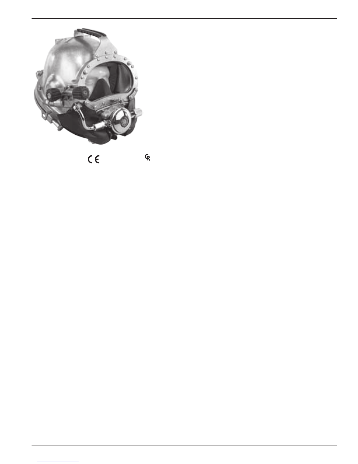
Kirby Morgan® 37 & 57 Helmets
Operations and Maintenance Manual
KMDSI Part # 100-073
The KM37 helmet is covered by U.S. Patent #6,644, 307B2. Foreign and other patents pending.
™
Kirby Morgan Dive Systems, Inc.
1430 Jason Way
Santa Maria, CA 93455, USA
Telephone (805) 928-7772, FAX (805) 928-0342
E-Mail: KMDSI@KirbyMorgan.com, Web Site: www.KirbyMorgan.com
Manual prepared by KMDSI, Dive Lab, Inc. and Marine Marketing and Consulting.
NOTE: This manual is the most current for the Kirby Morgan 37 and 57 Helmet. It is page dated January 2013. Future changes will be shown on page IV and the changed pages will carry the date of change. Previous manuals may
not reect these updates.
Diving with compressed breathing gas is a hazardous activity. Even if you do everything
right there is always the danger that you may be killed or injured. No piece of diving
equipment can prevent the possibility that you may be killed or injured any time you
enter the water.
The Kirby Morgan 37 helmet is CE Approved and meets or exceeds all performance and testing requirements of all government and non-government testing agencies throughout the world. It is approved for
use on all commercial and military work underwater.
Kirby Morgan, SuperLite®, BandMask, Band Mask, KMB, KMB-Band Mask, DSI, Diving Systems International, EXO, REX®,
SuperFlow® and DECA are all registered trademarks of Kirby Morgan Dive Systems, Inc. Use of these terms to describe products
that are not manufactured by KMDSI is illegal.
The two dimensional images (such as photographs and illustrations) of our products are © copyrighted and trademarks of Kirby
Morgan Dive Systems, Inc. The three dimensional forms of our products are trademark, trade design and trade dress protected.
© ⅯⅯⅩⅡ Kirby Morgan Dive Systems, Inc. All rights reserved. This manual is made available for the express use of the owner of
this Kirby Morgan product. No part of this manual may be reproduced, stored in any retrieval system, or transmitted, or used in any
form or by any means, whether graphic, electronic, mechanical, photocopy, or otherwise by technology known or unknown, without
the prior written permission of Kirby Morgan Dive Systems, Inc.
Document Number 130108002

Kirby Morgan® 37 & 57
Warranty Information
KMDSI warrants every new Mask, Helmet, Scuba Regulator, Manifold Block or Kirby Morgan Air Control
System 5 (KMACS 5) (each, a Product) to be free from defects in workmanship for a period of three hun-
dred sixty ve (365) days from the date of purchase from a KMDSI authorized dealer. This warranty covers
all metal and plastic parts, but does NOT cover rubber parts, communications components, or head and chin
cushions. In addition, due to the electrolytic nature of underwater cutting and welding, chrome plating cannot be warranted when the diver engages in these activities.
Any defect of the product in workmanship or material covered by this warranty discovered within three
hundred sixty ve (365) days from the date of purchase must be promptly communicated in writing to the
nearest authorized KMDSI dealer or (if no such dealer in the buyer’s country) contact KMDSI directly
at (805) 928-7772. No Product returns will be accepted by KMDSI without a returned merchandise
authorization (RMA) number from KMDSI. Upon receipt of the RMA from KMDSI, the buyer should
return the defective Product or part, freight prepaid, to an authorized KMDSI dealer or the KMDSI plant, as
directed by the RMA. KMDSI will repair or replace the Product at no charge, within a reasonable time, as it
deems necessary.
This warranty becomes null and void if:
1) The Product is not registered with KMDSI within ten (10) days of purchase, or
2) The Product has not been properly serviced and/or maintained according to KMDSI factory recommended procedures described in the manual or Product updates have not been performed as
recommended by KMDSI, or
3) Unauthorized attachments or modications have been made to the Product, or
4) The Product has been used for purposes other than those for which it was designed, or otherwise
has been abused, misused, or subjected to unusual conditions, or the Product’s intended service has
been exceeded.
EXCEPT AS SPECIFICALLY PROVIDED HEREIN, THERE ARE NO OTHER WARRANTIES,
EXPRESS OR IMPLIED, INCLUDING, BUT NOT LIMITED TO, ANY IMPLIED WARRANTIES
FOR MERCHANTABILITY OR FITNESS FOR A PARTICULAR PURPOSE. THE PRODUCT
COVERED BY THIS WARRANTY IS MARKETED AND SOLD BY KMDSI SOLELY FOR COMMERCIAL OR INDUSTRIAL USE AND IS NOT A CONSUMER PRODUCT INTENDED FOR
PERSONAL, FAMILY, OR HOUSEHOLD USE.
In purchasing any Product subject to this warranty, the buyer agrees that its sole and exclusive remedy and
KMDSI’s entire obligation in contract, tort, or otherwise under this contract will be repair or replacement at
KMDSI’s option of the Product or any parts which KMDSI determines during the applicable warranty period are defective in workmanship or material covered by this warranty. All exchanged parts are the property
of KMDSI. The buyer’s exclusive remedy and the KMDSI’s entire liability in contract, tort, or otherwise is
the payment by KMDSI of the buyer’s actual damages up to but not to exceed the amount paid by the buyer
for the Product.
In no event shall KMDSI be liable to the buyer for indirect, special, incidental or consequential damages (in-
cluding, but not limited to, damages for lost prots, lost sales, loss of business opportunity, or for injury to
persons or property arising out of the use of the Product). Any claim or action for breach of warranty must
II © ⅯⅯⅩⅢ Kirby Morgan Dive Systems, Inc. All rights reserved. Document #130108002

Kirby Morgan® 37 & 57
be commenced within one year following delivery of the Product to the buyer.
Buyer acknowledges that this warranty is the sole and exclusive warranty of the Product and that it supersedes any and all oral or written representations and undertakings between KMDSI, its dealers, and the
buyer relating to the Products. This warranty allocates the risks of product failure between KMDSI and the
buyer, which allocation is recognized by both parties and is reected in the price of the goods. The buyer
acknowledges that it has read this agreement, understands it, and is bound by its terms.
© ⅯⅯⅩⅢ Kirby Morgan Dive Systems, Inc. All rights reserved. Document #130108002 III

Kirby Morgan® 37 & 57
Record Of Changes
It is the responsibility of the owner of this product to register their ownership with Kirby Morgan Dive
Systems, Inc., by sending the warranty card provided. This card is to establish registration for any necessary
warranty work and as a means of communication that allows KMDSI to contact the user regarding this product.
The user must notify KMDSI of any change of address by the user or sale of the product.
All changes or revisions to this manual must be recorded in this document to ensure that the manual is
up to date. Quantities marked in parenthesis.
Change Number Date Description of Change
1 05/16/2008 Reworded: 2.1 Product Specications, 2.2.1 SuperFlow
Demand Regulators, 2.2.2 SuperFlow® 450 Performance Certication and 2.5
Operational Specications & limitations.
Reworded Warnings: Page 23 (2) and page 32.
Temperature limitations on page 24 changed from 36º F to 33º F.
Changed regulator adjustment knob to Flex Knob on page 102. Location number
in second NOTE on page 102 changed to reect correct location
Added: Appendix 3 and 4.
2 08/19/2008 Page III Removed page number column.
Page 17: Updated CE approved graphic on SL-17A/B
Page 18: Added CE approved graphic to KM-47 helmet. Updated CE approved
graphic on SL-27.
Page 20: Updated CE approved graphic on EXO-BR.
Pages 57-58: Moved chapter 5 into two columns.
Page 87: Added gasket warning on page 90 left column.
Page 158-159: Changed torque specications. Overset text arranged on next page
(159).
3 11/05/2008 Added D-Ring to Image on pages 17, 28, and 29.
Blowapart Image Updated with D-Ring on page 32, 38, 129, and 134.
Text Updated on pages 57-58, 131.
Rearranged pages 146-148, added diagram of earphone wire.
Appendix A1: Torque Specications updated on page 158.
4 02/25/2009 Text Updated on pages 144-145.
5 03/11/2009 Page 69, step 7; page 132 step 7; page 133 step 11; page 136 step 3; page 151
step 10: Changed kg cm to Newton Meters.
Page 71: Lacquer thinner changed to acetone.
Page 72: Corrected 35 inch pounds to 20 inch pounds in step 4. Lacquer thinner
changed to acetone.
Page 90: Corrected 75 inch pounds to 100 inch pounds in step 19.
Page 102: Section 7.12.2 “SuperFlow
®
450 Demand Regulator Test for Correct
Adjustment, Fully Assembled,” renumbered to aforementioned section number
from incorrect 7.12.1.
Page 117: Corrected 75 inch pounds to 100 inch pounds in step 8.
Page 121: Corrected 35 inch pounds to 20 inch pounds in step 3.
Page 123: Lacquer thinner changed to acetone.
Page 124: Corrected 35 inch pounds to 20 inch pounds in step 4. Lacquer thinner
changed to acetone.
Page 158: Added Location # 104a 530-020 Screw, exhaust ange.
Page 159: Added location # 176 550-533 Bent tube adapter, 450 Regulator.
®
and SuperFlow® 350
IV © ⅯⅯⅩⅢ Kirby Morgan Dive Systems, Inc. All rights reserved. Document #130108002
Kirby Morgan® 37 & 57
WARNING
6 07/27/2009 Added sections 2.1, 2.2, 2.2.1 and 2.2.2 for CE certication.
7 09/09/2009 Page 64 Section 6.4 step 5 text updated.
8 11/06/2009 Chapter 2: addition of CE conforming criteria.
2.3 Product Specications corrected weight to 32.6 lbs from 30.6 lbs.
9 03/17/2010 Updated images and diagrams with new whiskers
10 02/18/2011 Updated chapter 1.
11 03/23/2011 Updated earphones throughout manual
12 06/08/2011 Changed 61 meters to 67 meters in Appendix 3 Table 4 SuperFlow® / SuperFlow®
350 Regulator High Pressure Regulated Source and Appendix 3 Table 5 Supply
Pressure Guidelines SuperFlow® 450 Stainless Steel Balanced Regulators High
Pressure Regulated Source Supply Pressure Guidelines
13 10/17/2011 Updated CE notifying body number from 0496 to 2049
14 05/09/2012 Updated CE notifying body address
15 06/13/2012 Update copyright date to roman numerals
16 08/29/2012 Updated torque specs for updated BlowAparts
17 01/08/2013 Updated torque spec locations and copyright
Diving with compressed breathing gas is a hazardous activity. Even if you do everything
right there is always the potential for serious injury or death. No one piece of diving
equipment can prevent the possibility that you may be injured or killed any time you
enter the water. We do not herein make any effort to teach the principles of diving. The
information in this manual is intended for users of Kirby Morgan helmets and persons
that maintain or service Kirby Morgan helmets.
© ⅯⅯⅩⅢ Kirby Morgan Dive Systems, Inc. All rights reserved. Document #130108002 V

Kirby Morgan® 37 & 57
Table Of Contents
Warranty Information �������������������������������������������������������������������������������� II
Record Of Changes
Denition of Signal Words Used in this Manual
Chapter 1 General Information KMDSI Products ����������������������������������� 1
1.1 Introduction
1.2 Full-Face Masks and Manifolds
1.3 Kirby Morgan Diving Helmets
Chapter 2 Description & Operational Specications Kirby Morgan 37 &
57 �������������������������������������������������������������������������������������������������������� 9
2.1 CR Marking
2.2 CE Certication
2�2�1 CE Marking ���������������������������������������������������������������������������������� 9
2�2�2 Notied Body ������������������������������������������������������������������������������� 10
2.3 Product Specications
2.4 Regulator Performance
2�4�1 SuperFlow® and SuperFlow® 350 Demand Regulators �������������������������������������� 10
2�4�2 SuperFlow® 450 Performance �������������������������������������������������������������� 10
2.5 Cage Code �������������������������������������������������������������������������������������� 10
2.6 Operational Specications & Limitations ���������������������������������������������������� 10
2.7 Helmet Features
2.8 General Description
2�8�1 Helmet Shell �������������������������������������������������������������������������������� 14
2�8�2 Gas Flow Systems �������������������������������������������������������������������������� 14
2�8�3 Emergency Gas Supply System (EGS) ������������������������������������������������������ 18
2�8�4 Helmet Attachment to the Diver ������������������������������������������������������������� 19
2�8�5 Sealing Arrangement ����������������������������������������������������������������������� 20
2�8�6 Reducing Carbon Dioxide ������������������������������������������������������������������ 20
2�8�7 Communications ���������������������������������������������������������������������������� 20
2�8�8 Equalizing the Middle Ear ������������������������������������������������������������������� 20
2�8�9 Face Port or Viewing Lens ������������������������������������������������������������������ 21
2.9 Accessories
2�9�1 Eye Protection for Welding ������������������������������������������������������������������ 21
2�9�2 Hot Water Shroud for SuperFlow® 350 ������������������������������������������������������ 21
2�9�3 Special Regulator Tools for SuperFlow® 350 ������������������������������������������������ 22
2.10 Helmet Transport And Storage
2�10�1 Helmet Carrying Bag ���������������������������������������������������������������������� 23
2.11 Use of Kirby Morgan Original Replacement Parts ����������������������������������������� 24
Chapter 3 Operating Instructions �������������������������������������������������������� 25
3.1 Introduction
3.2 Design Purpose
3.3 First Use of Your Kirby Morgan Diving Helmet ���������������������������������������������� 26
3.4 Initial Adjustments to Your Helmet
3�4�1 Head Cushion ������������������������������������������������������������������������������ 27
3.4.1.1 Head Cushion Removal ������������������������������������������������������������������� 27
3.4.1.2 Clean and Inspect ������������������������������������������������������������������������ 27
3.4.1.3 Stufng ����������������������������������������������������������������������������������27
�������������������������������������������������������������������������������� IV
������������������������������������������������ XIII
�������������������������������������������������������������������������������������� 1
���������������������������������������������������������������� 2
������������������������������������������������������������������ 4
�������������������������������������������������������������������������������������� 9
���������������������������������������������������������������������������������� 9
������������������������������������������������������������������������� 10
������������������������������������������������������������������������ 10
�������������������������������������������������������������������������������� 11
���������������������������������������������������������������������������� 14
������������������������������������������������������������������������������������� 21
�������������������������������������������������������������� 22
������������������������������������������������������������������������������������� 25
��������������������������������������������������������������������������������� 25
������������������������������������������������������������ 26
VI © ⅯⅯⅩⅢ Kirby Morgan Dive Systems, Inc. All rights reserved. Document #130108002

Kirby Morgan® 37 & 57
3.4.1.4 Head Cushion Adjustment ����������������������������������������������������������������� 27
3.4.1.5 Foam Trimming tips ����������������������������������������������������������������������� 27
3.4.1.6 Foam Stufng Tips ������������������������������������������������������������������������ 28
3.4.1.7 Adding Earphone Holes to the Head Cushion ������������������������������������������������ 28
3�4�2 Head Cushion Foam Spacer (HCFS) �������������������������������������������������������� 28
3.4.2.1 Installation of Head Cushion Foam Spacer (HCFS) �������������������������������������������� 28
3.4.2.2 Donning the Head Cushion Foam Spacer (HCFS) ��������������������������������������������� 31
3.4.2.3 Maintenance of the Head Cushion Foam Spacer (HCFS) �������������������������������������� 32
3.4.2.3 Stufng the Head Cushion Foam Spacer (HCFS) ���������������������������������������������32
3�4�2 Trimming the Neck Dam �������������������������������������������������������������������� 32
3�4�3 Adjusting the Neck Pad ��������������������������������������������������������������������� 33
3.5 Pre Dress-In Procedure
������������������������������������������������������������������������ 34
3�5�1 Pre-Dive Visual Inspection ������������������������������������������������������������������34
3.6 Preparing the Helmet for Diving
��������������������������������������������������������������� 34
3�6�1 Clean Face Port ���������������������������������������������������������������������������� 34
3�6�2 Check Moving Parts ������������������������������������������������������������������������ 34
3�6�3 Check Communications �������������������������������������������������������������������� 36
3�6�4 One Way Valve Check ���������������������������������������������������������������������� 36
3.7 Emergency Gas System (EGS)
���������������������������������������������������������������� 36
3.8 Setting Up to Dive ������������������������������������������������������������������������������ 39
3�8�1 Flushing Out the Umbilical ������������������������������������������������������������������ 39
3�8�2 Connecting the Umbilical to the HelmetWhen you connect the hose to the helmet be sure
to use a wrench to hold the adapter, or inlet tting, and a second wrench to turn the swivel tting
on the hose� If this is not done, the adapter will turn inside the one way valve� If this happens
repeatedly the threads will wear and the valve will need to be replaced�
�������������������������� 40
3�8�3 Opening the Breathing Gas Supply to the Helmet�������������������������������������������40
3�8�4 Fogging Prevention �������������������������������������������������������������������������41
3�8�5 Donning The KM 37 or 57 ������������������������������������������������������������������� 41
3�8�6 Testing the Breathing System ���������������������������������������������������������������43
3�8�7 Adjust Regulator for Low Work Rates �������������������������������������������������������43
3�8�8 Sealing Integrity Check ��������������������������������������������������������������������� 43
3.9 Removing the Helmet �������������������������������������������������������������������������� 44
3.10 Diving Procedures
3�10�1 Standing By to Dive ����������������������������������������������������������������������� 44
3�10�2 Attaching the Umbilical to the HarnessThe umbilical must now be hooked to the diver’s
harness by means of a suitable clip that is bound to the umbilical� Some divers and companies
prefer a quick release clip and others prefer a clip that is screwed together so the diver cannot
easily remove it from their harness� The securing of the umbilical keeps the pull of the hose at the
diver’s harness and not on the helmet�
3�10�3 Diver Dons Helmet ������������������������������������������������������������������������ 45
3�10�4 Diver Check Gas Flow Systems ����������������������������������������������������������� 45
3�10�5 Communications Check ������������������������������������������������������������������� 45
3�10�6 Diver Ready ������������������������������������������������������������������������������� 45
3�10�7 Water Entry and Descent ������������������������������������������������������������������45
3.11 Emergency Procedures
3�11�1 Flooding ����������������������������������������������������������������������������������� 45
3�11�2 Inhalation Resistance ���������������������������������������������������������������������� 46
3�11�3 Gas Flow Stops ��������������������������������������������������������������������������� 46
3�11�4 Demand Regulator Free Flow ��������������������������������������������������������������46
3.12 Post Dive Procedures
���������������������������������������������������������������������������� 44
����������������������������������������������������������� 44
���������������������������������������������������������������������� 45
������������������������������������������������������������������������ 46
© ⅯⅯⅩⅢ Kirby Morgan Dive Systems, Inc. All rights reserved. Document #130108002 VII

Kirby Morgan® 37 & 57
3�12�1 Removing the Equipment ������������������������������������������������������������������ 46
3�12�2 Removing the Helmet ��������������������������������������������������������������������� 46
3�12�3 Storage of the Helmet Between Dives ����������������������������������������������������� 46
Chapter 4 Troubleshooting ������������������������������������������������������������������ 49
4.1 General ������������������������������������������������������������������������������������������ 49
4.2 Communication Malfunction
4.3 One Way Valve Malfunction
4.4 Side Valve Malfunction
������������������������������������������������������������������������� 50
4.5 Water Leakage Into Helmet
������������������������������������������������������������������ 49
������������������������������������������������������������������� 49
������������������������������������������������������������������� 50
4.6 Demand Regulator Malfunction ��������������������������������������������������������������� 51
4.7 Emergency Gas Supply Valve
����������������������������������������������������������������� 51
Chapter 5 Inspection and Maintenance ����������������������������������������������� 53
5.1 Routine Maintenance
5�1�1 Daily Pre-Dive Maintenance A2�3 �����������������������������������������������������������53
5�1�2 Daily Post Dive Maintenance A2�6 ���������������������������������������������������������� 53
5�1�3 Supervisors Equipment Checks A2�4 and A2�5 ��������������������������������������������� 53
5.2 Monthly Maintenance
5.3 Yearly Maintenance ���������������������������������������������������������������������������� 53
5�3�1 Overhaul/Inspection Checklist A2�1 ��������������������������������������������������������� 53
�������������������������������������������������������������������������� 53
�������������������������������������������������������������������������� 53
Chapter 6 General Preventative Maintenance �������������������������������������55
6.1 Introduction
6.2 Required tools, Cleaning Agents, Lubrication �����������������������������������������������55
6�2�1 Component and Parts Cleaning ������������������������������������������������������������� 56
6�2�2 Component and Parts Lubrication ���������������������������������������������������������� 56
6�2�3 Teon® Tape �������������������������������������������������������������������������������� 57
6�2�4 RTV Sealant ��������������������������������������������������������������������������������57
6�2�5 Thread Locker ������������������������������������������������������������������������������57
6.3 General Cleaning & Inspection Procedures
6�3�1 O-Ring Removal/Inspection/Cleaning and Lubrication �������������������������������������� 58
6.3.1.1 O-Ring Removal: ������������������������������������������������������������������������ 58
6.3.1.2 O-Ring Inspection: ������������������������������������������������������������������������ 58
6.3.1.3 O-Ring Reuse: ���������������������������������������������������������������������������� 58
6�3�2 General Cleaning Guidelines ��������������������������������������������������������������� 58
6.3.2.1 Mild Soap Solution for General Cleaning and Leak Detector Use ������������������������������� 59
6.3.2.2 Acidic Cleaning Solution and Procedures ����������������������������������������������������59
6.3.2.3 Germicidal Cleaning Solutions and Procedure ������������������������������������������������59
6.4 Daily Maintenance
6.5 Monthly Maintenance (or between jobs) ����������������������������������������������������� 61
6�5�1 Locking Collar Assembly & Helmet Ring ��������������������������������������������������� 61
6�5�2 Neck Dam Ring Assembly ������������������������������������������������������������������ 61
6�5�3 Head Cushion and Chin Cushion ����������������������������������������������������������� 62
6�5�4 Communications Inspection ����������������������������������������������������������������62
6�5�5 Lubricate Nose Block O-Rings �������������������������������������������������������������� 62
6.6 Inspect the Exhaust Valve
6�6�1 For Helmets Equipped with the Tri-Valve™ �������������������������������������������������62
6�6�2 For Helmets Equipped with the Quad Valve™ Exhaust �������������������������������������63
������������������������������������������������������������������������������������� 55
�������������������������������������������������� 57
������������������������������������������������������������������������������ 60
��������������������������������������������������������������������� 62
Chapter 7.0 Breathing System Maintenance and Repairs ��������������������65
7.1 Introduction
7.2 One Way Valve
������������������������������������������������������������������������������������� 65
���������������������������������������������������������������������������������� 65
VIII © ⅯⅯⅩⅢ Kirby Morgan Dive Systems, Inc. All rights reserved. Document #130108002

Kirby Morgan® 37 & 57
7�2�1 Disassembly Of The One Way Valve �������������������������������������������������������� 65
7�2�2 Reassembly of the One Way Valve ���������������������������������������������������������� 66
7.3 Side Block Assembly
��������������������������������������������������������������������������� 67
7�3�1 General ������������������������������������������������������������������������������������� 67
7�3�2 Side Block Assembly Removal �������������������������������������������������������������� 67
7�3�3 Separating the Side Block Assembly from the Helmet Shell ��������������������������������67
7�3�4 Side Block Assembly Replacement ��������������������������������������������������������� 68
7.4 Defogger Valve
��������������������������������������������������������������������������������� 70
7�4�1 Disassembly of the Defogger Valve ���������������������������������������������������������70
7�4�2 Cleaning and Lubricating ������������������������������������������������������������������� 71
7�4�3 Reassembly of the Defogger Valve ����������������������������������������������������������71
7.5 Emergency Valve Assembly
������������������������������������������������������������������� 72
7�5�1 Disassembly of the Emergency Valve ������������������������������������������������������� 72
7�5�2 Cleaning and Lubricating ������������������������������������������������������������������� 73
7�5�3 Reassembly of Emergency Valve ����������������������������������������������������������� 74
7�5�4 Leak Testing the EGS Valve �����������������������������������������������������������������75
7.6 Bent Tube Assembly
��������������������������������������������������������������������������� 75
7�6�1 General ������������������������������������������������������������������������������������� 75
7�6�2 Removal of the Bent Tube Assembly �������������������������������������������������������� 76
7�6�3 Inspection of Bent Tube Assembly ���������������������������������������������������������� 76
7�6�4 Installation of the Bent Tube Assembly������������������������������������������������������ 76
7.7 SuperFlow® 350 Demand Regulator ���������������������������������������������������������� 77
7�7�1 General Regulator Information �������������������������������������������������������������� 77
7�7�2 SuperFlow® 350 Demand Regulator Test for Correct Adjustment, Fully Assembled ���������77
7�7�3 Inspection of SuperFlow® 350 Regulator Body Interior ������������������������������������� 78
7�7�4 SuperFlow® 350 Demand Regulator Bias Adjustment Servicing, Demand Regulator on the
Helmet
�������������������������������������������������������������������������������������������� 78
7�7�5 Reassembly of the SuperFlow® 350 Regulator Adjustment System ������������������������� 79
7�7�6 SuperFlow® 350 Demand Regulator Removal from Helmet ���������������������������������80
7�7�7 Disassembly of the SuperFlow® 350 Demand Regulator ������������������������������������ 81
7�7�8 Inspection of SuperFlow® 350 Demand Regulator Parts ������������������������������������ 82
7�7�9 Reassembly of the SuperFlow® 350 Demand Regulator ������������������������������������ 84
7�7�10 Tuning the SuperFlow® 350 Regulator ����������������������������������������������������� 88
7�7�11 SuperFlow® 350 Regulator Steady Flows When Pressured Up: Special Tools Used ������� 90
7.8 Oral Nasal ��������������������������������������������������������������������������������������� 92
7�8�1 Oral Nasal General Information ������������������������������������������������������������� 92
7�8�2 Oral Nasal Removal ������������������������������������������������������������������������ 92
7�8�3 Inspection of Oral Nasal �������������������������������������������������������������������� 92
7�8�4 Oral Nasal Replacement �������������������������������������������������������������������� 93
7.9 Quad Valve
7�9�1 Quad Valve™ Assembly Removal ������������������������������������������������������������ 94
7�9�2 Quad Valve™ Exhaust Valves ����������������������������������������������������������������95
7.9.2.1 Quad Valve™ Exhaust Valve Replacement ����������������������������������������������������95
7.9.2.2 SuperFlow® 350 Regulator Exhaust Valve Replacement ���������������������������������������96
7�9�3 Quad Valve™ Assembly Installation ��������������������������������������������������������� 96
7.10 Water Dump Exhaust Body
7�10�1 Water Dump Valve Removal ��������������������������������������������������������������� 97
7�10�2 Water Dump Valve Replacement ���������������������������������������������������������� 97
7�10�3 Water Dump Valve Body Removal ��������������������������������������������������������� 97
7�10�4 Water Dump Valve Body Remounting ����������������������������������������������������� 97
™
Exhaust Assembly �������������������������������������������������������������� 94
������������������������������������������������������������������ 97
© ⅯⅯⅩⅢ Kirby Morgan Dive Systems, Inc. All rights reserved. Document #130108002 IX

Kirby Morgan® 37 & 57
7.11 Reinstalling the Quad Valve™ Exhaust Assembly ������������������������������������������ 98
7�12 SuperFlow® 450 Stainless Balanced Regulator ���������������������������������������������� 99
7�12�1 General ������������������������������������������������������������������������������������ 99
7�12�2 SuperFlow® 450 Demand Regulator Test for Correct Adjustment, Fully Assembled �������� 99
7�12�3 Adjusting the SuperFlow® 450 ����������������������������������������������������������� 100
7�12�4 SuperFlow® 450 Demand Regulator Bias Adjustment Field Service with Demand Regulator
on Helmet
���������������������������������������������������������������������������������������101
7�12�5 SuperFlow® 450 Regulator Removal ����������������������������������������������������� 106
7�12�6 SuperFlow® 450 Disassembly ����������������������������������������������������������� 107
7�12�7 Assembly of the SuperFlow® 450 Regulator ��������������������������������������������� 109
7.12.7.1 Assembly of the Flex Knob�������������������������������������������������������������� 109
7.12.7.2 Assembly of SuperFlow® 450 Regulator ���������������������������������������������������110
7�12�8 SuperFlow® 450 Regulator Installation ����������������������������������������������������114
Chapter 8 Corrective Maintenance �����������������������������������������������������117
8.1 General �����������������������������������������������������������������������������������������117
8.2 Helmet Shell Inspection�����������������������������������������������������������������������117
8.3 Nose Block Assembly
8�3�1 Nose Block Assembly Removal ������������������������������������������������������������118
8�3�2 Nose Block Device Replacement ����������������������������������������������������������119
8.4 Handle and Weights �������������������������������������������������������������������������� 120
8�4�1 Handle Removal ������������������������������������������������������������������������� 120
8�4�2 Handle Replacement ��������������������������������������������������������������������� 120
8�4�3 Side Weight Removal ��������������������������������������������������������������������� 120
8�4�4 Port Weight Replacement ����������������������������������������������������������������� 122
8�4�5 Top Weight �������������������������������������������������������������������������������� 123
8.4.5.1 Top Weight Removal �������������������������������������������������������������������� 123
8.4.5.2 Top Weight Replacement ���������������������������������������������������������������� 123
8.5 Face Port �������������������������������������������������������������������������������������� 124
8�5�1 General ����������������������������������������������������������������������������������� 124
8�5�2 Face Port and Nose Block Device Removal ����������������������������������������������� 124
8�5�3 Face Port and Nose Block Replacement �������������������������������������������������� 126
8�5�4 Special Note Regarding Ports ������������������������������������������������������������ 127
8.6 Neck Ring Assembly ������������������������������������������������������������������������ 128
8�6�1 General Information on Neck Dams ������������������������������������������������������� 128
8�6�2 Removal of the Neck Dam ���������������������������������������������������������������� 128
8�6�3 Neoprene Neck Dam Replacement ������������������������������������������������������� 128
8�6�4 Latex Neck Dam Replacement ������������������������������������������������������������ 131
8�6�5 Trimming a Latex Neck Seal �������������������������������������������������������������� 132
8.7 Pull Strap �������������������������������������������������������������������������������������� 133
8�7�1 Pull Strap Removal ����������������������������������������������������������������������� 133
8�7�2 Pull Strap Replacement ������������������������������������������������������������������� 133
8.8 Chin Strap
������������������������������������������������������������������������������������� 133
8�8�1 Chin Strap Removal ���������������������������������������������������������������������� 133
8�8�2 Chin Strap Replacement ������������������������������������������������������������������ 133
8.9 O-Ring Seal Replacement ������������������������������������������������������������������ 134
8.10 Helmet Ring ��������������������������������������������������������������������������������� 135
8�10�1 Helmet Ring Repairs ��������������������������������������������������������������������� 135
8.11 Sealed Pull Pins
8�11�1 Removal of Sealed Pull Pins ������������������������������������������������������������� 135
8�11�2 Replacement of Sealed Pull Pins �������������������������������������������������������� 135
�������������������������������������������������������������������������118
����������������������������������������������������������������������������� 135
X © ⅯⅯⅩⅢ Kirby Morgan Dive Systems, Inc. All rights reserved. Document #130108002

Kirby Morgan® 37 & 57
8.12 Swing Tongue Catch
8�12�1 Disassembly of the Swing Tongue Catch ������������������������������������������������ 136
8�12�2 Reassembly of the Swing Tongue Catch ������������������������������������������������� 136
����������������������������������������������������������������������� 136
8.13 Locking Collar/Neck Pad ������������������������������������������������������������������� 138
8�13�1 Locking Collar Removal ����������������������������������������������������������������� 138
8�13�2 Locking Collar Disassembly ������������������������������������������������������������� 139
8�13�3 Locking Collar Reassembly �������������������������������������������������������������� 140
8.15 Head Cushion (pre October 2012) ��������������������������������������������������������� 142
8�15�1 Head Cushion Foam ��������������������������������������������������������������������� 142
8.16 Chin Cushion Foam
8.15 Communications System
8�15�1 General ���������������������������������������������������������������������������������� 143
8�15�2 Earphone Inspection �������������������������������������������������������������������� 143
8�15�3 Removal of Communications Assembly ������������������������������������������������� 144
8�15�4 Replacement of Communications Assembly ��������������������������������������������� 144
8�15�5 Microphone Replacement ��������������������������������������������������������������� 145
8�15�6 Earphone And Wire Assembly Replacement ��������������������������������������������� 145
8�15�7 Waterproof Connector ������������������������������������������������������������������� 146
8.15.7.1 Connector Removal �������������������������������������������������������������������� 146
8.15.7.2 Connector Replacement ���������������������������������������������������������������� 147
8�15�8 Terminal Connections in the Waterproof Connector ������������������������������������� 147
8�15�9 Communications Posts ������������������������������������������������������������������ 149
8.15.9.1 Communications Post Removal ��������������������������������������������������������� 149
8.15.9.2 Communications Post Replacement ����������������������������������������������������� 149
������������������������������������������������������������������������� 142
������������������������������������������������������������������� 143
Chapter 9 Accessories for the Kirby Morgan 37 & 57 ������������������������ 151
9.1 Introduction ����������������������������������������������������������������������������������� 151
9.2 Hot Water Shroud for KM37 ����������������������������������������������������������������� 151
9�2�1 Hot Water Shroud Installation Procedures for KM37 �������������������������������������� 151
9.3 Low Pressure Inator Hose ������������������������������������������������������������������ 154
9�3�1 Installation of the Low Pressure Inator Hose ��������������������������������������������� 154
9.4 Weld Lens Assembly ������������������������������������������������������������������������� 155
9�4�1 Weld Lens Assembly Installation ���������������������������������������������������������� 155
9.5 Weld Shield Assembly ����������������������������������������������������������������������� 156
9�5�1 Weld Shield Assembly Installation �������������������������������������������������������� 156
9.6 Use of Quick Disconnect �������������������������������������������������������������������� 156
9.7 Accessory Mounting Brackets �������������������������������������������������������������� 157
9�7�1 Mount Bracket Installation ���������������������������������������������������������������� 157
Table of Equivalents �������������������������������������������������������������������������� 159
Appendix 1: Torque Specications ���������������������������������������������������� 160
Note on Torque Specications ���������������������������������������������������������� 161
Appendix 1: Torque Specications Continued������������������������������������ 161
Appendix A2 Maintenance and Inspection Procedures ���������������������� 162
Appendix 3 Supply Pressure Requirements & Tables ������������������������� 164
Appendix 3 Table 1 Work Rate Expressed as Respiratory Minute Volume (RMV)*
Appendix 3 Table 2 Compressor Supply Table SuperFlow® and SuperFlow® 350 ���������� 165
Appendix 3 Table 3 SuperFlow® 450 SS Balanced Regulator �������������������������������� 166
Appendix 3 Table 2 Compressor Supply Table SuperFlow® and SuperFlow® 350 Continued
����������������������������������������������������������������������������������������������������� 166
Appendix 3 Table 3 SuperFlow
®
450 SS Balanced Regulator Continued ������������������� 167
��������� 165
© ⅯⅯⅩⅢ Kirby Morgan Dive Systems, Inc. All rights reserved. Document #130108002 XI

Kirby Morgan® 37 & 57
Appendix 3 Table 4 SuperFlow® / SuperFlow® 350 RegulatorHigh Pressure Regulated
Source
Appendix 3 Table 3 SuperFlow
��������������������������������������������������������������������������������������������� 168
®
450 SS Balanced Regulator Continued ������������������� 168
Appendix 3 Table 5 Supply Pressure Guidelines SuperFlow® 450 Stainless Steel Balanced
Regulators High Pressure Regulated Source Supply Pressure Guidelines ����������������� 169
Appendix 4 Standard Kirby Morgan Surface Supply Pressure Formula Old Method
��������������������������������������������������������������������������������������� 169
XII © ⅯⅯⅩⅢ Kirby Morgan Dive Systems, Inc. All rights reserved. Document #130108002

Kirby Morgan® 37 & 57
CAUTION
DANGER
WARNING
WARNING
WARNING
WARNING
WARNING
WARNING
Definition of Signal Words Used in this Manual
For your protection, pay particular attention to items identied by signal words in this manual. These terms are identied
as, CAUTION, WARNING AND DANGER. It is especially important for you to read and understand these sections.
This word indicates an imminently hazardous situation, which if not avoided, could result in death or serious injury.
This word indicates a potentially hazardous situation, which, if not avoided, could result
in death or serious injury.
This word indicates a potentially hazardous situation, which if not avoided, may result in
minor or moderate injury. It may also be used to alert against unsafe practices.
If English is not your native language and you have any difficulty understanding the language of
any warnings as they appear in the manual, please have them translated.
Este é um aviso importante. Queira mandá-lo traduzir.
Este es un aviso importante. Sirvase mandario traducir.
Quest è un avviso importante. Tradurlo.
Ceci est important. Veuillez traduire.
Diese Mitteilung ist wichtig. Bitte übersetzen lassen.
If you have any questions concerning this manual or the operation of your helmet, contact KMDSI (805) 928-7772 or
by Email at kmdsi@KirbyMorgan.com or Dive Lab Inc. (850) 235-2715 or at Divelab@aol.com
IMPORTANT: A word about this manual. We have tried to make this manual as comprehensive and factual
as possible. We reserve the right however, to make changes at any time, without notice, in prices, colors, materials,
equipment, specications, models and availability. Since some information may have been updated since the time
of printing, please contact your local KMDSI dealer if you have any questions. Periodically KMDSI Operations and
Maintenance Manuals are reviewed. Any updates/changes will be posted on the KMDSI website and may be downloaded for insertion/correction.
Important Safety Information:
This Kirby Morgan diving helmet is intended for use by trained divers who have successfully completed a recognized
training course in surface supplied diving.
© ⅯⅯⅩⅢ Kirby Morgan Dive Systems, Inc. All rights reserved. Document #130108002 XIII
Kirby Morgan® 37 & 57
DANGER
WARNING
DANGER
DANGER
WARNING
WARNING
Follow all the instructions in this manual carefully and heed all safety precautions. Improper use of this diving helmet could result in serious injury or death.
Kirby Morgan Dive Systems, Inc. (KMDSI) warns all divers who use the Kirby Morgan
diving helmet to be sure to use only KMDSI original parts from a KMDSI authorized dealer. Although other parts, O-rings and fittings may appear to fit on Kirby Morgan diving
helmets, they may not be manufactured to the same standards maintained by KMDSI.
The use of any parts other than KMDSI original parts may lead to equipment failure and
accidents.
Diving in waters that are chemically, biologically, or radiologically contaminated is extremely hazardous. Although Kirby Morgan diving helmets may be adapted for use in
some contaminated environments, special training, equipment, and procedures are
necessary. Do not dive in a contaminated environment unless you have been thoroughly
trained and equipped for this type of diving.
Read this manual before using or maintaining the helmet, even if you have experience with other diving helmets. If
you have purchased the helmet new from a dealer, be sure to send in the warranty registration card so we may
keep you informed of any safety notices that affect this product. If you resell or loan this helmet to another diver,
be sure this manual accompanies the helmet and that the person reads and understands the manual. In addition to the
manual a log book should be used to log all repairs, maintenance and use.
Diving is a life threatening occupation. Even if you do everything right you can still be
killed or injured. None of the models of Kirby Morgan helmets or masks can prevent accidents, injuries or death due to improper training, poor-health, improper supervision,
improper job requirements, improper maintenance or acts of God.
This helmet was completely checked and should be ready to dive as it was shipped from
the factory. However, it is always the diver’s responsibility to check all the components
of the helmet prior to diving.
Any and all fiberglass repairs done to this helmet MUST be done by a KMDSI factory
trained repair facility. Painting is not recommended by KMDSI. Furthermore, many diving
companies will not allow painted helmets to be used because painting can mask previous fiberglass damage. KMDSI certified technicians are not responsible for certifying
helmets free from damage during annual overhauls.
Helmet shells can be re-gel coated by authorized/certified KMDSI trained technicians
that have received fiberglass training by KMDSI. Helmets that are to be painted for cosmetic purposes, should be first, certified free of fiberglass damage by an authorized
KMDSI technician certified in fiberglass repair. A log entry should be made in the helmet log that the helmet was free of damage prior to painting. Keep in mind other KMDSI
technician can refuse to work on helmet shells that have previously been painted or
repaired by non KMDSI certified persons.
This manual is supplied to the original purchaser of this helmet. If you have any questions about the use of the helmet
or you need another copy of this manual, Part Number 100-073, contact KMDSI or your nearest KMDSI dealer or
may be downloaded free from the KMDSI website at www.KirbyMorgan.com.
XIV © ⅯⅯⅩⅢ Kirby Morgan Dive Systems, Inc. All rights reserved. Document #130108002
Kirby Morgan® 37 & 57
DANGER
DANGER
WARNING
DANGER
WARNING
If you have any questions regarding the use, maintenance, or operation of this helmet, contact KMDSI at (805) 928-
7772, fax: (805) 928-0342, or e-mail: kmdsi@KirbyMorgan.com.
Kirby Morgan masks and helmets are cleaned and lubricated for oxygen service when they come from the factory. However, if the helmet is used with an
oil lubricated air compressor, contamination with hydrocarbons may result.
If the breathing system in the helmet is exposed to hdrocarbons, it must be
cleaned for oxygen service and lubricated with oxygen safe lubricants before
using it again with breathing mixtures containing a high percentage of oxygen. If this is not done, fires and explosions may result, exposing the user to
serious personal injury or death.
Components requiring lubrication, should only be lubricated with oxygen compatible lubricants such as Christo-
Lube®, Fluorolube®, or Krytox®. Lubricants must be used sparingly and should not be mixed with other lubricants.
KMDSI helmets and masks are intended for underwater use only and should only be
used by qualified divers that have received proper training in the use of this type of
equipment. KMDSI helmets and masks should not be used or worn without the appropriate life support systems, such as air or gas supplies and support personnel as described in this manual.
KMDSI helmets and masks should never be used for motor sport racing, aviation /
space craft use, or for chemical warfare use. The helmet must never be used by persons
in poor physical condition, by persons with previous head neck or back injuries which
could be aggravated by its use. The helmet should not be used by persons under the influence of drugs or alcohol. Furthermore, infants, children, or persons under the age of
18 should never wear KMDSI helmets and masks. Failure to pay heed to the above could
result in serious injury or death.
Never use the helmet without first completing all pre-dive maintenance and set up pro-
cedures.
Do not use KMDSI masks or helmets in currents exceeding 3.0 knots Use in currents
greater than 3 knots may allow water to enter the exhaust valve, possibly causing regulator flooding.
Surface-supplied diving can be a strenuous activity. Most Kirby Morgan helmets weigh
in excess of 27 pounds. KMDSI recommends that persons with a previous neck or back
injury seek professional medical approval prior to engaging in surface supplied diving
operations using any Kirby Morgan helmet. Use of any Kirby Morgan helmet with a preexisting physical/medical condition may result in death or serious injury.
The information contained in this manual is intended to aid the user in optimizing the performance of this helmet.
The application of some of this information will depend on the diving situation and the use of associated equipment.
Many countries have specic laws and rules regarding commercial diving. It is important for the user to understand
the rules, regulations, and philosophy imposed by the governing, regulating bodies whenever using commercial diving
equipment.
Whenever KMDSI helmets or masks are used in European Countries, which have adopted the C.E. certication programs, they must only be used with C.E. certied components. Diving operations should only be conducted within the
© ⅯⅯⅩⅢ Kirby Morgan Dive Systems, Inc. All rights reserved. Document #130108002 XV

Kirby Morgan® 37 & 57
limits of the operational specications, and in accordance with the rules and regulations established by the governing
authority in the specic country or geographical location where the diving operations are being conducted. If you have
any questions concerning this manual or the operation of your helmet, contact KMDSI (805) 928-7772 or at
kmdsi@KirbyMorgan.com or Dive Lab Inc. (850) 235-2715 or at Divelab@aol.com
XVI © ⅯⅯⅩⅢ Kirby Morgan Dive Systems, Inc. All rights reserved. Document #130108002
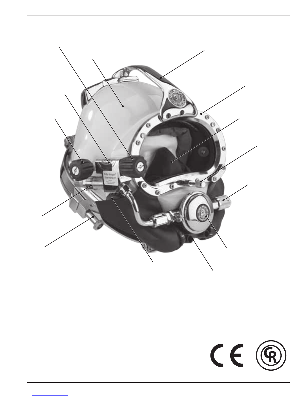
Defog Free Flow
Valve Knob
Helmet Shell
Sideblock
Kirby Morgan® 37 & 57
Handle
Port Retainer
EGS Valve
Non-Return Valve
Pull Pin
Oral Nasal Mask
Equalization Device
Regulator Adjustment
Knob
Purge Button
The Kirby Morgan 37 helmet
© ⅯⅯⅩⅢ Kirby Morgan Dive Systems, Inc. All rights reserved. Document #130108002 XVII
Communications Port
Quad Valve™ Exhaust
(standard on all Kirby Morgan 37
helmets from 2005 on)
A
R
T
Y
E
L
D
L
A
I
-
C
R
E
M
M
O
C
D
E
T
S
E
T
B
A
P
R
O
F
E
S
S
I
O
N
A
L
D
I
V
I
N
G
L
E
G
V
E
I
A
D
R
-
™


Kirby Morgan® 37 & 57
STOP!
BEFORE GOING FURTHER-
This manual will refer to location numbers in specic drawings, or in the exploded view, which is
in the back of this manual. These numbers are called “location” numbers. They are used to nd
the referred to parts in the drawings in this manual only. They are not the part number. Next to
the exploded drawing is a list of the “location” numbers that match the Kirby Morgan part numbers along with the name of the part. Always check the part number when ordering to make sure
it is correct. When ordering, always specify the helmet model number and serial number as well.
Chapter 1
General Information KMDSI Products
1.1 Introduction
The Kirby Morgan Corporation was started in 1965.
The copper and brass “Heavy Gear” or “Standard
Dress” helmets wer e the rst hel mets manufactu red by
the company. Over the years Kirby Morgan designed,
manufactured and sold many different helmets and
masks for commercial divers.
Staying active in commercia l d iving has contributed to
the successful design innovations of KMDSI products.
This may be the primary reason for the acceptance of
our designs by professional divers.
Bev Morgan has designed more than fty-seven diving hel mets a nd over 40 diving masks. All employees
of KMDSI participate as part of the Kirby Morgan
design team. It would not be possible for us to supply
the commercial, military, scientic, and public service
diving industries with our equipment, wit hout the team
of people that make up Kirby Morgan Dive Systems,
Inc. (KMDSI)
We feel it is important for the reader to understand
that we at KMDSI consider ourselves as only part
of the process along the path in diving equipment
design. We welcome all input from our customers.
The thinking of many good divers, diving equipment
engineers, d iving medical specia lists, diving organ ization administrators and their supporting personnel has
contributed to the current state of the art of diving.
Each piece of gear we manufacture has in it some of
the thinking of those who have gone before us. To
all those people who gave something of themselves
to the men and women who work underwater, we
express a thank you.
We have a strong commitment to providing the best
diving equipment and service possible. This thinking
has been the policy of Kirby Morgan Dive Systems,
Bev Morgan, Chairman of the Board
Kirby Morgan Dive Systems, Inc.
Inc. and we will continue to take this approach to
our work.
Our extensive dealer network makes it easy to obtain
genuine Kirby Morgan replacement parts, as well as
technical assistance worldwide.
KMDSI has always concentrated on designing and
manufacturing diving equipment that allows most
repairs, inspections, and all routine maintenance to
be performed by the user. Most routine preventative
and corrective maintenance can be accomplished by
the user utilizing this manual, the KMDSI Tool Kit
(P/N 525-620) and common hand tools. Technician
training is available through Dive Lab Inc. Information can be obtained on line at www.divelab.com or
by telephone at 850-235-2715.
© ⅯⅯⅩⅢ Kirby Morgan Dive Systems, Inc. All rights reserved. Document #130108002 1
Kirby Morgan® 37 & 57
C
O
M
M
E
R
C
I
A
L
L
Y
R
A
T
E
D
-
P
R
O
F
E
S
S
I
O
N
A
L
D
I
V
I
N
G
G
E
A
R
-
D
I
V
E
L
A
B
T
E
S
T
E
D
™
C
O
M
M
E
R
C
I
A
L
L
Y
R
A
T
E
D
-
P
R
O
F
E
S
S
I
O
N
A
L
D
I
V
I
N
G
G
E
A
R
-
D
I
V
E
L
A
B
T
E
S
T
E
D
™
1.2 Full-Face Masks and Manifolds
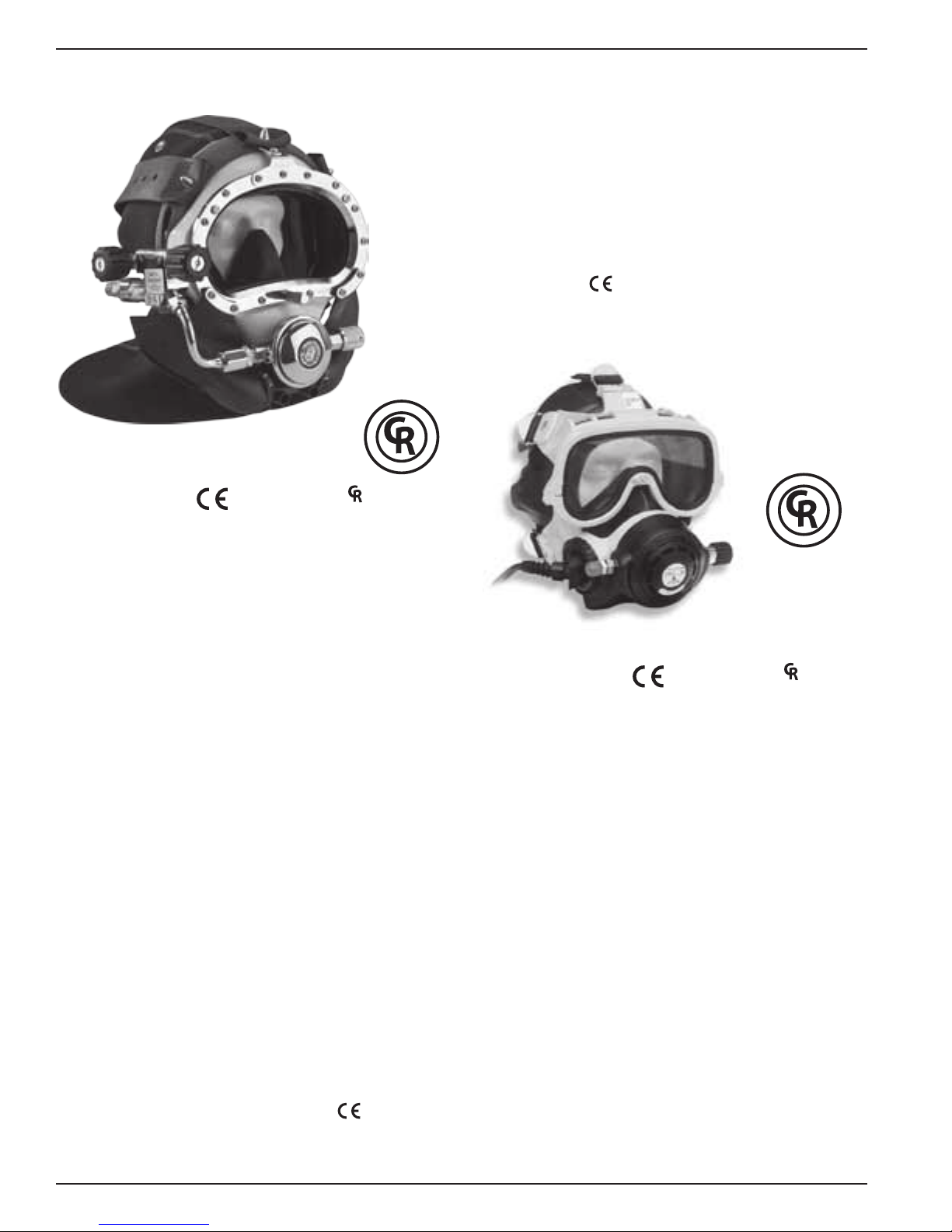
KMB® 18 A/B
approved and ™ marked
The EXO Full Face Mask is designed for both
surface supplied and scuba diving. By enclosing the
divers eyes, nose and mouth, the EXO permits nearly
normal speech when used in conjunction with most
wireless, and all hard wire underwater communication systems.
The EXO BR (BALANCED REGULATOR) shown
here is designed to meet or exceed recommended
performance goals in both scuba and surface supplied
modes and is
approved. It meets and surpasses
European standards for regulator performance.
The KMB 18B Band Mask frame is constructed of
hand laid berglass. The head harness is a molded,
strong tear resistant neoprene rubber.
The hood, which attaches to the mask frame with
welded stainless steel bands, provides warmth for the
divers head as well as pockets for the earphones. The
communications connections can be either a male
waterproof plug in type or bare wire posts. Both this
mask and the KMB 28B feature the new Tri-Valve™
Exhaust System.
The KMB 28B Band Mask (not shown) is very similar to the KMB 18, with many parts on the KMB 18B
being interchangeable wit h the KMB 28B. The major
difference between the 18 and 28 is the material of the
mask frame itself. The KMB 18 has a berglass frame
(yellow) while the KMB 28B frame is an extremely
durable injection molded plastic (black).
Other differences include:
1) The main exhaust body of the KMB 28 is part of the
frame itself and uses a #545-041 main exhaust cover
2) no comfort insert is required on the 28
3) the face ports for the 18 and the 28 differ slightly
in size.
EXO® BR
approved and ™ marked
The Balanced Regulator helps reduce the work of
breathing for the diver by balancing the i ntermediate
air pressure against the valve sealing pressure inside
the regulator. This enables the regulator to instantly
adjust to changes in line pressure. The balanced
regulator is adjustable for a wide range of intermediate pressures between 90 PSIG – 250 over ambient
pressure (6.2 – 17 bar).
Both models have a modular communications design that permits rapid and simple maintenance. The
optional Hard Shell provides surfaces for mounting
lights, cameras etc.
Both the KMB 18 and KMB 28 are
2 © ⅯⅯⅩⅢ Kirby Morgan Dive Systems, Inc. All rights reserved. Document #130108002
approved.
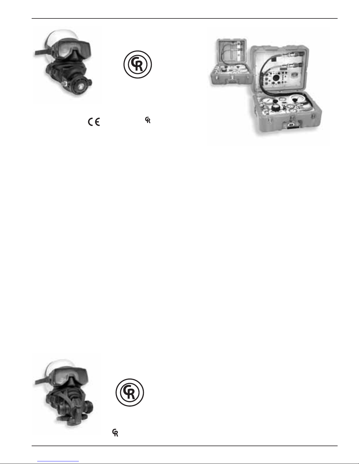
SuperMask M-48
C
O
M
M
E
R
C
I
A
L
L
Y
R
A
T
E
D
-
P
R
O
F
E
S
S
I
O
N
A
L
D
I
V
I
N
G
G
E
A
R
-
D
I
V
E
L
A
B
T
E
S
T
E
D
™
C
O
M
M
E
R
C
I
A
L
L
Y
R
A
T
E
D
-
P
R
O
F
E
S
S
I
O
N
A
L
D
I
V
I
N
G
G
E
A
R
-
D
I
V
E
L
A
B
T
E
S
T
E
D
™
™
w/ Scuba Pod
Kirby Morgan® 37 & 57
KMACS-5
w/ No Communications
approved and ™ marked
The SuperMask M-48 is an innovative new design
in a full-face mask. It provides the diver with all the
comfort of a full-face mask with the convenience of
changeable second st age regulators as well as the ability to use a snorkel wit hout having to remove the mask.
The mask is comprised of two major components,
the mask frame and the interchangeable lower pod.
The removable lower pod is a feature unique to the
SuperMask full-face mask. When diving, the pod is
easily removed and replaced on the mask, providing
the diver the capability to buddy-breathe, snorkel, use
an octopus or perform an “in water” gas switch.
With the pod sealed to the mask, the exible, silicone
pod cover allows the diver to quickly place the regulator mouthpiece into the mouth or dive with it free of
the mout h for com mun ications. With the mouthpie ce
in, the regulator may be used without the pod being
sealed to the mask.
The mask may also be used surface supplied when
used with the proper accessories. We are currently
developing several different pod congurations for
both open circuit and rebreather use. For further
information, see the Frequently Asked Questions
(FAQ) area on
our web site at www.KirbyMorgan.
com/FullFaceMasks/M48.html.
KMACS-5
w/ Communications
The Kirby Morgan Air Control System-5 (KMACS)
is a lightweight, portable control box for use in surface supplied air diving operations. The KMACS-5
controls the diver’s air supply, communications and
monitors the diver’s depth. It allows two divers clear
push-to-talk (two wire) or round robin (four wire)
communications. The KMACS-5 is also available
without communications.
The air supply can be either from a low-pressure
compressor or high-pressu re cylinders. T he adjustable
rst stage regulator reduces the high-pressure air and
supplies low pressure through the umbilical to the
diver’s breathing system.
High pressure yokes permit U.S. standard scuba cylinders or DIN equipped cylinders to be used. Lowpressure air supply ttings allow for a compressor to
be used as the primary air source.
A complete pneumo system with dual reading gauges
(both US Standard and Metric) is provided for each
diver’s air, as well as a shut-off/bleed system that uses
two high-pressure feed lines which allows changing
of used cylinders without interruption of the diving
operation. Optional shut off valves allow the isolation
of each diver’s air supply.
© ⅯⅯⅩⅢ Kirby Morgan Dive Systems, Inc. All rights reserved. Document #130108002 3
SuperMask M-48
w/ Rebreather pod
The Communication Set is a multipurpose intercommunication system that provides reliable and clear
communications between a topside operator (tender)
and one or more surface-supported divers, recompression chambers, or other submersible systems.
marked
Kirby Morgan® 37 & 57
1.3 Kirby Morgan Diving Helmets
All Kirby Morgan diving helmets and masks are
manufactured by Kirby Morgan Dive Systems, Inc.
(KMDSI). Each step of the manufacturing process is
carefully controlled to assure the customer of a high
quality, durable helmet that will function properly for
many years.
There are eight models of Kirby Morgan diving helmets currently in production. They a re the SuperLite
17B, (MK-21- U.S. Navy version), SuperLite
SuperLite
47, 57, and 77. All are
The SuperLite
®
27, and Kirby Morgan models 37, 37SS,
®
-17 A/B was rst developed in 1975
™
marked.
®
and quickly set a new standard for diving helmet
design. Many large and small commercial diving
companies, military organizations, scientic divers,
and public safety divers are successfully using this
design around the world. This helmet is
marked.
®
17C the
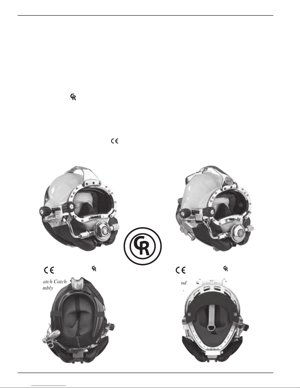
The SL-17 A/B helmet system consists primarily of
two major components: the neck dam/yoke assembly,
and t he helmet. To don the helmet, the diver rst slips
the a ngled neck dam wit h t he attached yoke over thei r
head. The helmet is lowered onto the diver’s head
with the help of a tender, then the yoke hinge tab is
hooked onto the alignment screw on the rear weight.
The neck clamp is then slipped onto the helmet and
locked. The locking system not only seals the neck
-
dam to the helmet but also secures the front of the
yoke, fastening the helmet to the diver’s head.
The SuperLite
®
-17A /B shares many common breath-
ing system parts with all Kirby Morgan helmets
and masks. The breathing system was man-tested
to 1600 FSW by the University of Pennsylvania and
approved by the U.S. Navy for surface-supplied diving to 190 FSW with air and 300 FSW with mixed
gas. It surpasses all requirements of all governing
agencies and it is approved for commercial diving
through out the world.
SuperLite® 17A/B
approved and ™ marked approved and ™ marked
Yoke and Latch Catch
Assembly
A
R
T
Y
E
L
D
L
A
I
C
R
E
M
M
O
C
D
E
T
S
E
T
B
A
L
E
-
P
R
O
F
E
S
S
I
O
N
A
L
D
I
V
I
N
G
G
V
E
I
A
D
R
-
™
Kirby Morgan
®
37
Neck Pad and
Sealed Pull Pins.
4 © ⅯⅯⅩⅢ Kirby Morgan Dive Systems, Inc. All rights reserved. Document #130108002
Other features that are common to all Kirby Morgan
C
O
M
M
E
R
C
I
A
L
L
Y
R
A
T
E
D
-
P
R
O
F
E
S
S
I
O
N
A
L
D
I
V
I
N
G
G
E
A
R
-
D
I
V
E
L
A
B
T
E
S
T
E
D
™
C
O
M
M
E
R
C
I
A
L
L
Y
R
A
T
E
D
-
P
R
O
F
E
S
S
I
O
N
A
L
D
I
V
I
N
G
G
E
A
R
-
D
I
V
E
L
A
B
T
E
S
T
E
D
™
helmets include:
* Face port and retainer ring
* Communications components
* Oral/nasal mask
* Nose block device
* Air train defogger
Kirby Morgan® 37 & 57
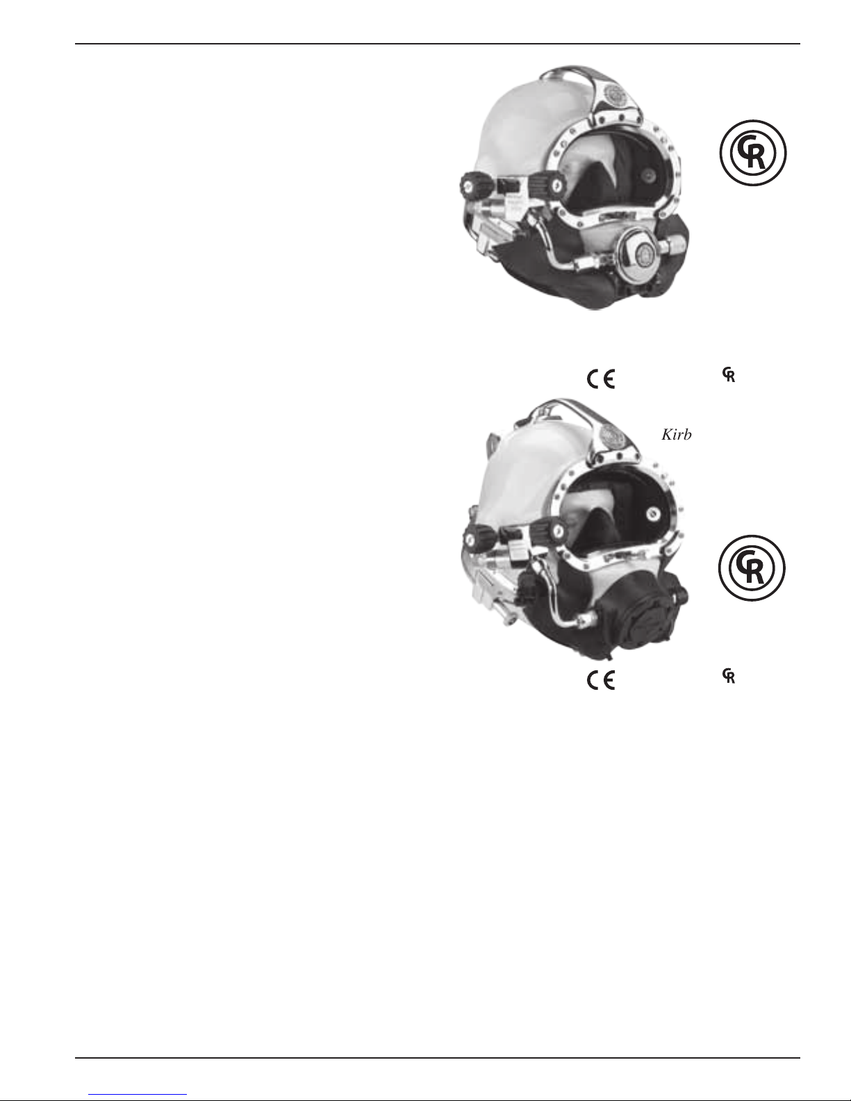
The Kirby Morgan
®
37 Commercial Diver’s Helmet
represents what we at Kirby Morgan consider to be
a turning point in modern diving helmet design. The
helmet consists of two major assemblies: the helmet
shell/helmet ring assembly and the neck dam/neck
ring assembly.
The helmet comes with the large tube SuperFlow
350 adjustable demand regulator which provides an
easier breathing gas ow during peak work output.
A quick change communications module is available
with either bare wire posts or a waterproof connector.
The helmet ring houses the sealed pull pins and
provides protection for the bottom end of the helmet.
The diver is also provided with an internally adjustable chin support. This custom t and balance seats
the helmet comfortably for long periods of time even
when working in the face down position.
The SuperLite
®
27® Commercial Diver’s Helmet has
all the same features of the KM37 on a smaller, low
volume shell design. This helmet is often preferred
by persons with smaller heads.
®
®
SuperLite
27
®
approved and ™ marked
Kirby Morgan® 47
®
The chrome plated machined brass helmet neck ring
houses the sealed pull pins and provides protection
for the bottom end of the helmet. Like the SL-17K,
37 and 17C, the diver is provided with an internally
adjustable chin support. This support, along with the
adjustable neck pad on the locking collar, gives the
diver a comfortable, secure, custom t.
The quick-cha nge communications module, available
with either bare wire posts or a waterproof connector,
allows for easy, efcient maintenance of the helmets
communications.
The helmet also features the SuperFlow
tube adjustable demand regulator. The helmet is
available in the umbilical over the shoulder, “B”
conguration only.
© ⅯⅯⅩⅢ Kirby Morgan Dive Systems, Inc. All rights reserved. Document #130108002 5
®
350 large
approved and ™ marked
The Kirby Morgan® 47 offers the ultimate in a high
performance breathing regulator. This helmet has an
entirely new breathing system, oral nasal mask, and
water ejection system. T he REX
®
Demand Valve, wit h
it’s fully adjustable balanced piston is a breakthrough
design that exceeds the requirements of all government or other testing agencies.
It has the best work-of-breathing performance when
compared to ANY other commercial diving helmet.
The Kirby Morgan 47 Dive Helmet has been tested
and meets or exceeds European CE requirements and
is fully commercially rated. In all other respects, this
helmet is nearly identical to the Kirby Morgan 37.

Kirby Morgan® 37 & 57
C
O
M
M
E
R
C
I
A
L
L
Y
R
A
T
E
D
-
P
R
O
F
E
S
S
I
O
N
A
L
D
I
V
I
N
G
G
E
A
R
-
D
I
V
E
L
A
B
T
E
S
T
E
D
™
™
marked
®
The Kirby Morgan® 57 helmet features our revolutionary new SuperFlow
®
450 Stainless Balanced
Regulator. It's machined from a stainless steel casting
for the ultimate in performance and reliability.
Like all KMDSI regulators on our helmets and
Band Masks
®
, we use only regulators that are specically designed for surface-supplied diving, that will
perform over the wide range of pressures delivered
by low pressure compressors. An ordinary SCUBA
regulator mounted on a diving helmet is not capable
of delivering the gas you need at heavy work loads.
This commercially rated fully diver adjustable regulator delivers all the breathing gas you might require
for the most demanding work underwater.
The Kirby Morgan
™
Valve
Exhaust System. It's recommended for div-
®
57 also includes our Quad
ing in biologically contaminated water, when you're
properly trained and equipped, using recommended
procedures. This new exhaust has exceptionally low
exhalation resistance that you must experience to
appreciate.
®
approved and ™ marked
The Kirby Morgan® 77 represents the rst in a new
generation of stainless steel diving helmets that provide an alternative for the diver who prefers a metal
helmet. The helmet features a stainless steel version
of our new REX
®
regulator, which offers the best
performance of any Kirby Morgan system.
It has the best work-of-breathing performance when
compared to ANY other commercial diving helmet.
The Kirby Morgan 77 Dive Helmet has been tested
and meets or exceeds European CE requirements and
is fully commercially rated.
The advantages of this all stainless steel helmet include the following:
• No renishing required if the surface is scratched
or gouged.
• Faster production of helmets for customer delivery.
B WARNING
Before attempting any diving in any
type of contaminated water, a complete diving and topside course in
hazardous materials emergencies
should be completed. The divers and
the topside team must be properly
trained and have the proper safety
equipment. All helmets and suits can
leak water under certain conditions.
Divers should use extreme caution
when diving in contaminated waters.
6 © ⅯⅯⅩⅢ Kirby Morgan Dive Systems, Inc. All rights reserved. Document #130108002
• Elim ination of th readed inserts for securing the port
retainer to the helmet shell.
• No need to remove the handle to remove the port
retainer.
• One piece sideblock includes both the free-ow valve
and the Emergency Gas System valve.
• The helmet ring is an integral part of the helmet.
Kirby Morgan® 37 & 57
®
approved and ™ marked
The Kirby Morgan
®
37SS features an all stainless
steel shell, as well as a stainless sideblock, helmet
ring, bent tube, handle, and other key components.
The SuperFlow
®
350 is standard on this helmet.
The K i rby Morgan 37SS featur es a quick change communications module, available with either bare wire
posts or a waterproof connector, and allows for easy,
efcient maintenance of the helmet's communications.
The advantages of this stainless steel helmet include
the following:
• Rugged helmet shell and other components
• No renishing required if the surface is scratched
or gouged
• Elimination of threaded inserts for securing port
retainer to helmet shell
© ⅯⅯⅩⅢ Kirby Morgan Dive Systems, Inc. All rights reserved. Document #130108002 7

Kirby Morgan® 37 & 57
WARNING
CAUTION
WARNING
Chapter 2
Description & Operational Specifications
Kirby Morgan 37 & 57
This manual is our effort to explain the operation, maintenance and use of the KM 37 & 57. We do
not herein make any effort to teach the principles of diving. It is our assumption the reader is a
qualified diver. We highly recommend that all divers should train, under controlled conditions, in
the use of any model of commercial diving helmet that they have not previously used or trained in,
prior to use on the job, until they have mastered the skills required to use their helmet correctly.
This section includes detailed descriptions of the
Kirby Morgan 37 and 57, as well as important operational specications. With the exception of the
regulators, all parts are interchangeable.
2.1 CR Marking
The helmet meets or excee ds all standards established
by Dive Lab of Panama City, Florida, and is CR
(Commercially Rated) rated with the SuperFlow
with SuperFlow
SuperFlow
L
A
I
C
R
E
M
M
O
C
-
D
E
T
S
E
T
B
A
L
E
®
350 non balanced reg ulator a nd with
®
450 balanced regulator.
A
R
T
Y
E
L
D
-
P
R
O
F
E
S
S
I
O
N
A
TM
L
D
I
V
I
N
G
G
E
A
V
I
R
D
-
TM
®
,
The helmet has been tested with air and CE
certicates for use with air up to 50 meters.
Compressed air must be compliant with the
EN 12021.
All the tables reporting the technical data
and the pressure of use are relative to compressed air.
2.2.1 CE Marking
On the frame of the helmet the CE mark is afxed.
EN250:2000
EN250/A1:2006
EN15333-1:2008
CLASS B
HELMET MODEL:
YEAR OF PRODUCTION:
CE Mark
KIRBY MORGAN
DIVE SYSTEMS, INC.
1430 Jason Way,
Santa Maria, CA 93455
2049
2.2 CE Certification
The helmet has been tested and conforms to the performance requirements as set forth in Annex II of
Directive 89/686/EEC and, as far as applicable, the
EN 250:2 000, EN 250/A1:2 006 and EN 15333-1:2008
(class B). It is fully CE marked with demand regulator SuperFlow
P/N 510-747.
Category of PPE: III
© ⅯⅯⅩⅢ Kirby Morgan Dive Systems, Inc. All rights reserved. Document #130108002 9
®
350 and oral nasals P/N 510-690 and
In the mark the data reported are the following:
1. the name and the address of the manufacturer;
2. harmonized reference standa rd: EN 250:2000, EN
250/A1:2006 and EN 15333-1;
3. Helmet model;
4. the year of production;
5. CE marking:
;
6. number of notied body.
The user cannot:
• remove the mark from the frame of the
helmet;
• modify or counter feit t he d ata reported
on the mark.
Kirby Morgan® 37 & 57
CAUTION
DANGER
The mark must be visible and legible
throu ghout th e l ife of the PPE . If t h e m a rk
deteriorates or is not legible the user
should contact the manufacturer.
2.2.2 Notified Body
The Notifying Body is Eurons-Modulo Uno
S.p.A.
Address: Via Cuorgne,
21-10156 Torino,
ITALY
Identication number: 2049
2.3 Product Specifications
Weight: KM 37 - 32.6 pounds
KM 57 - 31.6 pounds
Helmet Shell: Fiberglass, polyester resin, polyester gel
coat, and carbon bers
Control Knobs: Polyurethane
Lens: Clear polycarbonate
Neck Dam: Neoprene. Opt ional latex neck dam available.
O-Rings: Buna-N
Head Cushion: Nylon bag lled with #4 Polyester
foam
The recommended lubrication type for breathing
gas mixtures containing oxygen percentages greater
than 50% is Christo-Lube
Halocarbon
®
. Helmet gas train components being used
with gas mixtures containing less than 50% oxygen
can be lubricated with food grade silicone lubricant
such as Dow Corning
Never use aerosol-propelled sprays near the
face port of any Kirby Morgan diving helmet.
The propellant used in these aerosols can
invisibly damage the face port and cause it
to shatter on impact from any strong blow. If
the face port fails underwater, injury or death
may result.
If you have any questions regarding proper set-up,
operation, or maintenance of your Kirby Morgan 37
contact KMDSI (805) 928-7772 or at kmdsi@KirbyMorgan.com or Dive Lab Inc. (850) 235-2715 or at
Divelab@aol.com
®
, Krytox®, Tribolube® and
®
111.
2.4 Regulator Performance
2.4.1 SuperFlow® and SuperFlow® 350
Demand Regulators
The SuperFlow
®
350 non balanced regulator is the
standard demand regulator found on the SL-27, KM37 and KMB 18/28 Band Masks. NOTE: Pre Sep.
2004 KMB 28 plastic frames will only except the
smaller mount tube found on the SuperFlow
(non 350) regulator. The SuperFlow
CE marked and CR rated. The SuperFlow
®
350 is fully
®
450 SS
®
balanced regulator can be used on the SL-27, KM-37
and KMB-18/28 band Masks. Breathing performance
is greatly affected by the support equipment used, as
well as the supply pressure to the helmet or mask.
2.4.2 SuperFlow
The SuperFlow
®
450 Performance
®
450 is an all Stainless Steel regulator of a balanced design that offers a slightly higher
degre e of breath ing perform ance a nd extreme breathing rates, more than the non balanced SuperFlow
®
regulator.
2.5 Cage Code
The cage code for identifying KMDSI products for
U.S. government purposes is 58366.
2.6 Operational Specifications &
Limitations
This helmet meets or exceeds all performance requirements and is fully CE marked with the SuperFlow
and SuperFlow
®
350 non balanced regulator and is
CR rated by Dive Lab Inc. The helmet when equipped
with the SuperFlow
®
450 SS balanced regulator is CR
rated but not currently CE certied.
Every model of KMDSI helmets and masks undergo
extensive type testing to fully document the performance capability and required supply pressures when
using various umbilical and pressure combinations.
All users should take the time to become knowledgeable on supply requirements to insure proper performance and for the comfort and safety of the diver.
The required supply pressures for the KM-37 equipped
with either the SuperFlow
®
350 or SuperFlow® 450
regulators are listed in the appropriate supply pressure
tables in Appendix 3.
The supply pressures listed in the supply tables were
derived by breathing simulator trials. There are two
tables used for the SuperFlow
®
and SuperFlow® 350
regulators and two separate tables for the SuperFlow
450 regulator. It is important that users understand
how to use the tables. For further information on sup ply requ irements for the KM-37
®
or any K irby Morga n
®
®
10 © ⅯⅯⅩⅢ Kirby Morgan Dive Systems, Inc. All rights reserved. Document #130108002
helmet or mask check the Kirby Morgan website at
WARNING
DANGER
WARNING
WARNING
www.kirbymorgan.com.
-Umbilical minimum I.D. 3/8” (9.5 mm) of not more
than two sections, total length not to exceed 600 feet
(183m).
-Temperature Limitations: Use at water temperatures
below 33°F (1°C) requires the use of hot water shroud
PN# 525-100 and hot water to help prevent icing of
the demand regulator.
The demand regulator and side
block assemblies have a maximum design pressure of 250
psig (17.2 bar) over the ambient pressure, higher pressures
could lead to component failure
resulting in serious injury.
Decompression diving always involves the
risk of decompression sickness. Omitted
decompression due to a loss of the breathing gas supply or other accidents can cause
serious injury or death. Use of a Kirby Morgan
mask or helmet cannot prevent this type of
injury.
NOTE The Hot Water Shroud (Part #525-100) in
conjunction with hot water to the diver should be
used whenever diving operations are conducted
using HEO
at water temperatures less than 60°F
2
(15.56°C) for the comfort of the diver.
KMDSI further recommends that the shroud
be used in conjunction with hot water to the diver
whenever diving operations are conducted using
air or mixed gas, in waters colder than 33°F (1°C)
to reduce the possibility of demand regulator icing.
NOTE: Usually the greatest danger of demand
regulator icing will be encountered on deck when
the surrounding air temperature is less than 32°F
(0°C). This effect is primarily due to the refrigeration effect of breathing air pressure reduction, and
the addition of moisture from the divers exhalation
coming in contact with the topside air temperature.
If diving where the water temperature is 33°F
(1°C) or warmer but the topside air temperature
is below freezing, 32°F (0°C) icing of the demand
regulator is possible. To help eliminate the possibility of freezing on the surface, warm water should be
run over the exterior of the demand regulator prior
to water entry, if the hot water system is not used.
Kirby Morgan® 37 & 57
Only equipment certied and tested according to EN
250/E DI N 58 642 may be use d wit h the KM 37 helmet
when conducting diving operations in European EC
compliant countries.
The umbilical assembly should be composed of good
quality diving hose that meets industry standards.
Generally, gas hose will be married to the communications wire, pneumofathometer hose, and strength
member in a manner that will allow the strength
member to receive all the strain. There are also good
quality umbilicals available that are assembled at
the factory using a twisted method which does not
require marrying. Regardless of the system used, the
umbilical is the diver’s life line and should always be
of excellent quality and maintained carefully.
It is important for the user/diver to take
excessive currents into consideration. The
Quad Valve™ Exhaust PN#525-759 is now
standard on the KM-37/57. Unlike the old
latex double exhaust, the quad system is not
limited to a maximum depth of 150 FSW (46
msw) due to exhalation pressure.
If you have any questions regarding proper set-up,
operation, or maintenance of your Kirby Morgan
37/57 helmet contact KMDSI (850) 928-7772 or at
kmdsi@kirbymorgan.com or Dive Lab Inc. (850)
235-2715 or at Divelab@aol.com.
Gas systems used to supply Kirby Morgan
helmets and masks must be capable of supplying gas to the diver at the required pressure and flow rates as stated in the operational specifications. The use of unregulated
gas sources is extremely dangerous.
The use of standard SCUBA type regulators
is unacceptable, as there are no provisions
for adjusting the intermediate pressure to
the diver. Only proven systems that allow for
varying the gas supply pressure to the diver
should be used for umbilical diving.
2.7 Helmet Features
All Kirby Morgan diving helmets are manufactured
by hand. Each step of the manufacturing process is
carefully controlled to assure the customer a high
quality, durable helmet that will function properly.
© ⅯⅯⅩⅢ Kirby Morgan Dive Systems, Inc. All rights reserved. Document #130108002 11
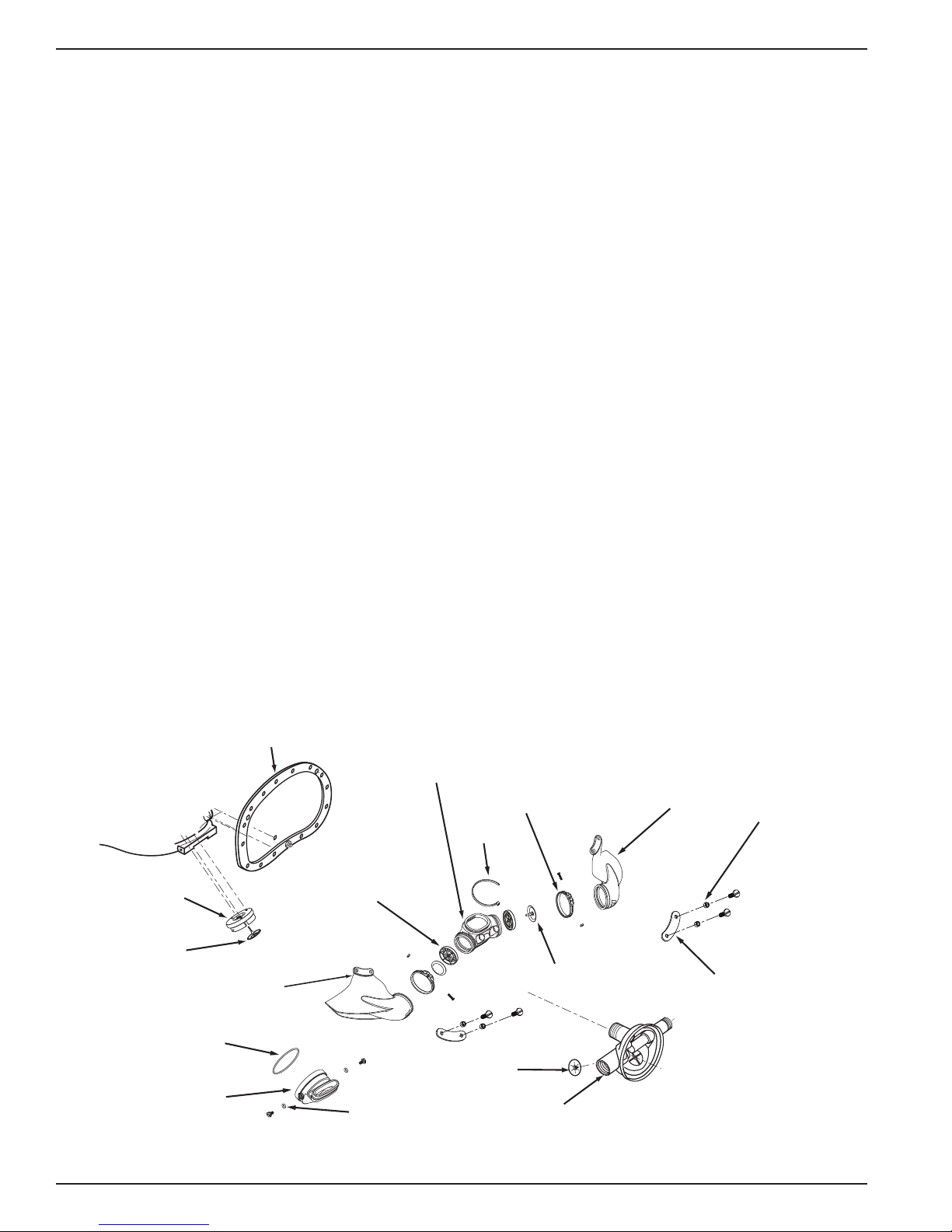
Kirby Morgan® 37 & 57
Quad exhaust
cover
Exhaust body
Water dump
valve
Port retainer
Exhaust valve
Regulator body
Starboard whisker wing
Exhaust main body
Whisker exhaust
valve insert
Tie wrap
O-ring
O-ring
Whisker clamp
Port whisker wing
Exhaust valve
Whisker
spacer
Kidney
plate
The KM 37 was developed in 2003 and the 57 was
developed in 2005. The goal was to bring together
all of the top design elements of the various Kirby
Morgan helmets and then rene the mix into what we
at KMDSI consider to be among the best in current
diving helmet design. The KM 37 and 57 take the
proven design features of our world famous Sup erLite
®
17 A/B and blends in many of the advanced design
features of the SuperLite
®
27. Add in some ne tuned
balance renements and you have two superb diving
helmets. Exemplifying our adherence to the highest
quality and proven superior work performance, the
KM 37 and 57 are the new working standards of the
commercial diving industry.
The KM 37 and 57 incorporate the in novative locking
system and com mun ications system of the SuperLite
27 onto a larger SuperLite
The 37 features the SuperF low
®
17 size berglass shell.
®
350 large tub e adjust-
®
able demand regulator which provides sup erb breathing gas ow during peak work output.
The helmet consists of two pieces: the helmet shell/
helmet ring and the neck dam/neck ring assembly. The
machined helmet ri ng houses the sea led pull pins and
locking collar, and provides protection for the bottom end of the helmet. It also mounts an externally
adjustable chin support. T his suppor t, along with the
adjustable neck pad on the locking collar, gives the
diver a secure, custom tailored t in the helmet. This
custom t and balance seats the helmet comfortably
for long periods of time even when working in the
face down position.
A quick change communications module, available
in either bare wire posts or a waterproof connector,
allows for easy, efcient maintenance of the communications in the helmet.
Both the KM 37 and 57 are congured to receive the
umbilical over the shoulder.
In the past, the optional Double Exhaust Syst em (Part
# 525-102) was available to reduce the possibility of
back ow of water and contaminants into the helmet.
This system has been used successfully for diving in
biologically contaminated environments for many
years. To further reduce the possibility of wat er int r usion regardless of the exhaust system being used, the
diver should avoid working in an inverted position.
The double exhaust was replaced by the Tri-Valve™
and subsequently by the Quad Valve
unique design of the Quad Valve
™
System. The
™
helps keep exhalation resistance low while maintaining excellent
watertight integrity.
12 © ⅯⅯⅩⅢ Kirby Morgan Dive Systems, Inc. All rights reserved. Document #130108002
The Quad Valve™ Exhaust
is standard equipment and
recommended for contaminated
water diving.
 Loading...