

Kirby Morgan 47 Operation And Maintenance Manual
WARNING
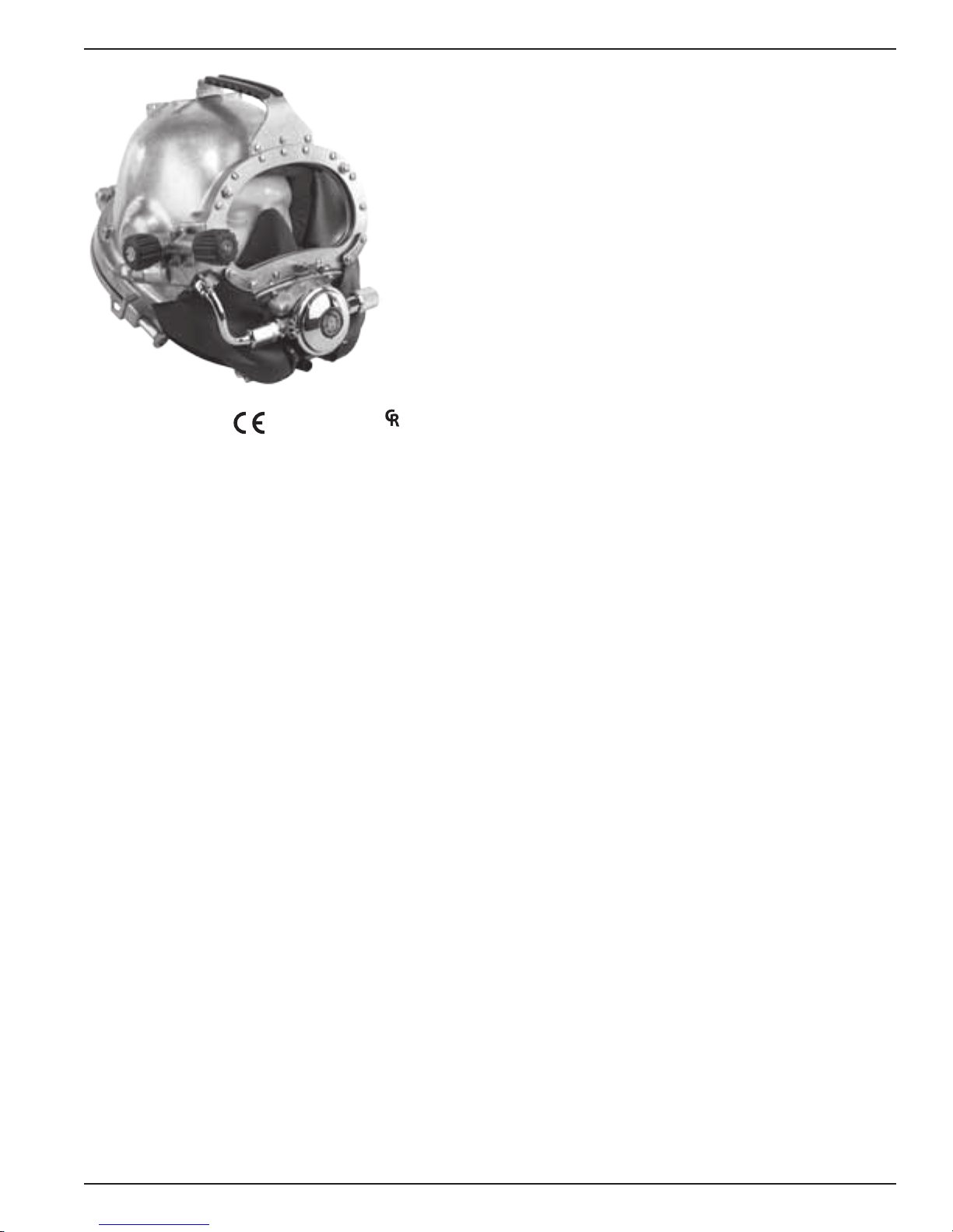
Kirby Morgan 47 Helmet
K
I
R
B
Y
M
O
R
G
A
N
D
I
V
E
S
Y
S
T
E
M
S
,
I
n
c
.
Operations and Maintenance Manual
KMDSI Part #100-070
Patented, Foreign Patents Pending, other patents apply.
Kirby Morgan Dive Systems, Inc.
1430 Jason Way
Santa Maria, CA 93455, USA
Telephone (805) 928-7772, FAX (805) 928-0342
E-Mail: kmdsi@KirbyMorgan.com, Web Site:www.KirbyMorgan.com
Manual prepared by Marine Marketing and Consulting, Dive Lab, Inc., and KMDSI.
NOTE: This manual is the most current for the Kirby Morgan 47 Helmet. It is page dated June 2012. Future changes
will be shown on page III and the changed pages will carry the date of change. Previous manuals may not reect
these updates.
Diving with compressed breathing gas is a hazardous activity. Even if you do everything
right there is always the danger that you may be killed or injured. No piece of diving
equipment can prevent the possibility that you may be killed or injured any time you
enter the water.
The Kirby Morgan 47 helmet meets or exceeds all performance and testing requirements of all government and non-government testing agencies throughout the world. They are CE approved. It is
approved for use on all commercial and military work underwater.
Kirby Morgan, SuperLite®, BandMask, Band Mask, KMB, KMB-Band Mask, DSI, Diving Systems International, EXO, REX®,
SuperFlow® and DECA are all registered trademarks of Kirby Morgan Dive Systems, Inc. Use of these terms to describe products
that are not manufactured by KMDSI is illegal.
The two dimensional images (such as photographs and illustrations) of our products are © copyrighted and trademarks of Kirby
Morgan Dive Systems, Inc. The three dimensional forms of our products are trademark, trade design and trade dress protected.
© ⅯⅯⅩⅡ Kirby Morgan Dive Systems, Inc. All rights reserved. This manual is made available for the express use of the owner of
this Kirby Morgan product. No part of this manual may be reproduced, stored in any retrieval system, or transmitted, or used in any
form or by any means, whether graphic, electronic, mechanical, photocopy, or otherwise by technology known or unknown, without
the prior written permission of Kirby Morgan Dive Systems, Inc.
Document Number 120614002

Kirby Morgan® 47
Warranty Information
Kirby Morgan Dive Systems, Inc. warrants every new mask, helmet, or KMAC Air Control System
to be free from defects in workmanship for a period of three hundred sixty ve (365) days from date
of purchase. This warranty covers all metal, berglass, and plastic parts. This warranty does NOT
cover rubber parts, communications components, or head cushions. In addition, due to the electrolytic nature of underwater cutting and welding, chrome plating cannot be warranted when the diver
engages in these activities.
Should any part become defective, contact the nearest authorized KMDSI dealer. If there is no
dealer in your area, contact KMDSI directly at (805) 928-7772. You must have a return authorization from KMDSI prior to the return of any item, Upon approval from KMDSI, return the defective part, freight prepaid, to the KMDSI plant. The part will be repaired or replaced at no charge as
deemed necessary by KMDSI.
This warranty becomes null and void if:
1) The product is not registered with KMDSI within ten (10) days of purchase.
2) The product has not been properly serviced and/or maintained according to the appropriate
KMDSI manual. In addition, the user is responsible to ensure that all product updates as
recommended by KMDSI have been performed.
3) Unauthorized modications have been made to the product.
4) The product has been abused or subjected to conditions which are unusual or exceed the
product’s intended service.
NOTE: Be sure to complete the enclosed warranty card and return it to KMDSI immediately. No
warranty claims will be honored without a satisfactorily completed warranty card on le at KMDSI.
II © ⅯⅯⅩⅡ Kirby Morgan Dive Systems, Inc. All rights reserved. Document #120614002
Kirby Morgan® 47
Record Of Changes
It is the responsibility of the owner of this product to register their ownership with Kirby Morgan Dive
Systems, Inc., by sending the warranty card provided. This card is to establish registration for any necessary
warranty work and provides a means of communication that allows KMDSI to contact the user regarding this
product. The user must notify KMDSI of any change of address by the user or sale of the product.
All changes or revisions to this manual must be recorded in this document to ensure that the manual
is up to date.
Change Number Date Description of Change
1 08/20/2008 Added: CE approval text to page 23 in chapter 2.
2 09/30/2008 Removed page number column on page number III.
Renumbered chapter 6 pages and subsequent chapters in table of contents.
®
REX
3 changed to REX® and image updated on page 14.
Added CE Certication text and logos on pages 19, 21 and 22.
Tables updated and moved to back on pages 23 and 24.
Renumbered Chapter 2 Sections
Image Updated page 28.
Updated Exploded view of REX® regulator on page 29.
Rearranged chapter 5 into 2 columns, pages 63.
Updated Image of special tools on page 64.
Updated text in chapter 6, 6.2.2 on page 65.
Updated Exploded view of REX® Exhaust System and changed REX® 3 to REX®
on page 73.
Replaced Whisker Clamps with Tie Wraps on pages 74-76.
Rearranged and updated Chapter 7, 7.8.1, 7.10 on page’s 92-96. and
page’s 101-104, and 106-107.
Rearranged Appendix 1: Torque Specications on page 145-146.
Added Appendix A2 on page 143.
Added Appendix 3 on page 145.
3 11/05/2008 Added D-Ring to Image on page 18.
Blowapart Image Updated with D-Ring on page 32, 38, and 123.
Text Updated on pages 61-62.
Text Updated on page 120.
Added Microphone Diagram on page 134.
Image Updated on page 135.
Appendix A1: Torque Specications updated on page 141.
4 2/19/2009 Page 131 8.15.3 Removal of Communications Assembly added communications
breakage text.
Page 131 8.15.4 Replacement of Communications Assembly added communications breakage warning.
© ⅯⅯⅩⅡ Kirby Morgan Dive Systems, Inc. All rights reserved. Document #120614002 III

Kirby Morgan® 47
WARNING
5 3/30/2009 Page 74 Section 7.3.2 Step 3: Changed Picture caption, 270 kg. cm to 17 Newton
6 11/06/2009 Chapter 2 Addition of CE Conforming Criteria.
7 08/19/2010 Updated knob images and diagrams.
8 04/11/2011 Updated earphones throughout manual
9 06/17/2011 Changed 61 meters to 67 meters in Appendix 3 Table 3 Topside High-Pressure
10 10/17/2011 Updated CE Identication Number to 2049 and corrected area code for Santa
11 06/14/2012 Updated copyright format
Meters.
Page 79 Section 7.4.4 Step 3 and 6: Changed 50 inch pounds to 35, 5.65 Newton
Meters to 4 and 40 inch pounds to 15.
Page 109 Section 8.4.2 Step 4: Changed 35 inch pounds to 20.
Page 118 Section 8.6.2 Step 14 and 16: Changed picture caption 16 kg.cm to 1.5
Newton Meters.
Page 120 Section 8.6.3 Step 9: Changed 16 kg. cm to 1.5 Newton Meters.
Page 123 Section 8.11.2 Step 3: Changed 35 inch pounds to 12 and 39 kg.cm to
1.3 Newton Meters.
Page 125 Section 35 inch pounds to 20 and 27 kg.cm to 2.25 Newton Meters.
Page 139 Torque Specications: Updated location numbers and added part # 555-
167 Bent Tube Assembly.
Regulator Settings for use with the Kirby Morgan REX® Regulator
Maria Ofce from 850 to 805 in Chapter 2
Diving with compressed breathing gas is a hazardous activity. Even if you do everything
right there is always the potential for serious injury or death. No one piece of diving
equipment can prevent the possibility that you may be injured or killed any time you
enter the water. We do not herein make any effort to teach the principles of diving. The
information in this manual is intended for users of Kirby Morgan helmets and persons
that maintain or service Kirby Morgan helmets.
IV © ⅯⅯⅩⅡ Kirby Morgan Dive Systems, Inc. All rights reserved. Document #120614002

Kirby Morgan® 47
Table Of Contents
Warranty Information �������������������������������������������������������������������������������� II
Record Of Changes
Denition of Signal Words Used in this Manual
Chapter 1 General Information KMDSI Products ����������������������������������� 1
1.1 Introduction
1.2 Full-Face Masks and Manifolds
1.3 Kirby Morgan Diving Helmets
Chapter 2 Description & Operational Specications Kirby Morgan 47 �� 9
2.1 CR Marking
2.2 CE Certication
2�2�1� CE Marking ��������������������������������������������������������������������������������� 9
2�2�2� Notied Body ������������������������������������������������������������������������������ 10
2.3 Other Marking ���������������������������������������������������������������������������������� 10
2.4 Product Specications �������������������������������������������������������������������������10
2.5 Regulator Performance ������������������������������������������������������������������������ 10
2�5�1 REX® Regulator ����������������������������������������������������������������������������� 10
2�5�2 Minimum Operating Temperature �����������������������������������������������������������10
2.6 Cage Code �������������������������������������������������������������������������������������� 10
2.7 Operational Specications & ����������������������������������������������������������������� 10
2.8 Helmet Features ��������������������������������������������������������������������������������11
2.9 General Description
2�9�1 Helmet Shell �������������������������������������������������������������������������������� 13
2�9�2 Gas Flow Systems �������������������������������������������������������������������������� 13
2�9�3 Emergency Gas Supply System (EGS) ������������������������������������������������������16
2�9�4 Helmet Attachment to the Diver ������������������������������������������������������������� 17
2�9�5 Sealing Arrangement ����������������������������������������������������������������������� 18
2�9�6 Reducing Carbon Dioxide ������������������������������������������������������������������ 19
2�9�7 Communications ���������������������������������������������������������������������������� 19
2�9�8 Equalizing the Middle Ear ������������������������������������������������������������������� 19
2�9�9 Face Port or Viewing Lens ������������������������������������������������������������������ 19
2.10 Accessories
2�10�1 Eye Protection for Welding ���������������������������������������������������������������� 19
2�10�2 Special Regulator Tools for REX® Regulator ����������������������������������������������� 20
2.11 Helmet Transport And Storage
2�11�1 Helmet Carrying Bag ���������������������������������������������������������������������� 21
2.12 Use of Kirby Morgan Original Replacement Parts
Chapter 3.0 Operating Instructions ����������������������������������������������������� 23
3.1 Introduction
3.2 Design Purpose
3.3 First Use of Your Kirby Morgan Diving Helmet
3.4 Initial Adjustments to Your Helmet
3�4�1 Head Cushion ������������������������������������������������������������������������������ 25
3�4�2 Trimming the Neck Dam �������������������������������������������������������������������� 25
3�4�3 Adjusting the Neck Pad ��������������������������������������������������������������������� 26
3.5 Pre Dress-In Procedure
3�5�1 Pre-Dive Visual Inspection ������������������������������������������������������������������27
���������������������������������������������������������������������������������III
�������������������������������������������������� X
�������������������������������������������������������������������������������������� 1
���������������������������������������������������������������� 2
������������������������������������������������������������������ 4
�������������������������������������������������������������������������������������� 9
���������������������������������������������������������������������������������� 9
���������������������������������������������������������������������������� 13
����������������������������������������������������������������������������������� 19
�������������������������������������������������������������� 20
����������������������������������������� 21
������������������������������������������������������������������������������������� 23
��������������������������������������������������������������������������������� 23
���������������������������������������������� 25
������������������������������������������������������������ 25
������������������������������������������������������������������������ 27
© ⅯⅯⅩⅡ Kirby Morgan Dive Systems, Inc. All rights reserved. Document #120614002 V

Kirby Morgan® 47
3.6 Preparing the Helmet for Diving���������������������������������������������������������������28
3�6�1 Clean Face Port ���������������������������������������������������������������������������� 28
3�6�2 Check Moving Parts ������������������������������������������������������������������������ 28
3�6�3 Check Communications �������������������������������������������������������������������� 28
3�6�4 One Way Valve Check ���������������������������������������������������������������������� 28
3.7 Emergency Gas System (EGS) ���������������������������������������������������������������� 29
3.8 Setting Up to Dive ������������������������������������������������������������������������������ 34
3�8�1 Flushing Out the Umbilical ������������������������������������������������������������������ 34
3�8�2 Connecting the Umbilical to the Helmet ���������������������������������������������������� 34
3�8�3 Opening the Breathing Gas Supply to the Helmet�������������������������������������������35
3�8�4 Fogging Prevention �������������������������������������������������������������������������35
3�8�5 Donning The Kirby Morgan Helmet ���������������������������������������������������������36
3�8�6 Testing the Breathing System ���������������������������������������������������������������39
3�8�7 Sealing Integrity Check ��������������������������������������������������������������������� 39
3�8�8 Adjust Regulator for Low Work Rates �������������������������������������������������������39
3.9 Removing the Helmet �������������������������������������������������������������������������� 40
3.10 Diving Procedures ����������������������������������������������������������������������������41
3�10�1 Standing By to Dive ����������������������������������������������������������������������� 41
3�10�2 Attaching the Umbilical to the Harness ���������������������������������������������������� 41
3�10�3 Diver Dons Helmet ������������������������������������������������������������������������ 41
3�10�4 Diver Check Gas Flow Systems ����������������������������������������������������������� 41
3�10�5 Communications Check ������������������������������������������������������������������� 41
3�10�6 Diver Ready ������������������������������������������������������������������������������� 41
3�10�7 Water Entry and Descent ������������������������������������������������������������������41
3.11 Emergency Procedures ����������������������������������������������������������������������42
3�11�1 Flooding ����������������������������������������������������������������������������������� 42
3�11�2 Inhalation Resistance ���������������������������������������������������������������������� 42
3�11�3 Gas Flow Stops ��������������������������������������������������������������������������� 42
3�11�4 Demand Regulator Free Flow ��������������������������������������������������������������43
3.12 Post Dive Procedures ������������������������������������������������������������������������44
3�12�1 Removing the Equipment ������������������������������������������������������������������ 44
3�12�2 Removing the Helmet ��������������������������������������������������������������������� 44
3�12�3 Storage of the Helmet Between Dives ����������������������������������������������������� 44
Chapter 4 Troubleshooting ������������������������������������������������������������������ 45
4.1 General ������������������������������������������������������������������������������������������ 45
4.2 Communication Malfunction ������������������������������������������������������������������ 45
4.3 One Way Valve Malfunction ������������������������������������������������������������������� 45
4.4 Side Valve Malfunction �������������������������������������������������������������������������46
4.5 Water Leakage Into Helmet �������������������������������������������������������������������46
4.6 Demand Regulator Malfunction ��������������������������������������������������������������� 47
4.7 Emergency Gas Supply Valve �����������������������������������������������������������������47
Chapter 5 Inspection and Maintenance ����������������������������������������������� 49
5.1 Routine Maintenance �������������������������������������������������������������������������� 49
5�1�1 Daily Pre-Dive Maintenance A2�3 �����������������������������������������������������������49
5�1�2 Daily Post Dive Maintenance A2�6 ���������������������������������������������������������� 49
5�1�3 Supervisors Equipment Checks A2�4 and A2�5 ��������������������������������������������� 49
5.2 Monthly Maintenance �������������������������������������������������������������������������� 49
5.3 Yearly Maintenance ���������������������������������������������������������������������������� 49
5�3�1 Overhaul/Inspection Checklist A2�1 ��������������������������������������������������������� 49
VI © ⅯⅯⅩⅡ Kirby Morgan Dive Systems, Inc. All rights reserved. Document #120614002

Kirby Morgan® 47
Chapter 6.0 General Preventative Maintenance ����������������������������������51
6.1 Introduction �������������������������������������������������������������������������������������51
6.2 Required tools, Sealing, Cleaning Agents, Lubrication
6�2�1 Component and Parts Cleaning ������������������������������������������������������������� 52
6�2�2 Component and Parts Lubrication ���������������������������������������������������������� 52
6�2�3 Teon® Tape �������������������������������������������������������������������������������� 53
6�2�4 RTV Sealant ��������������������������������������������������������������������������������53
6�2�5 Thread Locker ������������������������������������������������������������������������������53
6.3 General Cleaning & Inspection Procedures
6�3�1 O-ring Removal/Inspection/Cleaning and Lubrication ��������������������������������������� 54
6.3.1.1 O-ring Removal ��������������������������������������������������������������������������� 54
6.3.1.2 O-ring Inspection: ������������������������������������������������������������������������� 54
6.3.1.3 O-ring Reuse: ���������������������������������������������������������������������������� 54
6.3.2 General Cleaning Guidelines
6.3.2.1 Mild Soap Solution for General Cleaning and Leak Detector Use ������������������������������� 56
6.3.2.2 Acidic Cleaning Solution and Procedures ����������������������������������������������������56
6.3.2.3 Germicidal Cleaning Solutions and Procedure ������������������������������������������������56
6.4 Daily Maintenance
������������������������������������������������������������������������������ 57
���������������������������������������������������������������� 54
6.5 Monthly Maintenance (or between jobs)
6�5�1 Locking Collar Assembly & Helmet Ring ���������������������������������������������������� 58
6�5�2 Neck Dam Ring Assembly ������������������������������������������������������������������ 58
6�5�3 Head Cushion and Chin Cushion ����������������������������������������������������������� 59
6�5�4 Communications Inspection ���������������������������������������������������������������� 59
6�5�5 Lubricate Nose Block O-Rings ������������������������������������������������������������� 59
�������������������������������������������������� 53
����������������������������������������������������� 58
������������������������������������� 51
6.6 REX® Demand Regulator & Exhaust System Post Dive Cleaning & Sanitizing ����������� 60
6�6�1 Post Dive Disassembly ��������������������������������������������������������������������� 60
6�6�2 Sanitizing ����������������������������������������������������������������������������������� 61
6�6�3 Post Dive Reassembly ���������������������������������������������������������������������� 62
Chapter 7.0 Breathing System Maintenance and Repairs ��������������������63
7.1 Introduction �������������������������������������������������������������������������������������63
7.2 Torque Values ����������������������������������������������������������������������������������� 63
7.3 One Way Valve
7�3�1 Disassembly Of The One Way Valve �������������������������������������������������������� 63
7�3�2 Reassembly of the One Way Valve ���������������������������������������������������������� 64
7.4 Side Block Assembly �������������������������������������������������������������������������� 66
7�4�1 General ������������������������������������������������������������������������������������� 66
7�4�2 Removal of the Bent Tube ������������������������������������������������������������������ 66
7�4�3 Separating the Side Block Assembly from the Helmet Shell ��������������������������������66
7�4�4 Side Block Assembly Replacement �������������������������������������������������������� 68
7�5�2 Cleaning and Lubricating ������������������������������������������������������������������� 70
7.5 Defogger Valve ���������������������������������������������������������������������������������71
7�5�1 Disassembly of the Defogger Valve ���������������������������������������������������������71
7�5�3 Reassembly of the Defogger Valve ����������������������������������������������������������71
7.6 Emergency Valve Assembly
7�6�1 Disassembly of the Emergency Valve ������������������������������������������������������� 72
7�6�2 Cleaning and Lubricating ������������������������������������������������������������������� 72
7�6�3 Reassembly of Emergency Valve ����������������������������������������������������������� 73
7.7 Bent Tube Assembly
7�7�1 General ������������������������������������������������������������������������������������� 75
���������������������������������������������������������������������������������� 63
������������������������������������������������������������������� 72
��������������������������������������������������������������������������� 75
© ⅯⅯⅩⅡ Kirby Morgan Dive Systems, Inc. All rights reserved. Document #120614002 VII

Kirby Morgan® 47
7�7�2 Removal of the Bent Tube Assembly �������������������������������������������������������� 75
7�7�3 Inspection of Bent Tube Assembly ���������������������������������������������������������� 76
7�7�4 Reinstallation of the Bent Tube Assembly ��������������������������������������������������� 76
7.8 Demand Regulator & Exhaust System Overhaul �������������������������������������������� 77
7�8�1 System Disassembly ������������������������������������������������������������������������ 77
7.9 Cleaning REX
7�9�1 Precautions for Cleaning ��������������������������������������������������������������������82
7�9�2 Cleaning Instructions ����������������������������������������������������������������������� 82
®
Regulator Parts ��������������������������������������������������������������� 82
7.10 REX® Regulator Re-Assembly ��������������������������������������������������������������� 84
®
7.11 Testing the REX
7�11�1 REX® Adjustment Troubleshooting ��������������������������������������������������������� 90
Demand Regulator for Proper Adjustment �����������������������������90
7.12 Oral/Nasal Mask ������������������������������������������������������������������������������ 91
7�12�1 Oral/Nasal Removal ����������������������������������������������������������������������� 91
7�12�2 Inspection of Oral/Nasal ������������������������������������������������������������������� 91
7�12�3 Oral/Nasal Replacement ������������������������������������������������������������������� 91
7.13 Reinstalling the Regulator on the Helmet
��������������������������������������������������� 92
7.14 Overpressure Relief / Bleed Valve Overhaul Procedures ���������������������������������94
7�14�1 Overpressure Relief Valve ����������������������������������������������������������������� 94
7�14�2 Overpressure Relief Valve Disassembly and Cleaning ������������������������������������� 94
7�14�3 Overpressure Relief Valve Reassembly ���������������������������������������������������� 95
7�14�4 Overpressure Relief Valve Lift Check/Setting ���������������������������������������������� 95
Chapter 8 Corrective Maintenance ������������������������������������������������������97
8.1 General ������������������������������������������������������������������������������������������ 97
8.2 Helmet Shell Inspection������������������������������������������������������������������������97
8.3 Nose Block Assembly �������������������������������������������������������������������������� 98
8�3�1 Nose Block Assembly Removal ������������������������������������������������������������� 98
8�3�2 Nose Block Device Replacement ����������������������������������������������������������� 98
8.4 Handle and Weights ����������������������������������������������������������������������������99
8�4�1 Handle Removal ��������������������������������������������������������������������������� 99
8�4�2 Handle Replacement ����������������������������������������������������������������������� 99
8�4�3 Side Weight Removal ��������������������������������������������������������������������� 100
8�4�4 Weight Replacement ��������������������������������������������������������������������� 101
8�4�5 Top Weight Removal ��������������������������������������������������������������������� 101
8�4�6 Top Weight Replacement ����������������������������������������������������������������� 101
8.5 Face Port �������������������������������������������������������������������������������������� 102
8�5�1 General ����������������������������������������������������������������������������������� 102
8�5�2 Face Port, Port Retainer, and Nose Block Device Removal ������������������������������� 102
8�5�3 Face Port, Port Retainer and Nose Block Replacement ����������������������������������� 103
8�5�4 Special Note Regarding Ports ������������������������������������������������������������ 105
8�5�5 Port Retainer ������������������������������������������������������������������������������ 105
8.6 Neck Dam ������������������������������������������������������������������������������������ 106
8�6�1 Removal of the Neck Dam ���������������������������������������������������������������� 106
8�6�2 Neoprene Neck Dam Replacement ������������������������������������������������������� 106
8�6�3 Latex Neck Dam Replacement ������������������������������������������������������������ 109
8�6�4 Trimming a Latex Neck Seal �������������������������������������������������������������� 110
8.7 Neck Dam Pull Strap ������������������������������������������������������������������������� 111
8�7�1 Neck Dam Pull Strap Removal ������������������������������������������������������������ 111
8�7�2 Neck Dam Pull Strap Replacement ������������������������������������������������������� 111
8.8 Chin Strap
8�8�1 Chin Strap Removal ���������������������������������������������������������������������� 111
������������������������������������������������������������������������������������� 111
VIII © ⅯⅯⅩⅡ Kirby Morgan Dive Systems, Inc. All rights reserved. Document #120614002

Kirby Morgan® 47
8�8�2 Chin Strap Replacement ������������������������������������������������������������������ 111
8.9 O-Ring Seal Replacement ������������������������������������������������������������������ 112
8.10 Helmet Ring ��������������������������������������������������������������������������������� 113
8�10�1 Helmet Ring Repairs ��������������������������������������������������������������������� 113
8.11 Sealed Pull Pins
8�11�1 Removal of Sealed Pull Pins ������������������������������������������������������������� 113
8�11�2 Replacement of Sealed Pull Pins �������������������������������������������������������� 113
����������������������������������������������������������������������������� 113
8.12 Swing Tongue Catch ����������������������������������������������������������������������� 114
8�12�1 Disassembly of the Swing Tongue Catch ������������������������������������������������ 114
8�12�2 Reassembly of the Swing Tongue Catch ������������������������������������������������� 115
8.13 Locking Collar
8�13�1 Locking Collar Removal ����������������������������������������������������������������� 116
8�13�2 Locking Collar Disassembly ������������������������������������������������������������� 117
8�13�3 Locking Collar Reassembly ������������������������������������������������������������� 118
8.14 Head Cushion and Chin Cushion
8�14�1 Head Cushion Foam ��������������������������������������������������������������������� 119
8�14�2 Chin Cushion Foam ��������������������������������������������������������������������� 119
������������������������������������������������������������������������������� 116
���������������������������������������������������������� 119
8.15 Communications System ������������������������������������������������������������������� 120
8�15�1 General ���������������������������������������������������������������������������������� 120
8�15�2 Earphone Inspection �������������������������������������������������������������������� 120
8�15�3 Removal of Communications Assembly ������������������������������������������������� 121
8�15�4 Replacement of Communications Assembly ��������������������������������������������� 121
8�15�5 Microphone Replacement ��������������������������������������������������������������� 121
8�15�6 Earphone And Wire Assembly Replacement ��������������������������������������������� 122
8�15�7 Waterproof Connector ������������������������������������������������������������������� 123
8.15.7.1 Connector Removal �������������������������������������������������������������������� 123
8.15.7.2 Connector Replacement ���������������������������������������������������������������� 123
8�15�8 Terminal Connections in the Waterproof Connector ������������������������������������� 123
8�15�9 Communications Posts ����������������������������������������������������������������� 125
8.15.9.1 Communications Post Removal ��������������������������������������������������������� 125
8.15.9.2 Communications Post Replacement ����������������������������������������������������� 125
Chapter 9.0 Accessories for the Kirby Morgan 47 ����������������������������� 127
9.1 Introduction ����������������������������������������������������������������������������������� 127
9.2 Low Pressure Inator Hose ������������������������������������������������������������������ 127
9�2�1 Installation of the Low Pressure Inator Hose ��������������������������������������������� 127
9�3�1 Weld Lens Assembly Installation ���������������������������������������������������������� 128
9.5 Use of Quick Disconnect �������������������������������������������������������������������� 129
9.4 Weld Shield Assembly ����������������������������������������������������������������������� 129
9�4�1 Weld Shield Assembly Installation �������������������������������������������������������� 129
Table of Equivalents �������������������������������������������������������������������������� 131
Appendix 1: Torque Specications ���������������������������������������������������� 132
Note on Torque Specications ���������������������������������������������������������� 133
Checklist, Maintenance, and Pre-Dive Inspections ������������������������������������������� 133
Appendix A2 Maintenance and Inspection Procedures ���������������������� 134
Appendix 3 Supply Pressure Requirements & Tables ������������������������� 136
Appendix 3 Table 1 Work Rate Expressed as Respiratory Minute Volume (RMV)* ��������� 137
Appendix 3 Table 2 REX® Regulator Low-Pressure Compressor Supply Pressure
Requirements Table Continued* ���������������������������������������������������������������� 138
Appendix 3 Table 3 Topside High-Pressure Regulator Settings for use with the Kirby
© ⅯⅯⅩⅡ Kirby Morgan Dive Systems, Inc. All rights reserved. Document #120614002 IX
Kirby Morgan® 47
CAUTION
DANGER
WARNING
WARNING
WARNING
WARNING
WARNING
WARNING
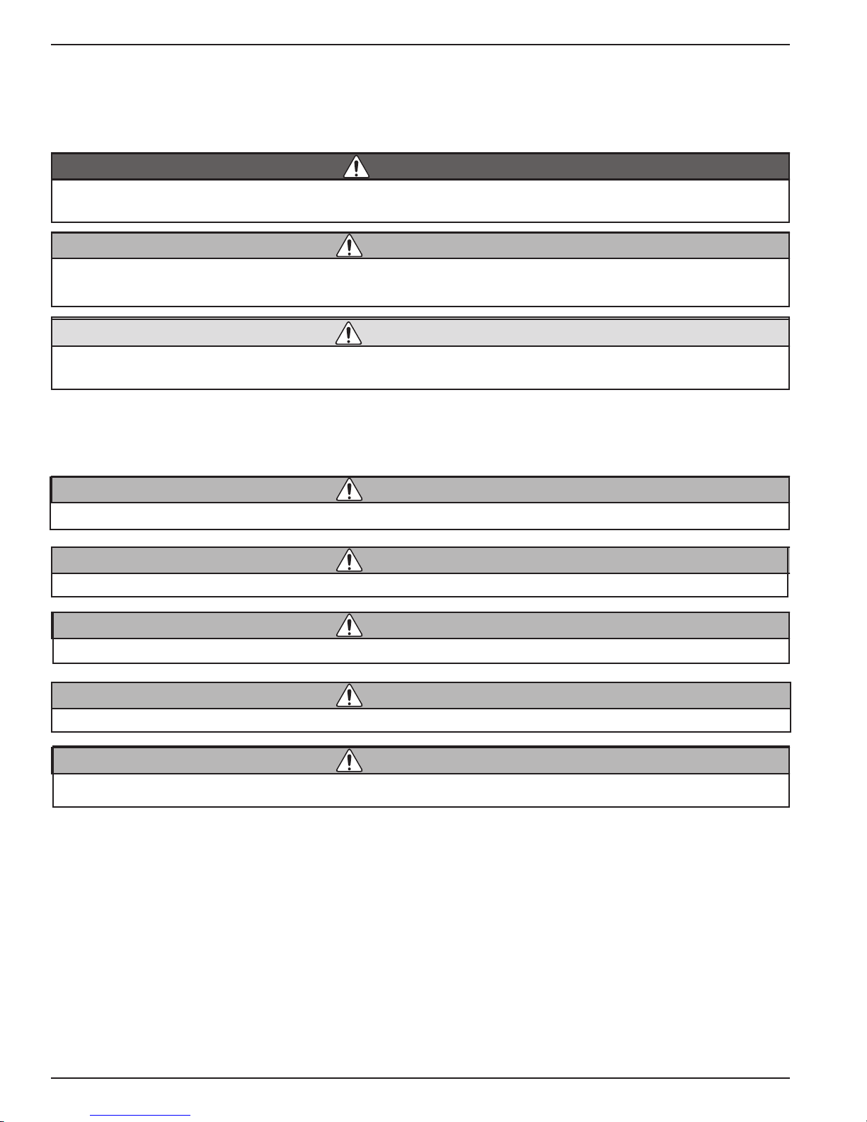
Definition of Signal Words Used in this Manual
For your protection, pay particular attention to items identied by signal words in this manual. These terms are identied
as, CAUTION, WARNING AND DANGER. It is especially important for you to read and understand these sections.
This word indicates an imminently hazardous situation, which if not avoided, could result in death or serious injury.
This word indicates a potentially hazardous situation, which, if not avoided, could result
in death or serious injury.
This word indicates a potentially hazardous situation, which if not avoided, may result in
minor or moderate injury. It may also be used to alert against unsafe practices.
If English is not your native language and you have any difculty understanding the language of any warnings as they
appear in the manual, please have them translated.
Este é um aviso importante. Queira mandá-lo traduzir.
Este es un aviso importante. Sirvase mandario traducir.
Quest è un avviso importante. Tradurlo.
Ceci est important. Veuillez traduire.
Diese Mitteilung ist wichtig. Bitte übersetzen lassen.
If you have any questions concerning this manual or the operation of your helmet, contact KMDSI (805) 928-7772 or
by Email at KMDSI@KirbyMorgan.com or Dive Lab Inc. (850) 235-2715 or at Divelab@aol.com
IMPORTANT: A word about this manual. We have tried to make this manual as comprehensive and factual
as possible. We reserve the right, however, to make changes at any time, without notice, in prices, colors, materials,
equipment, specications, models and availability. Since some information may have been updated since the time of
printing, please contact your local KMDSI dealer if you have any questions. To nd a dealer near you, please see the
Kirby Morgan web site, www.kirbymorgan.com. Periodically KMDSI Operations and Maintenance Manuals are reviewed. Any updates/changes will be posted on the KMDSI website and may be downloaded for insertion/correction.
Important Safety Information:
This Kirby Morgan diving helmet is intended for use by trained divers who have successfully completed a recognized
training course in surface supplied diving.
X © ⅯⅯⅩⅡ Kirby Morgan Dive Systems, Inc. All rights reserved. Document #120614002
Kirby Morgan® 47
WARNING
WARNING
WARNING
WARNING
WARNING
WARNING
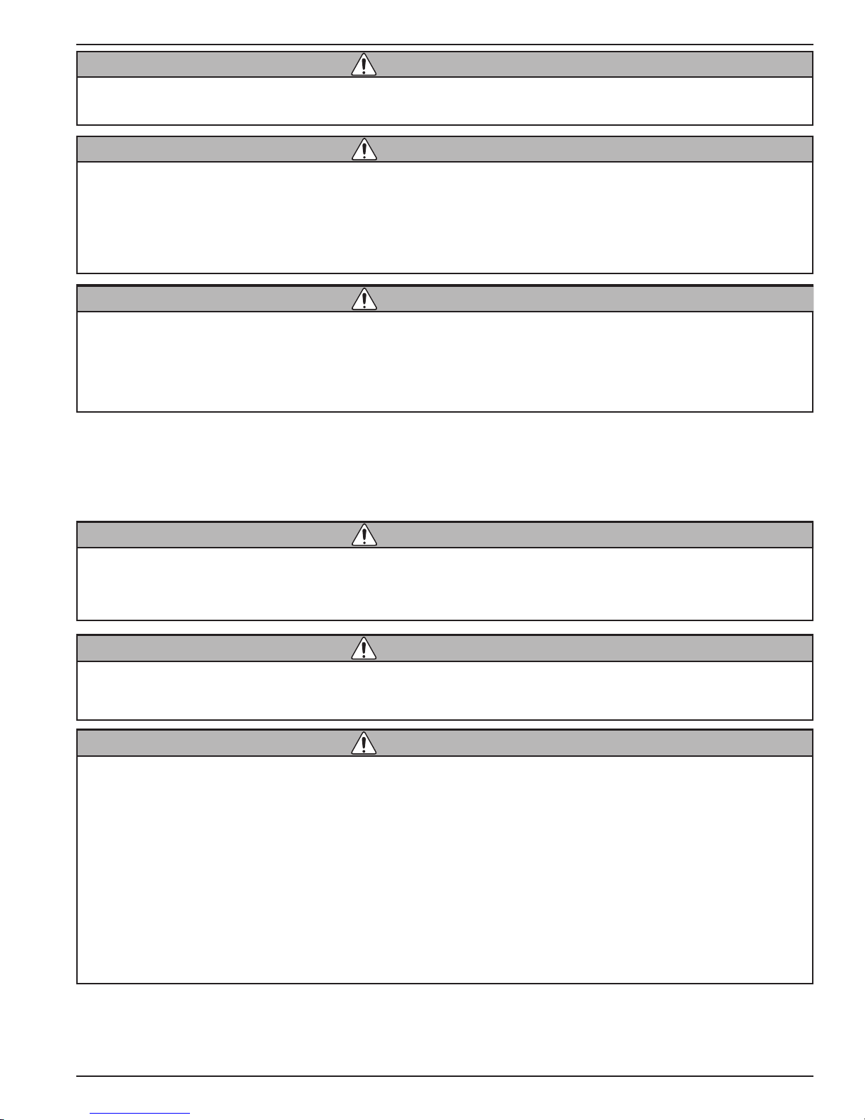
Follow all the instructions in this manual carefully and heed all safety precautions. Improper use of this diving helmet could result in serious injury or death.
Kirby Morgan Dive Systems, Inc. (KMDSI) warns all divers who use Kirby Morgan diving
helmets or masks to be sure to use only KMDSI original parts from a KMDSI authorized
dealer. Although other parts, O-rings and fittings may appear to fit your Kirby Morgan
diving helmet or mask, they may not be manufactured to the same standards maintained
by KMDSI. The use of any parts other than KMDSI original parts may lead to equipment
failure and accidents.
Diving in waters that are chemically, biologically, or radiologically contaminated is extremely hazardous. Although Kirby Morgan diving helmets may be adapted for use in
some contaminated environments, special training, equipment, and procedures are
necessary. Do not dive in a contaminated environment unless you have been thoroughly
trained and equipped for this type of diving.
Read this manual before using or maintaining the helmet, even if you have experience with other diving helmets. If
you have purchased the helmet new from a dealer, be sure to send in the warranty registration card so we may
keep you informed of any safety notices that affect this product. If you resell or loan this helmet to another diver,
be sure this manual accompanies the helmet and that the person reads and understands the manual. In addition to the
manual a log book should be used to log all repairs, maintenance and use.
Diving is a life threatening occupation. Even if you do everything right you can still be
killed or injured. None of the models of Kirby Morgan helmets or masks can prevent accidents, injuries or death due to improper training, poor-health, improper supervision,
improper job requirements, improper maintenance or acts of God.
This helmet was completely checked and should be ready to dive as it was shipped from
the factory. However, it is always the diver’s responsibility to check all the components
of the helmet prior to diving.
Any and all fiberglass repairs done to this helmet MUST be done by a KMDSI factory
trained repair facility. Painting is not recommended by KMDSI. Furthermore, many diving
companies will not allow painted helmets to be used because painting can mask previous fiberglass damage. KMDSI certified technicians are not responsible for certifying
helmets free from damage during annual overhauls.
Helmet shells can be re-gel coated by authorized/certified KMDSI trained technicians
that have received fiberglass training by KMDSI. Helmets that are to be painted for cosmetic purposes, should be first, certified free of fiberglass damage by an authorized
KMDSI technician certified in fiberglass repair. A log entry should be made in the helmet log that the helmet was free of damage prior to painting. Keep in mind other KMDSI
technicians can refuse to work on helmet shells that have previously been painted or
repaired by non KMDSI certified persons.
This manual is supplied to the original purchaser of this helmet. If you have any questions about the use of the helmet
or you need another copy of this manual, contact KMDSI or your nearest KMDSI dealer. It may also be downloaded
free from the KMDSI website at www.KirbyMorgan.com.
© ⅯⅯⅩⅡ Kirby Morgan Dive Systems, Inc. All rights reserved. Document #120614002 XI
Kirby Morgan® 47
WARNING
WARNING
WARNING
WARNING
WARNING
If you have any questions regarding the use, maintenance, or operation of this helmet, contact KMDSI at (805) 928-
7772, fax: (805) 928-0342, or e-mail: KMDSI@kirbymorgan.com.
Kirby Morgan masks and helmets are cleaned and lubricated for oxygen service when they come from the factory. However, if the helmet is used with an
oil lubricated air compressor, contamination with hydrocarbons may result.
If the breathing system in the helmet is exposed to hydrocarbons, it must be
cleaned for oxygen service and lubricated with oxygen safe lubricants before
using it again with breathing mixtures containing a high percentage of oxygen. If this is not done, res and explosions may result, exposing the user to
serious personal injury or death.
Components requiring lubrication, should only be lubricated with oxygen compatible lubricants such as Christo
Lube®, Fluorolube®, or Krytox®. Lubricants must be used sparingly and should not be mixed with other lubricants.
KMDSI helmets and masks are intended for underwater use only and should only be
used by qualified divers that have received proper training in the use of this type of
equipment. KMDSI helmets and masks should not be used or worn without the appropriate life support systems, such as air or gas supplies and support personnel as described in this manual.
KMDSI helmets and masks should never be used for motor sport racing, aviation /
space craft use, or for chemical warfare use. The helmet must never be used by persons
in poor physical condition, by persons with previous head, neck, or back injuries which
could be aggravated by its use. The helmet should not be used by persons under the influence of drugs or alcohol. Furthermore, infants, children, or persons under the age of
18 should never wear KMDSI helmets and masks. Failure to pay heed to the above could
result in serious injury or death.
Never use the helmet without first completing all pre-dive maintenance and set up pro-
cedures.
Do not use KMDSI masks or helmets in currents exceeding 3.0 knots Use in currents
greater than 3 knots may allow water to enter the exhaust valve, possibly causing regulator flooding.
Surface-supplied diving can be a strenuous activity. The Kirby Morgan 47 weighs approximately 30 lbs. KMDSI recommends that persons with a previous neck or back
injury seek professional medical approval prior to engaging in surface supplied diving
operations using the Kirby Morgan 47. Use of the Kirby Morgan 47 with a pre-existing
physical/medical condition may result in death or serious injury.
The information contained in this manual is intended to aid the user in optimizing the performance of this helmet.
The application of some of this information will depend on the diving situation and the use of associated equipment.
Many countries have specic laws and rules regarding commercial diving. It is important for the user to understand
the rules, regulations, and philosophy imposed by the governing, regulating bodies whenever using commercial diving
equipment.
XII © ⅯⅯⅩⅡ Kirby Morgan Dive Systems, Inc. All rights reserved. Document #120614002
Kirby Morgan® 47
WARNING
Whenever KMDSI helmets or masks are used in European Countries, which have adopted the C.E. certication programs, they must only be used with C.E. certied components. Diving operations should only be conducted within the
limits of the operational specications, and in accordance with the rules and regulations established by the governing
authority in the specic country or geographical location where the diving operations are being conducted. If you have
any questions concerning this manual or the operation of your helmet, contact KMDSI (805) 928-7772 or at kmdsi@
KirbyMorgan.com or Dive Lab Inc. (850) 235-2715 or at Divelab@aol.com
Always read the Material Safety Data Sheet (MSDS) for any chemical - adhesive, cleaning agent, or lubricant - used on your Kirby Morgan helmet. Some of these chemicals
may cause serious bodily injury or death if used improperly or without the proper personal protective equipment.
© ⅯⅯⅩⅡ Kirby Morgan Dive Systems, Inc. All rights reserved. Document #120614002 XIII
Kirby Morgan® 47
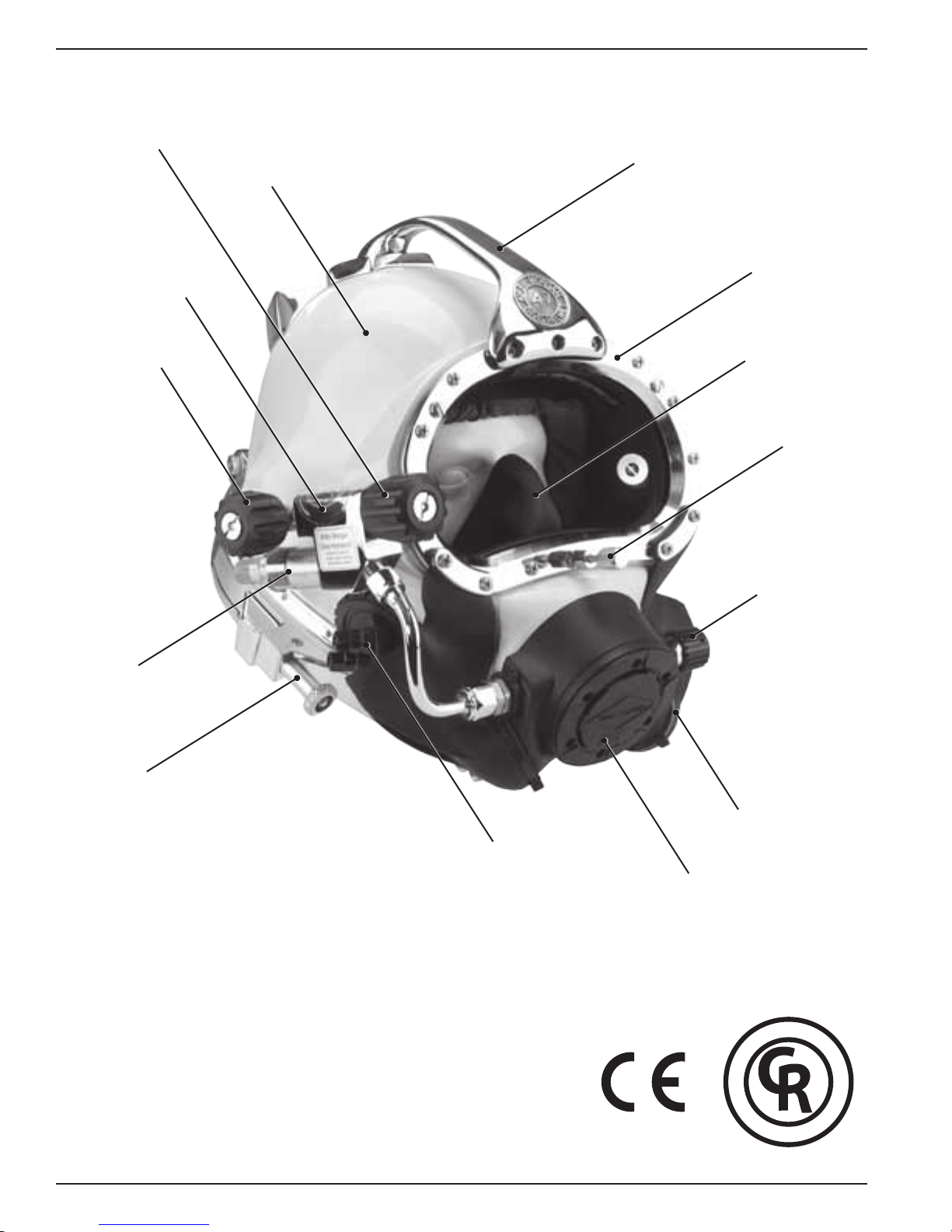
Defog Free Flow
Valve Knob
Sideblock
Handle
Helmet Shell
Port Retainer
EGS Valve
Non-Return Valve
Pull Pin
Oral Nasal Mask
Equalization Device
Regulator Adjustment
Knob
The Kirby Morgan® 47 helmet
XIV © ⅯⅯⅩⅡ Kirby Morgan Dive Systems, Inc. All rights reserved. Document #120614002
Communications
Module
®
REX
Exhaust
System
Purge Button
R
E
M
M
O
C
D
E
T
S
E
T
B
A
R
T
Y
E
L
D
L
A
I
C
A
L
E
-
P
R
O
F
E
S
S
I
O
N
A
L
D
I
V
I
N
G
G
V
E
I
A
D
R
-
™

Kirby Morgan® 47
STOP!
BEFORE GOING FURTHER-
This manual will refer to location numbers in specic drawings, or in the exploded view, which is
in the back of this manual. These numbers are called “location” numbers. They are used to nd
the referred to parts in the drawings in this manual only. They are not the part number. Next to
the exploded drawing is a list of the “location” numbers that match the Kirby Morgan part numbers along with the name of the part. Always check the part number when ordering to make sure
it is correct. When ordering, always specify the helmet model number and serial number as well.
Chapter 1
General Information KMDSI Products
1.1 Introduction
The Kirby Morgan Corporation was started in 1965.
The copper and brass “Heavy Gear” or “Standard
Dress” helmets wer e the rst hel mets manufactu red by
the company. Over the years Kirby Morgan designed,
manufactured and sold many different helmets and
masks for commercial divers.
Staying active in commercia l d iving has contributed to
the successful design innovations of KMDSI products.
This may be the primary reason for the acceptance of
our designs by professional divers.
Bev Morgan has designed more than fty-seven diving hel mets a nd over 40 diving masks. All employees
of KMDSI participate as part of the Kirby Morgan
design team. It would not be possible for us to supply
the commercial, military, scientic, and public service
diving industries with our equipment, wit hout the team
of people that make up Kirby Morgan Dive Systems,
Inc. (KMDSI)
We feel it is important for the reader to understand
that we at KMDSI consider ourselves as only part
of the process along the path in diving equipment
design. We welcome all input from our customers.
The thinking of many good divers, diving equipment
engineers, d iving medical specia lists, diving organ ization administrators and their supporting personnel has
contributed to the current state of the art of diving.
Each piece of gear we manufacture has in it some of
the thinking of those who have gone before us. To
all those people who gave something of themselves
to the men and women who work underwater, we
express a thank you.
We have a strong commitment to providing the best
diving equipment and service possible. This thinking
has been the policy of Kirby Morgan Dive Systems,
Bev Morgan, Chairman of the Board
Kirby Morgan Dive Systems, Inc.
Inc. and we will continue to take this approach to
our work.
Our extensive dealer network makes it easy to obtain
genuine Kirby Morgan replacement parts, as well as
technical assistance worldwide.
KMDSI has always concentrated on designing and
manufacturing diving equipment that allows most
repairs, inspections, and all routine maintenance to
be performed by the user. Most routine preventative
and corrective maintenance can be accomplished by
the user utilizing this manual, the KMDSI Tool Kit
(P/N 525-620) and common hand tools. Technician
training is available through Dive Lab Inc. Information can be obtained on line at www.divelab.com or
by telephone at 850-235-2715.
© ⅯⅯⅩⅡ Kirby Morgan Dive Systems, Inc. All rights reserved. Document #120614002 1
Kirby Morgan® 47
C
O
M
M
E
R
C
I
A
L
L
Y
R
A
T
E
D
-
P
R
O
F
E
S
S
I
O
N
A
L
D
I
V
I
N
G
G
E
A
R
-
D
I
V
E
L
A
B
T
E
S
T
E
D
™
C
O
M
M
E
R
C
I
A
L
L
Y
R
A
T
E
D
-
P
R
O
F
E
S
S
I
O
N
A
L
D
I
V
I
N
G
G
E
A
R
-
D
I
V
E
L
A
B
T
E
S
T
E
D
™
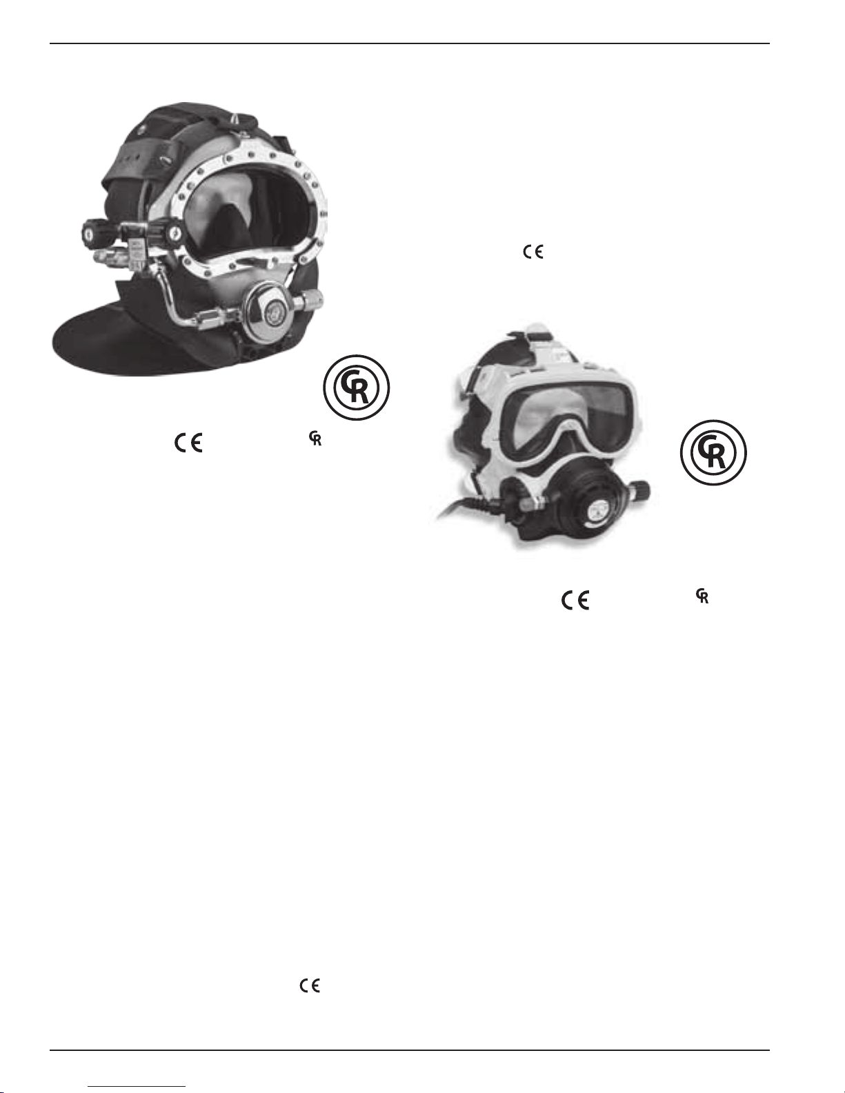
1.2 Full-Face Masks and Manifolds
KMB® 18 A/B
approved and ™ marked
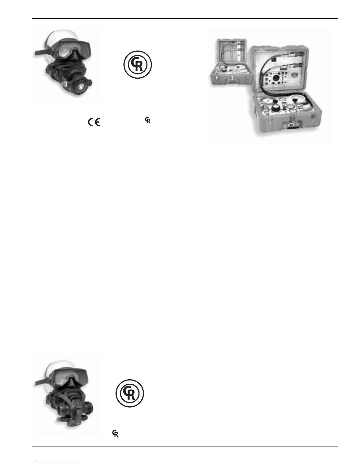
The EXO Full Face Mask is designed for both
surface supplied and scuba diving. By enclosing the
divers eyes, nose and mouth, the EXO permits nearly
normal speech when used in conjunction with most
wireless, and all hard wire underwater communication systems.
The EXO BR (BALANCED REGULATOR) shown
here is designed to meet or exceed recommended
performance goals in both scuba and surface supplied
modes and is
approved. It meets and surpasses
European standards for regulator performance.
The KMB 18B Band Mask frame is constructed of
hand laid berglass. The head harness is a molded,
strong tear resistant neoprene rubber.
The hood, which attaches to the mask frame with
welded stainless steel bands, provides warmth for the
divers head as well as pockets for the earphones. The
communications connections can be either a male
waterproof plug in type or bare wire posts. Both this
mask and the KMB 28B feature the new Tri-Valve™
Exhaust System.
The KMB 28B Band Mask (not shown) is very similar to the KMB 18, with many parts on the KMB 18B
being interchangeable wit h the KMB 28B. The major
difference between the 18 and 28 is the material of the
mask frame itself. The KMB 18 has a berglass frame
(yellow) while the KMB 28B frame is an extremely
durable injection molded plastic (black).
Other differences include:
1) The main exhaust body of the KMB 28 is part of the
frame itself and uses a #545-041 main exhaust cover
2) no comfort insert is required on the 28
3) the face ports for the 18 and the 28 differ slightly
in size.
EXO® BR
approved and ™ marked
The Balanced Regulator helps reduce the work of
breathing for the diver by balancing the i ntermediate
air pressure against the valve sealing pressure inside
the regulator. This enables the regulator to instantly
adjust to changes in line pressure. The balanced
regulator is adjustable for a wide range of intermediate pressures between 90 PSIG – 250 over ambient
pressure (6.2 – 17 bar).
Both models have a modular communications design that permits rapid and simple maintenance. The
optional Hard Shell provides surfaces for mounting
lights, cameras etc.
Both the KMB 18 and KMB 28 are
2 © ⅯⅯⅩⅡ Kirby Morgan Dive Systems, Inc. All rights reserved. Document #120614002
approved.
SuperMask M-48
C
O
M
M
E
R
C
I
A
L
L
Y
R
A
T
E
D
-
P
R
O
F
E
S
S
I
O
N
A
L
D
I
V
I
N
G
G
E
A
R
-
D
I
V
E
L
A
B
T
E
S
T
E
D
™
C
O
M
M
E
R
C
I
A
L
L
Y
R
A
T
E
D
-
P
R
O
F
E
S
S
I
O
N
A
L
D
I
V
I
N
G
G
E
A
R
-
D
I
V
E
L
A
B
T
E
S
T
E
D
™
™
w/ Scuba Pod
Kirby Morgan® 47
KMACS-5
w/ No Communications
approved and ™ marked
The SuperMask M-48 is an innovative new design
in a full-face mask. It provides the diver with all the
comfort of a full-face mask with the convenience of
changeable second st age regulators as well as the ability to use a snorkel wit hout having to remove the mask.
The mask is comprised of two major components,
the mask frame and the interchangeable lower pod.
The removable lower pod is a feature unique to the
SuperMask full-face mask. When diving, the pod is
easily removed and replaced on the mask, providing
the diver the capability to buddy-breathe, snorkel, use
an octopus or perform an “in water” gas switch.
With the pod sealed to the mask, the exible, silicone
pod cover allows the diver to quickly place the regulator mouthpiece into the mouth or dive with it free of
the mout h for com mun ications. With the mouthpie ce
in, the regulator may be used without the pod being
sealed to the mask.
The mask may also be used surface supplied when
used with the proper accessories. We are currently
developing several different pod congurations for
both open circuit and rebreather use. For further
information, see the Frequently Asked Questions
(FAQ) area on
our web site at www.KirbyMorgan.
com/FullFaceMasks/M48.html.
KMACS-5
w/ Communications
The Kirby Morgan Air Control System-5 (KMACS)
is a lightweight, portable control box for use in surface supplied air diving operations. The KMACS-5
controls the diver’s air supply, communications and
monitors the diver’s depth. It allows two divers clear
push-to-talk (two wire) or round robin (four wire)
communications. The KMACS-5 is also available
without communications.
The air supply can be either from a low-pressure
compressor or high-pressu re cylinders. T he adjustable
rst stage regulator reduces the high-pressure air and
supplies low pressure through the umbilical to the
diver’s breathing system.
High pressure yokes permit U.S. standard scuba cylinders or DIN equipped cylinders to be used. Lowpressure air supply ttings allow for a compressor to
be used as the primary air source.
A complete pneumo system with dual reading gauges
(both US Standard and Metric) is provided for each
diver’s air, as well as a shut-off/bleed system that uses
two high-pressure feed lines which allows changing
of used cylinders without interruption of the diving
operation. Optional shut off valves allow the isolation
of each diver’s air supply.
© ⅯⅯⅩⅡ Kirby Morgan Dive Systems, Inc. All rights reserved. Document #120614002 3
SuperMask M-48
w/ Rebreather pod
The Communication Set is a multipurpose intercommunication system that provides reliable and clear
communications between a topside operator (tender)
and one or more surface-supported divers, recompression chambers, or other submersible systems.
marked
Kirby Morgan® 47
1.3 Kirby Morgan Diving Helmets
All Kirby Morgan diving helmets and masks are
manufactured by Kirby Morgan Dive Systems, Inc.
(KMDSI). Each step of the manufacturing process is
carefully controlled to assure the customer of a high
quality, durable helmet that will function properly for
many years.
There are eight models of Kirby Morgan diving helmets currently in production. They a re the SuperLite
17B, (MK-21- U.S. Navy version), SuperLite
SuperLite
47, 57, and 77. All are
The SuperLite
®
27, and Kirby Morgan models 37, 37SS,
®
-17 A/B was rst developed in 1975
™
marked.
®
and quickly set a new standard for diving helmet
design. Many large and small commercial diving
companies, military organizations, scientic divers,
and public safety divers are successfully using this
design around the world. This helmet is
marked.
®
17C the
The SL-17 A/B helmet system consists primarily of
two major components: the neck dam/yoke assembly,
and t he helmet. To don the helmet, the diver rst slips
the a ngled neck dam wit h t he attached yoke over thei r
head. The helmet is lowered onto the diver’s head
with the help of a tender, then the yoke hinge tab is
hooked onto the alignment screw on the rear weight.
The neck clamp is then slipped onto the helmet and
locked. The locking system not only seals the neck
-
dam to the helmet but also secures the front of the
yoke, fastening the helmet to the diver’s head.
The SuperLite
®
-17A / B shares many common breath-
ing system parts with all Kirby Morgan helmets
and masks. The breathing system was man-tested
to 1600 FSW by the University of Pennsylvania and
approved by the U.S. Navy for surface-supplied diving to 190 FSW with air and 300 FSW with mixed
gas. It surpasses all requirements of all governing
agencies and it is approved for commercial diving
through out the world.
SuperLite® 17A/B
approved and ™ marked approved and ™ marked
Yoke and Latch Catch
Assembly
A
R
T
Y
E
L
D
L
A
I
C
R
E
M
M
O
C
D
E
T
S
E
T
B
A
L
-
P
R
O
F
E
S
S
I
O
N
A
L
D
I
V
I
N
G
E
G
V
E
I
A
D
R
-
™
Kirby Morgan
®
37
Neck Pad and
Sealed Pull Pins.
4 © ⅯⅯⅩⅡ Kirby Morgan Dive Systems, Inc. All rights reserved. Document #120614002
Other features that are common to all Kirby Morgan
C
O
M
M
E
R
C
I
A
L
L
Y
R
A
T
E
D
-
P
R
O
F
E
S
S
I
O
N
A
L
D
I
V
I
N
G
G
E
A
R
-
D
I
V
E
L
A
B
T
E
S
T
E
D
™
C
O
M
M
E
R
C
I
A
L
L
Y
R
A
T
E
D
-
P
R
O
F
E
S
S
I
O
N
A
L
D
I
V
I
N
G
G
E
A
R
-
D
I
V
E
L
A
B
T
E
S
T
E
D
™
helmets include:
* Face port and retainer ring
* Communications components
* Oral/nasal mask
* Nose block device
* Air train defogger
Kirby Morgan® 47
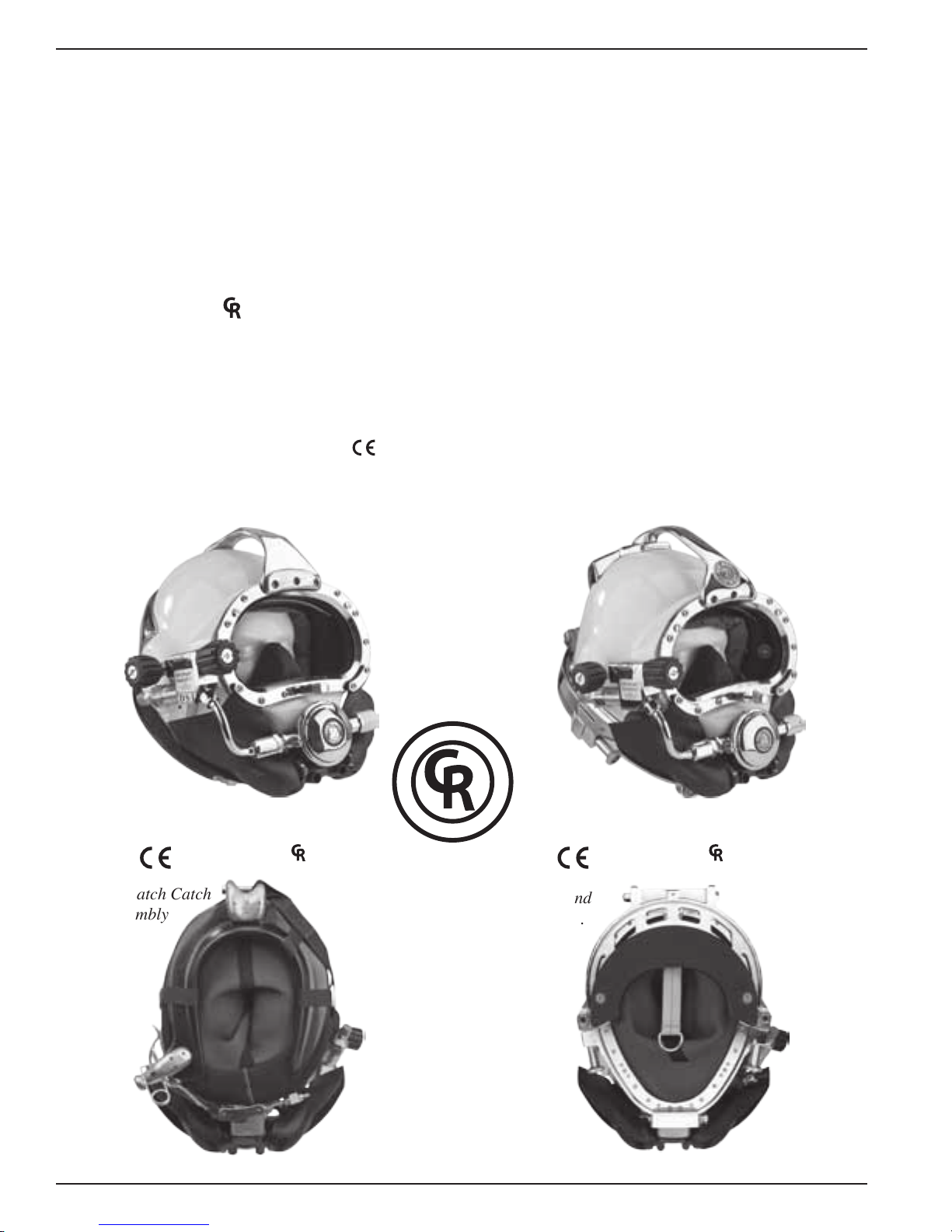
The Kirby Morgan
®
37 Commercial Diver’s Helmet
represents what we at Kirby Morgan consider to be
a turning point in modern diving helmet design. The
helmet consists of two major assemblies: the helmet
shell/helmet ring assembly and the neck dam/neck
ring assembly.
The helmet comes with the large tube SuperFlow
®
350 adjustable demand regulator which provides an
easier breathing gas ow during peak work output.
A quick change communications module is available
with either bare wire posts or a waterproof connector.
The helmet ring houses the sealed pull pins and
provides protection for the bottom end of the helmet.
The diver is also provided with an internally adjustable chin support. This custom t and balance seats
the helmet comfortably for long periods of time even
when working in the face down position.
The SuperLite
®
27® Commercial Diver’s Helmet has
all the same features of the KM37 on a smaller, low
volume shell design. This helmet is often preferred
by persons with smaller heads.
®
SuperLite
27
®
approved and ™ marked
Kirby Morgan® 47
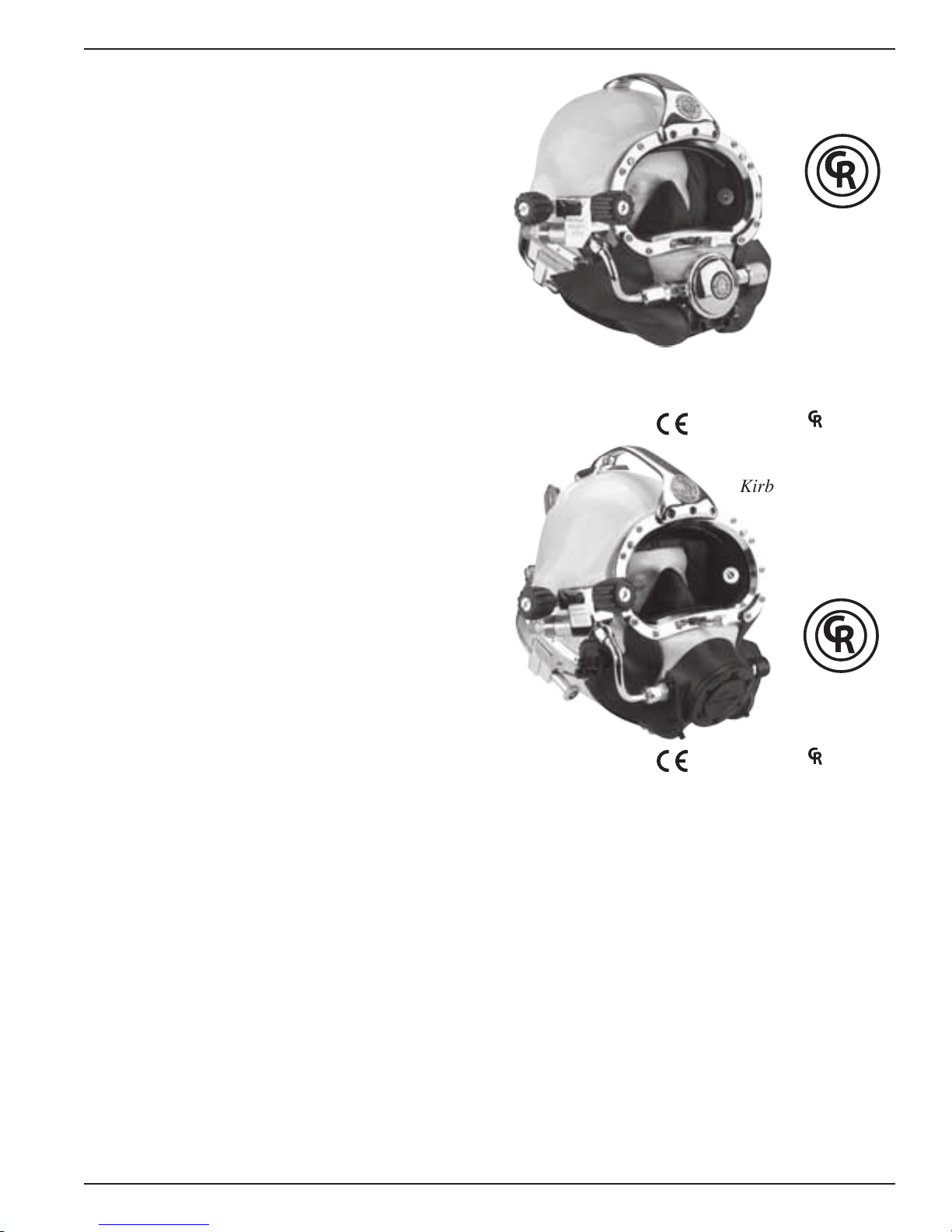
®
The chrome plated machined brass helmet neck ring
houses the sealed pull pins and provides protection
for the bottom end of the helmet. Like the SL-17K,
37 and 17C, the diver is provided with an internally
adjustable chin support. This support, along with the
adjustable neck pad on the locking collar, gives the
diver a comfortable, secure, custom t.
The quick-cha nge communications module, available
with either bare wire posts or a waterproof connector,
allows for easy, efcient maintenance of the helmets
communications.
The helmet also features the SuperFlow
tube adjustable demand regulator. The helmet is
available in the umbilical over the shoulder, “B”
conguration only.
© ⅯⅯⅩⅡ Kirby Morgan Dive Systems, Inc. All rights reserved. Document #120614002 5
®
350 large
approved and ™ marked
The Kirby Morgan® 47 offers the ultimate in a high
performance breathing regulator. This helmet has an
entirely new breathing system, oral nasal mask, and
water ejection system. T he REX
®
Demand Valve, wit h
it’s fully adjustable balanced piston is a breakthrough
design that exceeds the requirements of all government or other testing agencies.
It has the best work-of-breathing performance when
compared to ANY other commercial diving helmet.
The Kirby Morgan 47 Dive Helmet has been tested
and meets or exceeds European CE requirements and
is fully commercially rated. In all other respects, this
helmet is nearly identical to the Kirby Morgan 37.
Kirby Morgan® 47
C
O
M
M
E
R
C
I
A
L
L
Y
R
A
T
E
D
-
P
R
O
F
E
S
S
I
O
N
A
L
D
I
V
I
N
G
G
E
A
R
-
D
I
V
E
L
A
B
T
E
S
T
E
D
™
™
marked
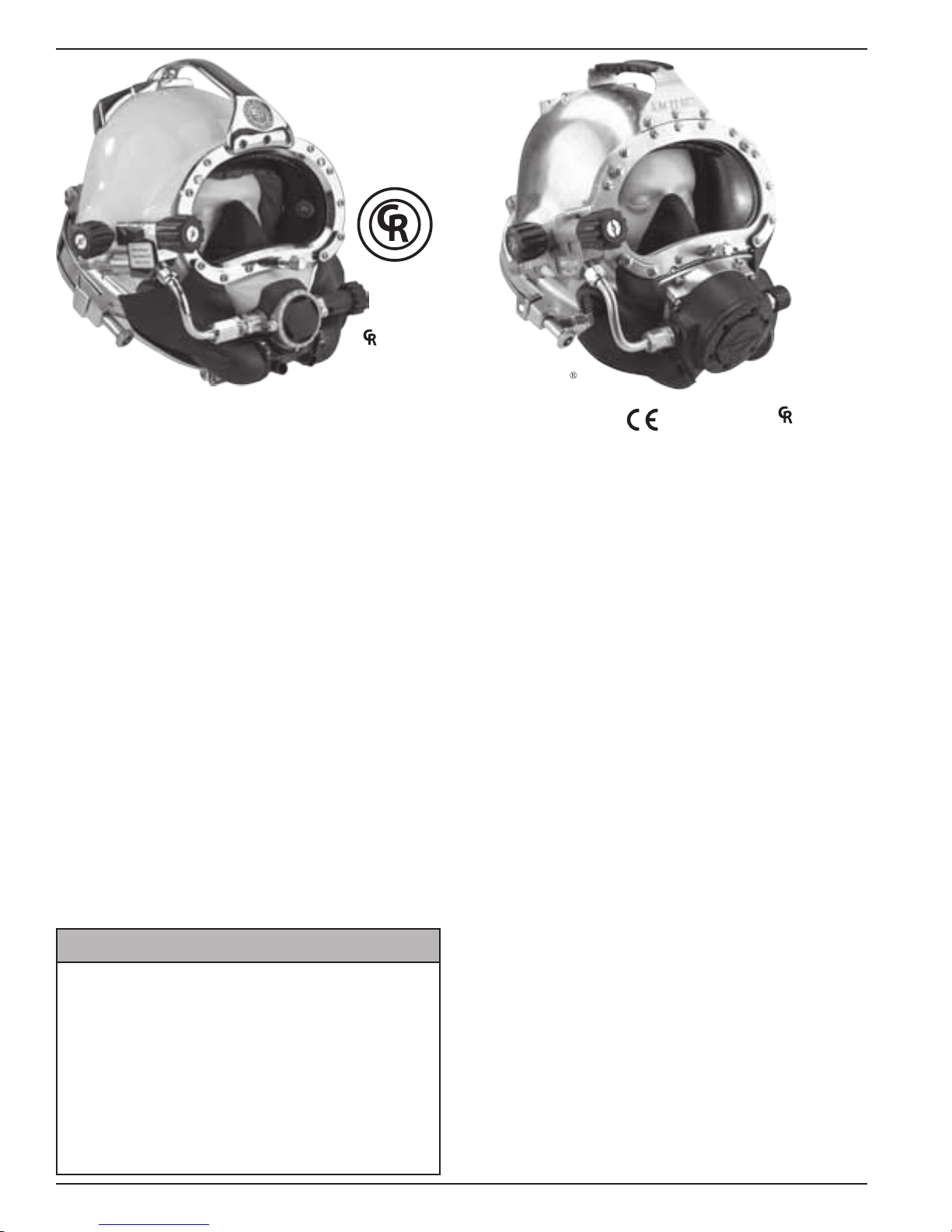
®
The Kirby Morgan® 57 helmet features our revolutionary new SuperFlow
®
450 Stainless Balanced
Regulator. It's machined from a stainless steel casting
for the ultimate in performance and reliability.
Like all KMDSI regulators on our helmets and
Band Masks
®
, we use only regulators that are specically designed for surface-supplied diving, that will
perform over the wide range of pressures delivered
by low pressure compressors. An ordinary SCUBA
regulator mounted on a diving helmet is not capable
of delivering the gas you need at heavy work loads.
This commercially rated fully diver adjustable regulator delivers all the breathing gas you might require
for the most demanding work underwater.
The Kirby Morgan
™
Valve
Exhaust System. It's recommended for div-
®
57 also includes our Quad
ing in biologically contaminated water, when you're
properly trained and equipped, using recommended
procedures. This new exhaust has exceptionally low
exhalation resistance that you must experience to
appreciate.
®
approved and ™ marked
The Kirby Morgan® 77 represents the rst in a new
generation of stainless steel diving helmets that provide an alternative for the diver who prefers a metal
helmet. The helmet features a stainless steel version
of our new REX
®
regulator, which offers the best
performance of any Kirby Morgan system.
It has the best work-of-breathing performance when
compared to ANY other commercial diving helmet.
The Kirby Morgan 77 Dive Helmet has been tested
and meets or exceeds European CE requirements and
is fully commercially rated.
The advantages of this all stainless steel helmet include the following:
• No renishing required if the surface is scratched
or gouged.
• Faster production of helmets for customer delivery.
B WARNING
Before attempting any diving in any
type of contaminated water, a complete diving and topside course in
hazardous materials emergencies
should be completed. The divers and
the topside team must be properly
trained and have the proper safety
equipment. All helmets and suits can
leak water under certain conditions.
Divers should use extreme caution
when diving in contaminated waters.
6 © ⅯⅯⅩⅡ Kirby Morgan Dive Systems, Inc. All rights reserved. Document #120614002
• Elim ination of th readed inserts for securing the port
retainer to the helmet shell.
• No need to remove the handle to remove the port
retainer.
• One piece sideblock includes both the free-ow valve
and the Emergency Gas System valve.
• The helmet ring is an integral part of the helmet.
Kirby Morgan® 47
®
approved and ™ marked
The Kirby Morgan
®
37SS features an all stainless
steel shell, as well as a stainless sideblock, helmet
ring, bent tube, handle, and other key components.
The SuperFlow
®
350 is standard on this helmet.
The K i rby Morgan 37SS featur es a quick change communications module, available with either bare wire
posts or a waterproof connector, and allows for easy,
efcient maintenance of the helmet's communications.
The advantages of this stainless steel helmet include
the following:
• Rugged helmet shell and other components
• No renishing required if the surface is scratched
or gouged
• Elimination of threaded inserts for securing port
retainer to helmet shell
© ⅯⅯⅩⅡ Kirby Morgan Dive Systems, Inc. All rights reserved. Document #120614002 7

Kirby Morgan® 47
WARNING
WARNING
CAUTION
CAUTION
Chapter 2
Description & Operational Specications
Kirby Morgan 47
This manual is our effort to explain the operation, maintenance and use of the Kirby Morgan helmet. We do not herein make any effort to teach the principles of diving. It is our
assumption the reader is a qualied diver. We highly recommend that all divers should
train, under controlled conditions, in the use of any model of commercial diving helmet
that they have not previously used or trained in, prior to use on the job, until they have
mastered the skills required to use their helmet correctly.
This section includes detailed descriptions of the
Kirby Morgan 47, as well as important operational
specications. With the exception of the regulators,
all parts are interchangeable.
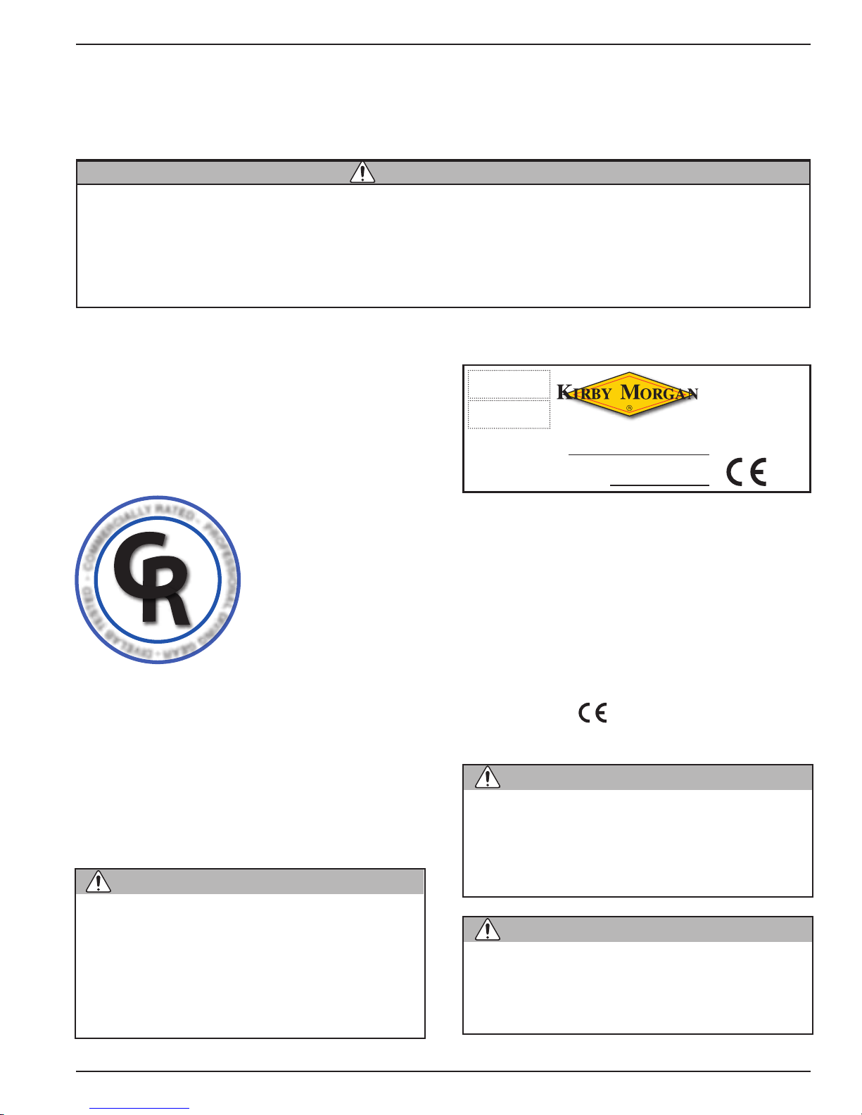
2.1 CR Marking
The helmet meets or exceeds all standards established
by Dive Lab of Panama City, Florida, and is CR
(Commercially Rated) marked.
A
R
T
Y
E
L
L
A
I
C
R
E
M
M
O
C
-
D
E
T
S
E
T
B
A
L
E
V
D
-
P
R
O
F
E
S
S
I
O
N
A
TM
L
D
I
V
I
N
G
G
E
A
I
R
D
-
TM
2.2 CE Certification
The helmet has been tested and conforms to the
performance requirements as set forth in Annex II of
Directive 89/686/EEC and, as far as applicable, the
EN 250:2000, EN 250/A1:2006 and EN 153331:2008 (class B). It is fully CE marked with demand
valve REX
Category of PPE: III
®
.
2.2.1. CE Marking
On the frame of the helmet the CE mark is afxed.
EN250:2000
EN250/A1:2006
EN15333-1:2008
CLASS B
HELMET MODEL:
YEAR OF PRODUCTION:
CE Mark
KIRBY MORGAN
DIVE SYSTEMS, INC.
1430 Jason Way,
Santa Maria, CA 93455
2049
In the mark the data reported are the following:
1. the name and the address of the manufacturer;
2. harmonized reference standard: EN 250:2000,
EN 250/A1:2006 and EN 15333-1;
3. Helmet model;
4. the serial number;
5. the year of production;
6. CE marking:
;
7. number of notied body.
The user cannot:
• remove the mark from the frame of the
helmet;
• modify or counter feit th e d a t a r e ported
on the mark.
The helmet has been tested with air and
CE certicates for use with air up to 50
meters. Compressed air must been compliant with the EN 12021.
All the tables reporting the technical data
and the pressure of use are relative to
compressed air.
© ⅯⅯⅩⅡ Kirby Morgan Dive Systems, Inc. All rights reserved. Document #120614002 9
The mark must be visible and legible
throughout the life of the PPE. If the mark
deteriorates or is not legible the user
should contact the manufacturer.
Kirby Morgan® 47
WARNING
WARNING
2.2.2. Notified Body
The Notifying Body is Eurons-Modulo Uno
S.p.A.
Address: Via Cuorgne,
21-10156 Torino,
ITALY
Identication number: 2049
2.3 Other Marking
The helmet Kirby Morgan 47 meets or exceeds all requirements of NPD, Health and Safety (U.K.), United
States Navy and ADCI United States.
2.4 Product Specifications
Weight: KM 47 - 30.96 pounds
Helmet Shell: Fiberglass, polyester resin, polyester
gel coat, and carbon bers
Regulator Body - Stainless steel
Control Knobs: ABS plastic
Lens: Clear polycarbonate
Neck Dam: Neoprene. Optional latex neck dam
available.
O-Rings: Buna-N
Head Cushion: Nylon bag lled with #4 Polyester
foam
Recommended Lubricants: Dow Corning
Silicone Lubricant. Krytox
also acceptable.
®
and Halocarbon® are
®
MS4
2.5.2 Minimum Operating Temperature
The KM-47 can be used in waters at water temperatures as low as 34 degrees Fahrenheit (1 degree
Celsius) without the use of a hot water shroud and
hot water to prevent freezing. However it is strongly
recommended that the hot water shroud be used for
the comfort of the diver. At the time of this writing a
specic part number hot water shroud is not available
for the KM-77 however work is underway to produce
one. The the standard shroud PN# 525-100 can be
modied to work. for more information contact Dive
Lab Inc. WWW.divelab.com
Without a hot water shroud, the diver may be subject
to hypothermia due to cold gas inspiration temperatures. Kirby Morgan makes no physiological recommendations regarding minimum safe operating
temperatures for divers using this helmet.
Diving in cold water, i.e., at temperatures
below 50 degrees F, may subject the diver
to severe respiratory heat loss. This may
lead to a decrease in body core temperature also known as “hypothermia.”
Hypothermia is extremely dangerous and
can lead to a loss of reasoning ability, decreased manual dexterity, uncontrollable
shivering, unconsciousness, and death.
Never use aerosol-propelled sprays near
the face port of any Kirby Morgan diving helmet. The propellant used in these
aerosols can invisibly damage the face
port and cause it to shatter on impact
from any strong blow. If the face port fails
underwater, injury or death may result.
If you have any questions regarding proper set-up,
operation, or maintenance of your Kirby Morgan
helmet contact KMDSI (805) 928-7772 or at kmdsi@
KirbyMorgan.com or Dive Lab Inc. (850) 235-2715
or at Divelab@aol.com. There are also detailed
checklists for the set-up and maintenance of your
helmet on the Dive Lab web site at www.divelab.com.
2.5 Regulator Performance
2. 5 .1 REX® Regulator
The REX
high performance. The regulator has been tested at
Dive Lab at Panama City, Florida. It meets or exceeds
all current U.S. Navy and European diving standards.
®
regulator on the Kirby Morgan 47 offers
2.6 Cage Code
The cage code for identifying KMDSI products for
U.S. government purposes is 58366.
2.7 Operational Specifications &
Limitations
-Umbilical minimum I.D. 3/8” (9.5 mm) of not more
than two sections, total length not to exceed 600 feet
(183m).
Recommended over-bottom (OB)gas supply pressure
for best performance at depths are calculated by the
formula (fsw x 0.445+14.7) + recommended p.s.i g.
The calculations for specic depths are shown in the
Appendix.
The umbilical assembly should be composed of good
quality diving hose that meets industry standards.
Generally, gas hose will be married to the communications wire, pneumofathometer hose, and strength
member in a manner that will allow the strength
member to receive all the strain. There are also good
quality umbilicals available that are assembled at
10 © ⅯⅯⅩⅡ Kirby Morgan Dive Systems, Inc. All rights reserved. Document #120614002
the factory using a twisted method which does not
WARNING
DANGER
WARNING
WARNING
WARNING
require marrying. Regardless of the system used, the
umbilical is the diver’s life line and should always be
of excellent quality and maintained carefully.
The demand regulator and
side block assemblies have
a maximum design pressure
of 225 p.s.i.g. (15.5 bar) overbottom. Higher pressures
could lead to component
failure and serious personal
injury.
Decompression diving always involves
the risk of decompression sickness.
Omitted decompression due to a loss of
the breathing gas supply or other accidents can cause serious injury or death.
Use of a Kirby Morgan helmet or mask
cannot prevent this type of injury.
It is important for the user/diver to take
excessive currents into consideration.
The exhaust system on the REX
®
Regulator will help prevent water intrusion
when diving in heavy currents. The REX
®
exhaust system does not limit the diving
depth.
Gas systems used to supply Kirby Morgan helmets and masks must be capable
of supplying gas to the diver at the required pressure and ow rates as stated
in the operational specications. The use
of unregulated gas sources is extremely
dangerous.
The use of standard SCUBA type regulators is unacceptable, as there are no
provisions for adjusting the intermediate
pressure to the diver. Only proven systems that allow for varying the gas supply
pressure to the diver should be used for
umbilical diving.
Kirby Morgan® 47
When the helmet is used
for air diving in countries
that conform to C.E. regulations it must be used to a
maximum depth of 164fsw
(50msw). I.A.W. EN 15333-1.
If you have any questions regarding proper set-up, operation, or maintenance of your Kirby Morgan helmet contact
KMDSI (805) 928-7772 or at kmdsi@KirbyMorgan.com
or Dive Lab Inc. (850) 235-2715 or at Divelab@aol.com
2.8 Helmet Features
All Kirby Morgan diving helmets are manufactured
by hand. Each step of the manufacturing process is
carefully controlled to assure the customer a high
quality, durable helmet that will function properly.
The KM 47 was initially developed in 2005. The
goal was to bring together all of the top design elements of the various Kirby Morgan helmets and then
rene the mix into what we at KMDSI consider to be
among the best in current diving helmet design. The
KM 47 takes the proven design features of our world
famous SuperLite
advanced design features of the SuperLite
some balance renements, and our REX
and you have a superb diving helmet. Exemplifying our adherence to the highest quality and proven
superior work performance, the KM 47 is another
outstanding helmet from Kirby Morgan.
The KM 47 incorporates the innovative locking system and communications system of the SuperLite
27 onto a larger SuperLite
The 47 features the REX
tor which provides superb breathing gas ow during
peak work output.
The helmet consists of two pieces: the helmet shell/
helmet ring and the neck dam/neck ring assembly.
The machined helmet ring houses the sealed pull
pins and locking collar, and provides protection for
the bottom end of the helmet. The adjustable neck
pad on the locking collar, in combination with the
internal chin strap and adjustable head cushion, gives
the diver a secure, custom tailored t in the helmet.
The superior t and balance makes the helmet sit
comfortably for long periods of time even when
working in the face down position.
A quick change communications module, available
in either bare wire posts or a waterproof connector,
®
17 A/B and blends in many of the
®
17 size berglass shell.
®
adjustable demand regula-
®
27. Add in
®
regulator,
®
© ⅯⅯⅩⅡ Kirby Morgan Dive Systems, Inc. All rights reserved. Document #120614002 11
Kirby Morgan® 47
WARNING
allows for easy, efcient maintenance of the communications in the helmet.
Before attempting any diving
in any type of contaminated
water, a complete diving and
topside course in hazardous materials emergencies
should be completed. The divers and the
topside team must be properly trained
and have the proper safety equipment.
All helmets and suits can leak water
under certain conditions. Divers should
use extreme caution when diving in contaminated waters.
The KM 47 has the REX
®-3®
exhaust system, which
is recommended for diving in contaminated water.
Other helmet features which are common to most
KMDSI helmets include:
• the face port and retainer ring
• communications components
• the oral/nasal mask
• the nose block device
• the air train
• the side block, emergency valve,
and non-return valve
Many of the breathing system components on these
helmets are also compatible with the KMB 18B and
28B full-face masks and the EXO-26. This helps reduce the inventory of spare parts that must be carried
by commercial diving companies.
Each step of the manufacturing process is carefully
controlled to assure the customer of a high quality,
durable helmet that will function properly. The following is a general description of the features of the
KM 47.
1) The face port (or view port) area remains unchanged from the SuperLite
®
-17B. The side block
is also the same. Many of the components in these
sub-assemblies are interchangeable between the 17B
and the KM 47.
2) The bottom of the KM 47 berglass helmet mates
with the helmet ring that is installed at the factory.
This metal ring receives the neck dam ring which
seals to the helmet with an O-ring. The seal is very
air/water tight. The metal bottom of the KM 47 is
quite durable in normal use, but care should be taken
not to drag the helmet bottom on the deck.
3) The neck dam on the KM 47 is sandwiched between the neck dam rings, securely holding it in place.
Replacement neck dams install easily. Latex or foam
neoprene neck dams are available.
4) When the neck dam/neck ring is locked into place
on the helmet, it is located up inside the protective
helmet ring (that the neck ring O-ring seals to) which
protects the neck ring and neck dam from side impact
damage during the dive.
5) The neck dam design (latex or neoprene foam)
helps position the helmet correctly. Replacement neck
dams should only be genuine KMDSI/Kirby Morgan
neck dams to assure proper operation and comfort.
An internal adjustable chin strap helps to secure the
diver’s head in the helmet.
6) A new locking collar design holds the neck ring
in the sealed position. The O-ring seal is continuous
once the neck ring enters the helmet ring.
7) Attached to the locking collar is an adjustable
neck pad that should be adjusted to the diver prior
to diving. This will improve the t and performance
of the KM 47.
8) A system of two sealed pull pin locks is on the KM
47. One lock is located on each side of the helmet.
The spring and sliding shaft of these locks are inside
an O-ring sealed main body. The interior of the main
body is lled with silicone uid. No ne sand or other
debris can reach the interior of these locks to interfere
with their operation.
9) The head cushion attaches just inside the bottom
of the helmet, keeping it in place when the diver
dons the hat. The standard head cushion consists of
a brushed nylon bag with an open cell polyester foam
inside. The 17B head cushion should not be used in
the KM 47 because the design of the head cushions
is different. Only genuine Kirby Morgan KM 47 head
cushions should be used to assure proper operation
and comfort.
10) The handle that is tted to the top of the helmet
and the port weight are areas that can be used as
mounting brackets for lights, TV cameras, etc.
11) The communications system is a modular, quick
change design.
12) The exhaust system is a three valve design, the
®
REX
-3, that helps to keep the helmet exceptionally
dry.
12 © ⅯⅯⅩⅡ Kirby Morgan Dive Systems, Inc. All rights reserved. Document #120614002
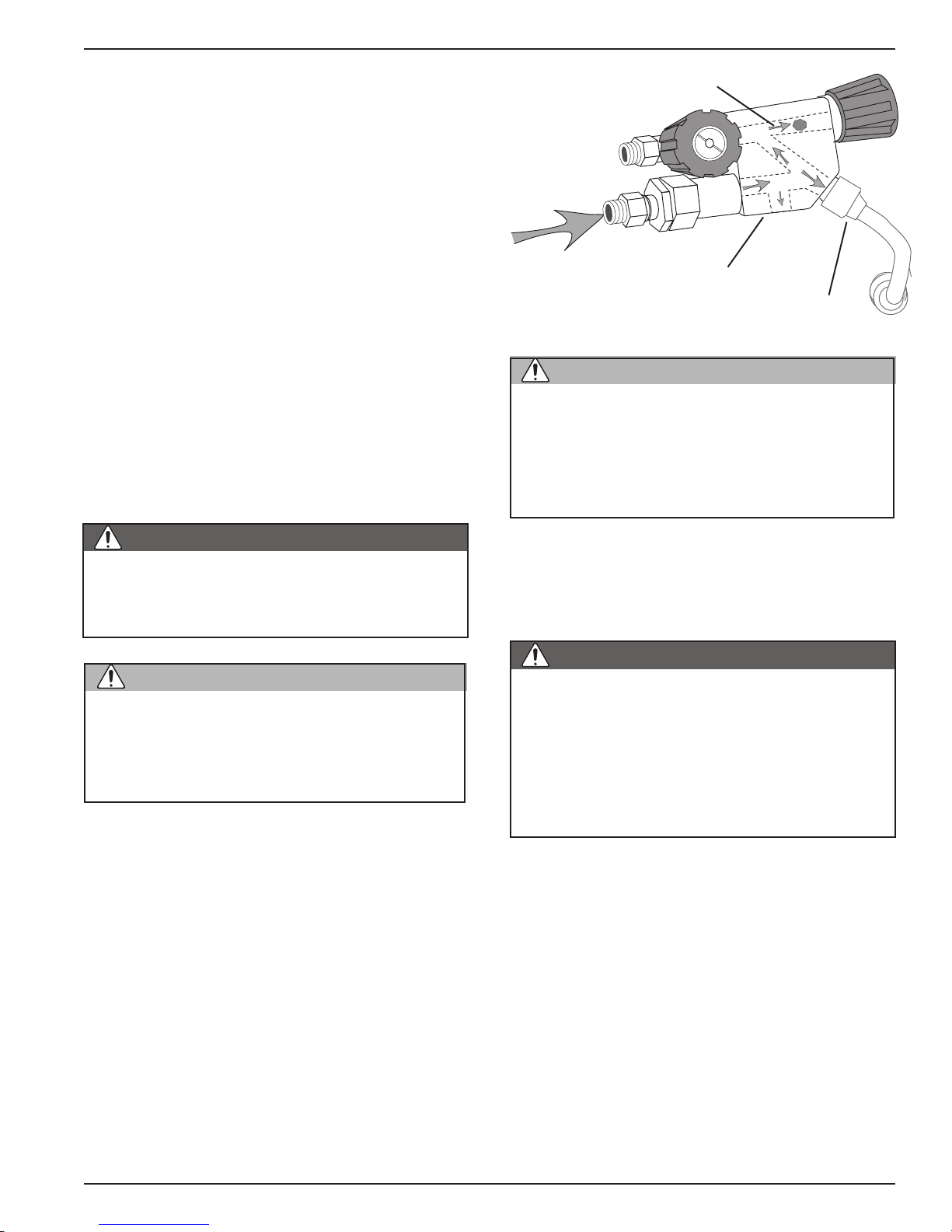
Kirby Morgan® 47
DANGER
CAUTION
WARNING
DANGER
2.9 General Description
2.9.1 Helmet Shell
The helmet shell is fabricated of noncorrosive, rigid
berglass which will not carry an electrical charge.
This shell is the central structure for mounting all the
components that make up the complete helmet. It is
designed to allow easy replacement of parts when
necessary. Any repair to the helmet shell must be
done at an approved KMDSI repair center.
On the Kirby Morgan helmets, the helmet ring is attached to the base of the helmet shell at the KMDSI
factory. This chromed brass helmet ring must not
be removed by anyone other than the factory or a
KMDSI approved repair center.
2.9.2 Gas Flow Systems
The main gas supply ow from the umbilical enters
the system at the adapter and ows through the one
way valve to the interior of the side block. The one
way valve or “non-return” is a very important component.
Gas Flow To Air Train
EGS
Gas Supply
Main Gas
Supply
Auxiliary L.P. Port
Gas Flow
To Regulator
The one way valve must be tested daily,
prior to the commencement of diving operations. Failure of one way valve could
cause serious injury or death. Follow the
procedures for testing the valve in this
manual.
Never attempt to remove or service the
chromed ring on the base of the helmet
shell. Improper servicing of this ring can
lead to helmet ooding and death.
The bent tube assembly for the KM47 is
a unique design and is not interchangeable with the bent tube assembly used
on other Kirby Morgan masks and helmets.
The one way valve prevents the ow of gas out of
the helmet to the umbilical in the event of a sudden
lowering of pressure in the umbilical. This can happen
due to an accidental break in the hose or a tting near
the surface. Not only would the emergency gas be lost
if the one way valve failed (concurrent with a hose or
tting break on deck), but the diver could suffer from
a serious “squeeze” that could cause injury or death.
Although we have selected the valve for its reliability and quality, inspection and maintenance of
this valve must be done regularly. It is very easy to
disassemble and inspect. (A rebuild kit for this valve
is Part #525-330).
The emergency gas comes from a tank of compressed
gas worn by the diver. It enters the system through
the Emergency Gas valve when the diver turns the
control knob on. The ow then enters the side block.
Never connect the main gas supply
hose from the diving station/umbilical
to the auxiliary valve. There is no one
way valve in the emergency gas valve.
If this mistake is made, any break in the
supply hose could possibly result in a
“squeeze”. This could result in serious
injury or death.
Both sources of gas ow through the same passage in
the side block body to three exits. One exit is always
open to supply gas to the demand regulator assembly.
The second exit is to the defogger valve (also known
as the free-ow or steady-ow valve) assembly. The
third is to the port on the side block to connect a dry
suit inator hose.
The diver controls the ow of gas through the defogger system with the control knob. The gas enters the
helmet and ows through the air train which directs
the gas onto the face port to help eliminate or clear
fogging that forms on the port from the diver’s warm
breath.
© ⅯⅯⅩⅡ Kirby Morgan Dive Systems, Inc. All rights reserved. Document #120614002 13
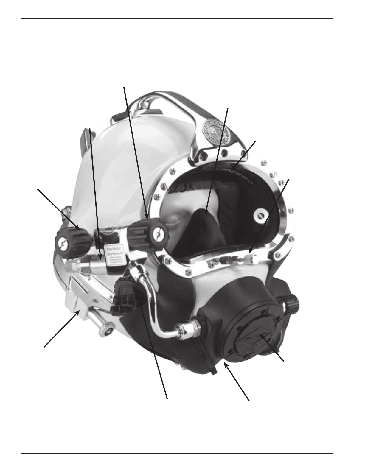
Kirby Morgan® 47
FEATURES OF THE KM 47
Gas Supply Non-Return
Valve prevents loss of gas pressure
in the event of umbilical damage,
preventing a “squeeze”.
Emergency Gas Supply
Valve provides the emergen-
cy breathing gas to the diver.
Steady Flow Valve provides an ad-
ditional ow of air into the helmet for
ventilation and defogging. The air/gas
ow is through the air train, across the
faceplate into the oral nasal mask.
Silicone Oral Nasal Mask is made of
a superior silicone material which is hypoallergenic and has a longer work life than
latex.
Air Train
breathing air/gas onto the face plate
to defog the lens.
diffuses the incoming
Nose Block Device
allows the diver to
block the nose to equalize the ears.
Positive-Lock® Latch System
The latch catches consist of two spring
loaded sealed pull pins which are pulled
forward to release the locking collar and
neck dam system. Even when the latches
are released, the neck dam maintains a
positive seal and will not allow the seal
to be broken until the locking collar
actually clears the diver’s shoulders.
14 © ⅯⅯⅩⅡ Kirby Morgan Dive Systems, Inc. All rights reserved. Document #120614002
Modular Communications System
can be either bare wire posts as shown or a
waterproof connector. The waterproof type
is recommended when a “round robin” or
diver/tender both mics “on” communications
system is used.
REX® Regulator
has exceptional
breathing characteristics and an
extremely low
work-of-breathing.
Neck Dam Swing Catch
The Swing Catch rotates out of
the way to allow the neck dam
assembly to be unsealed from the
helmet. This simplies getting out
of the helmet.
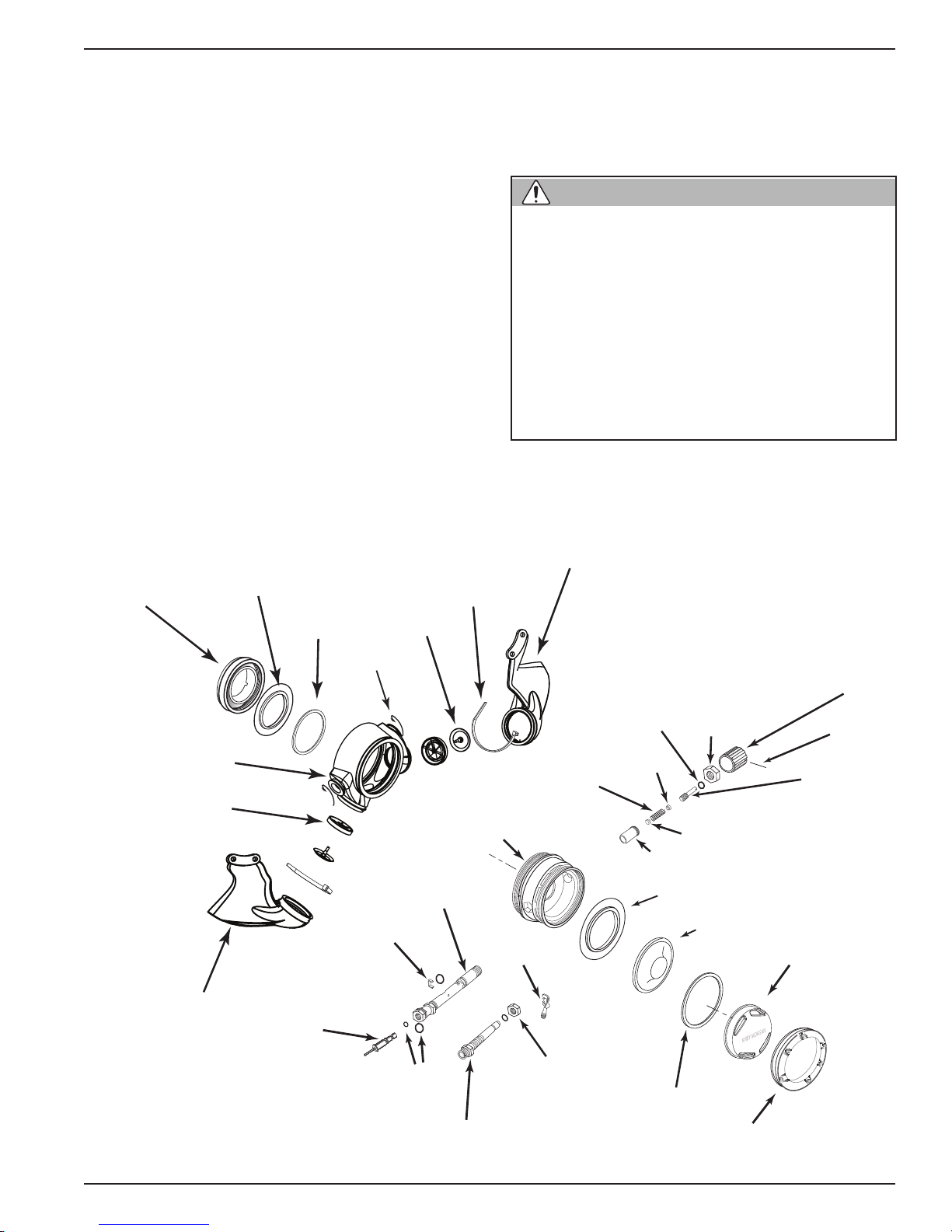
Kirby Morgan® 47
WARNING
The gas ow continues out through the regulator
exhaust system, or into the oral nasal mask by means
of the oral/nasal valve. The diver can breathe from
this ow of gas if the demand regulator malfunctions. The gas then ows into the regulator and out
through the regulator exhaust. From there it can exit
through either of the exhaust valves and out through
the whiskers.
Returning to the side block assembly: the other passage for gas is to the demand regulator. It goes to a
bent tube assembly that connects to the inlet nipple of
the demand regulator. The ow of gas in the demand
regulator assembly is controlled by the inlet valve
that supplies gas to the diver on inhalation “demand”
only, and shuts off during the exhalation cycle.
The side block on the helmet is drilled and tapped
to accept low-pressure inator hoses. This allows
the diver the capability to inate variable volume
dry suits. It is tapped with a 3/8-24 thread orice,
standard for American rst stage SCUBA regulator’s
low-pressure auxiliary ttings. The port is shipped
plugged at delivery. This ination capability does not
signicantly interfere in any way with the breathing
characteristics of the regulator during normal use
providing a limiting hose is used. The dry suit ination hose should be one that is restricted to ow less
than 100 LPM.
The side block inator port is intended
for dry suits only. When using the side
block low-pressure inflator port, only
good quality hoses and ttings should be
used and must incorporate an in-line ow
restrictor to reduce gas ow in the event
of hose failure. Any hose or tting failure
in this arrangement will subject the diver
to a decreased air supply. Do not use the
side block inator port for any purpose
other than attaching a dry suit hose.
Regulator
Mount Nut
Starboard Whisker
Exhaust
Main Body
Valve Seat
Water Dump
valve
Inlet valve
Thrust
Washer
Horseshoe
Tie Wrap
Main tube
Exhaust
Valve
Tie Wrap
Regulator body
Roller lever
Port Whisker
Spring
O-ring
Spacer
Sleeve
Exhaust valve
Nut
Spacer
Diaphragm
Knob
Roll pin
Adjustment
shaft
Cover
Exploded view of the REX® regulator.
© ⅯⅯⅩⅡ Kirby Morgan Dive Systems, Inc. All rights reserved. Document #120614002 15
O-ring
Nipple tube
Adjustment
lock nut
Washer
Cover
Retaining Ring
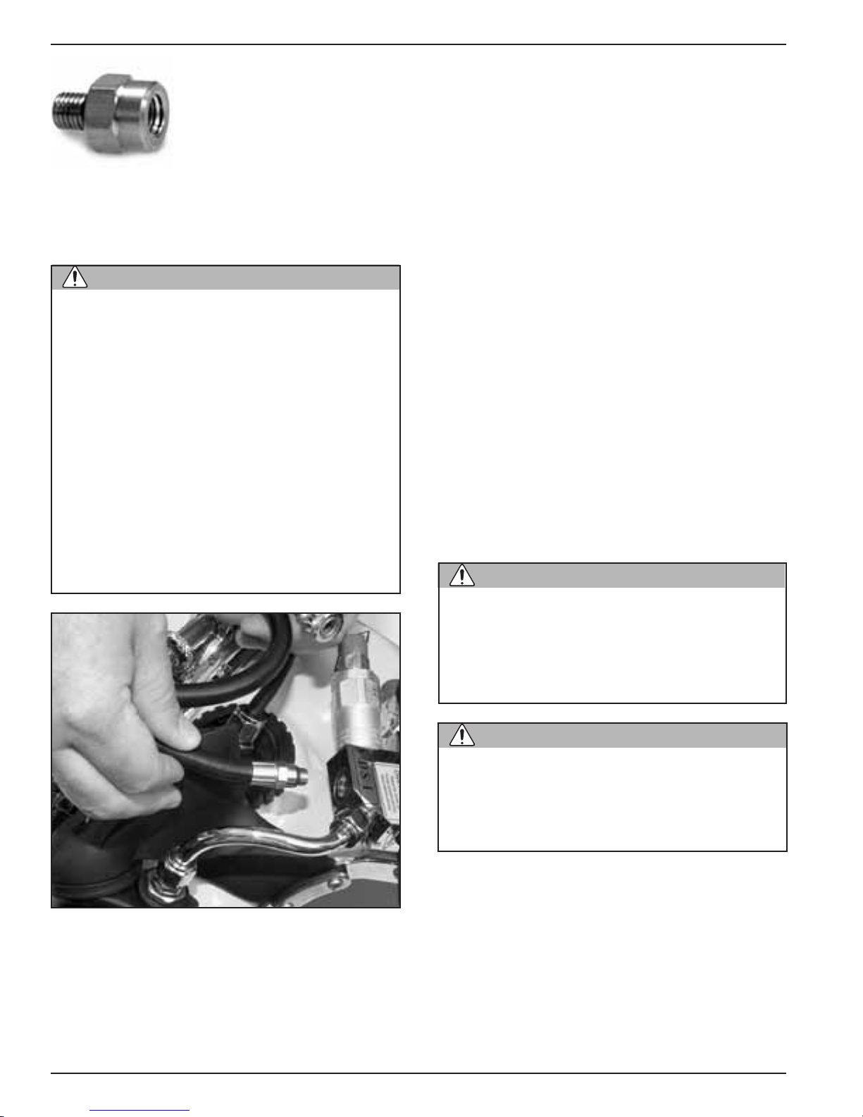
Kirby Morgan® 47
WARNING
CAUTION
CAUTION
The KMDSI Restrictor Adaptor,
KMDSI Part #555-210.
ebbs and stops. When the diver exhales, the supply
gas stays off as the exhalation gas ows through
the regulator body, out the regulator exhaust valve,
through the whisker, and out into the water. The
whiskers deect the exhaust bubbles away from the
face port to keep the diver’s view clear.
Otherwise, the hose should be equipped with a ow
restrictor (P/N 555-210) to limit ow in the event the
hose ruptures or is severed.
When using the side block low pressure
inator port, the diver should only use
high quality hoses with an integrated ow
restrictor or a KMDSI ow restrictor PN#
555-210. All hoses must have an in-line
restrictor to reduce the gas ow in the
event of hose failure.
Do not use tting adapters. Standard
adapters do not provide an adequate ow
restriction. The use of many off-the- shelf
adapters on the side block assembly
could expose the low pressure hose ttings to excessive stress. Any failure of
an ination hose will subject the diver to
a decreased supply pressure.
All KMDSI Helmets and Band Masks are equipped
with a multi-turn demand regulator adjustment knob.
This adjustment knob allows the diver to make corrections to compensate for a wide range of incoming
gas supply pressures.
The adjustment knob operates by simply increasing
or decreasing the amount of spring bias tension on the
demand regulator inlet valve. The adjustment knob
has a range of approximately 13 turns from full in
to full out. The intent of this bias adjustment device
is strictly to allow the diver to make adjustments for
variations in umbilical supply pressure.
This adjustment device is not intended as a minimummaximum device. Minimum and maximum applies
to supply pressure only. The adjustment knob should
be adjusted by the diver to be at the easiest breathing setting at all times. The exact number of turns
required is dependent on the supply pressure.
Low pressure hoses may be connected to the side
block.
®
The REX
divers inhalation and opens the inlet valve, matching
the diver’s need. The regulator continues to match the
diver’s inhalation as the rate increases, peaks, then
demand regulator senses the start of the
Diving a KMDSI helmet or band mask
with a bias setting greater than that just
necessary to keep the demand valve
from free owing increases the work of
breathing and reduces the diver’s ability
to perform heavy work.
The regulator adjustment knob should be
adjusted to the easiest breathing setting
at all times. Adjusting the regulator further in than necessary to keep from freeowing increases breathing resistance.
2.9.3 Emergency Gas Supply System (EGS)
KMDSI strongly recommends that the working diver
carry an independent supply of compressed gas (or
air) tted with a rst stage regulator and hose that is
connected to the inlet of the Emergency Gas Supply
Valve (EGS).
The KMDSI Overpressure Relief Valve, (part number
200-017) is fully adjustable and rebuildable and has
been designed to relieve any over-pressurization of
16 © ⅯⅯⅩⅡ Kirby Morgan Dive Systems, Inc. All rights reserved. Document #120614002
 Loading...