

Kirby Morgan 37 User Manual
Kirby Morgan 37 & 57
CAUTION
Breathing System Maintenance and Repairs
Chapter 7.0
7.1 Introduction
This chapter covers the maintenance and repair of all
components of the breathing system. The breathing
system includes the one way valve, the emergency
valve, the side block, the bent tube assembly, the
demand regulator, and the oral/nasal mask.
The breathing systems on all Kirby Morgan helmets
and masks are simple and highly reliable. The fact that
they can continue to operate when the components are
not in a well-maintained condition can cause divers
to become complacent about maintenance.
Your life depends on the correct function of this
equipment!
While Kirby Morgan helmets and masks are simple
to maintain, like any type of life support equipment,
they do require regular periodic maintena nce to f unction properly.
All parts disassembled should be thoroughly cleaned
using the methods described in the Appendix in the
rear of this manual. Components that require the use
of lubricants, sealing and thread locking compounds
should also be maintained.
Most fasteners have a torque value, it is imperative that
all fasteners which have a torque value be tightened
to the torque specifications as outlined by the procedure, or as listed in appendix 1. If in doubt as to the
proper torque setting, contact your local authorized
repair facility or KMDSI.
7.2 One Way Valve
NOTE: The one-way valve assembly should be disassembled, cleaned and the three O-rings should be
replaced at least annually. Damaged and/or corroded
parts should be replaced. A repair kit is available for
replacement parts (525-330).
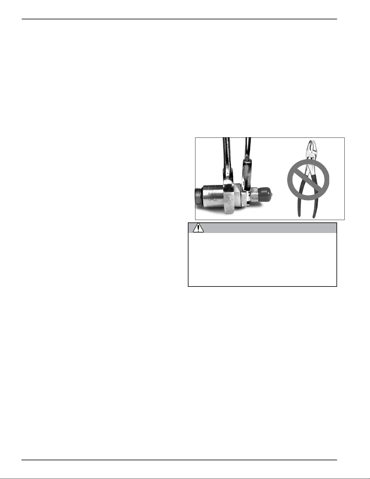
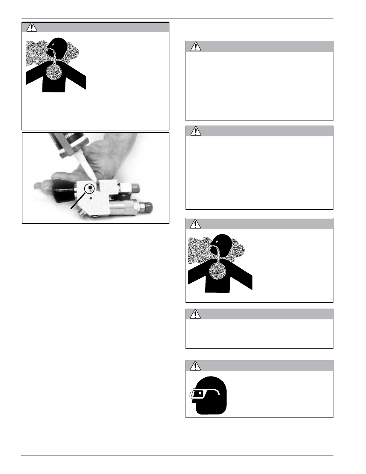
Use two wrenches or hold the hex part
of the body in a vise while removing or
turning the seat with a wrench. Do not
use pliers on the main body of the oneway valve. You may damage the valve if
pliers are used.
7.2.1 Disassembly Of The One Way Valve
Tools Required:
Soft Jaw Vice
1 inch Open End Wrench Attachment on Torque
Wrench
(If no vise is available use a backup 1 inch open end
wrench)
68
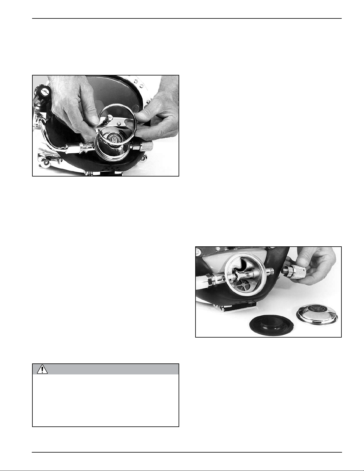
To disassemble and inspect the one way valve assembly:
1) The one way valve assembly must be removed
from the side block. Use the open end wrench to
remove it.
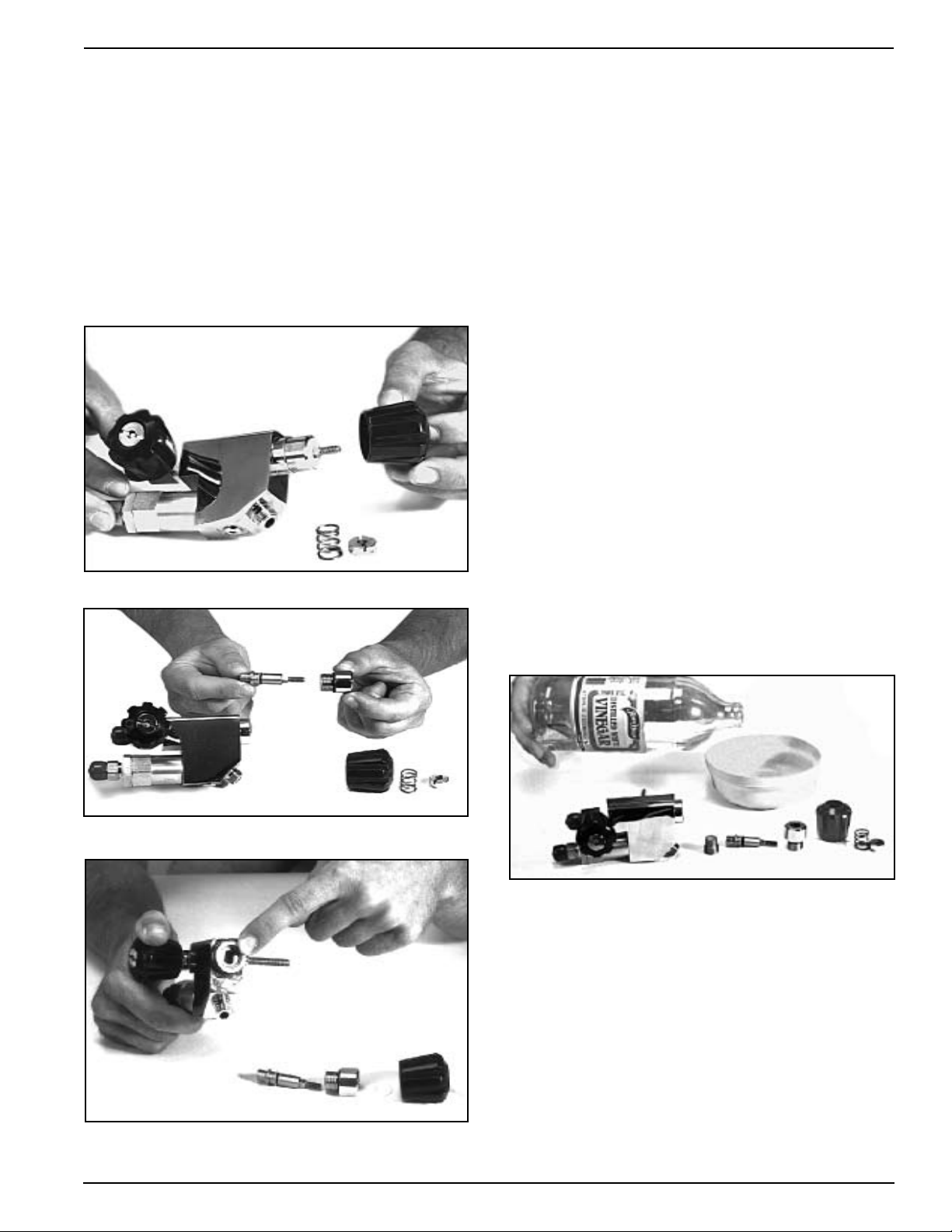
2) After the one way valve has been removed, use two
wrenches or hold the hex part of the body in a soft jaw
vise while removing the seat with a wrench.
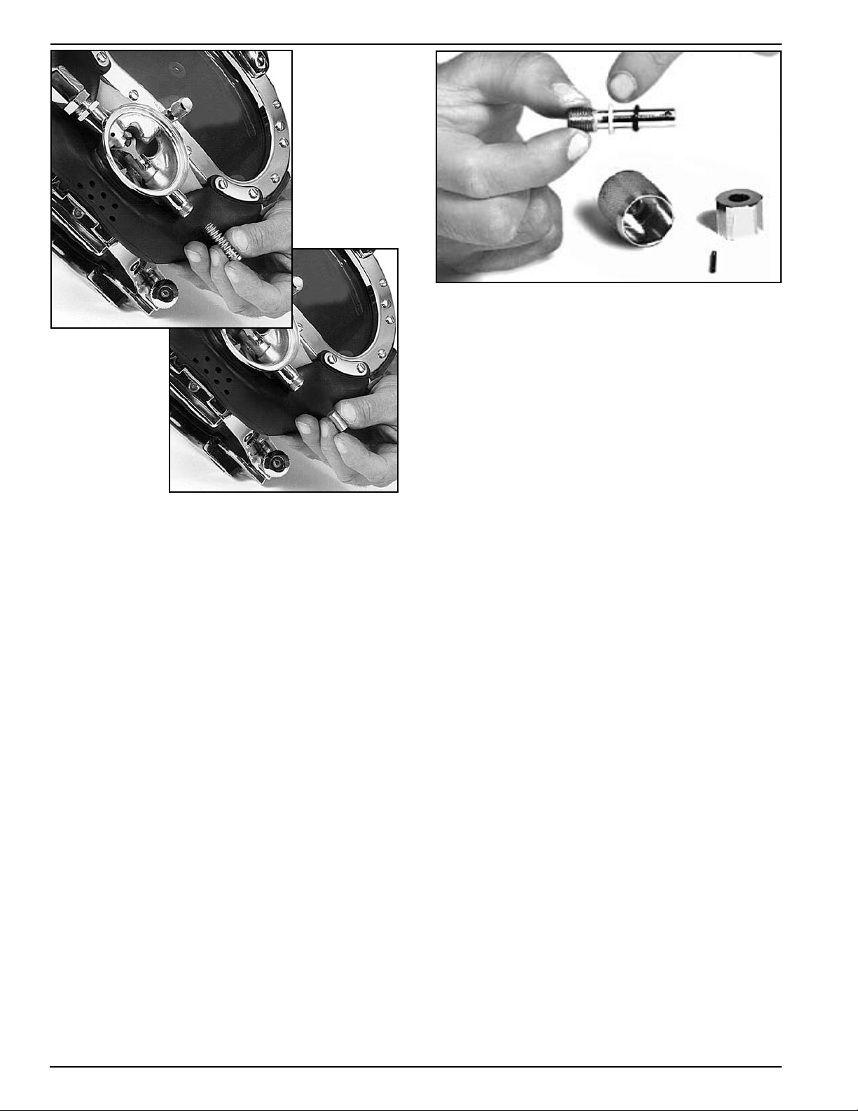
As the seat is removed, the wiper and the O-ring
will slide out in place in a groove on the seat. The
© Copyright 1970-2008 Kirby Morgan Dive Systems, Inc. All rights reserved. Document # 080508001
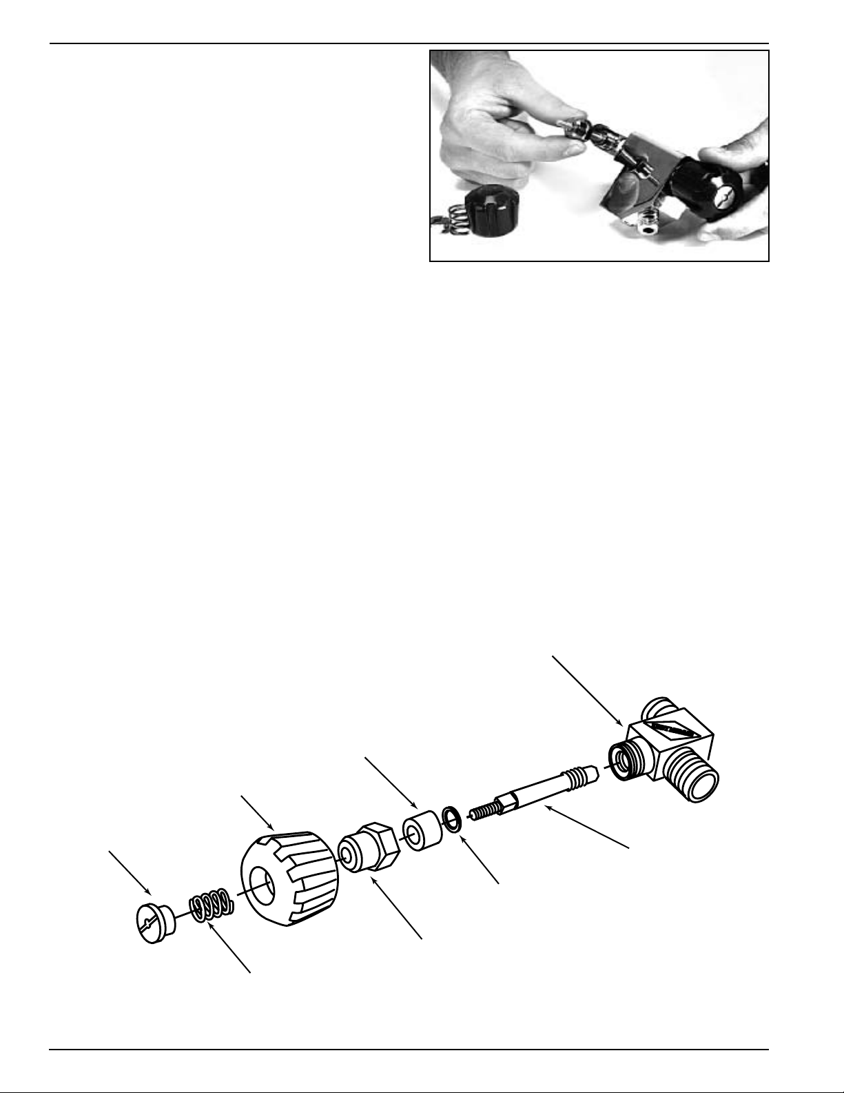
WARNING
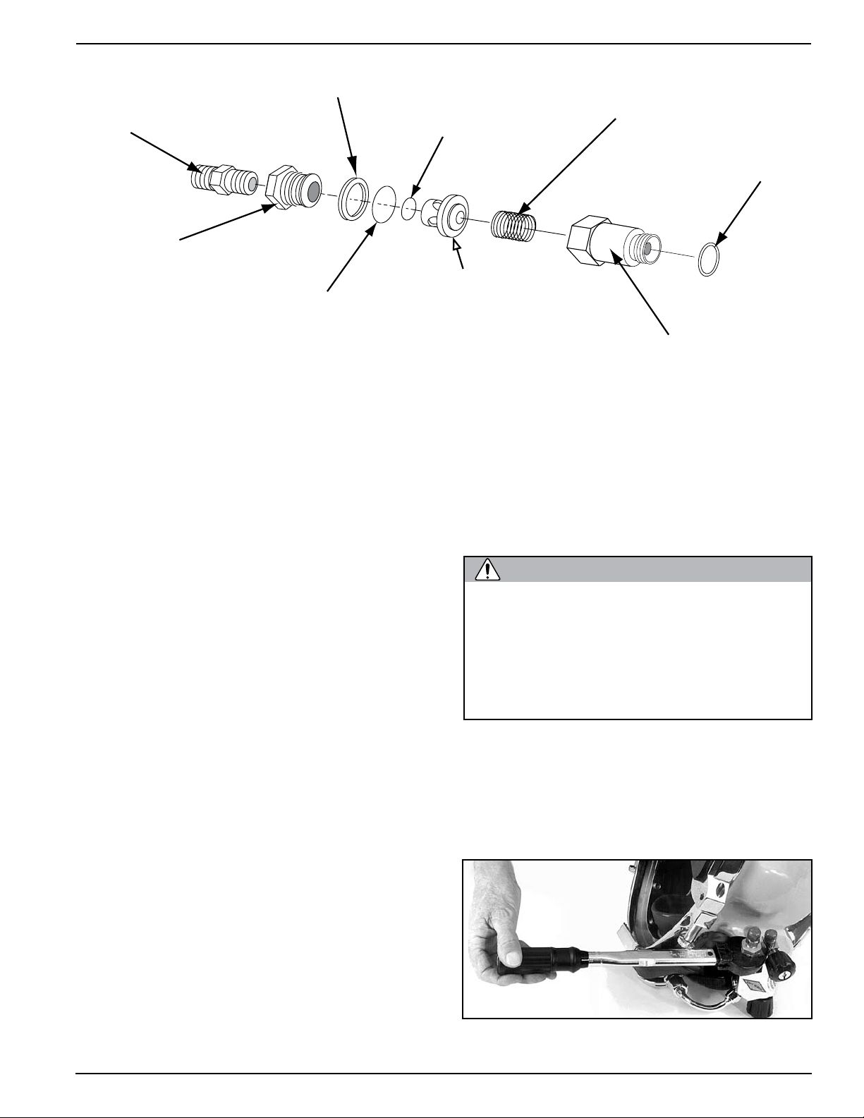
Correct assembly order of the one way valve.
Adapter
Seat
Wiper
O-ring
O-ring
Poppet
Spring
Body
O-ring
Kirby Morgan 37 & 57
poppet and the poppet O-ring usually come out in
the seat being followed by the spring.
The only functional part remaining in the valve body
is a non-moving, pressed-in cage. The function of the
cage is to prevent the poppet O-ring from blowing out
of place during high flows. Do not remove the pressed
in cage. This can only be done at the factory.
3) Inspect the body interior for foreign matter of any
type and clean, if necessary. Clean in accordance with
the cleaning instructions in Chapter 6. If corrosion is
present, clean using the acidic solution as outlined
in Chapter 6.
4) Inspect the seat, wiper, O-ring, poppet O-ring and
poppet for wear, replace if necessary. Be sure each
part is clean and all components are lightly lubricated
with the appropriate lubricant. A repair kit is available
for replacement parts. (Part #525-330)
5) Be careful to wipe the poppet and poppet O-ring
thoroughly, removing nearly all silicone to prevent
foreign materials from sticking to these components.
6) Replace the spring.
seat. Thread the seat into the valve body.
4) Tighten the seat to 150 inch lbs. (17 Newton meters) with a torque wrench while holding the body
in a soft jaw vice or wrench.
5) If the adapter has been removed, it must be cleaned
and wrapped with Teflon tape.
Do not allow any Teflon tape to cover the
end of the adapter, or to enter the oneway valve. Loose pieces of Teflon tape
can interfere with the performance of the
one-way valve or the regulator and may
block the diver’s air supply. This could
lead to death through suffocation.
6) Test the operation of the valve.
7) Place the new O-ring on the end of the one way
valve assembly and reinstall the valve assembly in
the side block. Tighten to 150 inch lbs. (270 kg.cm.)
with a torque wrench.
7.2.2 Reassembly of the One Way Valve
1) Slide the new O-ring over the poppet.
2) Insert the new spring into the valve body, followed
by the poppet.
3) Next, install the new O-ring and new wiper on the
© Copyright 1970-2008 Kirby Morgan Dive Systems, Inc. All rights reserved. Document # 080508001
Tighten to 150 inch lbs. (17 Newton Meters) with a
torque wrench.
69
Kirby Morgan 37 & 57
7.3 Side Block Assembly
7.3.1 General
The side block should be overhauled at least annually,
or whenever components show signs of wear, damage
or do not function smoothly or properly. Minimum
replacement components during overhaul includes
all O-rings. A repair kit is available for replacement
parts (Part #525-311).
The side block does not require removal from the
helmet each time an overhaul is being conducted
providing inspection of the internal passages does not
reveal contamination or excessive corrosion. However, the side block should be completely removed at
least every three years of active use to ensure fasteners
are not corroded or frozen.
The side block assembly is held in place on the helmet
shell by a stud, flat washer, lock washer, nut, and a
mach ine screw. T he screw does some securing but its
main function is to prevent rotation of the side block.
The stud also extends into the interior of the helmet
shell far enough to secure the air train by means of
the washer and nut.
The air train cup that fits over the stud is made of
soft brass and cannot be used for a bearing surface to
mount the side block. RTV silicone rubber compound
is used to form a gas tight seal between the side block
and the exterior of the helmet shell.
7.3.2 Side Block Assembly Removal
Tools Required:
7/16,11/16, and 7/8 inch Open End Wrenches
11/16 and 7/8 inch Open End Wrench Attachment on
Torque Wrench
1/4 inch Flat Blade Stubby Screwdriver
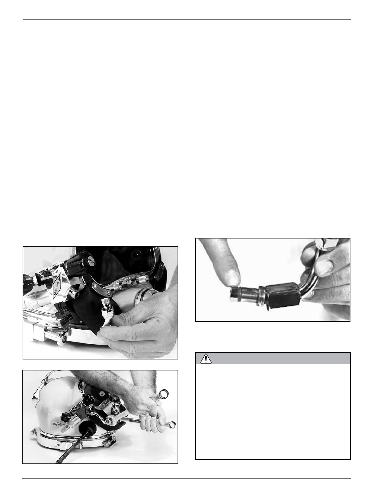
Loosening the bent tube from the side block.
7.3.3 Separating the Side Block Assembly
from the Helmet Shell
Tools Required:
Putty Knife
7/16 inch Open End Wrench
1/4 inch Flat Blade Stubby Screwdriver
1) Removal of the side block assembly requires removing the air train.
2) Remove the nut and washer that secure the air train,
then the air train itself.
3) The st ud nut is remove d next, with the lock washer
and flat washer.
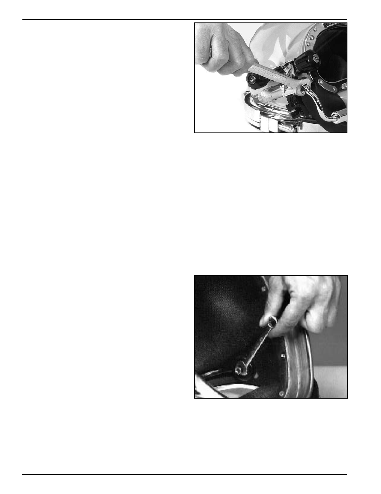
The bent tube assembly must be ent irely removed before removal of the side block assembly is started.
1) Completely unscrew the bent tube assembly nut
(14) from the side block.
2) Using two wrenches, hold the nut at the regulator
end of the bent tube assembly with the first wrench.
With the other wrench, loosen the jam nut (100) by
turning the wrench DOWN.
3) Unscrew the bent tube nut until it comes free, then
pull the bent tube assembly straight out of the regulator inlet nipple.
4) The side block assembly is ready to be separated
from the helmet shell at this time.
70
© Copyright 1970-2008 Kirby Morgan Dive Systems, Inc. All rights reserved. Document # 080508001
Loosening the nut that holds the air train.
4) Next, the alignment screw is removed.
NOTE: The alignment screw is located in a recess in
the fiberglass next to the stud. This recess is normally
filled with RTV. The RTV must be scraped free to reveal
the screw.
Knob
Spring
Washer
Locknut
Bonnet
Valve stem
O-ring
Washer
Side block
Stud
Bent tube
Seat
Plug
O-ring
O-ring
O-ring
O-ring
Air Train
Air Train
Gasket
A thin putty knife helps to remove the side block.
5) The side block assembly is now unfastened, but
held in place by the rubber sealing compound (silicone
sealant) that acts as a glue. It may be necessary to
rock just slightly, or pry the side block from the helmet shell. A thin putty knife can be pushed between
the side block and the helmet shell to help free it.
Do not use a screwdriver or chisel as damage to
the shell could result. Be sure to peel or scrape the
old silicone sealant away from both sealing surfaces
before reassembling. Acetone helps remove this, but
must be used sparingly since it will also remove the
Kirby Morgan 37 & 57
flat black finish inside the helmet.
6) If you plan to rebuild the side block assembly, it
should be done at th is ti me, while the side block is off
the helmet. Overhaul the defogger valve and emergency va lve i n accordance wit h th is chapter. O verhau l
the one-way valve in accordance with this chapter.
7.3.4 Side Block Assembly Replacement
If a new side block is being installed, make sure it
aligns correctly in the holes of the helmet shell before
applying RTV silicone sealant.
1) A generous application of silicone sealant must be
applied to the side block prior to installation on the
helmet shell. The sealant should surround the stud,
alignment screw, and air inlet on the block. Use only
Dow Corning
work must be done a well-ventilated area.
Care must be taken to avoid sealant entering the
air opening in the side block. Be sure to remove all
excess silicone sealant before it sets up. Lacquer
thinner can be used to dissolve uncured sealant, after
tightening.
2) Fit the side block to the helmet shell.
2) Thread the screw through the helmet shell and
lightly tighten into the side block body.
™ RTV 732 Multi Purpose sealant. This
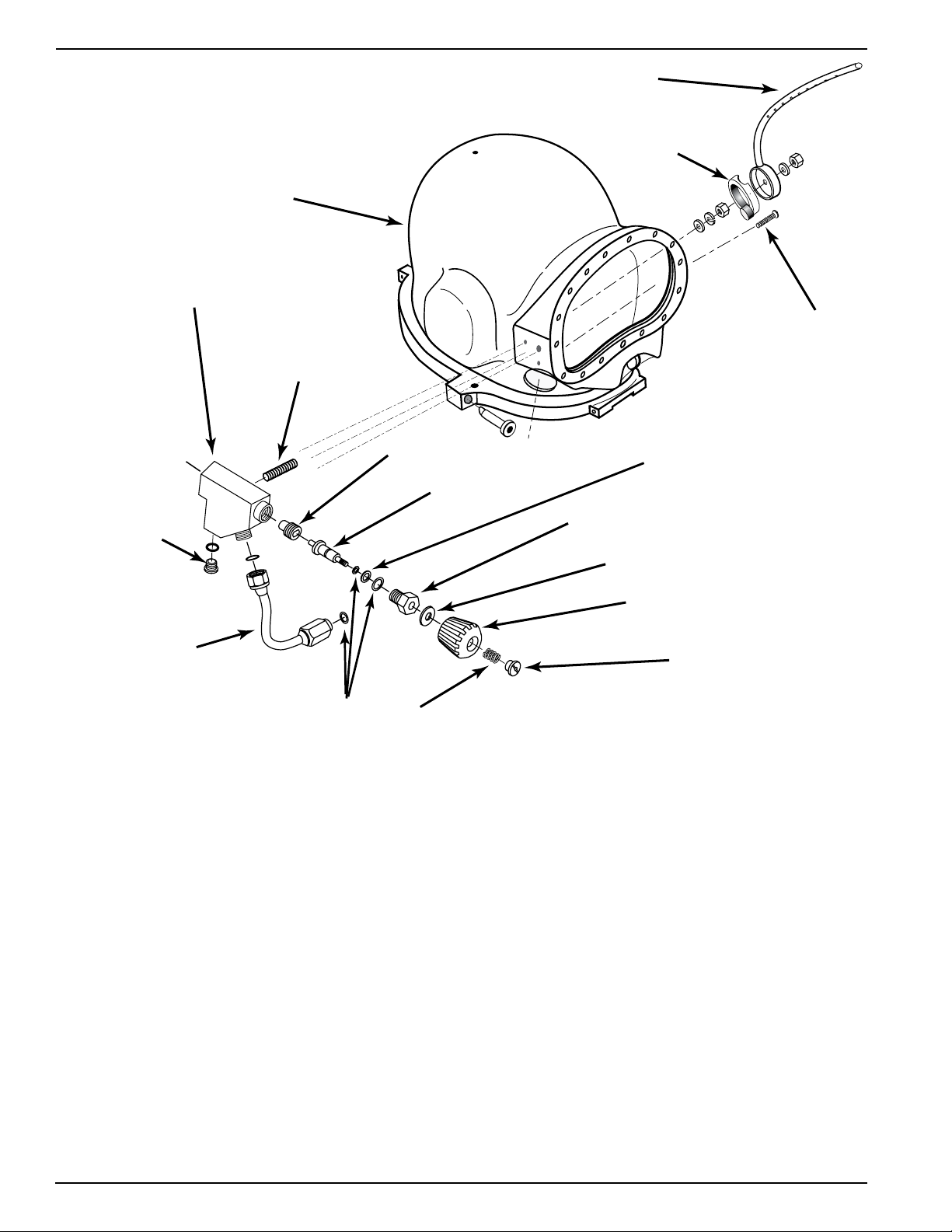
Components of the Side Block & Air Train
© Copyright 1970-2008 Kirby Morgan Dive Systems, Inc. All rights reserved. Document # 080508001
71
Kirby Morgan 37 & 57
WARNING
WARNING
WARNING
WARNING
WARNING
WARNING
Use silicone sealant in
a well ventilated area.
Do not breathe the
fumes from uncured
silicone sealant. These
fumes are dangerous
and can cause uncon-
sciousness. They can
also cause long term damage to body tissue. Read and follow all precautions listed
on the silicone sealant tube and Material
Safety Data Sheet.
DO NOT BLOCK
AIR OPENING!
If it is, it must be cleaned out prior to diving.
Do not dive the helmet until the sealant
has had time to cure. Check the directions on the tube of sealant for curing
time. If the helmet goes into the water
before the sealant has cured it could leak
through the side block mounting stud
hole, screw hole, or air flow hole. This
could lead to drowning.
If silicone sealant is blocking the air flow
into the helmet it must be cleaned out. If it
is not, the diver may not be able to properly defog the helmet or clear a flooded
helmet quickly. In addition, if the demand
regulator is not delivering air properly, the
diver cannot use the free flow system as
a source of breathing air. This could lead
to suffocation.
A generous application of silicone sealant must be
applied to the side block prior to installation on the
helmet shell. Use only Dow Corning™ RTV 732 Multi
Purpose sealant.
3) Slide the flat washer and the lock washer onto the
stud. Run the stud nut down the stud and tighten to
35 inch pounds (4 Newton meters). Do not over-
tighten!
4) Tighten the screw to the correct torque, 35 inch
pounds. Clean off all excess silicone sealant.
5) Place the air train gasket on the base of the air
train. The knob on the base of the air train gasket is
designed to cover the recessed hole where the bolt
that helps maintain the position of the air train is
installed. Slip the air train over the stud. Align the
air train with the upper edge of the view port opening
in the helmet shell.
6) Place the washer on the stud and tighten the nut
until the washer lays flush on the air train, 15 inch
pounds. Do not overtighten!
Avoid breathing
fumes from lacquer
thinner and use in a
well ventilated area.
Breathing fumes
can lead to nervous
system damage,
unconsciousness,
and death.
Avoid skin contact with lacquer thinner.
Wear rubber gloves. Lacquer thinner can
damage the nervous system.
Avoid eye contact with lacquer thinner. This chemical
is an irritant and may cause
tissue damage.
7) Test the side block prior to diving to ensure that no
silicone sealant is blocking the air flow to the helmet.
72
© Copyright 1970-2008 Kirby Morgan Dive Systems, Inc. All rights reserved. Document # 080508001
Kirby Morgan 37 & 57
7.4 Defogger Valve
7.4.1 Disassembly of the Defogger Valve
Tools Required:
3/8 inch Slotted Flat Blade Screwdriver
13/16 inch Open End Attachment on Torque
Wrench
The defogger valve components are disassembled as
follows:
1) First, unscrew the control knob lock nut and remove the spring, control knob, and washer.
2) Next, unscrew the bonnet. Its o-ring will come off
with it. The valve stem, o-ring, and washer usually
come out with the bonnet and can be pushed out of
the bonnet once removed from the side block.
3) If the stem remains in the side block body it can
be lifted out after the bonnet is removed.
4) The seat a ssembly can be unscrewed from the side
block body with the stem or a screwdriver.
7.4.2 Cleaning and Lubricating
1) Clean all the metal first in the soapy water solution
and then in a 50/50 dilute solution of white vinegar/
water. Rinse in fresh water.
2) Check the Teflon
®
se at for wear a nd /or conta mination, and replace if necessary. Damage such as a rough
face or cuts to the seat indicate it must be replaced.
3) The Teflon
®
washer and O-ring must be replaced
if worn.
Remove the defogger control knob.
The valve stem usually comes out with the bonnet.
4) Be sure to place a light coating of silicone grease
on all internal moving parts, O-rings, and washers.
However, do not lubricate the Teflon
®
seat, as this will
attract dust and debris.
5) Inspect the seat area inside the side block and
replace the block if damaged.
Clean all the metal parts to remove salts.
The seat should be removed for inspection.
© Copyright 1970-2008 Kirby Morgan Dive Systems, Inc. All rights reserved. Document # 080508001
73
Kirby Morgan 37 & 57
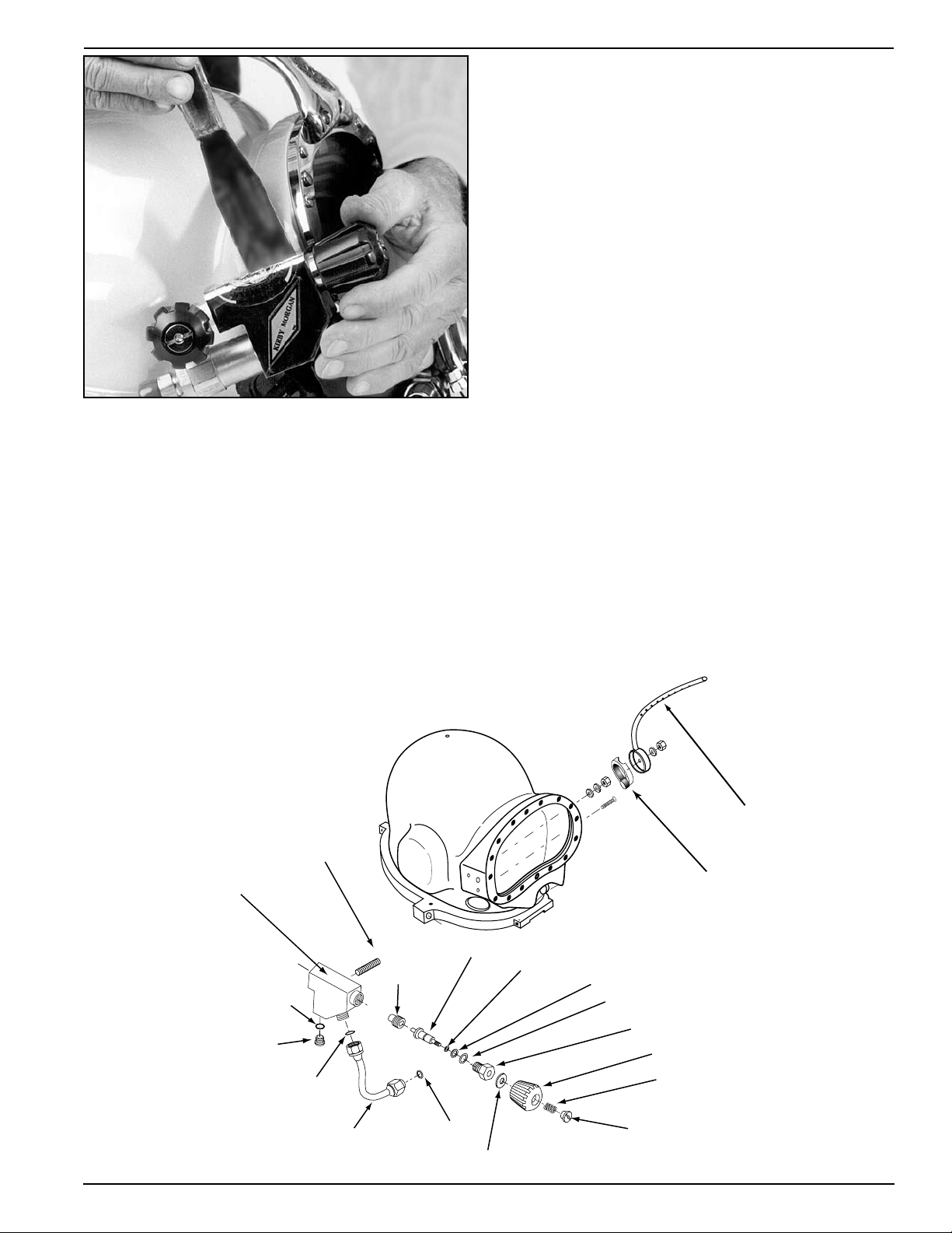
Side Block
Helmet
shell
Air Train
Air Train
Gasket
Stud
Bolt
Bent Tube
LP
Plug
Seat
Valve Stem
Bonnet
Washer
Knob
Spring
Nut
Teflon washer
O-ring
The Side Block assembly and it’s
associated parts.
7.4.3 Reassembly of the Defogger Valve
Tools Required:
3/8 inch Slotted Flat Blade Screwdriver
13/16” Open End Attachment on Torque Wrench
Minimum recommended replacement parts during
overhaul:
Washers, O-rings
1) Screw in the new seat assembly until it is even with
the front of the side block body.
2) Next, install the Teflon
the stem.
3) Insert the proper end of the stem into the seat
assembly and turn clockwise until the seat lightly
bottoms out. Leave the stem in place.
4) Lubricate the O-ring and install on the bonnet.
5) Slide the bonnet over the stem and thread the bon-
®
washer and O-ring onto
net into the side block.
6) Tighten the bonnet with a torque wrench to 100
inch lbs.
7) Place the new Teflon
on t he stem and rot ate t he stem counterclockwise until
the seat assembly tops out fully open. The control
knob must turn smoothly without any binding.
®
washer and the cont rol knob
Binding (or “hard spots”) in the rotation could be
an indication of a bent stem that should be replaced.
Replace the knob and or stem if the fit allows the valve
to rotate loosely more than 1/8
8) Install the new Teflon
the spring, and locknut. Tighten the locknut until it
is flush with the knob.
th
of a turn.
®
washer, new knob, and
74
© Copyright 1970-2008 Kirby Morgan Dive Systems, Inc. All rights reserved. Document # 080508001
7.5 Emergency Valve Assembly
WARNING
The Emergency valve control knob is not interchangeable with the defogger valve control knob.
The control knob for the emergency
valve and the defogger knob are not interchangeable. Use only the correct knob
for the appropriate valve.
Kirby Morgan 37 & 57
7.5.1 Disassembly of the Emergency Valve
Tools Required:
11/16 inch Open End Wrench
1 inch Open-end Wrench
Torque Wrench Attachments & Torque Wrench
3/8 inch Slotted Flat Blade Screwdriver
Soft Jaw Vice
Lubricant
Teflon Tape
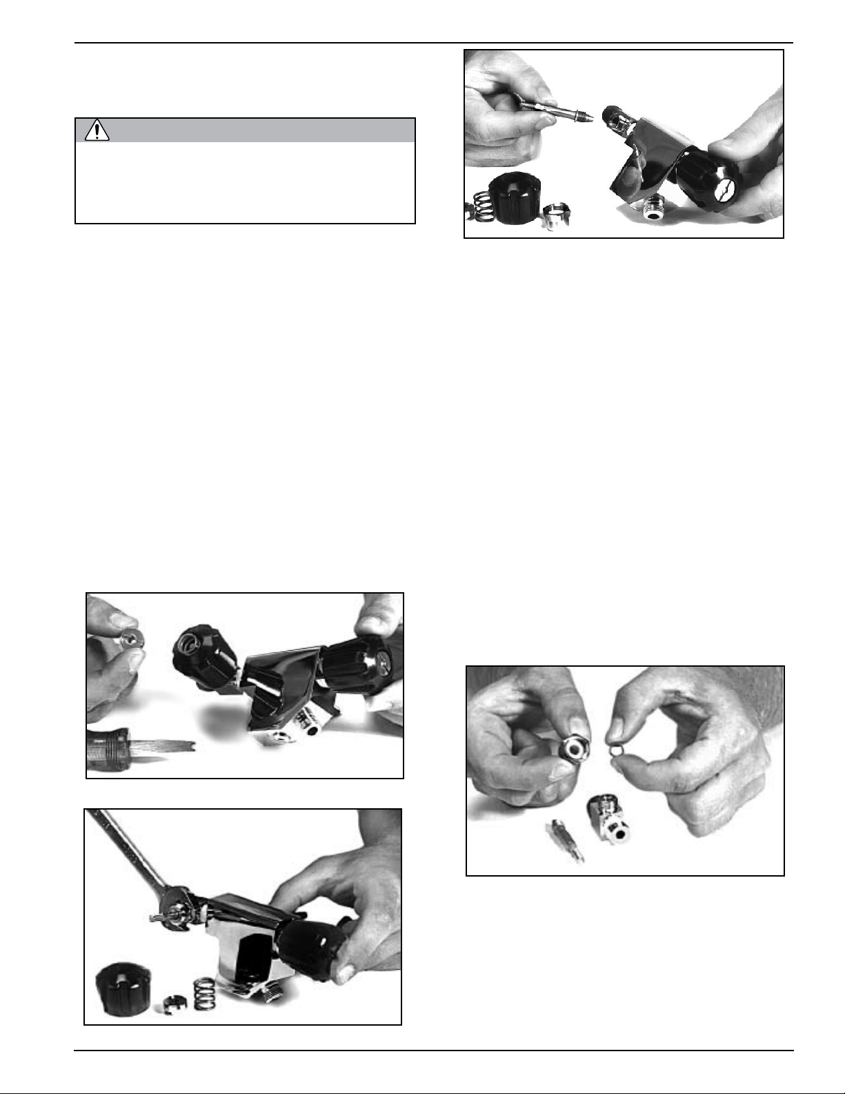
1) Remove the lock nut, spring, and knob.
2) Undo the packing nut, and remove the packing,
and washer.
3) When the packing nut is free of the threads of the
emergency valve body, back out the stem until it is
free of the emergency valve body.
Remove the valve stem.
7.5.2 Cleaning and Lubricating
1) Clean all the metal parts in a soap and water solution, followed by cleaning with a 50 /50 dilute solution
of white vinega r/water. Rinse with fresh water. Clean
all parts. See the cleaning instructions in Chapter 6.
2) Inspect the packing and washer for wear and replace if necessary. Normally the packing will last a
very long time and does not require replacement as
long as the valve operates smoothly and does not leak.
To replace the packing place the packing nut in a vise
and carefully work the packing out with a small screw
driver, taking care not to damage the threads of the
packing nut. Replace the washer if needed.
3) Inspect the stem seat for unevenness or wear and
replace if necessary. It must also be replaced if the
stem is bent. Damage will include damaged threads,
rounded flats that engage the control knob. Also
inspect the shaft to ensure the conical seat surface is
smooth and free of corrosion or damage.
Remove the lock nut, spring and knob.
Inspect the packing and washer.
4) Check the seat in the emergency valve body for
wear or unevenness, galling and corrosion. Check
the seat on the emergency valve stem. To clean up the
seat surface use a pencil eraser to buff the surface.
Inspect all threaded surfaces for damage. Replace the
emergency valve body if any damage is found.
Undo the packing nut.
© Copyright 1970-2008 Kirby Morgan Dive Systems, Inc. All rights reserved. Document # 080508001
75
Kirby Morgan 37 & 57
Valve Body
Valve Stem
Packing nut
Knob
Spring
Lock nut
Packing
Washer
5) To remove the emergency valve body from the
side block the one way valve assembly must first be
removed.
6) If the emergency valve body was removed, clean
and inspect the pipe thread and inspect for damaged
threads, cracking or distortion. Replace the emergency valve if any damage is present.
Re-tape threads with Teflon tape, 11/2 wraps starting
two threads back, tighten using good engineering
practice. To reinstall the emergency valve body onto
the side block, the one-way valve assembly must be
removed first.
7.5.3 Reassembly of Emergency Valve
1) Lightly lubricate the stem threads in the body as
well as the bonnet threads.
2) Replace the washer and packing on the stem , then
lightly lubricate the stem shaft and threads.
NOTE: There are two different packing (s) and
washers supplied in the kit (525-311), for rebuilding both the older style and the newer high flow
emergency gas valve. Match the removed packing
and washers to the new ones supplied and discard
the others.
3) Holding these components in place on the stem,
screw the stem into the emergency gas valve body.
Installing the packing nut on the valve stem.
4) Rotate the stem until it is seated all the way in then,
back it out -1/2 turn.
5) T
hread the packing nut onto the emergency valve
body. Run the nut in and tighten slightly with a
wrench.
6) Inspect the emergency gas valve knob for wear and
damage. Ensure the flats that engage the valve stem
shaft are not rounded, cracked or damaged. The valve
knob should not have rotational play greater than 1/8th
of a turn.
NOTE: This knob is not interchangeable with the
defogger valve knob.
7) Place the emergency gas valve knob onto the stem
76
The emergency valve
© Copyright 1970-2008 Kirby Morgan Dive Systems, Inc. All rights reserved. Document # 080508001
WARNING
The control knob for the emergency
WARNING
WARNING
valve and the defogger knob are not interchangeable. Use only the correct knob
for the appropriate valve.
and rotate the stem all the way out, then back again.
The rotation must be smooth. If “hard spots” or unevenness are felt during the rotation, the stem may
be bent and could need replacement.
8) Tighten t he pack ing nut with a torque wrench until
moderate resistance is felt when turning the knob.
Torque to 50 inch pounds after seating.
Kirby Morgan 37 & 57
the first thread. Apply the tape with slight tension to
allow the tape to fill into the threads.
Hand tighten the valve, then continue an additional 1-1/2
to 2 turns with a wrench keeping in mind the proper
alignment of the control knob to the side block. Also,
there should be at least one male thread visible. Check
to be certain the valve is tight by trying to loosen the
fit by hand.
DO NOT TIGHTEN
TH
AN NECESSARY!
OVERSTRESS THE PART AND CAUSE THE PART
TO FAIL.
THE VALVE BODY TIGHTER
OVER TIGHTENING MAY
9) Place the spring, and locknut onto the stem securing the knob.
10) Tighten the locknut until its top is flush with the
top of the knob. The assembly is now complete and
ready for testing.
NOTE: If the valve was removed from the side block
testing of the emergency gas valve is easily accomplished by attaching the valve, by itself in the shut
position, on to the bail-out whip from the first stage.
Pressurized to a minimum 135 p.s.i.g. (9.3 bar) using the EGS Cylinder and dropping it into a bucket
of clean water a minimum 30 seconds to check for
leaks.
11) Before wrapping the threads with pipe tape, check
the fit of the valve assembly pipe threads to the mating
threads of the side block. There should be 2 turns of
hand make up before needing to use a wrench.
Use only thin Teflon tape when installing
the Emergency Gas Supply valve in the
side block. Thick tape can lead to thread
damage, which may make it impossible
to install the EGS valve in the side block
properly. This could lead to a loss of
breathing gas.
If there is less make up, then the threads will need to be
chased with a 1/4” NPT tap to obtain the proper make
up. If thread chasing is required, the bent tube assembly,
the one way valve assembly and steady flow components
must all be removed and the side block body must be
thoroughly cleaned to remove any loose particles.
12) Before installing the valve assembly, wrap the pipe
threads with 1-1/2 turns of Teflon tape starting after
It is NOT necessary to have the control knob for the
emergency gas supply valve perfectly “square,” i.e., at
a 90 degree angle to the side block. Any angle is acceptable provide d t hat 1) the valve handle ca n b e tu r ned
easily and 2) the diver can locate the handle easily.
7.5.4 Leak Testing the EGS Valve
a) Attach supply whip from the EGS first stage to EGS
helmet valve.
b) Ensure the defogger valve knob is open and the EGS
Valve is shut.
c) Pressurize EGS Valve to a minimum of 135 p.s.i.g.
(9.3 bar) using the EGS cylinder as supply. Allow system pressure to stabilize, and then shut the EGS supply
cylinder valve. Note time and final stabilized system
pressure.
d) Perform the leak check for minimum of five minutes, using the mild soapy solution, per Chapter 6.
Ensure there is no gas flowing or pressure drop in the
system. There should be no visible signs of external
leakage if the valve is operating properly.
A leaking Emergency Gas Valve assembly
can cause the diver to exhaust his entire
EGS (bailout) without his knowledge. This
may lead the diver to mistakenly assume
his EGS supply is available when it is
not. This could lead to panic or drowning
in an emergency. Any worn or damaged
components must be replaced.
A submersibl e pressure gaug e
should always be used with the EGS system to help minimize this risk.
© Copyright 1970-2008 Kirby Morgan Dive Systems, Inc. All rights reserved. Document # 080508001
77
Kirby Morgan 37 & 57
WARNING
7.6 Bent Tube Assembly
7.6.1 General
The bent tube assembly provides breathing gas flow
from t he side block assembly to t he regu lator assembly
on the Kirby Morgan 37. Both ends of the bent tube
assembly disconnect for complete removal. The Oring and the Teflon O-ring should be replaced during
normal overhauls or any time these components are
deemed unserviceable.
These components do not require replacement during
field repairs providing a careful visual inspection does
not reveal wear or damage. All soft goods should be
carefully cleaned in accordance with Chapter 6 prior
to inspection for reuse.
7.6.2 Removal of the Bent Tube Assembly
Tools Required:
11/16 inch Open-end Attachment on Torque
Wrench
7/8 inch Open-end Attachment on Torque Wrench
7/8 inch Open-end Wrench
1) Always start removal of the bent tube at the side
block end. The free swiveling mount nut on this end
of the bent tube can be unthreaded completely and
can slide down the tube.
2) The inlet nipple has a jam nut that locks the mount
nut in place. With one wrench, hold the bent tube
mount nut. With another wrench, turn DOWN the
jam nut, backing it away from the mount nut. The
mount nut can then be rotated until free of the regulator inlet nipple threads. It can be pushed up the
bent tube.
3) With the two mount nuts free; the bent tube assembly can b e pul led straight out of the regulator in let
nipple. The bent tube assembly can be rotated back
and forth to aid removal.
7.6.3 Inspection of Bent Tube Assembly
Clean the bent tube in accordance with Chapter 6.
The O-ring at the regulator end should be clea ned and
inspected whenever the bent tube is removed.
Replace the bent tube if it is excessively scratched
dented or compressed deeper than 1/8 inch. If the
helmet has been used for burning jobs, carefully check
for erosion of the metal or severe corrosion. Replace
if any erosion is present or integrity is in question.
Keep in mind the bent tube is a critical component
that routs breathing gas to the helmet systems.
Always start removal at the side block end.
Loosening the jam nut.
78
© Copyright 1970-2008 Kirby Morgan Dive Systems, Inc. All rights reserved. Document # 080508001
Replace the O-ring on the bent tube if it is worn or
damaged.
Do not wrap the bent tube with tape,
ropework, springs, hose wrap, or other
items. This will prevent daily inspection of
the bent tube. In addition, some of these
items may trap moisture, which could lead
to corrosion and failure of the bent tube.
If the tube fails, this could lead to a rapid
depletion of the diver’s breathing gas supply. This could lead to serious personal
injury or death.

7.6.4 Installation of the
Bent Tube Assembly
Tools Required:
11/16 inch Open-end Torque Wrench Attachment
7/8 inch Open-end Torque Wrench Attachment
7/8 inch Open-end Wrench
Normal minimum replacement parts during overhaul:
O-ring, Teflon
®
ring
1) Lightly lubricate the bent tube O-ring and install
in the O-ring groove at the regulator end of the bent
tube, then install new Teflon® O-ring at the side
block end.
2) Push the regulator end of the bent tube assembly
into the inlet nipple. Slide it in until the side block
end of the tube is aligned with the threads for the
mount nut.
Kirby Morgan 37 & 57
3) Be sure the Teflon
®
O-ring is in place on the side
block end of the bent tube, then engage the threads
on the tube to the side block and hand tighten.
4) Start the “regulator to bent tube” mount nut onto
the inlet nipple of the demand regulator and run it in
by hand as far as it will go.
NOTE: Run the mount nut up on the inlet nipple
hand tight only.
5) Using a torque w rench, t ight en t he bent tube assembly mount nut onto the side block to (100 inch lbs).
6) Hold the mount nut on the end of the bent tube
with a wrench and tighten the jam nut against it with
a torque wrench to 40 inch pounds.
© Copyright 1970-2008 Kirby Morgan Dive Systems, Inc. All rights reserved. Document # 080508001
79
Kirby Morgan 37 & 57
7.7 SuperFlow 350
Demand Regulator
7.7.1 General Regulator Information
While the regulator systems on all K irby Morgan helmets a re simple a nd h ighly rel iable, the breat hing resistance will increase if the demand regulator on your
helmet is not maintained or adjusted properly. The
demand regulator must receive regular maintenance
to assure the best performance possible. However, in
the event the demand regulator is damaged, there is
always a backup supply of steady flow gas available
from the defogger valve.
If the regulator does not breathe easily, the diver cannot work hard and will tire rapidly. Simply put: If the
demand regulator does not work properly the diver
cannot work properly. This makes the maintenance
of the demand regulator assembly essential.
For the gas inlet valve and adjustment system to operate properly, the components in the demand regulator
MUST be in good condition and MUST be periodically inspected and adjusted.
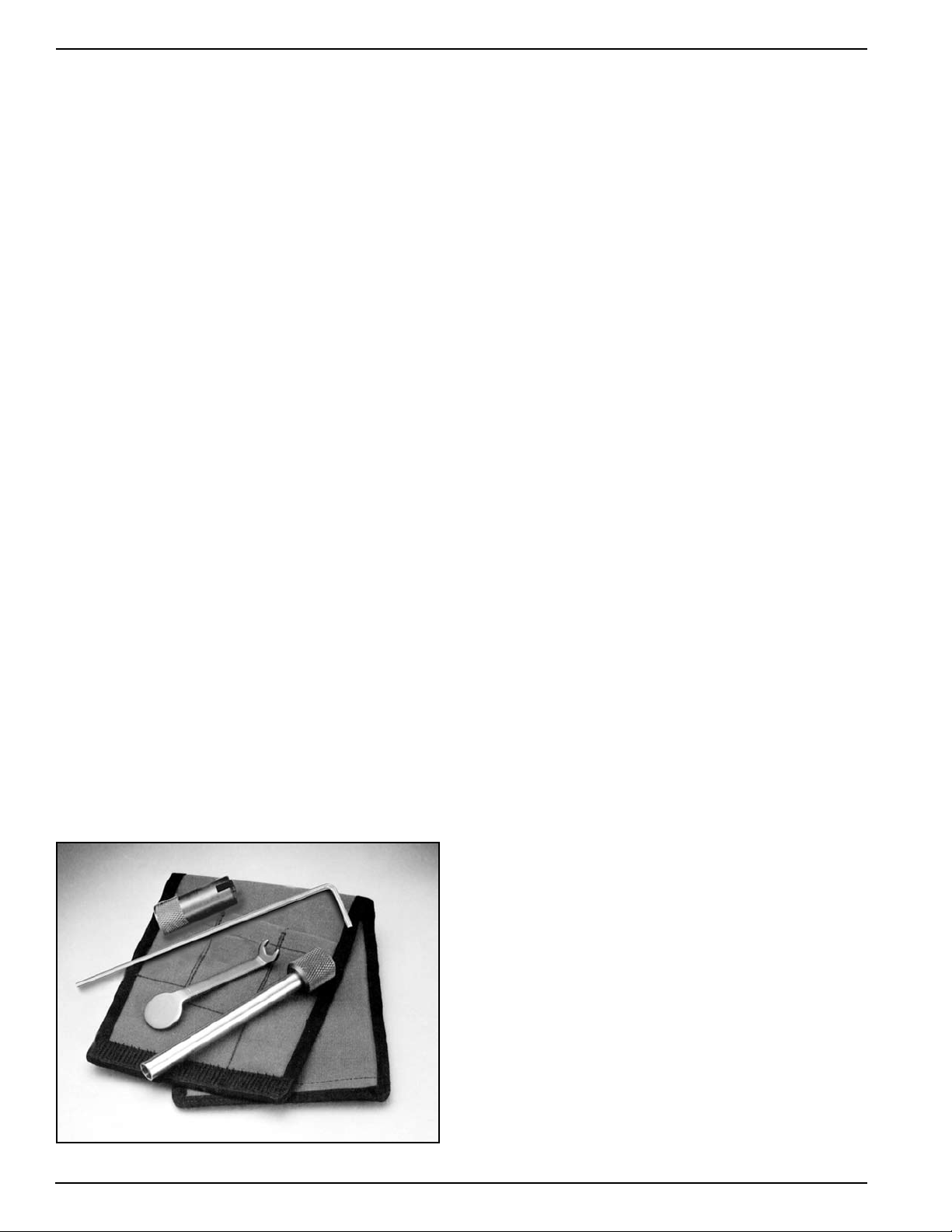
Four special tools, the inlet valve holder (Part #525-
616), the regulator adjustment wrench (Part #525-611),
the socket wrench (Part #525-612), and the castle
wrench (Part #525-618) should be used to work on
the SuperFlow 350 regulator whenever possible.
Disassembly, assembly, and adjustment can be done
without these tools, but the work is much easier and
the adjustment is better if these tools are used. The
above 4 tools are available together along with a tool
case. The “Tool Kit with Pouch” is Part #525-620.
This kit is included with each new Kirby Morgan
helmet that is equipped with the SuperFlow 350
regulator.
7.7.2 SuperFlow 350 Demand Regulator Test
for Correct Adjustment, Fully Assembled
To maintain optimum performance of the demand
regulator, it should be checked for proper function
and adjustment prior to commencement of diving
each diving day, in accordance with the KMDSI Daily
Set Up and Functional Checklist. See the Dive Lab
website (www.divelab.com) for the latest procedures
for set-up.
Check the regulator for adjustment and proper function with the assembly complete, and supplied with a
breathing gas supply pressure of 135 to 150 p.s.i.g.
NOTE: 135 to 150 p.s.i.g. over ambient is the standard supply pressure to be used when adjusting
all KMDSI helmets and band-mask equipped with
the SuperFlow 350 regulator. See Section 2.5 for
recommended pressures during use.
NOTE: When storing the helmet for any length of
time, ensure that the regulator adjustment knob is
turned “out ” fully cou nterclockwise to avoid st ressing
the bias springs. This will prolong the life of both the
inlet valve, seat, and bias springs.
1) Rotate the regulator adjustment knob in, towards
the regulator body.
2) Ensure the supply pressure is connected and properly adjusted to 135 to 150 p.s.i.g.
3) Turn on the gas supply.
4) Rotate the adjustment knob out counterclockwise
slowly, until a slight steady flow develops.
5) Slowly rotate the adjustment knob in clockwise,
until the free flow stops. Lightly depress the purge
button several times and ensure the gas flow has
stopped.
80
6) Lightly depress the purge button. There should be
bet ween 1/16” and 1/ 8” free travel i n the button before
gas flow starts. When the button is fully depressed, a
strong surge of gas must be heard.
7) If the purge button travels less than 1/16” or greater
than 1/8” before free flow is heard, the demand regulator requires internal adjustment, per this chapter.
Tool Kit with pouch - Part #525-620.
© Copyright 1970-2008 Kirby Morgan Dive Systems, Inc. All rights reserved. Document # 080508001
Kirby Morgan 37 & 57
WARNING
7.7.3 Inspection of SuperFlow 350
Regulator Body Interior
Tools Required:
1/4 inch Flat Blade Attachment on Torque Screwdriver
Remove the demand regulator clamp.
1) Remove the demand regulator clamp by removing
the clamp screw.
2) Lift off the regulator cover and diaphragm.
3) Clean the diaphragm with the soapy solution, per
Chapter 6 and wipe dry. Inspect the diaphragm for
holes, tears or any signs of deterioration by holding it
up to a white light and stretching and pulling. Check
for a good bond between the metal disc and the silicone. Replace diaphragm if any doubt exists.
NOTE: Older regulator clamps, when properly
torqued, had a gap of approximately 1/32” to
1/16” between the retaining clamp surfaces when
fully tightened. All new clamps when properly
torqued, have little or no gap between the retaining clamp surfaces.
7.7.4 SuperFlow 350 Demand Regulator
Bias Adjustment
Servicing, Demand Regulator
on the Helmet
Note: This procedure should be used when replacing the O-ring on the adjustment shaft and or
cleaning and lubricating the shaft threads during
field repairs of the demand regulator on the helmet.
Start at the adjustment knob end of the regulator:
To ols Required:
3/4 inch Open-end Wrench Attachment on Torque
Wrench
3/32 inch Punch & Small Block of Wood
Ball-Peen Hammer
Regulator Adjustment Tool Kit, Part #525-620
Torque Wrench
1) Unscrew the regulator adjustment knob until it
stops. If the knob wobbles as you turn it, or is extremely hard to turn, the shaft is bent and needs to
be replaced.
4) Inspect the interior of the demand regulator body
for damage, corrosion and cleanliness. Clean the interior of the regulator body if necessary per Chapter
6.
6) Reinstall the diaphragm, cover, and clamp. Tighten
the clamp screw to the recommended torque to 12
inch pounds using a torque screwdriver.
Use only replacement diaphragms manufactured by Kirby Morgan. Use of other
diaphragms may degrade performance
and may cause increased breathing resistance. This can lead to fatigue and the
inability to work at full capacity.
© Copyright 1970-2008 Kirby Morgan Dive Systems, Inc. All rights reserved. Document # 080508001
Screw the regulator adjustment knob out for
removal.
2) Loosen the nut, then rotate the adjustment knob
counterclockwise until the adjustment knob and the
adjustment shaft are free.
3) Remove the spacer, springs, and piston. At this
point the threads can be cleaned and lubricated as
well as the adjustment shaft.
4) Punch out the roll pin using a 3/32 punch. Use a
block of wood with a 1/4” hole drilled through it to
support the knob. Position the knob so the roll pin
81
Kirby Morgan 37 & 57
Shake out the spacer, spring set, and piston.
is over the hole. The adjustment knob can be held
against the wood block allowing the roll pin to be
driven into the 1/4” hole.
5) Remove the adjustment knob, the washer and Oring.
Inspect the washer and o-ring.
9) Inspect the inside of the adjustment tube on the
regulator body to be sure there is no corrosion and
the adjustment assembly can travel freely. Ensure the
alignment t ube is not bent or misaligned from impact,
and that the threads are clean.
NOTE: If the inside of the adjustment tube is corroded, this indicates saltwater intrusion into the
adjustment tube and assembly. The demand regulator requires removal from the helmet and cleaning
per this Chapter.
7.7.5 Reassembly of the SuperFlow 350
Regulator Adjustment System
Tools Required:
3/4 inch Open-end Wrench Attachment on Torque
Wrench
Silicone grease, or oxygen compatible grease if used
for oxygen service.
NOTE: If the spacer and the spring set are stuck,
this could indicate corrosion or possible saltwater
intrusion into the adjustment tube and assembly,
or that the adjustment tube is bent. The demand
regulator should be removed from the helmet and
cleaned and inspected, per this Chapter..
6) Carefully inspect all parts for corrosion, paying
particular attention to threaded surfaces and the
spring set. Clean and lightly lubricate parts per the
instructions in this chapter.
NOTE: Carefully inspect the adjustment shaft to
ensure it is straight, Check for damaged threads.
Replace the adjustment shaft if any damage is
found. Replace the O-ring.
7) Replace washer.
8) Replace the O-ring.
82
© Copyright 1970-2008 Kirby Morgan Dive Systems, Inc. All rights reserved. Document # 080508001
1) Lightly lubricate the piston and spacer and place
the piston back in the regulator adjustment tube, followed by the spring set, and spacer.
2) Lightly lubricate the adjustment shaft end and
threads, install the washer and the lightly lubricated
O-ring on the adjustment shaft.
3) Slip the packing nut over the adjustment shaft followed by the adjustment knob.
4) Hold the shaft and rotate the knob until the pin
holes line up. Use the inlet valve holder from the
regulator tool kit to accurately align these holes. Using a small hammer drive the retaining pin back into
place, until it is flush with the surface of the adjustment knob.
5) Screw the adjustment knob assembly clockwise
back into the regulator body leaving enough packing
nut exposed to get the wrench on it.
 Loading...