

Page 1

VI-MMXII Page 1
TRUCK
MOUNTED
OPERATION AND MAINTENANCE
MANUAL
TRUCK AND
TRAILER
MOUNTED
V
E
R
T
I
C
A
L
FEED
MIXER
Kirby Manufacturing
P.O. Box 989
Merced, California; 95341-0989
(209)-723-0778 Kirby Mfg.
TRAILER
MOUNTED
Page 2

VI-MMXII Page 2
TABLE OF CONTENTS
SECTION
i. WARRANTY
ii. CHECKLIST / SIGN-OFF SHEET
1.0 SAFETY PROCEDURES
2.0 MIXER STRUCTURE AND TRAILER
3.0 MAIN AUGERS, SHAFTS, AND BEARINGS
4.0 SPROCKETS AND CHAINS
5.0 GEARBOXES
6.0 DRIVELINES AND POWER TAKEOFFS
7.0 MAIN HYDRAULIC SYSTEM
8.0 LUBRICATION AND MAINTENANCE
9.0 ELECTRONIC SCALES AND LOADCELLS
10.0 EQUIPMENT OPERATIONS
11.0 SPARE PARTS
12.0 APPENDIX
Copyright: rev.: 8/22/2017
Page 3

VI-MMXII Page 3
KIRBY MANUFACTURING, INC.
NON-TRANSFERRABLE LIMITED WARRANTY
GENERAL TERMS AND CONDITIONS:
KIRBY MANUFACTURING, INC. (henceforth referred to as KMI), hereby warrants to the
original purchaser of a newly manufactured KMI product, that all new KMI products are guaranteed
against defects in materials or manufacture under normal use for a period of one year (1) or duty
cycle of 3000 hours (whichever comes first) from the original in-service date.
Improper Activity will void this limited warranty. “Improper Activity” includes any, and all, of the
following: Installation by anyone other than KMI or its authorized agent, improper installation,
use/operation/maintenance other than in accordance with KMI’s instructions, tampering, neglect or
damage by the application of force, acts of vandalism, accidents, misuse, abuse, repair/alteration or
adjustment by anyone other than KMI or its authorized agent.
FOR THE WARRANTY TO BE IN EFFECT: The warranty registration form must be signed,
dated and submitted to KMI within 15 days of the delivery date by the end user. If not returned, the
warranty period begins from the date the equipment was invoiced to the dealer.
This warranty is subject to any existing conditions of supply which may directly affect our ability to
obtain materials or manufacture replacement parts. This warranty shall in no way make KMI liable
for personal injuries or damages, loss of time or expense of any kind either direct or indirect resulting
from part failure or defect.
KIRBY MANUFACTURING, INC. DISCLAIMS ALL OTHER WARRANTIES, INCLUDING,
WITHOUT LIMITATION, ANY WARRANTIES, EITHER EXPRESSED OR IMPLIED, OF
MERCHANTABILITY OR FITNESS FOR A PARTICULAR PURPOSE. NO AGENT OR
EMPLOYEE OF KIRBY MANUFACTURING, INC IS AUTHORIZED TO EXTEND ANY
OTHER WARRANTY OR OBLIGATION. THERE ARE NO WARRANTIES THAT EXTEND
BEYOND THE DESCRIPTION ON THE FACE HEREOF.
WARRANTY PROVISIONS: During the warranty period (12 months or 3,000 hours), KMI will
repair or replace parts of the product that prove defective because of improper material or
workmanship, under normal use and maintenance. This warranty is subject to the following
provisions:
1. Labor is covered for a period of 90 days from the original in-service date, except defects in
workmanship, which is covered for the entirety of the warranty (12 months or 3,000 hours).
2. Labor will be paid at the dealer’s standard hourly rate.
3. KMI will pay for standard ground shipping of parts within 90 days of the original in-service
date.
a. The shipping carrier will be at the discretion of KMI.
b. All priority shipping is the responsibility of the dealer or customer.
4. All warranty work requires a KMI warranty claims form to be filled out and returned with
all required documentation.
5. Warranty forms must be requested within 48 hours of the first business day after the repair.
6. All warranty claims must be submitted within 30 days of the warranty claim form date.
Page 4

VI-MMXII Page 4
7. Replacement parts will have a 90-day warranty or the remainder of the KMI warranty period,
whichever is longer. Parts must be installed by an authorized dealer or agent of KMI.
8. Any removed parts must be marked with serial number of the unit, date of repair and warranty
number.
9. Parts must be held by the dealer upon request of KMI for 30 days.
10. Parts may be requested by KMI to be returned to KMI or a supporting vendor.
a. Supporting vendor - A return goods authorization (RGA) and warranty claim number
will be issued.
b. KMI - Warranty claim number will be issued.
11. If deemed defective by KMI, parts with an RGA/Warranty claim number will be reimbursed,
replaced or credited back to the dealer at the net dealer cost.
12. Parts invoice for warranty goods received will be requested with warranty. If a part is
purchased outside of KMI proof of purchase will be required for reimbursement.
13. The following are not covered under this warranty:
c. Overtime, freight and travel.
d. Rental fees for loaner equipment to the end customer.
e. Other out of pocket expenses incurred during downtime.
f. Overnight/priority shipping.
g. Damages or repairs to tractors used with KMI equipment.
h. Truck and all truck parts/components (truck mounted models).
i. Normal wear and tear for normal replacement parts, cutting knives, exterior finish,
chains, hydraulic oil & filters, belts, sprockets, u-joints etc.
j. Scale Systems have their own warranty and are not included in Kirby's limited warranty
coverage. The warranty stated by the scale manufacturer will be honored by KMI. This
does not include any freight, service calls or loaner unit for the specified repair. Scale
warranty is outlined in the Scale System’s owner's manual.
k. All parts requiring periodical maintenance, that have not been (but not limited to):
➢ Greased (bearings, PTO & driveline u-joints).
➢ Nuts and bolts tightened.
➢ Chains adjusted.
➢ Oil changed.
➢ Filter changed.
➢ Hydraulic hoses tightened.
14. Tires, wheels and batteries have a limited warranty of 3 months from the date of original sale
and warranty acceptance form. This includes oil seals for the axle hub. This does not include
any flats or damage caused by negligent use or foreign objects.
15. Electrical switches and controls installed by KMI are covered against defect in workmanship
for a period of one year under normal use. Part component switches are covered for 30 days.
PRODUCT IMPROVEMENTS: KMI reserves the right to make improvements and changes in
material and / or design of its products with no obligation to incorporate such improvement into
previously manufactured equipment.
Page 5

VI-MMXII Page 5
DEALERS RESPONSIBILITIES
1. Instruct the customer in the safe operation and servicing of the unit.
2. Review the owner's manual with the customer and ensure the customer understands the
complete operation, service, safety procedures and warranty of the unit.
3. Ensure customer signs and sends warranty registration to KMI within 15 days of delivery of
unit.
4. Customer should be advised to have failed parts repaired or replaced immediately upon
failure and that continued use could result in additional damage and excessive wear, voiding
the warranty.
5. Follow correct warranty procedures including but not limited to notifying warranty
department at KMI (209-723-0778) & submitting completed warranty claim form to KMI
within the specified time as set forth under the “Warranty Provisions” section.
6. Perform warranty and service repairs.
7. ALL DEALERS MUST WARRANTY THEIR TECHNICIAN'S WORK TO THE
PURCHASER AND MUST INDEMNIFY KMI FROM SUCH CLAIMS.
DELAYED WARRANTY REPAIRS
Warranty repairs should be scheduled and performed as soon as possible after notification of the
dealer to KMI. There may be extenuating circumstances that require the availability of repair parts
necessary to complete the repairs. In those cases, the dealer must notify KMI, in writing of the
extenuating circumstance and advise that the continued use of the product will not add to the
warranty claim. These claims, pre-approved by KMI, will then be processed as if the product is still
within the warranty period.
DENIED CLAIMS
Dealers will be notified of a denied claim in writing that will state the reason for the denial. The
dealer has the right to appeal this claim and must do so within 30 days of notification of denial. If
there has been no appeal within the 30-day period the claim will be considered closed.
Questions or comments? Contact Us:
Kirby Manufacturing, Inc.
P.O. Box 989
Merced, CA – 95341-0989
PH: (209) 723-0778
Fax: (209) 723 -3941
Email: rwallace@kirbymfg.com
Page 6

VI-MMXII Page 6
OPTIONAL EXTENDED WARRANTY
As a onetime offer, KMI offers the owner of a newly manufactured Kirby feed mixer the option to
purchase an extended warranty policy. This extended warranty policy offers a total of 3 years of
coverage (one-year standard warranty plus two years beyond the standard warranty). This extended
warranty policy must be purchased at the time of equipment sale and will go into effect upon initial
equipment start-up. A completed extended warranty acceptance documentation is required for the
extended warranty to be in effect.
This extended warrant policy covers the replacement parts itemized below:
1. Hydrostatic hydraulic pumps
2. Hydraulic motors for planetary
3. Planetary gearboxes
The following items are NOT covered under this extended warranty:
1. Hydraulic auxiliary pump (pump for door ram and crossfeed motor)
2. Hydraulic Oil
3. Hydraulic Cooling systems including hydraulic fan motors.
The general terms and conditions of the standard warranty also apply to the extended warranty in
addition to the special terms and conditions as listed below. This policy requires the equipment
owner to take and send in oil samples at predetermined time intervals or have an authorized Kirby
Service agent maintain and record all service schedules according to owner's manual.
These time intervals are as follows:
1. Gearbox oil samples every 6 months or 1,000 hours whichever comes first. (plus initial
sample taken 50 hours after start-up)
2. Hydraulic system oil samples every 3 months or 500 hours, whichever comes first.
These samples are to be sent in by the equipment owner to "WEARCHECK" laboratories for
analysis. "WEARCHECK" laboratories will analyze the samples and send a complete report to the
equipment owner stating the condition of the oil, as well as make recommendations about any
concerns they may see regarding the condition of the oil. It is the equipment owner's responsibility
to maintain the best oil condition in accordance with "WEARCHECK" laboratories
recommendations.
(Note: sample bottles are pre-addressed to "WEARCHECK" laboratories. It is the equipment
owner's responsibility to pay all mail charges to send samples to "WEARCHECK" laboratories)
Page 7

VI-MMXII Page 7
Proration with limitations of the planetary gearbox with extended warranty
Shaft seals and O-rings of the planetary gearbox are warranted for only one year and not subject to
the proration of the planetary. Prices based on suggested list price of planetary.
1. 1 to 12 months or 3,000 hours of usage, KMI at its sole discretion will replace or repair (parts
and labor) defective gearbox. Included are shaft seals and O-rings (100% replacement with
labor cost)
2. 13 to 24 months or 6,000 hours of usage, KMI at its sole discretion will replace or repair
(parts and labor) (75% of cost replacement and 75% of labor cost).
3. 25 to 36 months or 9,000 hours of usage, KMI at its sole discretion will replace or repair
(parts and labor) (50% of cost replacement and 50% of labor cost).
Equipment owner's responsibilities to maintain warranty
1. Purchase all sample bottles when purchasing equipment
Mechanically driven unit: 18 sample kits (6-2 speed, 12-planetary)
Hydraulically driven unit; 24 sample kits; (12-hydraulic system, 12-planetary)
4. Perform regular maintenance as specified in the Operation and Maintenance Manual
5. Take and send oil samples into WEARCHECK per time intervals stated above
6. Review oil reports and take corrective actions per WEARCHECK recommendations
7. All warranty claims must be accompanied with hard copies of the WEARCHECK reports
Any replacement provided under this warranty will be warranted for the remainder of the warranty
period applicable to the product in which it is installed or which it replaces.
OPTIONAL EXTENDED WARRANTY
Business Name: Date:
Model Type: Serial No:
Page 8

VI-MMXII Page 8
1.0 SAFETY PROCEDURES
When inspecting the machine all power must be shut off and secured.
Do not attempt to work on machine when machine is running.
Caution must be used when checking rotating parts under power. It is advisable to have two (2)
persons present when checking for safety. The second person should be positioned by a stop
switch so the machine can be stopped immediately in case of an emergency.
Do not leave machine unattended while in operation.
Be sure all guards and safety devices are in place.
Scale service requires special cautions-See section 9
Caution: The tractor power take-off (PTO) drive line should be removed from the tractor and the
key removed prior to servicing or working on the mixer unit.
Caution: The truck engine should be shut off and keys removed and P.T.O. disengaged when
servicing or working on the mixer unit.
SAFE OPERATIONS:
Operation of this mixer/feeder shall be limited to competent and experienced persons. In
addition, anyone who will operate or work around a mixer/feeder must use good common sense. In
order to be qualified, he or she must also know and meet all other qualifications, such as:
1. Some regulations specify that no one under the age of sixteen (16) may operate power
machinery. It is your responsibility to know what these regulations are in your area and/
or situation.
2. Current OSHA regulations state in part: At the time of initial assignment and at least
annually thereafter, the employer shall instruct EVERY employee in the safe operation
and servicing of all equipment with which the employee is, or will be involved.
3. Unqualified persons are to STAY OUT OF THE WORK AREA.
4. A person who is qualified to operate the machinery should be trained in and/or have read &
understood all operating and safety procedures.
FAILURE TO READ THIS MIXER/FEEDER MANUAL AND ITS SAFETY
INSTRUCTIONS ARE A MISUSE OF THE EQUIPMENT.
Page 9

VI-MMXII Page 9
SAFETY
IMPORTANT SAFETY PRECAUTIONS
These operating and maintenance instructions contain safety information to:
• make you aware of the hazards associated with the machine
• inform you of the risk of injury associated with those hazards
• tell you how to avoid or reduce the risk of injury.
TAKE NOTE: THE BELOW SAFETY ALERT SYMBOL FOUND THROUGHOUT THIS
MANUAL IS USED TO CALL YOUR ATTENTION TO INSTRUCTIONS INVOLVING
YOUR PERSONAL SAFETY AND THE SAFETY OF OTHERS. FAILURE TO FOLLOW
THESE INSTRUCTIONS CAN RESULT IN INJURY OR DEATH.
THIS SYMBOL MEANS:
-ATTENTION
-BECOME ALERT
-YOUR SAFETY IS INVOLVED
SIGNAL WORDS: Note the use of the signal words DANGER, WARNING, and CAUTION with
the safety messages. The appropriate signal word for each has been selected using the following
guidelines:
DANGER: Indicates an imminently hazardous situation that, if not avoided, will result in serious
injury or death. This signal word is to be limited to the most extreme situations typically for machine
components which, for functional purposes, cannot be guarded.
WARNING: Indicates a potentially hazardous situation that, if not avoided, will result in serious
injury or death, and includes hazards that are exposed when guards are removed. It may also be used
to alert against unsafe practices.
CAUTION: Indicates a potentially hazardous situation that, if not avoided, may result in minor or
moderate injury. It may also be used to alert against unsafe practices.
If you have questions not answered in this manual or require additional copies or the manual is
damaged, please contact your dealer or Kirby Manufacturing, P.O. Box 989, Merced, California;
Phone number (209)-723-0778.
Page 10

VI-MMXII Page 10
OPERATING PRECAUTIONS & INSTRUCTIONS
A. Check to see that no obstructions are present in the mixer prior to start up.
B. Before loading, run the mixer empty and check all operations.
C. Do not overload the mixer.
Maximum load is 16,000LB for 800 cu.ft. single axle mixer.
Maximum load is 30,000LB for 1000+ cu.ft. tandem axle mixer.
Maximum load is determined by weight, not volume.
D. Be sure all shields are in place before operation.
E. Use common sense when operating equipment.
ALWAYS REMEMBER SAFETY FIRST: The careful operator is the best operator. Most
accidents are caused by human error.
Certain precautions must be observed to prevent the possibility of injury or death.
DO NOT ALLOW PERSONNEL OTHER THAN THE TRAINED AND QUALIFIED
OPERATOR NEAR THE MACHINE.
NEVER START MACHINE UNTIL ALL GUARDS AND SAFETY SHIELDS ARE
IN PLACE.
DO NOT CLEAN, ADJUST OR LUBRICATE THE MACHINE WHILE IT IS IN
MOTION, ( ALWAYS turn off and remove keys prior to performing maintenance on
the machine)
BEFORE STARTING TRACTOR ENGINE, BE SURE PTO SHIELDS TURN
FREELY.
LOOSE CLOTHING SHOULD NOT BE WORN BY ANYONE NEAR THE
MACHINE
Page 11

VI-MMXII Page 11
EQUIPMENT SAFETY GUIDELINES
Safety is a key concern when designing and developing a new piece of equipment. Designers and
manufactures build in as many safety features as possible. However, every year many accidents
occur which could have been avoided by a few seconds of thought and a more careful approach to
handling equipment. You, the operator, can avoid many accidents by observing the following
precautions in this section. To avoid personal injury, study the following precautions and insist those
working with you, or for you, follow them. Perform regular safety audits to ensure adherence.
To provide a better view, certain photographs or illustrations in this manual may show an assembly
with a safety shield removed. However, equipment should never be operated in this condition. Keep
all shields in place. If shield removal becomes necessary for repairs, replace the shield prior to use.
Replace any CAUTION, WARNING, DANGER or instruction safety decal that is not readable
or is missing.
Do not attempt to operate this equipment under the influence of drugs or alcohol.
Review the safety instructions with ALL users annually.
This equipment is dangerous to children and persons unfamiliar with its operation. The operator
should be a responsible adult familiar with farm machinery, and trained in this equipment’s
operations. Do not allow persons to operate or assemble this unit until they have read this manual
and have developed a thorough understanding of the safety precautions and of how it works.
To prevent injury or death, use a tractor equipped with a Roll Over Protective System (ROPS). Do
not paint over, remove or deface any safety signs or warning decals on your equipment. Observe all
safety signs and practice the instructions on them.
Never exceed the limitations of a piece of machinery, in its ability to do a job, or to do so Safely! If
in question - DON’T TRY IT!
LIGHTING AND MARKING
It is the responsibility of the customer to know the lighting and marking requirements of the local
highway authorities and to install and maintain the equipment to provide compliance with the
regulations. Add extra lights when transporting at night or during periods of limited visibility.
Page 12
VI-MMXII Page 12
KEEP ALL SHIELDS IN PLACE
Do not operate mixer/feeder without safety shields in place.
Rotating parts can crush or dismember causing personal injury or
death.
Disconnect PTO driveline before removing shields for adjustment
or service.
OPERATE MIXER/FEEDER SAFELY
Rotating parts can entangle or strike people, resulting in personal
injury or death.
Never enter a mixer/feeder while in operation.
Operate the mixer/feeder from the operator’s seat only.
Do not exceed load capacity of the mixer/feeder. (See loading
instructions).
Reduce speed when turning or traveling on rough terrain.
Avoid traveling over or near loose fill, rocks, ditches or holes.
Keep transmissions in gear when traveling downhill.
KEEP RIDERS OFF MIXER/FEEDER
Keep riders off.
Riders are subject to injury such as being struck by foreign
objects, falling into the mixer and by being thrown off. Riders
also obstruct the operator’s view, resulting in the machine
being operated in an unsafe manner.
MOVING PARTS KEEP
ALL SHIELDS IN PLACE
BEWARE OF
KM 01
ROTATING AUGER
HAVE SPOUT IN UP
POSITION WHEN MIXING
KEEP HANDS AWAY
FAILURE TO HEED
WILL RESUL IN
PERSONAL INJURY
OR DEATH
KM 03
Page 13
VI-MMXII Page 13
STAY CLEAR OF ROTATING DRIVELINES
Entanglement in rotating driveline can cause serious injury or
death.
Keep tractor master shield and driveline shields in place at all
times. Make sure rotating shields turn freely.
Wear close fitting clothing. Stop the engine and be sure PTO
driveline is stopped before making adjustments, connections, or
cleaning out PTO driven equipment.
AVOID HIGH-PRESSURE FLUIDS
Escaping fluid under pressure can penetrate the skin causing serious
injury or death.
Avoid the hazard by relieving pressure before disconnecting hydraulic
or other lines. Tighten all connections before applying pressure.
Search for leaks with a piece of cardboard. Protect hands and
body from high pressure fluids.
If an accident occurs, see a doctor immediately. Any fluid injected
into the skin must be surgically removed within a few hours
or gangrene may result. Doctors unfamiliar with this type of injury
should reference a knowledgeable medical source.
SERVICE AND ADJUSTMENT
OF HYDRAULIC SYSTEM
SHOULD ONLY BE PERFORMED
BY QUALIFIED PERSONNEL.
IMPROPER ADJUSTMENT COULD
CAUSE SERIOUS INJURY,
DAMAGE TO SYSTEM,
AND VOID WARRANTY.
DO NOT WORK ON
WITHOUT DISCONNECTING
POWER SOURCE
KM 07
Page 14

VI-MMXII Page 14
PREPARING TRACTOR FOR TRAILER MIXER
IMPORTANT: Drive components can be damaged from excessive speed. Do not operate tractor at
speeds in excess of recommended PT0 rpm.
This feed mixer may be equipped with either a 1000 RPM or a 540 RPM driveline.
Match tractor PTO with the feed mixer driveline.
IMPORTANT: To prevent driveline damage, adjust tractor drawbar to recommended setting.
Disengage power to tractor PTO before turning tractor.
Remove clevis if equipped. Turn offset drawbar down.
Adjust drawbar length.
ADJUST TRAILER HITCH CLEVIS
Mixer should be approximately level when attached to tractor.
SAFETY DECAL CARE
Keep safety decals and signs clean and legible at all times.
Replace safety decals and signs that are missing or have become illegible.
Replaced parts that displayed a safety sign should also display the current sign.
Safety decals or signs are available from your dealer or Kirby Manufacturing.
Page 15
VI-MMXII Page 15
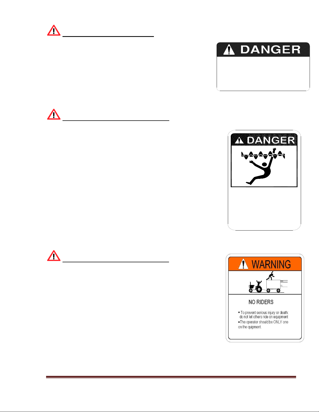
REPLACEMENT SAFETY DECALS
Immediately replace all and any worn or damaged Safety Decals. When ordering replacement
decals please provide the unit’s serial and model number.
Figure A Figure B
DANGER, Rotating Parts WARNING, Run-Away Hazard
Part No. KM-09 Part No. W-300
Figure C Figure D
WARNING To prevent Serious Injury WARNING, Crushing Hazard
Part No. W-100 Part No. W-200
Disengage PTO before
servicing, cleaning, or
clearing a clogged machine.
Stay off machine when it's
running.
Machine can be hazardous
in the hands of an
UNFAMILIAR, UNTRAINED, or
COMPLACENT operator.
Don't risk INJURY or DEATH.
KM 09
down steep grades.
RUN-AWAY HAZARD
To prevent serious injury or death:
Shift to lower gear before going
Keep towing vehicle in gear at
Never exceed a safe travel speed.
all times.
W-300
To prevent serious injury or death:
Read and understand owner's
manual before using. Review safety
precautions annually.
No riders allowed when transporting.
Securely attach to towing unit. Use
a high strength appropriately sized
hitch pin with a mechanical retainer
and attach safety chain.
Do not exceed 20 mph (33kph).
Slow down for corners and rough
terrain.
Do not drink and drive.
Before moving running gear, be sure
required lights and reflectors are
installed and working.
Before maintenance or repair, stop
vehicle, set parking brake, and
remove ignition key.
Place safety stands under frame and
chock wheels before working on
tires or running gear.
Maintain wheel bolts at torque as
recommend in the manual.
If equipped with brakes, maintain
proper adjustment.
W-100
CRUSHING HAZARD
To prevent serious injury or death:
Keep hands and body out of hitch
area when attaching towing vehicle.
Keep body clear of crush point
between towing vehicle and load.
W-200
Page 16

VI-MMXII Page 16
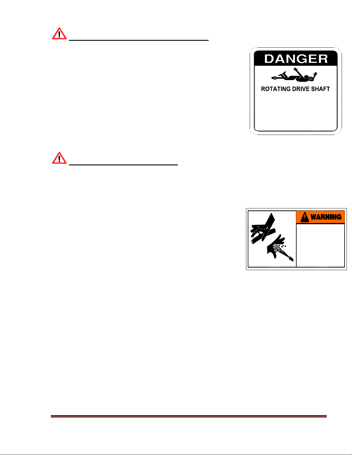
REPLACEMENT SAFETY DECALS; (cont.)
Figure E Figure F
DANGER; use only authorized WARNING; service and adjust
Part No. KM-02 Part No. W-100
Figure G Figure H
IMPORTANT; auger bolts must be kept IMPORTANT; keep area between
Part No. N/A Part No. N/A
Figure I Figure J
BE CAREFUL; keep all shield in place Danger; beware of moving parts
Part No. KM-10 Part No. KM-01
USE ONLY AUTHORIZED
KIRBY SHEAR PINS
KM-02
SERVICE AND ADJUSTMENT
OF HYDRAULIC SYSTEM
SHOULD ONLY BE PERFORMED
BY QUALIFIED PERSONNEL.
IMPROPER ADJUSTMENT COULD
CAUSE SERIOUS INJURY,
DAMAGE TO SYSTEM,
AND VOID WARRANTY.
OR MISSING BOLTS.
REPLACEMENT.
CHECK MONTHLY FOR LOOSE, DAMAGED
AUGER BOLTS MUST BE KEPT TIGHT!
USE ONLY KIRBY AUGER BOLTS FOR
8. MAKE CERTAIN EVERYONE IS CLEAR OF MACHINE BEFORE STARTING ENGINE
LUBRICATE, CLEAN OR UNCLOG MACHINES, UNLESS OTHERWISE SPECIFICALLY
7. USE FLASHING WARNING LIGHTS WHEN OPERATING ON HIGHWAYS EXCEPT
1. KEEP ALL SHIELDS IN PLACE.
WHEN PROHIBITED BY LAW.
OBSERVATION IS PROVIDED.
5. KEEP OFF EQUIPMENT UNLESS SEAT OR PLATFORM FOR OPERATION AND
4. KEEP HANDS, FEET AND CLOTHING AWAY FROM POWER DRIVEN PARTS.
3. WAIT FOR ALL MOVEMENT TO STOP BEFORE SERVICING THE MACHINE.
RECOMMENDED IN THE "OPERATORS MANUAL".
2. STOP ENGINE BEFORE LEAVING OPERATOR'S POSITION TO ADJUST,
6. KEEP ALL OTHERS OFF.
OR OPERATION.
KM 10
MOVING PARTS KEEP
ALL SHIELDS IN PLACE
BEWARE OF
KM 01
Page 17
VI-MMXII Page 17
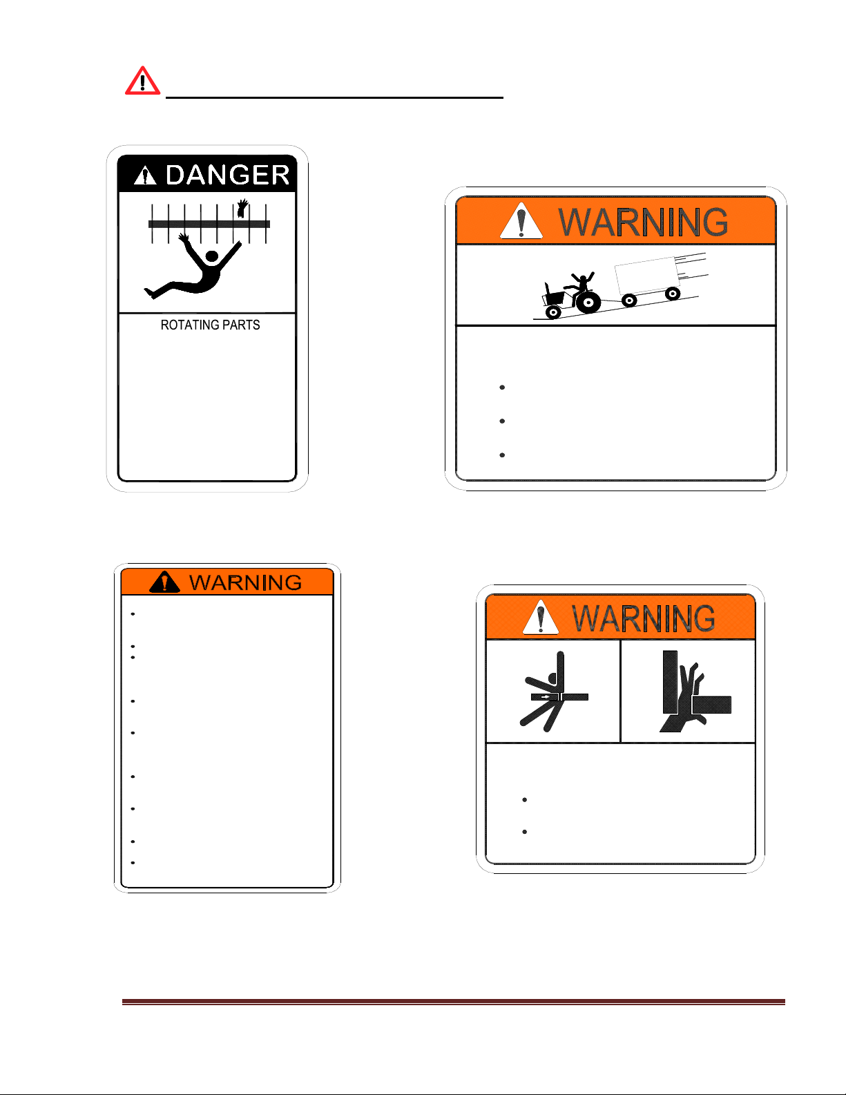
REPLACEMENT SAFETY DECALS; (cont.)
Figure K Figure L
DANGER; drive shaft DANGER; if you can read this
Part No. KM-07 Part No. KM-05
Figure K
DANGER; rotating auger
Part No. KM-03
Your best assurance against accidents is a careful and responsible operator. If there is
any portion of this manual or function you do not understand, contact your dealer or Kirby
Manufacturing.
DO NOT WORK ON
WITHOUT DISCONNECTING
POWER SOURCE
KM 07
IF YOU CAN READ
THIS, THE SHIELD
IS NOT IN PLACE
SHUT MACHINE OFF
REPLACE SHIELD
MOVING PARTS-
FAILURE TO HEED
CAN RESULT IN
DEATH
KM-05
ROTATING AUGER
HAVE SPOUT IN UP
POSITION WHEN MIXING
KEEP HANDS AWAY
FAILURE TO HEED
WILL RESUL IN
PERSONAL INJURY
OR DEATH
KM 03
Page 18

VI-MMXII Page 18
BEFORE OPERATION
Carefully study and understand this manual. Note: it is the responsibility of the owner to train all
current, new and future operators of the equipment. If assistance is needed, please contact Kirby
Manufacturing.
Do not wear loose-fitting clothing which may catch in moving parts.
Always wear protective clothing and substantial shoes.
Keep wheel lug nuts or bolts tightened to specified torque.
Assure that agricultural implement tires are inflated to the proper pressure.
Prior to operating the equipment, give the equipment a visual inspection for any loose bolts, worn
parts or cracked welds, and make necessary repairs. Follow the maintenance safety instructions
included in this manual.
Be sure that there are no tools lying on or in the mixer/feeder.
Do not use the unit until you are sure that the area is clear, especially of children and animals.
Always check inside of mixer prior to starting it up.
Because it is possible that this mixer/feeder may be used in dry areas or the presence of combustibles,
special precautions should be taken to prevent fires and firefighting equipment should be readily
available.
Don’t hurry the learning process or take the unit for granted. Ease into it and become familiar with
your new mixer/feeder.
Practice operation of your mixer/feeder and its attachments. Completely familiarize yourself and
other operators with its operation before using.
Securely attach to towing unit. Use a high strength, appropriately sized hitch pin with a mechanical
retainer.
Do not allow anyone to stand between the tongue or hitch and the towing vehicle when backing up
to the mixer/feeder.
Page 19

VI-MMXII Page 19
DURING OPERATION
Beware of bystanders, particularly children! Always look around to make sure that it is safe to
start the engine of the towing vehicle or move the unit. This is particularly important with higher
noise levels and quiet cabs, as you may not hear people shouting. NO PASSENGERS ALLOWED
- Do not carry passengers anywhere on, or in, the tractor or equipment, except as required for
operation.
Keep hands and clothing clear of moving parts. Do not clean, lubricate or adjust your mixer/feeder
while it is running.
Be especially observant of the operating area and terrain - watch for holes, rocks or other hidden
hazards. Always inspect the area prior to operation.
Do not operate on steep slopes as overturn may result. Operate up and down (not across)
intermediate slopes. Avoid sudden starts and stops. Pick the most level possible route when
transporting across fields. Avoid the edges of ditches or gullies and steep hillsides. Be extra careful
when working on inclines.
Periodically clear the equipment of hay, feed, twine or other materials to prevent buildup of dry
combustible materials.
Maneuver the tractor or towing vehicle at safe speeds. Avoid overhead wires or other obstacles.
Contact with overhead lines could cause serious injury or death. Allow for unit length when making
turns.
Do not walk or work under raised components or attachments unless securely positioned and
blocked.
Keep all bystanders, pets and livestock clear of the work area.
Operate the towing vehicle from the operator’s seat only. Never stand alongside of the unit with
engine running. Never attempt to start engine and/or operate machine while standing alongside of
unit.
Never leave a running mixer/feeder unattended.
As a precaution, always check the hardware on mixer/feeder prior to operating the equipment.
Correct all problems. Follow the maintenance safety procedures.
FOLLOWING OPERATION
Following operation, or when unhitching, stop the tractor or towing vehicle, set the brakes, disengage
the PTO and all power drives, shut off the engine and remove the ignition keys.
Store the unit in an area away from high traffic areas.
Page 20

VI-MMXII Page 20
To prevent damage to the equipment and injury to livestock, do not park equipment where it will
be exposed to livestock for long periods of time.
Do not permit children to play on or around the stored unit.
Make sure parked machine is on a hard, level surface and engage all safety devices.
Wheel chocks should be used to prevent unit from rolling.
HIGHWAY AND TRANSPORT OPERATIONS
Keep the brake pedals latched together at all times. Never use independent braking with machine in
tow as loss of control and/or upset of unit can result.
Always drive at a safe speed relative to local conditions and ensure that your speed is low enough
for an emergency stop to be safe and secure. Keep speed to a minimum.
Reduce speed prior to turns to avoid the risk of overturning.
Avoid sudden uphill turns on steep slopes.
Always keep the tractor or towing vehicle in gear to provide engine braking when going downhill.
Do not coast.
Comply with state and local laws governing highway safety and movement of farm machinery on
public roads.
Use approved accessory lighting, flags and necessary warning devices to protect operators of other
vehicles on the highway during daylight and nighttime transport. The use of flashing amber lights is
acceptable in most localities. However, some localities prohibit their use. Local laws should be
checked for all highway lighting and marking requirements.
When driving the tractor and mixer/feeder on the road or highway under 20 MPH (40 KPH) at night
or during the day, use flashing amber warning lights and a slow-moving vehicle (SMV)
identification emblem.
Plan your route to avoid heavy traffic. Be a safe courteous driver. Always yield to oncoming traffic
in all situations, including narrow bridges, intersections, etc.
Be observant of bridge loading ratings. Do not cross bridges rated lower than the gross weight at
which you are operating. Watch for obstructions overhead and to the side while transporting.
Always operate mixer/feeder in a position to provide maximum visibility at all times.
Make allowances for increased length and weight of the mixer/feeder when making turns, stopping
the unit, etc.
Page 21

VI-MMXII Page 21
PERFORMING MAINTENANCE
Good maintenance is your responsibility. Poor maintenance is an invitation to trouble.
Make sure there is plenty of ventilation. Never operate the engine of the towing vehicle in a closed
building. The exhaust fumes may cause asphyxiation.
Before working on the mixer/feeder, stop the towing vehicle, set the brakes, and disengage the PTO
and all power drives, shut off the engine and remove the ignition keys.
Be certain all moving parts on attachments have come to a complete stop before attempting to
perform maintenance.
Always use a safety support and block the wheels. Never use a jack to support the machine.
Always use the proper tools or equipment for the job at hand.
Use extreme caution when making adjustments.
Never use your hands to locate hydraulic leaks on attachments. Use a small piece of cardboard or
wood. Hydraulic fluid escaping under pressure can penetrate the skin.
When disconnecting hydraulic lines, shut off hydraulic supply and relieve all hydraulic pressure.
Openings in the skin and minor cuts are susceptible to infection from hydraulic fluid. If injured by
escaping hydraulic fluid, see a doctor at once. Gangrene can result. Without immediate treatment,
serious infection and reactions can occur.
Replace all shields and guards after servicing and before moving. After servicing, be sure all tools,
parts and service equipment are removed.
Do not allow grease or oil to build up on any step or platform.
Never replace hex bolts with less than grade five (5) bolts unless otherwise specified.
Where replacement parts are necessary for periodic maintenance and servicing, genuine factory
replacement parts must be used to restore your equipment to original specifications.
Kirby Manufacturing will not be responsible for damages caused using unapproved parts and/or
accessories. This will void your warranty.
If equipment has been altered in any way from original design, Kirby Manufacturing does not accept
any liability for injury or warranty.
A fire extinguisher and first aid kit should be kept readily accessible while performing maintenance
on this mixer/feeder.
Page 22

VI-MMXII Page 22
2.0 MIXER STRUCTURE AND TRAILER
2.1 Observe for cracks in metal and welds in mixer chamber, trailer frame, and axle assembly and
around discharge door and chute. Re-weld as necessary.
2.2 Observe trailer hitch for
(I) Cracked welds. Re-weld as necessary.
(II) Bent or worn. Replace or repair as necessary.
2.3 Observe that all bolts are in place and that all sets crews are properly seated. Replace or
tighten as required.
2.4 Observe for hydraulic oil leaks. Repair any leaks.
2.5 Trailer mount only. Observe trailer tires:
(I) For cuts or punctures in tires.
(II) Check for proper inflation using pressure gauge.
(fill to the maximum pressure rating shown on side of tire)
2.6 Observe wheel hubs and bearings.
(I) Check for oil seal leaks. Replace if seal leaks.
(II) Check wheel hubs for proper bearing tightness. Tighten as required.
(III) Observe oil level in cap, oil must be level with bottom of filler hole. Fill with proper
lubricant to over flow.
3.0 MAIN AUGERS, SHAFTS, AND BEARINGS
CAUTION! THE MIXER SHALL NOT BE IN OPERATION FOR THE FOLLOWING:
3.1 Observe auger flighting, in mixing chamber
(I) Bent, deformed, or worn to less than 25% of new thickness.
(II) Replace flighting as necessary.
(III) Check blades on mixer replace when worn
3.1 Observe mixing chamber, sides and ends.
(I) Walls and ends should be straight, not bulging in appearance. This condition can result
from over loading or foreign objects present in ration.
(II) Look for signs of excessive wear
3.2 Observe tractor drive line and mixer drive line for bent shafts.
(I) Ensure all shields are in place and operational (sliding without restrictions)
Page 23

VI-MMXII Page 23
4.0 SPROCKET AND CHAINS, (CROSSFEED)
4.1 Observe chain for properly seating on sprocket. Use caution while observing mixer while in
operation. Look for chain jerking motion, when chain wraps around sprocket. Jerking motion
may indicate:
(I) Misalignment of chain and sprocket. Realign
(II) Worn or loose chain. Replace worn chain.
(III) Loose chain idlers. Reposition and tighten idler.
(IV) Bent shafts. Replace with new shafts.
4.2 Observe sprocket tooth wear pattern.
(I) Tooth worn on sides indicates misalignment. Realign sprocket.
(II) Tooth worn to a sharp point indicates loose or worn chain. Adjust sprockets
(III) Tooth worn to cup at base indicates excessive load on chain. Adjust sprockets
4.3 Observe sprockets for the following.
(I) Main key sheared or shearing. Replace key.
(II) Main set screws loose or missing. Tighten or replace.
(III) Movement or signs of movement of sprockets on shaft. Tighten or replace.
(IV) Alignment - Using a straight bar, insure that both sprocket faces are in full contact with
the edge of the bar.
5.0 GEAR BOXES
5.1 Main planetary drive.
(I) Observe oil level of gearbox reservoirs, use clear view tube on oil reservoir.
(II) Observe for any over-fill oil coming out of the gearbox oil reservoir tank.
5.2 Two speed gearboxes
(I) Observe shaft seals for leaks. Replace seals.
(II) Check for loose bolts that secure gearbox to mounting bracket.
(III) Check for misalignment to other components: U-joints. Shear hub
(IV) Check input shaft, movement indicates worn bearings. Replace.
(V) Check out put shaft for movement, realign and tighten set screws.
(VI) Check to see that the oil is level with the filler plug located on the side of this gearbox.
Fill to overflow.
(VII) Check tightness of gearbox mounting bolts.
Check shifting lever and cables. Adjust cable for optimum engagement in both high and low speed
selections on gearbox.
5.3 For regular service, refer to the “Preventive Maintenance and Lubrication Schedule” located
in Section 8 of the manual.
Page 24

VI-MMXII Page 24
6.0 DRIVELINES AND POWER TAKEOFFS
6.1 Tractor PTO driveline
(I) Shields must be secured by locking devices
(II) Shields must slide freely.
(III) Observe shields for damage.
(IV) Driveline shafts must slide freely, binding may cause false readings on the scale
system. Lubricate all shaft splines.
(V) U-joints cross & yoke must fit tight in the bearing cups and have zerk fittings for
lubrication.
6.2 Truck mounted mixer PTO’s
(I) Observe for oil leaking around PTO shaft seal. Replace seal.
(II) Check PTO for loose bolts holding PTO to transmission or engine crank shaft. Tighten
bolts.
(III) Check U-joints, bearings, yokes, and set bolts. Replace worn parts and tighten all
bolts.
(IV) Lubricate driveline “U” joints as per the “Preventive Maintenance and Lubrication
Schedule”
6.3 Mixer drive line.
(I) Check for loose or missing set screws or lock collars in pillow block bearings and
driveline yokes. Tighten or replace lock collars set screws.
(II) Check for loose or missing bolts in pillow block bearings. Tighten or replace.
(III) Observe driveline under operation. CAUTION STAY CLEAR OF ALL MOVING
PARTS, DO NOT WEAR LOOSE CLOTHING!!
(IV) Check for vibration, worn bearings, bad U-joint bearings, or bent shaft. Replace worn
or damaged parts.
(V) Observe for linear movement through bearings, this is indicated by unpainted surface of
shaft exposed on each side of bearing locking collar. Realign and tighten loose locking
bolts.
(VI) Observe for loose set screws or PTO shaft not slipping in sleeve, causing end thrust load
on the bearings.
(VII) Check for bent shaft. Replace and grease as per lubrication schedule.
Page 25

VI-MMXII Page 25
7.0 MAIN HYDRAULIC SYSTEM
STATIONARY AND TRUCK MOUNTED VERTICAL MIXERS
QUICK REFERENCE INFORMATION
Thank you for your investment in a Kirby hydraulic driven mixer. With proper care and service you
can extend the life of the hydraulic system.
Your system is equipped with two (2) Sauer-Sundstrand Series 90 axial piston pumps, two (2)
Parker/VOAC variable displacement hydraulic motors Series V14 and two (2) Fairfield planetary
gearboxes.
In order to ensure hydraulic system efficiency only fresh, clean oil should be added to the hydraulic
tank. ALL hydraulic oil that is added to the system must be filtered through a 10-micron filter to
ensure oil cleanliness. If any lines are damaged, unfastened or replaced, extreme care must be
taken to prevent dirt from entering the hydraulic system. All open lines should be capped. Filter
indicator should be checked regularly and the filters should be replaced if indicated, or as hours of
use require. When replacing the filters always replace O-ring on canister.
Kirby Manufacturing recommends that only authorized Kirby filters be used for replacement. The
filters used must be at least a 10-micron filter. Oil specifications are Pennzoil AW68.
It is critical that proper maintenance and filter changes be made on a regular basis. Warranty is based
on the regular maintenance of your system. Not changing your oil and filters properly and within the
time frame given WILL VOID YOUR WARRANTY. All filters should be kept clean and free of
foreign contaminants when replacing to avoid oil contamination.
All hydraulic filters and all planetary gearbox oil should be changed after the first initial 50 hours
of use. Thereafter, all hydraulic filters should be changed every 500 hours. Use the reservoir filter
gauges, located on the top of the hydraulic fluid reservoir, to help determine when the next filter
change is necessary.
The first oil change on the planetary gearboxes should occur after 50 hours of use. Thereafter, oil
changes should occur every 1,000 hours.
Page 26

VI-MMXII Page 26
Procedure for changing the oil in the planetary gearbox:
1. First, run unit to warm oil in gear boxes
2. To drain the planetary gearbox oil, place a bucket under the planetary gearbox to catch the
used oil, detach the bottom hose (the other end of this hose goes to the bottom of gear oil
supply reservoir) from the bottom of the gearbox. Let the oil from the gearbox and the bottom
hose drain into the bucket.
3. Take the plug out of the end of the gearbox’s top hose. This is the other hose that hangs down
from the side of the planetary gearbox. Place an air hose to the end of the top hose. Using
compressed air (no more than 20 psi.) gently force the oil out the bottom of the gearbox.
Note: Excessive air pressure could damage the top output seal of the gearbox.
4. To fill the gearbox, re-attach the bottom hose to the bottom of the gearbox.
5. Add (warm) oil through the reservoir fill cap, located on the reservoir, until oil comes out of
the end of the top hose.
6. Re-place plug in top hose and (if needed) add oil until oil reaches fill line on sight glass and
check periodically to ensure that the level is correct.
Recommended oil for this gearbox is PENNZOIL MULTI-PURPOSE GEARLUBE 4140,
GRADE SAE-85W-140 with “EP” (Extreme Pressure) additive (for other oil choices see the
additional specification listed below)
If you have opted for the “Extended Warranty”, you will be provided with oil sampling kits. You
should use these kits when pulling oil samples on your equipment. It is crucial that oil samples be
pulled in accordance to the provided schedule. YOUR WARRANTY WILL BE VOID IF ONE
OIL SAMPLING TEST IS MISSED.
Once your oil sample is sent in and analyzed, the information will then be sent back to you. This
information will provide you with valuable information on the condition and maintenance of your
hydraulic system. It is your (the customer’s) responsibility to maintain the oil cleanliness to the
specifications provided. OIL SAMPLING SHOULD BE DONE WITH EVERY OIL FILTER
CHANGE, INCLUDING THE FIRST 50 HOURS.
After you receive your fluid analysis report, you should check it to ensure that it meets or exceeds
the specifications stated. For hydraulic oil the “cleanliness code” specifications are as follow: Your
hydraulic oil should be in the 18/16/13 range. Any sampling that is lower than this is good; any
sampling that is higher is an indication that your oil is not clean and thus will reduce the life
expectancy of your system. You must immediately change your hydraulic filters and oil. Then run
the unit for 50 hours and take another sample.
ISO CODE MEANING
18/16/13 = # of particles
Particles > 2 microns Particles > 15microns
Particles > 5 microns
Page 27

VI-MMXII Page 27
If you have opted for the “Extended Warranty”, you will receive all the necessary oil sampling
kits when you receive your equipment. It is the customer’s responsibility to pull the oil samples
and send them in for analysis. All mail charges will be paid by the customer.
At this time, we suggest you buy your next set of change of filters. It will require two (2) intank element part # 7954, two (2) charge pump filters # 7956, and two (2) small breather filters
part # 7953 B (located on the side of the filler cap near the top of the hydraulic oil reservoir).
We recommend that you NEVER use paper element filters. Kirby offers a high efficiency, and
high capacity Microglass III type.
Oil temperature, cooling system and low fluid volume shut-down
Your unit is equipped with a hydraulic oil temperature readout (optional read-out) and hydraulic oil
cooling system.
Normal operating temperature range of your system depends on ambient temperature and duty cycle.
The range should vary between 150 and 180 degrees Fahrenheit.
An automatic hydraulic shut-off for the system is set at 190 degrees Fahrenheit. If the hydraulic oil
reaches the 190-degrees mark, the hydraulic system will automatically shut down.
You will still be able to drive your truck (truck mounted models), but the system will not come back
on until the oil cools down. If this failure occurs and you are unable to find the cause, call Kirby
Mfg. Inc 209-723-0778 for further assistance.
Your system has a hydraulic oil cooling system equipped with fan(s), which automatically will turn
on when the oil temperature reaches 120 degrees. The radiator for this system should be cleaned on
a daily basis. NOTE: be careful not to damage cooling fins on radiator when using compressed air
to blow out radiator. You should periodically physically check the fans to ensure they are working
when the hydraulic fluid temperature is above 120 degrees. DO NOT use water for cleaning the
hydraulic cooler.
Your unit is also equipped with a low volume hydraulic sensor in the hydraulic fluid reservoir. If for
any reason there is a loss of hydraulic fluid in the system the unit will automatically shut down. For
truck mounted units with front mounted pumps, the truck engine must not be started. SEVERE
DAMAGE will occur to the hydraulic system if you run the truck engine after the hydraulic
system has automatically shut down.
A check of the system should be made to determine the cause of the low volume shut-down. If for
whatever reason, your unit is not equipped with the “automatic shut-down” feature and you have a
major loss of hydraulic fluid in the system, you must shut down the truck engine immediately or
the hydraulic system will be severely damaged.
Page 28

VI-MMXII Page 28
GENERAL CHECK LIST
7.1 Observe all fittings, pipes, tubes, and hoses for leakage. Tighten as needed.
7.2 Observe oil level in main tank. On truck mount or stationary units the dipstick capacity allowed
is 95 liters. (25 gallons)
7.3 On tractors, the maximum pump capacity required to operate the mixer is 53 liters per minute
(14 gpm) @ 2200 P.S.I.. The minimum pump capacity required to operate the mixer is 46 liters
per minute (12 gpm) @ 2200 P.S.I..
7.4 Manifold block specification is 53 liters per minute (14 gpm) @ 3000 P.S.I. Caution: do not
exceed these limits.
7.5 Manifold relief valve is factory set @ 2200 P.S.I. for maximum safety to the system.
7.6 Manifold needle valve controls the speed at which the door opens. It may be adjusted as needed.
7.7 Discharge conveyor motor specification, maximum 57 liters per minute (15 gpm) @ 1700 P.S.I.
7.8 Discharge conveyor motor under normal operation requires a minimum of 46 liters per minute
(12 gpm) to a maximum of 53 liters per minute (14 gpm) to provide adequate unload speed. The
speed is controlled through the crossfeed flow control valve located on the mixer.
7.9 Stalling of the discharge conveyor motor may be caused by the loss of oil pressure (P.S.I.) to the
motor, due to incorrect adjustment of relief valve, or worn pump/ motor.
7.10 Slow speed of discharge conveyor motor may be caused by the loss of oil flow from the pump
source to the motor, due to worn pump or restricted flow in the tractor hydraulic system/hydraulic
hoses.
7.11 Truck mount and Stationary mixers have 12-volt solenoid valves to operate conveyor motor and
hydraulic door. Solenoids may be shifted manually by inserting 1/8” shaft into the hole at each
end of solenoid. This method will determine if the 12-volt power supply or the switches are
defective. This method can also be used to determine if the solenoid is struck or otherwise
defective resulting in a problem with the operation of the discharge.
7.12 For service see preventive maintenance and lubrication schedule in Section 8.
Page 29

VI-MMXII Page 29
8.0 LUBRICATION AND PREVENTATIVE MAINTENANCE
8.1 Main auger bearings.
(I) Each planetary gearbox (located under the augers) has a top bearing that need lubrication.
Lubricate these bearings from the grease bank zerks located on the sides of the mixer.
Lubricate these bearings every 140 hours!
(II) Check to see that all grease lines and grease zerks are in place and in good working order,
not plugged, loose or kinked.
(III) Pump grease using a standard hand pump one (1) pump for each bearing. Always be sure
the machine is operating and the bearings are rotating to ensure that they take grease.
CAUTION: DO NOT OVER GREASE. THIS SHOULD BE A TWO MAN
OPERATION. ENSURE ALL SAFETY PRECAUTIONS ARE TAKEN.
1.BEWARE OF ALL MOVING PARTS.
2.DO NOT WEAR LOOSE FITTING CLOTHING
3.BEWARE OF THE PTO
8.2 Discharge conveyor bearings.
(I) There are two take-up bearings on the discharge end of the crossfeed conveyor
(II) There are also two flange bearings on the opposite side of the discharge
(III) Both have grease zerk that need greasing once a week
(IV) Check that all grease lines and grease zerks are in place and in good working order, not
plugged, loose or kinked.
(V) Pump grease using a standard hand pump grease gun 3 to 4 times for each bearing.
Always be sure the machine is operating and the bearings are rotating to ensure that they
take grease. Caution: Excessive grease will blow out the bearing seals. DO NOT
OVER GREASE. THIS SHOULD BE A TWO MAN OPERATION. ENSURE ALL
SAFETY PRECAUTIONS ARE TAKEN
1.BEWARE OF ALL MOVING PARTS.
2.DO NOT WEAR LOOSE CLOTHING
3.BEWARE OF THE PTO
8.3 Power takeoff. U-joints and slip sleeves.
(I) Follow safety procedures. DO NOT service while the tractor is running or the PTO is
engaged or in motion.
(II) Key should be removed from tractor or truck before attempting to grease the PTO, U-
Joints & Yokes.
(III) U-joints (crosses and yokes) must be tight in the bearing cups.
(II) Bearings are greased through zerk grease fittings. Pump grease using a standard hand
pump grease gun until you observe grease coming out of ALL FOUR CUPS OF THE
U-JOINT bearings.
8.4 Check all safety shields and ensure that all are in place.
Page 30

VI-MMXII Page 30
LUBRICATION SCHEDULE
(Unless stated differently in this manual use the below chart as a general lubrication
schedule/guideline when performing preventative maintenance on your equipment)
PM
SERVICE
1
st
50
Hours
Every
140
Hours
Every
200
Hours
Every
500
Hours
Every
1000
Hours
Every 3
Months
Every 6
Months
Every
12
Months
Change oil in
All gearboxes
X X
(2)
X
(2)
(1)
Pull gearbox oil
sample for analysis
X X
(2)
X
(2)
Change hyd. Oil &
Send in samples
X
(1)
Pull hydraulic oil
sample for analysis
X
X
(3)
X
(3)
Grease top
Planetary Bearing
X
Change hydraulic
oil filters
X
X
(3)
X
(3)
Grease all
Mixer bearings
X
Grease PTO, Drive
Line & Slip Sleeve
X
Check out
Mixer
X
Repack
Wheel bearings
X
NOTE: For a more detailed Preventative Maintenance (PM) Schedule refer to the
“Maintenance Schedule Checklist” located at the end of this chapter.
(1)
If you have opted for the three (3) year “Extended Warranty Policy” on all major components, it
is required that you sample oils on the frequencies stated in the “Extended Warranty Policy” section
of this manual. This is necessary to not void the “Extended Warranty Policy” (see the “warranty
section” of this manual for more details). Even if you have not chosen the “Extended Warranty
Policy”, it is “best practices” to perform regular oils sampling and analysis for proper maintenance
of the equipment.
(2)
1,000hrs or 6 months whichever comes first.
(3)
500hrs or 3 months whichever comes first.
Page 31

VI-MMXII Page 31
LUBRICANT TYPES:
COMPONENTS
LUBRICATE
NAME
LUBRICATE
TYPE
LUBRICATE
GRADE
PLANETARY
GEARBOX OIL
(IMPORTANT!!)
SEE CHOICES
A: 1,2, or 3
BELOW
SEE CHOICES
A: 1,2, or 3
BELOW
SEE CHOICES
A: 1,2, or 3
BELOW
PLANETARY
GEARBOX TOP
BEARING GREASE
SEE CHOICE
B:
BELOW
SEE CHOICE
B:
BELOW
SEE CHOICE
B:
BELOW
BEARINGS AND
DRIVE LINE YOKES
GREASE
PENNZOIL
AW
NLGI #2
TWO SPEED
SHIFTABLE
GEARBOX OIL
SEE CHOICES
A: 1,2, or 3
BELOW
SEE CHOICES
A: 1,2, or 3
BELOW
SEE CHOICES
A: 1,2, or 3
BELOW
HYDRAULIC
SYSTEM OIL
(TRUCK ONLY)
PENNZOIL
AW
68
HYDRAULIC MOTOR
SPLINES
(TRUCK ONLY)
SEE CHOICE
C:
BELOW
SEE CHOICE
C:
BELOW
SEE CHOICE
C:
BELOW
A. PLANETARY GEARBOX OIL CHOICES:
(ALSO, USE THIS GEAR OIL IN RIGHT ANGLE, TEE AND
TWO SPEED GEARBOXES)
1.) Mobil ........Mobilube SHC 75W-90
2.) Chevron.....Chevron RPM Synthetic Gear Lubricant SAE 75W-90
3.) Texaco......Texaco Syn-Star GL 75W-90
4.) Texaco …Texaco multigear EP SAE 85W-140
* IMPORTANT !!: All gearbox oils MUST have an EP (“Extreme Pressure”) additive.
B. PLANETARY GEARBOX TOP BEARING GREASE:
** Use an NLGI Grade 2 grease with an EP (“Extreme Pressure”) additive.
C. COUPLING GREASE:
Texaco Coupling grease, CPS number 221912
Use when mating male and female splined shafts and coupling to reduce “fretting” of spline
material.
Areas of application:
- between PTO spline connections
- between hydraulic motor splines and planetary input splines
PROCEDURE FOR SAMPLING AND CHANGING OILS:
The following information pertains to changing and sampling the oils in both the gearboxes and the
hydraulic circuit (trucks only) on the mixer.
Page 32

VI-MMXII Page 32
Note: Always make sure to change and sample oil immediately after the equipment has been in
operation. This will ensure that the oils are warm which will allow them to flow more freely when
being drained. Also, this will ensure that any particles that are in the oil will be in suspension while
pulling an oil sample. ALWAYS PARK EQUIPMENT ON A LEVEL SURFACE WHEN
CHANGING OIL AND CHECKING OIL LEVELS.
I. GEARBOXES:
A. Planetary Gearboxes, (truck and trailer):
Draining gearbox:
1. Locate gearbox oil reservoir on outside of unit.
2. Wipe hose end and fitting clean below oil
reservoir.
3. Place drain pan on the ground under oil
reservoir.
4. Remove cap at end of the high-level fill hose
hanging down beside gearbox.
5. Remove hose from bottom of reservoir and
drain, (this hose is used for draining and
filling).
6. While oil is draining out, 30 seconds, then
capture a sample in the cleaning sample bottle.
7. Cap sampling bottle and completely fill out information sheet.
Filling gearbox:
1. Fill gearbox via the reservoir hose. Note: Since
gear oil is thick and doesn’t flow freely, an oil
dispensing pump system is needed when refilling oil. Dispensing pump pressure should
never exceed 10 psi, so seals are not damaged.
2. IMPORTANT: gearbox is full only when oil
starts to flow from the “high level” fill hose, do
not run mixer until oil is seen coming out of
“high level” fill hose.
3. At this point, stop adding oil to the reservoir and
observe “high level” fill hose.
4. When the excess oil has stop flowing from the “high level” fill hose SECURELY replace
cap.
5. Reconnect hose to bottom of reservoir.
6. Check oil level on gearbox reservoir, (the oil level in the reservoir should be located at
approximately the middle of the reservoir, add oil if needed).
7. Run equipment, recheck oil levels and check for leaks.
8. You have now successfully completed the oil changing process.
9. IMPORTANT: Recheck oil levels daily in reservoirs over the next week period to ensure
proper oil levels are maintained.
cap @ end of “high
level” fill hose
Gearbox Reservoir
Reservoir
Fill level
planetary
gearbox
Page 33

VI-MMXII Page 33
B. Two Speed Manual Shift Gearbox, (optional on trailer only):
Draining gearbox:
Step
1. Locate drain plug on bottom of gearbox
2. Wipe area clean around drain plug
3. Place drain pan under gearbox drain plug
4. Remove drain plug from bottom of gearbox.
5. While oil is draining out capture sample in clean
sampling bottle
6. Cap sampling bottle and completely fill-out
information sheet
7. SECURELY replace plug when last of oil has
drained from gearbox
C. Two Speed Manual Shift Gearbox, (optional on trailer only):
Filling gearbox:
Step
1. Remove fill plug on side of gear box, (this plug is in
the middle of the gearbox).
2. Fill gearbox through the fill plug hole, (Note:
warm oil will flow quicker).
3. Continue filling until oil starts to flow from fill
hole.
4. Replace plug and wipe excess oil from area.
5. Run equipment and recheck oil levels and check for
leaks.
Drain plug
Fill plug
Page 34

VI-MMXII Page 34
II. HYDRAULIC SYSTEM, (truck mount only):
BOTTLE SAMPLING PROCEDURE :
1.
A representative oil sample should be
drawn directly after the shut down before
the filter.
2.
Check whether the thread of the pump (1)
is clean, if not please use a lint- free cloth.
3.
The sample can be taken quickly through
the dip-stick opening. Please estimate the
required tube length (use the dip-stick) and
cut the end to an angle of approximately
45°.
4.
Release the aluminum knurled screw (2) on
the pump (1) so that you can insert the tube
through the whole of the knurled screw.
5.
Tighten the knurled screw (2). So the tube
(6) will be fixed to the seal (3). The system
is sealed now.
6.
Screw the open sampling bottle (5) on the
"VAMPIRE" pump (1).
7.
Carefully clean the sample taking tube to
avoid sample contamination.
8.
Insert the end of the sampling tube through
the inlet into the oil. The tube should not
touch the bottom of the oil tank or oil pan.
9.
Always hold the sampling bottle in a
vertical position (see picture).
10.
Start pumping the oil into the bottle. Stop pumping early enough to prevent
contamination of the pump by overflowing the bottle. Leave 1 cm of the
bottle unfilled to allow the oil being shaken.
11.
Loose the knurled screw to release the vacuum and remove the tube from
the pump.
12.
Unscrew the bottle and close it with the cap (4).
Page 35

VI-MMXII Page 35
Maintenance Schedule; (for trailer mounted vertical mixer)
Maintenance Schedule
equipment: vertical mixer (trailer mount)
frequency:
100 hours, (approximately 1 week intervals); (UNLESS STATED OTHERWISE BELOW)
MAJOR AREAS
1. CUSTOMER INFO.
minor areas item description check-off
follow-up
required
(y/n)
general 1 speak with equipment operators
2 speak with maintenance technicians
2. HYDRAULIC SYSTEM
minor areas item description check-off
follow-up
required
(y/n)
general 1 check for leaks; (hoses, fittings, seals, etc)
2 check oil levels, fill if needed (after pulling samples)
3
check pressure bypass settings & record (where applicable)
4 check for worn hoses & loose fittings
5 start mixer and check general operating parameters
6 check operations of hydraulic cylinders & motors
3. MECHANICAL SYSTEM
minor areas item description check-off
follow-up
required
(y/n)
general 1
are all guards in place, (notify customer if not)
2 start mixer and listen for unusual noises
3 look for worn/broken parts
4 lubricate all grease zert fittings and/or points of lubrication
5 check drive line shear pin
planetary gearbox 1
check oil levels (daily), fill if needed; (pull oil sample and
change oil every 1000 hrs, 1st oil change at 50 hrs)
2 pull and identify oil samples, (send out for testing)
3 is oil clear and free of contamination
4 grease top bearing every 140 hours
90 degree &
"Tee" gearbox
1
check oil levels, fill if needed; (pull oil sample and
change oil every 1000 hrs, 1st oil change at 50 hrs)
2 grease bearings; (2 locations per gear box)
augers 1 check backlash & tightness, (rotate auger back & forth)
2 check for damage & wear on flighting
3 check knives for wear & tightness
main tub 1 check wear on inside of tub, (floor & walls)
2 check stainless seams and wear (where applicable)
3 check door operations, adjust if needed & lubricate
Page 36

VI-MMXII Page 36
Maintenance Schedule; (for trailer mounted vertical mixer), con’t
NOTE: It is suggested to make copies of this “Maintenance Schedule” form to assist with
performing routine maintenance inspection of the equipment. This will also serve as a
retention record of all safety and maintenance inspections.
4 check hay brake operations
cross conveyor 1 check for wear on chain assembly
2 check for wear on flooring
3 check drive system
4 check conveyor take-ups and adjust if needed
5 check operations of cross conveyor slide
two speed gear box
1 check yokes for tightness, (check set screws)
2 check oil levels, fill if needed (after pulling sample)
3 check shift pressures & record (where applicable)
4 check shift linkage adjustment & tighten (where applicable)
5 check tightness of gearbox mounting bolts
PTO 1 check and grease shaft, (check set screws & locking collar)
4. WEIGH SYSTEM
minor areas item description check-off
follow-up
required
(y/n)
general 1 check operations of scales
2 check for rotation of load ceils
3 check for damaged wiring
. 4 check and clean load ceil mounting "V" brackets
5 check local support/truck frames for cracks
6 check to see if load cells are loose (i.e. not carrying the load)
5. TEST MIXER'S OPERATIONS
minor areas item description check-off
follow-up
required
(y/n)
general 1 "run-in" mixer for a period of time (15min+) to insure smooth
operations. Walk around equipment and inspect all
components for smooth operations
ADDITIONAL NOTES AND COMMENTS:
AFTER SERVICE IS COMPLETED; WRITE SERVICED DATE WITH YOUR INITIALS ON A STICKER AND
PLACE ON UNIT NEXT TO SERIAL NUMBER ID PLATE.
Page 37

VI-MMXII Page 37
Maintenance Schedule; (for truck mounted vertical mixer)
Maintenance Schedule
equipment: vertical mixer (truck mount)
frequency:
100 hours; approximately 1 week intervals; (UNLESS STATED OTHERWISE BELOW)
Customer ___________________________ Location
__________________
Date service performed Hours on truck
___________________________ Hours on unit
__________________
Equipment ser. no. ___________________________ Service technician
__________________
MAJOR AREAS
1. CUSTOMER INFO.
minor areas item description check-off
follow-up
required
(y/n)
general 1 speak with equipment operators
2 speak with maintenance technicians
2. HYDRAULIC SYSTEM
minor areas item description check-off
follow-up
required
(y/n)
general 1 check for leaks; (hoses, fittings, seals, etc)
2
pull and identify oil samples, (every 500 hrs )
3 check oil levels, fill if needed
4
change all oil filters, (every 500 hrs )
5
change hydraulic oil, (every 4000 hrs.; approx. 1 year)
6
check pressure bypass (relief) settings & record
7 check for worn hoses
8 start mixer and listen for unusual noises
9 start mixer and check general operating parameters
10
check driveline to pumps; (lubricate yokes every 8 hrs)
( a needle lube gun fitting is needed)
11 check operations of hydraulic actuators
12 check and record pressures on pump (w/ load & w/o load)
13 check and record pressures on motor (w/ load & w/o load)
14
clean heat exchanger (radiator) on hydraulic system (daily)
3. MECHANICAL SYSTEM
minor areas item description check-off
follow-up
required
(y/n)
general 1 are all guards in place, (notify customer if not)
2 start mixer and listen for unusual noises
3 look for worn/broken parts
4 lubricate all grease zert fittings and/or points of lubrication
planetary gearbox 1
check oil levels (daily), fill if needed; (pull oil sample and
change oil every 1000 hrs, 1st oil change at 50 hrs)
2 if applicable, identify oil samples; (send out for testing)
3 is oil clear
4 grease top bearing every 140 hours
Page 38

VI-MMXII Page 38
Maintenance Schedule; (for truck mounted vertical mixer), con’t
NOTE: It is suggested to make copies of this “Maintenance Schedule” form to assist with
performing routine maintenance inspection of the equipment. This will also serve as a
retention record of all safety and maintenance inspections.
augers 1 check backlash & tightness, (rotate auger back & forth)
3 check for damage & wear on flighting
4 check knives for wear & tightness
main tub 1 check wear on inside of tub, (floor & walls)
2 check stainless seams and wear
3 check door operations, adjust if needed & lubricate
4 check hay brake operations
cross conveyor 1 check for wear on chain assembly
2 check for wear on flooring
3 check drive system
4 check conveyor take-ups and adjust if needed
5 check operations of cross conveyor slide
4. WEIGH SYSTEM
(mechanical)
minor areas item description check-off
follow-up
required
(y/n)
1 check operations of scales
2 check for rotation of load cells and tighten locking screw
3 check for damaged wiring
. 4 check and clean load cell mounting "V" brackets
5 check local support/truck frames for cracks
6 make sure 7/8" bolt in load mounting bracket is loose
ADDITIONAL NOTES AND COMMENTS:
AFTER SERVICE IS COMPLETED; WRITE SERVICED DATE WITH YOUR INITIALS ON A STICKER
AND PLACE STICKER ON UNIT NEXT TO SERIAL NUMBER ID PLATE.
NOTE: The above maintenance program covers the operation of the mixer and does not include truck maintenance checks
or safety checks, (other than guarding).
Page 39

VI-MMXII Page 39
9.0 ELECTRONIC SCALES AND LOADCELLS
CAUTION: DO NOT WELD ON EQUIPMENT. Scales must be disconnected from power
source and/or battery before welding to prevent damage to micro-processor and strain gauges.
Observe (4) bolts on each load cell stabilizer bracket. They should move freely. Battery or 12 volt
power supply must have a minimum of 12 volt-15volt for satisfactory operation of scale. SEE
SCALE MANUAL FOR PROPER OPERATION.
Battery terminals, connections must be clean and corrosion free and kept tightened.
Loose connection to power or ground will interfere with scale.
Observe J-Box, load cell cables, and power cords for cuts, hanging loose or pulled too tight at the
terminals and for loose connections. Correct these conditions.
CAUTION: DO NOT EXPOSE OPEN WIRES, J-BOX OR SCALE INSTRUMENTS TO
DIRECT FORCE OF WATER. All entry points are water resistant, but must not be subjected to
direct force of water.
Scale instruments are very dependable, but microprocessors are sensitive to electrical interference.
(I) For stationary mixer operated from commercial power, be sure to confirm that the power
source is stable.
(II) Check to eliminate the power supply as the source of a scale problem. To do this connect
the scale directly to a separate charged 12 volt vehicle battery. If the scale problem goes
away, the power source is the problem.
(III) This method may also be used to trace or isolate many other glitches from unknown
sources.
CAUTION: SCALE REPAIRS ARE BEST ACCOMPLISHED BY TRAINED AND
QUALIFIED SCALE REPAIR PERSONNEL.
CAUTION: ELECTRICAL MOTORS, POWER SUPPLIES, AND CONTROL CABINETS
MUST BE REPAIRED BY QUALIFIED SERVICE ELECTRICANS.
** NOTE: SEE APPENDIX FOR ADDITIONAL INFORMATION
Page 40

VI-MMXII Page 40
10.0 EQUIPMENT OPERATIONS
Pre-Startup Check List (Ensure key is out of ignition and unit is not running)
Before operating your Kirby Mixer, make sure the following have been checked: Take appropriate
action to correct any deficiencies.
Truck Mount
• Check that all guards are in place and secure
• Visually inspect all hydraulic lines for wear, fitting tightness and any leaks
• Check hydraulic fluid level in hydraulic tank
• Visually inspect inside of mixer chamber for loose or missing blades, clear of any
foreign objects. If lined with stainless steel liners, check for wear
• Oil levels on planetary gearbox are at the proper levels
• Hydraulic tank filter gauge reads green
• Charge pump filter glass ball at top reads green
• Front discharge door is closed
• Rear door that it is closed
• Check if hay stops are fully out, or at proper insertion
Trailer Mount
• Check that all guards are in place and secure
• PTO lock collar of the mixer is properly locked into place on the output PTO of the
tractor
• PTO guard is installed, PTO is on and shows no signs of damage
• Hydraulic lines are installed to the tractor’s hydraulic remotes
• Visual inspect inside of mixer chamber for loose or missing blades, clear of any
foreign objects. If lined with stainless steel liners, check for wear
• Oil levels on planetary gearbox are at the proper levels
• Visually inspect for any leaks from gearboxes
• Tires have proper inflation (fill to maximum pressure rating shown on side of tire)
• Front discharge door is closed
• Rear door is closed
• Check if hay stops are fully out, or at proper insertion
Loading/Discharging Instructions
IMPORTANT - Idle engine speed down before engaging the Power Take Off (P.T.O) or engaging
hydraulic augers by switch or T lever. Failure to do so could result in damage to the drive system.
Check operation of the following:
• Front door opens and closes
• Rear door (if equipped) opens and closes
• “Discharge Conveyor” chain turns on and off
• “Conveyor Slide” (if so equipped) slides in and out
• Turn on scales and “0” balance or check procedure appropriate for your scale type and
model (scale owner’s manual)
Page 41

VI-MMXII Page 41
• Trailer mount: ensure that the two speed shifts from high to low and ensure you are in low
gear (slowest auger speed) to mix the ration (see section in this manual on two speed
shifting procedure)
• WHEN MIXING WITH A TRAILER MOUNT MIXER ALWAYS MIX IN LOW SPEED
SETTING ON THE GEARBOX.
The average mixing cycle is from 3 to 5 minutes with normal rations for a thorough and accurate
mix. If possible, some mixing time can occur while traveling from the loading/mixing area to the
feeding area. The correct length of time for your application will be found by experimentation.
The length cut of the hay you put into the mixer will be determined primarily by the following:
• Quality and type of hay
• Hay stops in or out
• How many and the sharpness of the cutting blades on your augers
• The speed of the augers (direct relationship with Engine RPM )
• Length of mixing time
Recommended RPM of mixer in a stationary position for mixing of ration (ensure all brakes are set
when loading mixer)
Truck mount: 1,500 to 1,800 RPM truck engine speed
Trailer mount: 1,600 to 1,800 RPM tractor engine speed
- PTO speed 900 RPM; for tractors with the larger“1000 RPM PTOs”
- PTO speed 540 RPM; for tractors with the smaller“540 RPM PTOs”
Load hay first with mixer running at recommended RPM. If after a load you have determined that
you hay needs to be cut shorter, you may want to check the hay stops and start with pushing in one
hay stop for a finer cut. If you are not satisfied with the cut length push in the second hay stop and
check the RPM of the power source.
Always remove all twine, wire or wrappings from the bales before loading into the mixer.
NEVER THROW HAY BY HAND FROM THE STACK OR A PLATFORM INTO THE
MIXER! The possibility of falling into the Mixer could result in serious injury or death.
Always use a loading device for all commodities loaded into the mixer.
You may continue to add the commodities with the recommendation of the following:
• Balance of grains or commodities keeping fragile commodities towards the end of the mix
• Concentrates or other dry ingredients of small quantity should be added to the middle of the
loading sequence
• Silage, green chop, or other high moisture commodities
• Add wet ingredients last (water, whey, animal fat, molasses, liquid supplements )
Inspection of the mix may be made on the platform or ladder of the mixer. Caution should be taken
that only one person at a time is viewing the load. Only stand on mixer platform or ladder while
mixer is stationary, (Never climb higher than the platform or ladder allow). Never stand/ride
on the platform or ladder while mixer is being moved.
Page 42

VI-MMXII Page 42
NOTE: Whenever possible, leave augers running while traveling from the loading/mixing area to
the feeding area. This will minimize packing of the feed mixture.
On trucks mounted mixers, this can be done by not pulling the speed control handle all the way to
the “OFF” position and leaving it a little forward of the “OFF” position.
On trailer mounted mixers, this can be done by finding the best gear that will give you the desired
ground speed you want, while at the same time allowing you to leave the PTO running at the slowest
speed possible with 2 speed gearbox in low speed.
Discharging Instructions
The discharge rate of your mixers ration is controlled by three items:
- the amount that the discharge door is opened
- auger speed
- conveyor speed.
The conveyor should be running any time that the discharge door is opened to dispense the load.
You may vary the speed of the discharge conveyor with the one-to-ten flow control. Adjustment of
discharge speed setting will allow an even discharge of your ration.
On truck mounted units, the truck engine should be operated between 1500 and 1800 RPM to provide
adequate hydraulic oil to operate the conveyor and door controls, and for the most effective mixer
operation.
After you have engaged the tractor PTO when starting to discharge a full load, the engine of the
tractor should be operating at 1800 RPM and the mixer should be in low gear. When 6,000 lbs. of
mix or less are in your mixer, shift two speed gear box on mixer into high speed for a quicker clean
out, (maintain 1800 RPM on tractor’s engine).
TWO SPEED SHIFTING PROCEDURE, (TRAILER MOUNTS ONLY)
ALWAYS STOP THE PTO WHEN SHIFTING THE TWO-SPEED GEARBOX
The shift feature of this two-speed reducer is accomplished by sliding splines in and out of mesh.
For this reason the reducer must be shifted while in the static or non-rotating mode (PTO off ). An
isolator spring is incorporated in the design to act as a cushion should splines meet head to head in
the static mode. The spring allows the piston to complete its travel without overloading the spline
tips and also provides the acceleration necessary to engage the splines once slight rotation is
accomplished. For this reason the lower the PTO shaft acceleration or start up speed, the better the
chance for a completed shift will be.
• To make a shift you should first lower the engine speed to low idle speed and
disengage the PTO shaft.
• Activate the toggle switch in the cab of the tractor or shift the manual cable lever to
initiate a shift with the engine at low idle and PTO off.
• Engage the PTO slowly and look for a complete shift.
If a ratcheting sound is heard, then a shift was not completed. No harm will be done to the
box because the spring controls the forces seen by the splines.
Page 43

VI-MMXII Page 43
Retry the shift sequence following the instructions above maintaining a low engine speed and
insuring PTO is off. When the shift is completed then increase the engine speed until the
desired speed is reached.
TWO SPEED SHIFTING, (TRUCK MOUNTED MIXER AND STATIONARY MIXER)
Your Kirby truck mount / stationary hydraulic drive mixer has a two speed hydraulic motor coupled
to each of the planetary gearbox drive of your mixing augers.
The speed of the auger is determined by two factors, one is rpm of the truck and the other is pressure
required by the hydraulic system to keep the augers turning.
Once you have discharged the load to a weight that produces less than 3,125psi in the hydraulic
circuit the augers will automatically shift back to high speed to assist with a faster clean-out.
If your truck is mixing at a RPM of 1800 rpm, your augers will be turning approximately 40 RPM.
This is with an empty load and minimum pressure needed to turn the augers. If you were to load
your hay first into the mixer the augers would be turning at approximately 40 RPM for faster cutting
action. Once your load reaches a predetermined pressure (3,125psi) the augers will shift down to
half the speed, (approximately 20 RPM). The above pressure is the pressure that the hydraulic circuit
experiences while in operation. This will reduce your power requirements and still give you an
excellent mix.
Page 44

VI-MMXII Page 44
DRAWING NO
DESCRIPTION
LP-001
LINERS, STAINLESS STEEL
LP-002A
AUGER DRIVE ASSEMBLY, LP800 TRAILER
LP-002B
AUGER DRIVE ASSEMBLY, LP1000-LP1400 TRAILER
LP-002C
AUGER DRIVE ASSEMBLY, TRUCK
LP-002D
AUGER & GEARBOX SELECTION
LP-003A
MIXER BODY OPTIONS
LP-003B
MIXER BODY OPTIONS - I
LP-003C
MIXER BODY OPTIONS - II
LP-004A
CROSSFEED. 36” HYDRAULIC CHAIN
LP-004B
CROSSFEED TAKE-UP COMPONENTS
LP-005
CROSSFEED, DUAL, 36” HYDRAULIC CHAIN
LP-006
CHAIN, 36” CROSSFEED w/ FLATBAR
LP-007
CRADLE, CORSSFEED
LP-008A
TRAILER, TANDEM AXLE
LP-008B
SUSPENSION, TANDEM RUNNING GEAR
LP-009A
TRAILER, SINGLE POINT TANDEM AXLE
LP-009B
SUSPENSION, 900 SERIES SINGLE POINT, 50K
LP-010A
TRAILER, SINGLE AXLE
LP-010B
AXLE ASSEMBLY, 10-HOLE ON 11 ¼” BC
LP-011
TRAILER, LP STEERABLE AXLE
LP-012
AXLE ASSEMBLY, 8-HOLE ON 8 ¾” BC
LP-013
HITCH ASSEMBLY OPTIONS
LP-014
SUBFRAME, TRUCK MOUNT
LP-015A
DRIVE ASSEMBLY, 2-SPEED TRAILER
LP-015B
GEARBOX, 2-SPEED OPTIONS-I
LP-015C
GEARBOX, 2-SPEED OPTIONS-II
Page 45

VI-MMXII Page 45
DRAWING NO
DESCRIPTION
LP-016
DIRECT DRIVE ASSEMBLY, TRAILER
LP-017
DRIVELINE, HYDRAULIC TRUCK, PUMP
LP-018A
LADDER OPTIONS
LP-018B
COLLER ASSEMBLY
LP-019A
HRDRAULIC CIRCUIT, TRUCK SIDE DOOR
LP-019B
HYDRAULIC CIRCUIT, TRUCK CROSSFEED
LP-020
TANK, HRDRAULIC 65 GALLON
LP-021
COOLER & TANK ASSEMBLY
LP-022
COOLER MOTOR ASSEMBLY
LP-023A
SOLENOID MANIFOLD ASSEMBLY, TRUCK
LP-023B
HRDRAULIC SET-UP, TRAILER
LP-024A
PUMP & MOTOR ASSEMBLY, FRONT MOUNT
LP-024B
PUMP ASSEMBLY, FRONT MOUNT
LP-025A
PUMP & MOTOR ASSEMBLY, REAR MOUNT
LP-025B
PUMP ASSEMBLY, REAR MOUNT
LP-026
FOLDING SPOUT, HYDRAULICS
LP-027A
ELECTRICAL SCHEMATIC, VERTICAL TRUCK – I
LP-027B
ELECTRICAL SCHEMATIC, VERTICAL TRUCK – II
LP-027C
ELECTRICAL SCHEMATIC, VERTICAL TRUCK – III
LP-028
TRUCK CAB COMPONENTS
Page 46

8
7
6
5
4
3
2
1
ITEM NO.
F
E
QTY.
1 2
6 2
3 2
4 2
PART NUMBER
391068L-SDR
391068R-SDR
392106L-SSTL
392106R-SSTL
5 1 391018
6 1
391018-24IN
DESCRIPTION
SIDE DOOR, SIDE & END WALL - LH
SIDE DOOR, SIDE & END WALL - RH
SEPARATOR, SIDE DOOR - LH
SEPARATOR, SIDE DOOR - RH
FLOOR LINER, 20" AUGER PIPE
FLOOR LINER, 24" AUGER PIPE
LP - VERTICAL SIDE DOOR
ITEM NO.
6 2
2 2
3 2
4 2
QTY.
PART NUMBER
391068R
391068L
391089L
391089R
5 1 391018
6 1
391018-24IN
LP - VERTICAL END DOOR
DESCRIPTION
END DOOR, SIDE & END WALL - RH
END DOOR, SIDE & END WALL - LH
SEPARATOR, END DOOR - LH
SEPARATOR, END DOOR - RH
FLOOR LINER, 20" AUGER PIPE
FLOOR LINER, 24" AUGER PIPE
F
E
6
5 6
56
4
3
D
1
6
3
4
D
2
2
C
1
C
4
3
4
3
6
6
B
B
NOTES:
UNLESS OTHERWISE SPECIFIED
1 - ON SIDE DOOR UNITS, SPECIFY NUMBER OF DOORS AND LOCATION ON UNIT.
A
NOTE: UNIT SERIAL # NEEDED
FOR ALL PART ORDERS
8
7
6
Notes:
THE INFORMATION CONTAINED IN THIS DRAWING IS THE SOLE PROPERTY OF
KIRBY MANUFACTURING INCORPORATED. ANY REPRODUCTION IN PART OR AS
A WHOLE WITHOUT THE WRITTEN PERMISSION OF KIRBY MANUFACTURING
INCORPORATED IS STRICTLY PROHIBITED.
5
PROPRIETARY AND CONFIDENTIAL
4
DIMENSIONS ARE IN INCHES
TOLERANCES:
FRACTIONAL
ANGULAR: MACH
TWO PLACE DECIMAL
THREE PLACE DECIMAL
BEND
3
DRAWN BY:
DESIGNED BY:
APPROVED BY:
DATE
8-11-17
NAME
MCCLURE
2
Kirby Mfg Inc.
JOB #:
MATERIAL:
MATERIAL P/N:
FINISH:
VENDOR:
VENDOR P/N:
P.O. BOX 989
MERCED CA 95340
PH (209)723-0778
FX (209)723-3941
SEE BOM
DESCRIPTION
LINERS, STAINLESS STEEL
PART NUMBER
SIZE
C
SCALE: 1:24
WEIGHT:
LP-001
1196.005 lbs
1
A
REV.
SHEET 1 OF 1
Page 47

8
7
6
5
4
3
2
1
ITEM NO.
1 2
2 2 7423
3 2
4 2 9612
F
5 2 9605
6 2 9614
7 2
8 2 9250
9 2 11310
10
11
12
NOTE: AUGER FLIGHTS NOT SHOWN
13
14
E
15
QTY.
2
4
2
2
2
2
PART NUMBER
SEE NOTES
6 PNTX-S
9669A
7964A
10643-8-8
10643-6-6
1_2 GG-S
8-8 VTX-S
7291S
DESCRIPTION
AUGER ASSEMBLY
GEARBOX, PLANETARY, COMER
3/8" MJIC PLUG
UNION 1/4" COMP
TUBE, COPPER, 1/4"OD x 20" LG.
FITTING, TUBE CONNECTOR- 1/4" OD x 1/8" M NPTF
1/4" POLYPROPYLENE TUBING
COUPLER, STRT. 1/8" NPTF
GREASE ZERK, STR. 1/8" M NPTF
OIL RESERVOIR, GEARBOX
HOSE END, STRT. 1/2" FM JIC, SWIVEL
HOSE END, STRT. 3/8" x 3/8" FM JIC SWIVEL
FITTING, COUPLING, STRT. 1/2" FM NPTF
FITTING, 45° ELBOW, 1/2" M JIC x 1/2" M NPTF
AIR BREATHER- 3/8" NPTF
F
E
16
17
18
19
1
20 26
21 26
22
23
24
25
D
30 29
26
27
28
29 56
30 30
31
31153332
31 15 33 32
2
32
33
34
17 16 18
171618
35
2
4 G6X-S
2 9611
2
2
4F42EDMXS
8-8 CTX-S
10550
10592
8 10742
8 10762
2 391211
2
2
2
2
13943-6-6
6-8 FTX-S
7429D
7421F
10553
7421A
2
2
6-6 GTX-S
6-6 F4OMXS
2 8766
2
2
451TC-6-RL
451TC-8-RL
FITTING, STRT, 1/8" FM NPTF x 1/4" FM JIC, SWIVEL
UNION, 90°, 1/4" COMP x 1/8" NPTF
FITTING, 1/4" M JIC x 1/8" M BSPP
FITTING, 90°, 1/2" M JIC x 1/2" M NPTF
NUT, 5/8" NC
BOLT- 5/8" NC GR8 x 4" LG.
NUT, NYLOCK- 7/8" NF
BOLT- 7/8" NF GRD.8 x 3" LG.
COMER MOUNTING AND SPACER ASSEMBLY
HOSE END, 90°, 3/8" x 3/8" FM JIC, SWIVEL
FITTING, STR, 3/8" MJIC x 1/2" MNPTF
OIL SEAL, COMER, FRONT
OIL SEAL, COMER, REAR
WASHER- 5/8" LOCK
BOLT, M16-2.0 x 60MM, 10.9 COMER
FITTING, STRT, 3/8" M JIC x FM NPTF
FITTING, STRT, 3/8" M JIC x 3/8" M BSPP
TUBE ASSY, 90°, 3/8" TUBE
HOSE, HYDRAULIC, 3/8" (CUT TO LENGTH)
HOSE, HYDRAULIC, 1/2" (CUT TO LENGTH)
D
C
21 20 29
C
212029
252625 26
NOTES:
7
6
9
4 5
45
7
6
9
1 - SEE TABLES ON DRAWING NO. LP-002D FOR
AUGER AND GEARBOX SELECTION.
UNLESS OTHERWISE SPECIFIED
24 24
8
B
23 22 2322
10
13
27
28
14
34 34
27
28
14
8
B
10
13
11
A
35 11 19
NOTE: UNIT SERIAL # NEEDED
FOR ALL PART ORDERS
8
7
19
11 35
3
11
Notes:
THE INFORMATION CONTAINED IN THIS DRAWING IS THE SOLE PROPERTY OF
KIRBY MANUFACTURING INCORPORATED. ANY REPRODUCTION IN PART OR AS
A WHOLE WITHOUT THE WRITTEN PERMISSION OF KIRBY MANUFACTURING
INCORPORATED IS STRICTLY PROHIBITED.
6
5
PROPRIETARY AND CONFIDENTIAL
4
DIMENSIONS ARE IN INCHES
TOLERANCES:
FRACTIONAL
ANGULAR: MACH
TWO PLACE DECIMAL
THREE PLACE DECIMAL
BEND
3
DRAWN BY:
DESIGNED BY:
APPROVED BY:
DATE
8-11-17
8-11-17
NAME
MCCLURE
2
Kirby Mfg Inc.
JOB #:
MATERIAL:
MATERIAL P/N:
FINISH:
VENDOR:
VENDOR P/N:
P.O. BOX 989
MERCED CA 95340
PH (209)723-0778
FX (209)723-3941
SEE BOM
DESCRIPTION
AUGER DRIVE ASSEMBLY,
LP800 TRAILER
PART NUMBER
SIZE
C
SCALE: 1:32
WEIGHT:
LP-002A
1141.836149 lbs
1
SHEET 1 OF 1
A
REV.
Page 48

8
7
6
5
4
3
2
1
ITEM NO.
1 2
2 2
3 2
4 2 9612
F
5 2 9605
6 2 9614
7 2
8 2 9250
9 2 11310
10
11
12
NOTE: AUGER FLIGHTS NOT SHOWN
13
14
E
15
QTY.
2
4
2
2
2
2
PART NUMBER
SEE NOTES
7429/7430
6 PNTX-S
9669A
7964A
10643-8-8
10643-6-6
1_2 GG-S
8-8 VTX-S
7291S
DESCRIPTION
AUGER ASSEMBLY
GEARBOX, PLANETARY, COMER
3/8" MJIC PLUG
UNION 1/4" COMP
TUBE, COPPER, 1/4"OD x 20" LG.
FITTING, TUBE CONNECTOR- 1/4" OD x 1/8" M NPTF
1/4" POLYPROPYLENE TUBING
COUPLER, STRT. 1/8" NPTF
GREASE ZERK, STR. 1/8" M NPTF
OIL RESERVOIR, GEARBOX
HOSE END, STRT. 1/2" FM JIC, SWIVEL
HOSE END, STRT. 3/8" x 3/8" FM JIC SWIVEL
FITTING, COUPLING, STRT. 1/2" FM NPTF
FITTING, 45° ELBOW, 1/2" M JIC x 1/2" M NPTF
AIR BREATHER- 3/8" NPTF
F
E
16
17
18
19
1
20
21
22
23
30 31
24
25
D
26 12
27 12
28 24
29 24
30 24
31 24
32
2
2
1_2 x 3_8 PTR-S
4 G6X-S
2 9611
2
2
2
2
2
2
4F42EDMXS
8-8 CTX-S
13943-6-6
6-8 FTX-S
7429D
7421F
2 392029
10820A
10802
7429C
7429B
7429A
10748
2
451TC-6-RL
FITTING, REDUCER, 1/2" M NPTF x 3/8" F NPTF
FITTING, STRT, 1/8" FM NPTF x 1/4" FM JIC, SWIVEL
UNION, 90°, 1/4" COMP x 1/8" NPTF
FITTING, 1/4" M JIC x 1/8" M BSPP
FITTING, 90°, 1/2" M JIC x 1/2" M NPTF
HOSE END, 90°, 3/8" x 3/8" FM JIC, SWIVEL
FITTING, STR, 3/8" MJIC x 1/2" MNPTF
OIL SEAL, COMER, FRONT
OIL SEAL, COMER, REAR
MOUNTING PLATE ASSEMBLY
BOLT, 1" NC GR8 x 3" LG.
NUT, 1" NC NYLON LOCK
NUT, NYLOCK, M24 x 3.0
BOLT, SHCS, M24 x 3.0 x 90 MM LG.
BOLT, M22 x 1.5 x 60 MM LG.
WASHER, LOCK- 7/8"
HOSE, HYDRAULIC, 3/8" (CUT TO LENGTH)
D
2
33
2
451TC-8-RL
HOSE, HYDRAULIC, 1/2" (CUT TO LENGTH)
18 17 19
181719
15 16
1516
C
2928
29 28
NOTES:
UNLESS OTHERWISE SPECIFIED
C
212221 22
1 - SEE TABLES ON DRAWING NO. LP-002D FOR
7
6
9
4 5
45
25 25
8
B
27
26
27
26
10
32 32
13
23
24
23
24
14
11
33 11 20
12
12
20
11 33
3
7
11
14
6
13
AUGER AND GEARBOX SELECTION.
9
8
B
10
A
NOTE: UNIT SERIAL # NEEDED
FOR ALL PART ORDERS
8
7
Notes:
THE INFORMATION CONTAINED IN THIS DRAWING IS THE SOLE PROPERTY OF
KIRBY MANUFACTURING INCORPORATED. ANY REPRODUCTION IN PART OR AS
A WHOLE WITHOUT THE WRITTEN PERMISSION OF KIRBY MANUFACTURING
INCORPORATED IS STRICTLY PROHIBITED.
6
5
PROPRIETARY AND CONFIDENTIAL
4
DIMENSIONS ARE IN INCHES
TOLERANCES:
FRACTIONAL
ANGULAR: MACH
TWO PLACE DECIMAL
THREE PLACE DECIMAL
BEND
3
DRAWN BY:
DESIGNED BY:
APPROVED BY:
DATE
8-11-17
8-11-17
NAME
MCCLURE
2
Kirby Mfg Inc.
JOB #:
MATERIAL:
MATERIAL P/N:
FINISH:
VENDOR:
VENDOR P/N:
P.O. BOX 989
MERCED CA 95340
PH (209)723-0778
FX (209)723-3941
SEE BOM
DESCRIPTION
AUGER DRIVE ASSEMBLY,
LP1000 - LP1400 TRAILER
PART NUMBER
SIZE
C
SCALE: 1:32
WEIGHT:
LP-002B
1770.065583 lbs
1
SHEET 1 OF 1
A
REV.
Page 49

8
7
6
5
4
3
2
1
ITEM NO.
1 2
2 2
3 2 7433
4 2 392252
F
5 2
6 4
7 2
8 2
9 2
10
11
12
NOTE: AUGER FLIGHTS NOT SHOWN
13
14
E
15
QTY.
PART NUMBER
SEE NOTES
192043COM-TRK
7964A
10643-8-8
1_2 GG-S
8-8 VTX-S
1_2 x 3_8 PTR-S
2
2
7291S
8 CTX-S
2 192059
2
2
7422F
8 FTX-S
8 10552
DESCRIPTION
AUGER ASSEMBLY
MOUNT, PLANETARY G.B. AUGER
GEARBOX, COMER, 53.1:1
COMER TRUCK PLANETARY MOUNT
OIL RESERVOIR, GEARBOX
HOSE END, STRT. 1/2" FM JIC, SWIVEL
FITTING, COUPLING, STRT. 1/2" FM NPTF
FITTING, 45° ELBOW, 1/2" M JIC x 1/2" M NPTF
FITTING, REDUCER, 1/2" M NPTF x 3/8" F NPTF
AIR BREATHER- 3/8" NPTF
FITTING, 90°, 1/2" M JIC x 3/8" M NPTF
HOLD DOWN PLATE
DRAIN TUBE, 1/2" x 90° x 40" LG.
FITTING, STRT, 1/2" M JIC x 3/8" M NPTF
WASHER, FLAT- 5/8"
F
E
2524
25 24
12 12
16
17
18 46
19 46
20
21
1
22 12
23 12
171615
D
2
17 16 15
2
24
25
26
8 10553
8 10579
10618
10556
2
2
8 XHBU-S
8 FNTX-S
10820A
10802
2 10808
2
2
NOTES:
7433E
451TC-8-RL
UNLESS OTHERWISE SPECIFIED
WASHER- 5/8" LOCK
BOLT 5/8" NC GR-8 X 2 1/2"
BOLT, SHCS, 5/8" NC x 8" LG.
NUT, NYLOCK- 5/8" NC
FITTING, STRT, 1/2" M JIC x 1/2" TUBE
END CAP, 1/2" FM JIC
BOLT, 1" NC GR8 x 3" LG.
NUT, 1" NC NYLON LOCK
WASHER 1" LOCK
BOLT, HEX, M24 x 3.0 x 50 MM LG.
HOSE, HYDRAULIC, 1/2" (CUT TO LENGTH)
D
10
10
9
9
1 - SEE TABLES ON DRAWING NO. LP-002D FOR
AUGER AND GEARBOX SELECTION.
18 19
1819
C
14 14
C
33
13
11
6
B
11
6
B
5
4
26
22 23 2223
7
8
6
A
NOTE: UNIT SERIAL # NEEDED
FOR ALL PART ORDERS
8
7
20
21
4
5
26
7
8
6
THE INFORMATION CONTAINED IN THIS DRAWING IS THE SOLE PROPERTY OF
KIRBY MANUFACTURING INCORPORATED. ANY REPRODUCTION IN PART OR AS
A WHOLE WITHOUT THE WRITTEN PERMISSION OF KIRBY MANUFACTURING
INCORPORATED IS STRICTLY PROHIBITED.
6
5
PROPRIETARY AND CONFIDENTIAL
4
DIMENSIONS ARE IN INCHES
TOLERANCES:
FRACTIONAL
ANGULAR: MACH
TWO PLACE DECIMAL
THREE PLACE DECIMAL
BEND
3
Notes:
DRAWN BY:
DESIGNED BY:
APPROVED BY:
8-11-17
8-11-17
DATE
NAME
MCCLURE
2
Kirby Mfg Inc.
JOB #:
MATERIAL:
MATERIAL P/N:
FINISH:
VENDOR:
VENDOR P/N:
P.O. BOX 989
MERCED CA 95340
PH (209)723-0778
FX (209)723-3941
SEE BOM
DESCRIPTION
AUGER DRIVE ASSEMBLY,
TRUCK
PART NUMBER
SIZE
C
SCALE: 1:32
WEIGHT:
LP-002C
3936.484596 lbs
1
SHEET 1 OF 1
A
REV.
Page 50

8
7
6
5
4
3
2
1
ITEM NO.
AUGER BLADES SOLD SEPARATELY
1 7774
2 10647
3 10730
F
PART NUMBER
DESCRIPTION
BLADE, VERTICAL AUGER
NUT, 3/4" NC, NYLOCK
BOLT, FLTHD SOCKET, 3/4" NC X 3" LG.
F
3
E
E
1
AUGER, SEE NOTE-1
D
D
DETAIL A
2
A
C
C
GEARBOX, SEE NOTE-1
B
B
NOTES:
UNLESS OTHERWISE SPECIFIED
1 - SEE TABLE ABOVE FOR AUGER AND GEARBOX SELECTION,
OTHER VARIATIONS MAY EXIST.
A
NOTE: UNIT SERIAL # NEEDED
FOR ALL PART ORDERS
8
7
Notes:
THE INFORMATION CONTAINED IN THIS DRAWING IS THE SOLE PROPERTY OF
KIRBY MANUFACTURING INCORPORATED. ANY REPRODUCTION IN PART OR AS
A WHOLE WITHOUT THE WRITTEN PERMISSION OF KIRBY MANUFACTURING
INCORPORATED IS STRICTLY PROHIBITED.
6
5
PROPRIETARY AND CONFIDENTIAL
4
DIMENSIONS ARE IN INCHES
TOLERANCES:
FRACTIONAL
ANGULAR: MACH
TWO PLACE DECIMAL
THREE PLACE DECIMAL
BEND
3
DRAWN BY:
DESIGNED BY:
APPROVED BY:
DATE
8-11-17
8-11-17
NAME
MCCLURE
2
Kirby Mfg Inc.
JOB #:
MATERIAL:
MATERIAL P/N:
FINISH:
VENDOR:
VENDOR P/N:
P.O. BOX 989
MERCED CA 95340
PH (209)723-0778
FX (209)723-3941
SEE BOM
DESCRIPTION
AUGER AND
GEARBOX SELECTION
PART NUMBER
SIZE
C
SCALE: 1:12
WEIGHT:
LP-002D
2790.041763 lbs
1
A
REV.
SHEET 1 OF 1
Page 51

8
7
6
5
4
3
2
1
ITEM
NO.
QTY.
1 2
FRONT
11
2 1 8267
3 4 7928
F
REAR
4 8 7929
5 2
6 2
7 1 192021
8 1
9 1
B
FRONT
E
10
11
12
3
1 6536
4
PART
NUMBER
392007R1
SEE NOTE-1
7964A
SEE NOTE-1
SEE NOTE-1
4719L
SEE NOTE-1
DESCRIPTION
DISCHARGE DOOR ASSEMBLY
CYLINDER, 3" x 30"
CLEVIS PIN, CYLINDER
CLIP, CLEVIS PIN
CHOP GATE
OIL RESERVOIR, GEARBOX
INDICATOR, DISCHARGE DOOR
REMOTE DISPLAY, RD 2500V
REMOTE DISPLAY, LED, RD 4000
FEED LIGHT, LED
BELTING, RUBBER- 9/16" x 10" x ?" LG.
DEFLECTOR LIGHT ASSEMBLY
F
E
REAR
13
2
SEE NOTE-1
TAIL LIGHT ASSEMBLY
A
11
7
9
8
D
D
4 3
2
10
C
C
1
13
12
5
10
6
B
B
DETAIL B
DETAIL A
NOTES:
1 - SEE DRAWING NO. LP-003B AND LP-003C FOR OPTIONS AND PART NUMBERS.
UNLESS OTHERWISE SPECIFIED
Notes:
A
NOTE: UNIT SERIAL # NEEDED
NAME
MCCLURE
2
FOR ALL PART ORDERS
8
7
6
THE INFORMATION CONTAINED IN THIS DRAWING IS THE SOLE PROPERTY OF
KIRBY MANUFACTURING INCORPORATED. ANY REPRODUCTION IN PART OR AS
A WHOLE WITHOUT THE WRITTEN PERMISSION OF KIRBY MANUFACTURING
INCORPORATED IS STRICTLY PROHIBITED.
5
PROPRIETARY AND CONFIDENTIAL
4
DIMENSIONS ARE IN INCHES
TOLERANCES:
FRACTIONAL
ANGULAR: MACH
TWO PLACE DECIMAL
THREE PLACE DECIMAL
BEND
3
DRAWN BY:
DESIGNED BY:
APPROVED BY:
DATE
8-11-17
8-11-17
Kirby Mfg Inc.
JOB #:
MATERIAL:
MATERIAL P/N:
FINISH:
VENDOR:
VENDOR P/N:
P.O. BOX 989
MERCED CA 95340
PH (209)723-0778
FX (209)723-3941
SEE BOM
DESCRIPTION
PART NUMBER
SIZE
C
SCALE: 1:50
MIXER BODY
OPTIONS
LP-003A
WEIGHT:
9226.760 lbs
1
A
REV.
-
SHEET 1 OF 1
Page 52

8
7
6
5
4
3
2
1
ITEM NO.
F
E
QTY.
PART NUMBER
1 1 21204
2 1
SEE NOTES
3 1 10175
4 2 9080
5 2 9084
DESCRIPTION
BRACKET, REMOTE DISPLAY MOUNTING
REMOTE DISPLAY, RD 2500V
THUMB SCREW, 3/8" NC x 1" LG.
SCREW, RD HD MACH. 12-24NC x 3/4" LG.
NUT, HEX, MACH. 12-24 NC
2
1
ITEM NO.
QTY.
PART NUMBER
1 1 5317
2 1 5319
3 1 5316
4 4 10110
5 4 10098
6 4 10090
7 4 10099
DESCRIPTION
REMOTE DISPLAY, LED, RD 4000
CABLE, RD4000 REMOTE, 33 FT. LG.
VISOR, SST, W/SREWS, RD4000
BOLT- 5/16" NC GRD.5 x 1" LG.
WASHER, LOCK- 5/16"
NUT, HEX, 5/16" NC
WASHER, FLAT, 5/16"
ITEM NO.
1 1
2 1 191065
3 1
4 1 10578
5 1 10556
NOTES:
QTY.
PART NUMBER
392014-1
5935C
CLIP, HAIR PIN, 1/8" x 1 3/4"
BOLT- 5/8" NC GR5 x 2 1/2" LG.
UNLESS OTHERWISE SPECIFIED
DESCRIPTION
CHOP GATE ASSEMBLY
CHOP GATE PIN
NUT, NYLOCK- 5/8" NC
1 - TO ORDER COMPLETE ASSEMBLY, USE PART NO. 392014.
3
F
E
NOTES:
UNLESS OTHERWISE SPECIFIED
5
1 - TO ORDER COMPLETE ASSEMBLY WITH DISPLAY,
2
CABLE AND VISOR, USE PART NO. 5314.
2 - TO ORDER COMPLETE ASSEMBLY WITH DISPLAY,
CABLE, XMTR, RCVR AND VISOR, USE PART NO. 5315.
4
D
6547
4
1
D
3
5
C
NOTES:
UNLESS OTHERWISE SPECIFIED
C
1 - TO ORDER COMPLETE ASSEMBLY WITH DISPLAY
AND CABLE, USE PART NO. 5204.
2 - TO ORDER COMPLETE ASSEMBLY WITH DISPLAY,
CABLE, XMTR AND RCVR, USE PART NO. 5205.
3
B
B
1
A
NOTE: UNIT SERIAL # NEEDED
FOR ALL PART ORDERS
8
7
2
Notes:
THE INFORMATION CONTAINED IN THIS DRAWING IS THE SOLE PROPERTY OF
KIRBY MANUFACTURING INCORPORATED. ANY REPRODUCTION IN PART OR AS
A WHOLE WITHOUT THE WRITTEN PERMISSION OF KIRBY MANUFACTURING
INCORPORATED IS STRICTLY PROHIBITED.
6
5
PROPRIETARY AND CONFIDENTIAL
4
DIMENSIONS ARE IN INCHES
TOLERANCES:
FRACTIONAL
ANGULAR: MACH
TWO PLACE DECIMAL
THREE PLACE DECIMAL
BEND
3
DRAWN BY:
DESIGNED BY:
APPROVED BY:
DATE
8-11-17
8-11-17
NAME
MCCLURE
2
Kirby Mfg Inc.
JOB #:
MATERIAL:
MATERIAL P/N:
FINISH:
VENDOR:
VENDOR P/N:
P.O. BOX 989
MERCED CA 95340
PH (209)723-0778
FX (209)723-3941
SEE BOM
DESCRIPTION
PART NUMBER
SIZE
C
SCALE: 3:8
MIXER BODY
OPTIONS - I
LP-003B
WEIGHT:
41.445 lbs
1
A
REV.
-
SHEET 1 OF 1
Page 53

8
7
6
5
4
3
2
1
ITEM NO.
F
E
QTY.
PART NUMBER
1 1 391110
2 1 4680
3 1
4 1
4682A
4688A
5 1 4703
6 1 4681
7 2 10032
DESCRIPTION
MOUNT PLATE, CLEARANCE LIGHT
LIGHT, CLEARANCE, 2" RND RED, 12V
GROMMET, RUBBER, 2" RND LIGHT
DEFLECTOR MOUNT, 2" RND LIGHT
CONNECTOR PLUG, 2-WIRE PRONG
LIGHT, CLEARANCE, 2" RND AMBER, 12V
SCREW, PH, SELF TAP, #10 x 3/4" LG.
5
ITEM NO.
1 1 21248
2 1 4704
3 1 4695
4 1 4690
1
QTY.
PART NUMBER
DESCRIPTION
LIGHT BRACKET, 4" ROUND
TAIL LIGHT,4" RND RED, 12V
CONNECTOR PLUG, 3-WIRE PRONG
GROMMET, RUBBER, 4" RND LIGHT
F
E
4
1
3
7
D
D
C
C
3
2
6
OPTIONAL LIGHT COLOR
B
4
B
DEFLECTOR LIGHT
2
TAIL LIGHT
A
NOTE: UNIT SERIAL # NEEDED
FOR ALL PART ORDERS
8
7
Notes:
THE INFORMATION CONTAINED IN THIS DRAWING IS THE SOLE PROPERTY OF
KIRBY MANUFACTURING INCORPORATED. ANY REPRODUCTION IN PART OR AS
A WHOLE WITHOUT THE WRITTEN PERMISSION OF KIRBY MANUFACTURING
INCORPORATED IS STRICTLY PROHIBITED.
6
5
PROPRIETARY AND CONFIDENTIAL
4
DIMENSIONS ARE IN INCHES
TOLERANCES:
FRACTIONAL
ANGULAR: MACH
TWO PLACE DECIMAL
THREE PLACE DECIMAL
BEND
3
DRAWN BY:
DESIGNED BY:
APPROVED BY:
DATE
8-15-17
8-15-17
NAME
MCCLURE
2
Kirby Mfg Inc.
JOB #:
MATERIAL:
MATERIAL P/N:
FINISH:
VENDOR:
VENDOR P/N:
P.O. BOX 989
MERCED CA 95340
PH (209)723-0778
FX (209)723-3941
SEE BOM
DESCRIPTION
PART NUMBER
SIZE
C
SCALE: 3:4
MIXER BODY
OPTIONS - II
LP-003C
WEIGHT:
2.496 lbs
1
A
REV.
-
SHEET 1 OF 1
Page 54

8
7
6
5
4
3
2
1
ITEM NO.
F
E
QTY.
1 1
PART NUMBER
392027Mc
2 1 391055
3 1 391056
4 2 2073
5 1 391051
6 1 391121
7 1 391200
8 1 392030
9 1 5654
10
11
2 4125
2 3693
DESCRIPTION
RAM MOUNT PLATE
DRIVE SHAFT
IDLER SHAFT
BEARING, 4-HOLE FLANGE, 1-1/4" I.D.
RAM MOUNT
TAKE-UP PLATE
EXCESS WIPER
CHAIN ASSEMBLY
PIANO HINGE, 31" LG.
GUARD PIN
KEY, SQ. 3/8" x 2 1/2" LG.
26
11
ITEM NO.
12
13
14
15
16
17 10
18
19
20
21
22
13
14
QTY.
PART NUMBER
2 3687
2 2105
2 7925
1
7879B
1 3694
10398
2 10416
1 7965
1 2742
1 2746
1 6704
24 28
DESCRIPTION
KEY, SQ. 1/4" x 2" LG.
BEARING, TAKE-UP 1-1/2"
CYLINDER, HYDRAULIC, 2" x 6"
KEY, WOODRUFF- 1/4" x 1"
KEY, SQ. 3/8" x 1 1/4" LG.
WASHER, LOCK- 1/2"
BOLT- 1/2" NC GRD.5 x 1 3/4" LG.
MOTOR, HYDRAULIC
SPROCKET, 50-B-18 x 1.00" I.D.
SPROCKET, 50-B-18 x 1.50" ID
CHAIN, #50-2 CON-LINK
ITEM NO.
23
24
25
26
27
28
29
30
31
32
33 10
QTY.
PART NUMBER
1 6703
4 7928
1 8245
2 27048
2 27080
8 11215
9 10181
9 10178
5 10170
8 10412
10390
DESCRIPTION
CHAIN, 50-2 DRIVE (.95 FT LG.)
CLEVIS PIN, CYLINDER
CYLINDER, HYDRAULIC 2" x 18"
SPROCKET, FLOOR DRIVE - D667X
SPROCKET, 1-1/4" ID - D667X
COTTER PIN, 3/16" x 2 1/2" LG.
BOLT- 3/8"-16 NC GRD.5 x 1"
WASHER, 3/8" LOCK
NUT- 3/8" NC
BOLT, CARRIAGE- 1/2" NC x 1 3/4" LG.
NUT 1/2" NC
F
E
26
2116
13
2
6
29 30
1 5
2322
25
2015
D
D
14
24 28
19
2428
7
18 17 33
C
4
33 17 32
C
29 30 31
B
8
313029
9
B
3
12
27
10
NOTES:
UNLESS OTHERWISE SPECIFIED
331732
4
1 -SEE DRAWING NO. LP-004B FOR CROSSFEED TAKE-UP COMPONENTS.
Notes:
A
NOTE: UNIT SERIAL # NEEDED
FOR ALL PART ORDERS
8
7
6
THE INFORMATION CONTAINED IN THIS DRAWING IS THE SOLE PROPERTY OF
KIRBY MANUFACTURING INCORPORATED. ANY REPRODUCTION IN PART OR AS
A WHOLE WITHOUT THE WRITTEN PERMISSION OF KIRBY MANUFACTURING
INCORPORATED IS STRICTLY PROHIBITED.
5
PROPRIETARY AND CONFIDENTIAL
4
DIMENSIONS ARE IN INCHES
TOLERANCES:
FRACTIONAL
ANGULAR: MACH
TWO PLACE DECIMAL
THREE PLACE DECIMAL
BEND
3
DRAWN BY:
DESIGNED BY:
APPROVED BY:
DATE
8-11-17
8-11-17
NAME
MCCLURE
2
Kirby Mfg Inc.
JOB #:
MATERIAL:
MATERIAL P/N:
FINISH:
VENDOR:
VENDOR P/N:
P.O. BOX 989
MERCED CA 95340
PH (209)723-0778
FX (209)723-3941
SEE BOM
DESCRIPTION
CROSSFEED, 36"
HYDRAULIC CHAIN
PART NUMBER
SIZE
C
SCALE: 1:12
WEIGHT:
LP-004A
950.613 lbs
1
A
REV.
-
SHEET 1 OF 1
Page 55

8
7
6
5
4
3
2
1
ITEM NO.
F
E
QTY.
PART NUMBER
1 1 8074
2 1 7892
3 2
4 1
5 1
6 2
1_4 HP-S
1/2 x 1/8 PTR-S
6-8 FTX-S
10643-6-6
7 1 11312
8 1
9 3
10
2
1_2 x 3_8 PTR-S
7296BB
6-6 CTX-S
DESCRIPTION
RELIEF VALVE BODY
RELIEF VALVE, 1/2"
FITTING, PLUG, HEX HEAD, 1/4" NPTF
FITTING, REDUCER, 1/2" M NPTF x 1/8" FM NPTF
FITTING, STR, 3/8" MJIC x 1/2" MNPTF
HOSE END, STRT. 3/8" x 3/8" FM JIC SWIVEL
ZERK, GREASE, 90° x 1/8" NPTF
FITTING, REDUCER, 1/2" M NPTF x 3/8" F NPTF
BREATHER, 3/8" NPTF
FITTING, 90°, 3/8" M JIC x 3/8" M NPTF
ITEM NO.
11
12
13
14
15
16
2
17
18
1
5 13
19
20
QTY.
2
PART NUMBER
13743-6-6
3 8684
2
1
2
2
2
13943-6-6
6 JTX-S
6-6 F6X-S
7897A
6-6 FTX-S
2 10017
2 10009
3
451TC-6-RL
DESCRIPTION
HOSE END, 45°, 3/8" FM JIC x 3/8" HOSE, SWIVEL
CLAMP, SINGLE HOSE, 3/8"
HOSE END, 90°, 3/8" x 3/8" FM JIC, SWIVEL
FITTING, TEE, 3/8" MALE JIC
FITTING STR SWIVEL, 3/8" FJIC X 3/8" MNPTF
CHECK VALVE 3/8" C600S
FITTING, STRT. 3/8" MNPTF x 3/8" MJIC
BOLT, HEX, 1/4" NC x 3/4"
WASHER, LOCK- 1/4"
HOSE, HYDRAULIC, 3/8" (CUT TO LENGTH)
F
E
10
11
89
74
20 12
3
D
16 15 17 6
D
931819
14
CROSSFEED SHOWN
16
FOR REFERENCE
12
6
20
12
C
13
15
C
17
20
9 11 10
B
B
NOTES:
UNLESS OTHERWISE SPECIFIED
1 - TAKE-UP COMPONENTS USED ON ALL CROSSFEEDS.
Notes:
A
NOTE: UNIT SERIAL # NEEDED
FOR ALL PART ORDERS
8
7
6
THE INFORMATION CONTAINED IN THIS DRAWING IS THE SOLE PROPERTY OF
KIRBY MANUFACTURING INCORPORATED. ANY REPRODUCTION IN PART OR AS
A WHOLE WITHOUT THE WRITTEN PERMISSION OF KIRBY MANUFACTURING
INCORPORATED IS STRICTLY PROHIBITED.
5
PROPRIETARY AND CONFIDENTIAL
4
DIMENSIONS ARE IN INCHES
TOLERANCES:
FRACTIONAL
ANGULAR: MACH
TWO PLACE DECIMAL
THREE PLACE DECIMAL
BEND
3
DRAWN BY:
DESIGNED BY:
APPROVED BY:
DATE
9-18-17
9-18-17
NAME
MCCLURE
2
Kirby Mfg Inc.
JOB #:
MATERIAL:
MATERIAL P/N:
FINISH:
VENDOR:
VENDOR P/N:
P.O. BOX 989
MERCED CA 95340
PH (209)723-0778
FX (209)723-3941
SEE BOM
DESCRIPTION
CROSSFEED TAKE-UP
COMPONENTS
PART NUMBER
SIZE
C
SCALE: 1:8
WEIGHT:
LP-004B
324.342 lbs
1
A
REV.
-
SHEET 1 OF 1
Page 56

8
7
6
5
4
3
2
1
ITEM
NO.
1 1
2 1 391056
3 2 2073
4 2 3693
F
5 2 3687
6 1 391051
7 1 391121
8 2 391200
9 2 27080
10
E
QTY.
PART NUMBER
392027Mc
2 27048
F
RAM MOUNT PLATE
IDLER SHAFT
BEARING, 4-HOLE FLANGE, 1-1/4" I.D.
KEY, SQ. 3/8" x 2 1/2" LG.
KEY, SQ. 1/4" x 2" LG.
RAM MOUNT
TAKE-UP PLATE
EXCESS WIPER
IDLER SPROCKET, D667X
DRIVE SPROCKET, D667X
ITEM
NO.
11
12
13
14
15
16
17
18
19
20
QTY.
PART NUMBER
1 392030
2 2105
2 7925
1
7879B
1 3694
1 7965
1 2742
1 2746
1 6704
1 6703
12 13
F
CHAIN ASSEMBLY
BEARING, TAKE-UP 1-1/2"
CYLINDER, HYDRAULIC, 2" x 6"
KEY, WOODRUFF- 1/4" x 1"
KEY, SQ. 3/8" x 1 1/4" LG.
MOTOR, HYDRAULIC
SPROCKET, 50-B-18 x 1.00" I.D.
SPROCKET, 50-B-18 x 1.50" ID
CHAIN, #50-2 CON-LINK
CHAIN, 50-2 DRIVE (.95 FT LG.)
21 24
ITEM
NO.
21
22
23
24
25 10
26 10
27
28
29
30
QTY.
PART NUMBER
4 7928
1 391055
1 8245
8 11215
10398
10390
2 10416
4 10181
4 10178
8 10412
F
CLEVIS PIN, CYLINDER
DRIVE SHAFT, 36" CROSSFEED
CYLINDER, HYDRAULIC, 2" x 18"
COTTER PIN, 3/16" x 2 1/2" LG.
WASHER, LOCK- 1/2"
NUT 1/2" NC
BOLT- 1/2" NC GRD.5 x 1 3/4" LG.
BOLT- 3/8"-16 NC GRD.5 x 1"
WASHER, 3/8" LOCK
BOLT, CARRIAGE- 1/2" NC x 1 3/4" LG.
F
E
10
4
28 29
7
22
1 6
1815
12
23
2019
D
1714
13
21 24
D
8
16
27 25 26
C
C
262530
3
B
11
23
B
262530
NOTES:
UNLESS OTHERWISE SPECIFIED
1 -SEE DRAWING NO. LP-004B FOR CROSSFEED TAKE-UP COMPONENTS.
A
NOTE: UNIT SERIAL # NEEDED
FOR ALL PART ORDERS
8
7
6
9 5
Notes:
THE INFORMATION CONTAINED IN THIS DRAWING IS THE SOLE PROPERTY OF
KIRBY MANUFACTURING INCORPORATED. ANY REPRODUCTION IN PART OR AS
A WHOLE WITHOUT THE WRITTEN PERMISSION OF KIRBY MANUFACTURING
INCORPORATED IS STRICTLY PROHIBITED.
5
PROPRIETARY AND CONFIDENTIAL
4
DIMENSIONS ARE IN INCHES
TOLERANCES:
FRACTIONAL
ANGULAR: MACH
TWO PLACE DECIMAL
THREE PLACE DECIMAL
BEND
3
DRAWN BY:
DESIGNED BY:
APPROVED BY:
DATE
8-11-17
8-11-17
NAME
MCCLURE
2
Kirby Mfg Inc.
JOB #:
MATERIAL:
MATERIAL P/N:
FINISH:
VENDOR:
VENDOR P/N:
P.O. BOX 989
MERCED CA 95340
PH (209)723-0778
FX (209)723-3941
SEE BOM
DESCRIPTION
CROSSFEED, DUAL, 36"
HYDRAULIC CHAIN
PART NUMBER
SIZE
C
SCALE: 1:12
WEIGHT:
LP-005
lbs
1
A
REV.
-
SHEET 1 OF 1
Page 57

8
7
6
5
4
3
2
1
ITEM NO.
QTY.
1 2 6762
2 1 392030
F
E
2
PART
NUMBER
DESCRIPTION
C-77 CHAIN - PIN & KEY
CHAIN ASSEMBLY
F
E
D
D
1
C
C
CROSSFEED CHAIN
W / FLATBAR
B
NOTES:
UNLESS OTHERWISE SPECIFIED
B
1 - CROSSFEED CHAIN TYPE IS C-77 CHAIN.
Notes:
A
NOTE: UNIT SERIAL # NEEDED
FOR ALL PART ORDERS
8
7
6
THE INFORMATION CONTAINED IN THIS DRAWING IS THE SOLE PROPERTY OF
KIRBY MANUFACTURING INCORPORATED. ANY REPRODUCTION IN PART OR AS
A WHOLE WITHOUT THE WRITTEN PERMISSION OF KIRBY MANUFACTURING
INCORPORATED IS STRICTLY PROHIBITED.
5
PROPRIETARY AND CONFIDENTIAL
4
DIMENSIONS ARE IN INCHES
TOLERANCES:
FRACTIONAL
ANGULAR: MACH
TWO PLACE DECIMAL
THREE PLACE DECIMAL
BEND
3
DRAWN BY:
DESIGNED BY:
APPROVED BY:
DATE
8-11-17
8-11-17
NAME
MCCLURE
2
Kirby Mfg Inc.
JOB #:
MATERIAL:
MATERIAL P/N:
FINISH:
VENDOR:
VENDOR P/N:
P.O. BOX 989
MERCED CA 95340
PH (209)723-0778
FX (209)723-3941
SEE BOM
DESCRIPTION
CHAIN, 36" CROSSFEED
W/FLATBAR
PART NUMBER
SIZE
C
SCALE: 1:4
WEIGHT:
LP-006
41.28 lbs
1
A
REV.
-
SHEET 1 OF 1
Page 58

8
7
6
5
4
3
2
1
ITEM NO.
1 2 7797
2 2 10025
3 2 391051
F
E
QTY.
PART NUMBER
DESCRIPTION
CHAN., UHMW- 1/4" x 2" x 1 3/8" x 61 1/4" LG.
SCREW, TORQUE SELF TAP, 1/4" NC x 1 1/4" LG.
RAM MNT. LOW PROFILE CROSSFEED
ITEM NO.
QTY.
PART NUMBER
1 1 7797
2 1 7797
3 2 10025
4 2 391051
DESCRIPTION
CHAN., UHMW- 1/4" x 2" x 1 3/8" x 54 3/4" LG.
CHAN., UHMW- 1/4" x 2" x 1 3/8" x 61 1/4" LG.
SCREW, TORQUE SELF TAP, 1/4" NC x 1 1/4" LG.
RAM MNT. LOW PROFILE CROSSFEED
F
E
3
4
1
2
D
D
1
1
3
4
C
C
3
2
3
2
B
NOTES:
1 - FOR A LEFT OR RIGHT HAND CROSSFEED,
TO ORDER COMPLETE CRADLE ASSEMBLY, USE PART NO. LP-6002.
UNLESS OTHERWISE SPECIFIED
NOTES:
UNLESS OTHERWISE SPECIFIED
1 - FOR A DUAL DIRECTION CROSSFEED,
TO ORDER COMPLETE CRADLE ASSEMBLY, USE PART NO. LP-6005.
B
A
NOTE: UNIT SERIAL # NEEDED
FOR ALL PART ORDERS
8
7
Notes:
THE INFORMATION CONTAINED IN THIS DRAWING IS THE SOLE PROPERTY OF
KIRBY MANUFACTURING INCORPORATED. ANY REPRODUCTION IN PART OR AS
A WHOLE WITHOUT THE WRITTEN PERMISSION OF KIRBY MANUFACTURING
INCORPORATED IS STRICTLY PROHIBITED.
6
5
PROPRIETARY AND CONFIDENTIAL
4
DIMENSIONS ARE IN INCHES
TOLERANCES:
FRACTIONAL
ANGULAR: MACH
TWO PLACE DECIMAL
THREE PLACE DECIMAL
BEND
3
DRAWN BY:
DESIGNED BY:
APPROVED BY:
DATE
8-10-17
8-10-17
NAME
MCCLURE
2
Kirby Mfg Inc.
JOB #:
MATERIAL:
MATERIAL P/N:
FINISH:
VENDOR:
VENDOR P/N:
P.O. BOX 989
MERCED CA 95340
PH (209)723-0778
FX (209)723-3941
SEE BOM
DESCRIPTION
CRADLE, CROSSFEED
PART NUMBER
SIZE
C
SCALE: 1:10
WEIGHT:
LP-007
266.428 lbs
1
A
REV.
-
SHEET 1 OF 1
Page 59

8
7
6
5
4
3
2
1
ITEM NO.
F
E
QTY.
PART
NUMBER
1 1 5863
2 4 5864
3 8 6435
4 4
5299-50k
5 8 5332
6 1 5573
7 1 5574
8 1
SEE NOTE-2
9 1 10211
10
11
12
13
14
15
2 10179
1 10173
4 10742
4 10762
1 21272
1
6530B
DESCRIPTION
SUSPENSION, TANDEM RUNNING GEAR
SPRING, 3-LEAF, 11,000 LBS
TIRE & WHEEL ASSEMBLY
LOAD CELL
LOADCELL PAD
JACK STAND
JACK CRANK
HITCH ASSEMBLY
BOLT, 3/8" NC, GRD-5 x 2-1/2" LG.
WASHER, 3/8" FLAT
NUT, NYLOCK- 3/8" NC
NUT, NYLOCK- 7/8" NF
BOLT- 7/8" NF GRD.8 x 3" LG.
BATTERY HOLD DOWN PLATE
WEATHER STRIP, (4-3/4" LG.)
15
18
DETAIL C
17 16
14
19
F
5
4
5
21
2024
E
16
17
18
19
20
21
22
23
24
25 13
D
1 10178
1 10181
1 22041
4 21313
4 10015
4
21313-2
4 21257
2
SEE NOTE-3
4 10002
5496
WASHER, 3/8" LOCK
BOLT- 3/8"-16 NC GRD.5 x 1"
BATTERY TRAY
MOUNTING PIPE, LOAD CELL, UPPER
SCREW, SET- 1/4" NC GRD.5 x 1" LG.
MOUNTING PIPE, LOAD CELL, LOWER
SPACER, LOADCELL BRACKET
AXLE ASSEMBLY
NUT, NYLOCK- 1/4" NC
STEEL CONDUIT CLAMP- 1/2"
A
25
2
D
3
1
B
C
23
6
C
C
18
8
7
B
6
12
22
B
NOTES:
UNLESS OTHERWISE SPECIFIED
1 - TO ORDER COMPLETE TRAILER ASSEMBLY, USE PART NO. 393004.
2 - SEE DRAWING NO. LP-013 FOR HITCH OPTIONS AND PARTS.
3 - SEE DRAWING NO. LP-012 FOR AXLE ASSEMBLY PARTS.
A
NOTE: UNIT SERIAL # NEEDED
FOR ALL PART ORDERS
8
7
13
11109
DETAIL A
DETAIL B
Notes:
THE INFORMATION CONTAINED IN THIS DRAWING IS THE SOLE PROPERTY OF
KIRBY MANUFACTURING INCORPORATED. ANY REPRODUCTION IN PART OR AS
A WHOLE WITHOUT THE WRITTEN PERMISSION OF KIRBY MANUFACTURING
INCORPORATED IS STRICTLY PROHIBITED.
6
5
PROPRIETARY AND CONFIDENTIAL
4
DIMENSIONS ARE IN INCHES
TOLERANCES:
FRACTIONAL
ANGULAR: MACH
TWO PLACE DECIMAL
THREE PLACE DECIMAL
BEND
3
DRAWN BY:
DESIGNED BY:
APPROVED BY:
DATE
8-11-17
8-11-17
NAME
MCCLURE
2
Kirby Mfg Inc.
JOB #:
MATERIAL:
MATERIAL P/N:
FINISH:
VENDOR:
VENDOR P/N:
P.O. BOX 989
MERCED CA 95340
PH (209)723-0778
FX (209)723-3941
SEE BOM
DESCRIPTION
TRAILER, TANDEM AXLE
PART NUMBER
SIZE
C
SCALE: 1:16
WEIGHT:
LP-008A
lbs
1
A
REV.
-
SHEET 1 OF 1
Page 60

8
7
6
5
4
3
2
1
ITEM NO.
F
E
QTY.
PART
NUMBER
1 2 5852
2 2 5853
3 4
4 4
5864A
5864D
5 4 5855
6 8
7 8
8
16
9 8
10 16
5863C
5852B
5863E
5852A
5863D
DESCRIPTION
TORQUE ARM, ADJUSTABLE
TORQUE ARM, NON-ADJUST
SPRING SEAT, 5" RND x 3/4" HT.
PLATE, BOTTOM, 5" RND AXLE
TOP PLATE HALF RND
U-BOLT- 7/8" NF x 4" CTRS x 10-3/4" LG.
NUT, FLANGED, 1" NF
WASHER, FLAT, 15/16 ID x 1-3/4" OD
BOLT, GRD-8, 1" NF x 5" LG.
NUT, 7/8" NF x 1.156 TALL
RIGHT
SIDE
9 7
TRAILER
REAR
F
E
97
5
9 7
D
2
D
6
3
97
C
4
C
97
TRAILER
10 8
FRONT
LEFT
SIDE
B
B
NOTES:
UNLESS OTHERWISE SPECIFIED
1 - TO ORDER COMPLETE SUSPENSION ASSEMBLY, USE PART NO. 5863.
A
NOTE: UNIT SERIAL # NEEDED
FOR ALL PART ORDERS
8
7
97
THE INFORMATION CONTAINED IN THIS DRAWING IS THE SOLE PROPERTY OF
KIRBY MANUFACTURING INCORPORATED. ANY REPRODUCTION IN PART OR AS
A WHOLE WITHOUT THE WRITTEN PERMISSION OF KIRBY MANUFACTURING
INCORPORATED IS STRICTLY PROHIBITED.
6
5
PROPRIETARY AND CONFIDENTIAL
1
4
9 7
DIMENSIONS ARE IN INCHES
TOLERANCES:
FRACTIONAL
ANGULAR: MACH
TWO PLACE DECIMAL
THREE PLACE DECIMAL
BEND
3
Notes:
DRAWN BY:
DESIGNED BY:
APPROVED BY:
8-11-17
8-11-17
DATE
MCCLURE
NAME
JOB #:
MATERIAL:
MATERIAL P/N:
FINISH:
VENDOR:
VENDOR P/N:
2
Kirby Mfg Inc.
P.O. BOX 989
MERCED CA 95340
PH (209)723-0778
FX (209)723-3941
SEE BOM
DESCRIPTION
SUSPENSION, TANDEM
RUNNING GEAR
PART NUMBER
SIZE
C
SCALE: 1:7
WEIGHT:
LP-008B
368.324 lbs
1
A
REV.
-
SHEET 1 OF 1
Page 61

8
7
6
5
4
3
2
1
ITEM NO.
F
E
QTY.
1
13
PART
NUMBER
5496
2 8 6435
3 1 5869
4 1 5573
5 1 5574
6 1 10211
7 1 10173
8 2 10179
9 4 21257
10
11
12
13
14
15
4 21313
4
4
21313-2
5299-50k
8 5332
1 21272
1
6530B
DESCRIPTION
CONDUIT CLAMP- 1/2"
TIRE & WHEEL ASSEMBLY
SUSPENSION, SINGLE POINT, 50K
JACK STAND
JACK CRANK
BOLT, 3/8" NC, GRD-5 x 2-1/2" LG.
NUT, NYLOCK- 3/8" NC
WASHER, 3/8" FLAT
SPACER, LOADCELL BRACKET
MOUNTING PIPE, LOAD CELL, UPPER
MOUNTING PIPE, LOAD CELL, LOWER
LOAD CELL
LOADCELL PAD
BATTERY HOLD DOWN
WEATHER STRIP, (4-3/4" LG.)
15
21
DETAIL A
19 18
14
10
12
11
F
13
13
20 22
E
16
17
18
19
20
21
22
23
24
D
4 10762
4 10742
1 10178
1 10181
4 10015
1 22041
4 10002
2
1
SEE NOTE-3
SEE NOTE-2
BOLT- 7/8" NF GRD.8 x 3" LG.
NUT, NYLOCK- 7/8" NF
WASHER, 3/8" LOCK
BOLT- 3/8"-16 NC GRD.5 x 1"
SCREW, SET- 1/4" NC GRD.5 x 1" LG.
BATTERY TRAY
NUT, NYLOCK- 1/4" NC
AXLE ASSEMBLY
HITCH ASSEMBLY
1
C
D
2
3
B
C
4
A
23
21
24
17
5
B
9
C
B
4
16
NOTES:
1 - TO ORDER COMPLETE TRAILER ASSEMBLY, USE PART NO. 393009.
2 - SEE DRAWING NO. LP-013 FOR HITCH OPTIONS AND PARTS.
UNLESS OTHERWISE SPECIFIED
DETAIL C
768
DETAIL B
3 - SEE DRAWING NO. LP-012 FOR AXLE ASSEMBLY PARTS.
Notes:
A
NOTE: UNIT SERIAL # NEEDED
FOR ALL PART ORDERS
8
7
6
THE INFORMATION CONTAINED IN THIS DRAWING IS THE SOLE PROPERTY OF
KIRBY MANUFACTURING INCORPORATED. ANY REPRODUCTION IN PART OR AS
A WHOLE WITHOUT THE WRITTEN PERMISSION OF KIRBY MANUFACTURING
INCORPORATED IS STRICTLY PROHIBITED.
5
PROPRIETARY AND CONFIDENTIAL
4
DIMENSIONS ARE IN INCHES
TOLERANCES:
FRACTIONAL
ANGULAR: MACH
TWO PLACE DECIMAL
THREE PLACE DECIMAL
BEND
3
DRAWN BY:
DESIGNED BY:
APPROVED BY:
DATE
8-11-17
8-11-17
NAME
MCCLURE
----
2
Kirby Mfg Inc.
JOB #:
MATERIAL:
MATERIAL P/N:
FINISH:
VENDOR:
VENDOR P/N:
P.O. BOX 989
MERCED CA 95340
PH (209)723-0778
FX (209)723-3941
SEE BOM
DESCRIPTION
TRAILER, SINGLE POINT
TANDEM AXLE
PART NUMBER
SIZE
C
SCALE: 1:18
WEIGHT:
LP-009A
5118.769 lbs
1
A
REV.
-
SHEET 1 OF 1
Page 62

8
7
6
5
4
3
2
1
ITEM NO.
F
E
QTY.
1 8
2 4
3 8
4 8
5 2
6 2
7 8
8
16
PART
NUMBER
814-00
835-04
836-00
837 00
890-00
TRA-2744
10064-02
10562-00
9 8 10701
10 16
24
8 10648
10400
DESCRIPTION
END PAD, NO HOLE
U-BOLT, CENTER, 1-1/8"-NF, 7" CTRS
NUT, 1-1/8 - 12NF
WASHER, 1-1/8" FLAT
BUSHING, CENTER, 4" I.D.
SPRING ASSEMBLY
U-BOLT, END, 1"-NF, 6" CTRS
NUT, FLANGED, 1"-NF
BOLT, 3/4" NC, GRD-8 x 5" LG.
WASHER, FLAT, 3/4" THRU-HARDENED
NUT, 3/4" NC STEEL LOCK NUT
F
2
5
E
7
24109
D
D
1
C
C
8
34
B
B
6
NOTES:
UNLESS OTHERWISE SPECIFIED
1 - TO ORDER COMPLETE SUSPENSION ASSEMBLY, USE PART NO. 5869.
2 - ALL PARTS LISTED ARE SPECIAL ORDER, ALLOW 3 TO 5 DAYS TO ORDER.
A
NOTE: UNIT SERIAL # NEEDED
FOR ALL PART ORDERS
8
7
Notes:
THE INFORMATION CONTAINED IN THIS DRAWING IS THE SOLE PROPERTY OF
KIRBY MANUFACTURING INCORPORATED. ANY REPRODUCTION IN PART OR AS
A WHOLE WITHOUT THE WRITTEN PERMISSION OF KIRBY MANUFACTURING
INCORPORATED IS STRICTLY PROHIBITED.
6
5
PROPRIETARY AND CONFIDENTIAL
4
DIMENSIONS ARE IN INCHES
TOLERANCES:
FRACTIONAL
ANGULAR: MACH
TWO PLACE DECIMAL
THREE PLACE DECIMAL
BEND
3
DRAWN BY:
DESIGNED BY:
APPROVED BY:
DATE
8-11-17
8-11-17
NAME
MCCLURE
----
2
Kirby Mfg Inc.
JOB #:
MATERIAL:
MATERIAL P/N:
FINISH:
VENDOR:
VENDOR P/N:
P.O. BOX 989
MERCED CA 95340
PH (209)723-0778
FX (209)723-3941
SEE BOM
DESCRIPTION
SUSPENSION, 900 SERIES
SINGLE POINT, 50K
PART NUMBER
SIZE
C
SCALE: 1:6
WEIGHT:
LP-009B
1273.179 lbs
1
A
REV.
-
SHEET 1 OF 1
Page 63

8
7
6
5
4
3
2
1
ITEM NO.
F
E
QTY.
PART
NUMBER
1 4 6468
2 4 10015
3 4
5299-50k
4 8 5332
5 4
21313-2
6 4 21313
7 1 10178
8 1 10181
9 1
10
11
1 21272
1 22041
12 13
13
14
15
16
1
1 5573
1 5574
1 10211
6530B
5496
SEE NOTE-2
DESCRIPTION
TIRE & WHEEL
SCREW, SET- 1/4" NC GRD.5 x 1" LG.
LOAD CELL
LOADCELL PAD
MOUNTING PIPE, LOAD CELL, LOWER
MOUNTING PIPE, LOAD CELL, UPPER
WASHER, 3/8" LOCK
BOLT- 3/8"-16 NC GRD.5 x 1"
WEATHER STRIP, (4-3/4" LG.)
BATTERY HOLD DOWN
BATTERY TRAY
CONDUIT CLAMP
HITCH ASSEMBLY
JACK STAND
JACK CRANK
BOLT, 3/8" NC, GRD-5 x 2-1/2" LG.
F
4
6
3
11
8 7
4
5
227
9
10
E
DETAIL A
17
18
19
20
21
22
23
1 10173
2 10179
8 10698
8 10650
8 10658
4 10762
4 21257
NUT, NYLOCK- 3/8" NC
WASHER, 3/8" FLAT
BOLT, 3/4" NC GRD-5 x 5 1/2" LG.
NUT 3/4" NC
WASHER, LOCK- 3/4"
BOLT- 7/8" NF GRD.8 x 3" LG.
SPACER, LOADCELL BRACKET
12
C
24
25
D
26
27
4 10742
8 10659
1
SEE NOTE-3
4 10002
NUT, NYLOCK- 7/8" NF
WASHER, FLAT- 3/4"
AXLE ASSEMBLY
NUT, NYLOCK- 1/4" NC
19 25 20 21
D
1
B
26
C
14
C
A
11
13
15
B
14
24
23
B
22
NOTES:
UNLESS OTHERWISE SPECIFIED
1 - TO ORDER COMPLETE TRAILER ASSEMBLY, USE PART NO. 393007.
2 - SEE DRAWING NO. LP-013 FOR HITCH OPTIONS AND PARTS.
3 - SEE DRAWING NO. LP-010B FOR AXLE ASSEMBLY PARTS.
A
NOTE: UNIT SERIAL # NEEDED
FOR ALL PART ORDERS
8
7
DETAIL C
171816
DETAIL B
Notes:
THE INFORMATION CONTAINED IN THIS DRAWING IS THE SOLE PROPERTY OF
KIRBY MANUFACTURING INCORPORATED. ANY REPRODUCTION IN PART OR AS
A WHOLE WITHOUT THE WRITTEN PERMISSION OF KIRBY MANUFACTURING
INCORPORATED IS STRICTLY PROHIBITED.
6
5
PROPRIETARY AND CONFIDENTIAL
4
DIMENSIONS ARE IN INCHES
TOLERANCES:
FRACTIONAL
ANGULAR: MACH
TWO PLACE DECIMAL
THREE PLACE DECIMAL
BEND
3
DRAWN BY:
DESIGNED BY:
APPROVED BY:
DATE
8-11-17
8-11-17
NAME
MCCLURE
----
2
Kirby Mfg Inc.
JOB #:
MATERIAL:
MATERIAL P/N:
FINISH:
VENDOR:
VENDOR P/N:
P.O. BOX 989
MERCED CA 95340
PH (209)723-0778
FX (209)723-3941
SEE BOM
DESCRIPTION
TRAILER, SINGLE AXLE
PART NUMBER
SIZE
C
SCALE: 1:18
WEIGHT:
LP-010A
3619.002 lbs
1
A
REV.
-
SHEET 1 OF 1
Page 64

8
7
6
5
4
3
2
1
PART
NUMBER
6215a
SEE NOTE-3
6215B
6215C
10102
10098
DESCRIPTION
SEAL, 10-BOLT HUB
RACE, BEARING, 10-HOLE HUB
BEARING, TAPPERED, 2-3/4" ID, OUTER
GASKET- 10 HOLE HUB OIL CAP
DUST CAP, HUB
CAP, OIL WINDOW
PLUG, OIL CAP WINDOW
BOLT- 5/16' NC GRD.5 x 3/4" LG.
WASHER, LOCK- 5/16"
ITEM NO.
10 10
11 10
12
13
14 10
15 10
16
17
18
19
QTY.
2 6213
2 6214
2
2
2
2
14 15
SEE NOTE-2
ITEM NO.
1 2 6216
2 2 6212
QTY.
3 2 6211
F
4 2
5 2
6 2
7 2
8
9
E
12
12
PART
NUMBER
6069
6067
6070
6068
6210a
6210b
6210c
6210D
DESCRIPTION
SPACER NUT, LH DUAL WHEEL - INNER
NUT, LH DUAL WHEEL - OUTER
BEARING, TAPPERED, 3-1/2" ID - INNER
RACE, BEARING, INNER, 10 HOLE HUB
SPACER NUT, RH DUAL WHEEL - INNER
NUT, RH DUAL WHEEL - OUTER
SPINDLE NUT- INNER
SPINDLE WASHER
SPINDLE NUT- OUTER
WASHER, TAB LOCK, 2-5/8" ID
F
E
D
D
13
SEE NOTE-2
10 11
12
1
C
16
C
19
4
B
NOTES:
UNLESS OTHERWISE SPECIFIED
1 - TO ORDER COMPLETE AXLE ASSEMBLY, USE PART NO. 6219.
2 - FOR HUB ASSEMBLIES, USE PART NO. 6228 AND 6229, PARTS INCLUDED
ARE HUB, BEARINGS, RACES, SEAL, WHEEL BOLTS, AND DUST CAP.
3 - TO ORDER COMPLETE DUST CAP ASSEMBLY, USE PART NO. 6215.
A
NOTE: UNIT SERIAL # NEEDED
FOR ALL PART ORDERS
8
7
2
3
8 9
17
18
B
5
6
7
Notes:
THE INFORMATION CONTAINED IN THIS DRAWING IS THE SOLE PROPERTY OF
KIRBY MANUFACTURING INCORPORATED. ANY REPRODUCTION IN PART OR AS
A WHOLE WITHOUT THE WRITTEN PERMISSION OF KIRBY MANUFACTURING
INCORPORATED IS STRICTLY PROHIBITED.
6
5
PROPRIETARY AND CONFIDENTIAL
4
DIMENSIONS ARE IN INCHES
TOLERANCES:
FRACTIONAL
ANGULAR: MACH
TWO PLACE DECIMAL
THREE PLACE DECIMAL
BEND
3
DRAWN BY:
DESIGNED BY:
APPROVED BY:
DATE
8-11-17
8-11-17
NAME
MCCLURE
----
2
Kirby Mfg Inc.
JOB #:
MATERIAL:
MATERIAL P/N:
FINISH:
VENDOR:
VENDOR P/N:
P.O. BOX 989
MERCED CA 95340
PH (209)723-0778
FX (209)723-3941
SEE BOM
DESCRIPTION
AXLE ASSEMBLY, 10-HOLE
ON 11 1/4" B.C.
PART NUMBER
SIZE
C
SCALE: 1:6
WEIGHT:
LP-010B
604.569 lbs
1
SHEET 1 OF 1
A
REV.
-
Page 65

8
7
6
5
4
3
2
1
ITEM NO.
F
E
QTY.
PART NUMBER
1 1 22041
2
3 1
11
5496
SEE NOTE-2
4 2 10860
5 2 10802
6 1 5573
7 1 5574
8 1 10211
9 1 10170
10
11
12
13
14
15
2 10179
4 21257
4 21313
4
4
21313-2
5299-50k
8 5332
DESCRIPTION
BATTERY TRAY
STEEL CONDUIT CLAMP- 1/2"
HITCH ASSEMBLY
BOLT- 1" NC GRD.8 x 7" LG.
NUT, 1" NC NYLON LOCK
JACK STAND
JACK CRANK
BOLT, 3/8" NC, GRD-5 x 2-1/2" LG.
NUT- 3/8" NC
WASHER, 3/8" FLAT
BRACKET SPACER
LOAD CELL MOUNTING PIPE (UPPER)
LOAD CELL MOUNTING PIPE (LOWER)
LOAD CELL
LOADCELL PAD
1
17
DETAIL C
23 22
16
12
13
F
15
1514
25 24
E
16
17
18
19
20
21
22
23
24
25
D
1 21272
1
6530B
1 5881
8 6472
4 10762
4 10742
1 10178
1 10181
4 10002
4 10015
BATTERY HOLD DOWN PLATE
WEATHER STRIP, (4-3/4" LG.)
SUSPENSION, STEERABLE AXLE
TIRE & WHEEL, 275/70R-22.5 x 8.25
BOLT- 7/8" NF GRD.8 x 3" LG.
NUT, NYLOCK- 7/8" NF
WASHER, 3/8" LOCK
BOLT- 3/8"-16 NC GRD.5 x 1"
NUT, NYLOCK- 1/4" NC
SCREW, SET- 1/4" NC GRD.5 x 1" LG.
2
A
D
19
18
B
C
6
45
1
C
21
3
B
11
7
C
B
NOTES:
UNLESS OTHERWISE SPECIFIED
1 - TO ORDER COMPLETE TRAILER ASSEMBLY, USE PART NO. LP-9002.
2 - SEE DRAWING NO. LP-013 FOR HITCH OPTIONS AND PARTS.
A
NOTE: UNIT SERIAL # NEEDED
FOR ALL PART ORDERS
8
7
20
6
DETAIL A
9108
Notes:
DETAIL B
THE INFORMATION CONTAINED IN THIS DRAWING IS THE SOLE PROPERTY OF
KIRBY MANUFACTURING INCORPORATED. ANY REPRODUCTION IN PART OR AS
A WHOLE WITHOUT THE WRITTEN PERMISSION OF KIRBY MANUFACTURING
INCORPORATED IS STRICTLY PROHIBITED.
6
5
PROPRIETARY AND CONFIDENTIAL
4
DIMENSIONS ARE IN INCHES
TOLERANCES:
FRACTIONAL
ANGULAR: MACH
TWO PLACE DECIMAL
THREE PLACE DECIMAL
BEND
3
DRAWN BY:
DESIGNED BY:
APPROVED BY:
DATE
8-11-17
NAME
MCCLURE
2
Kirby Mfg Inc.
JOB #:
MATERIAL:
MATERIAL P/N:
FINISH:
VENDOR:
VENDOR P/N:
P.O. BOX 989
MERCED CA 95340
PH (209)723-0778
FX (209)723-3941
SEE BOM
DESCRIPTION
PART NUMBER
SIZE
C
SCALE: 1:16
TRAILER, LP
STEERABLE AXLE
LP-011
WEIGHT:
6107.862 lbs
1
A
REV.
-
SHEET 1 OF 1
Page 66

8
7
6
5
4
3
2
1
PART
NUMBER
6215a
SEE NOTE-2
6215B
6215C
10102
10098
6069
DESCRIPTION
SEAL, 10-BOLT HUB
RACE, BEARING, 10-HOLE HUB
BEARING, TAPPERED, 2-3/4" ID, OUTER
GASKET- 10 HOLE HUB OIL CAP
DUST CAP, HUB 10-HOLE
CAP, OIL WINDOW
PLUG, OIL CAP WINDOW
BOLT- 5/16' NC GRD.5 x 3/4" LG.
WASHER, LOCK- 5/16"
SPACER NUT, LH DUAL WHEEL - INNER
ITEM NO.
11 10
12
13
14
15 10
16 10
17
18
19
20
21
QTY.
2 6213
2 6214
1 6209
2
2
2
2
1 6208
15 16
ITEM NO.
1 2 6216
QTY.
2 2 6212
14
F
3 2 6211
4 2
5 2
6 2
7 2
8
9
12
12
10 10
E
PART
NUMBER
6067
6070
6068
6210a
6210b
6210c
6210D
DESCRIPTION
NUT, LH DUAL WHEEL - OUTER
BEARING, TAPPERED, 3-1/2" ID - INNER
RACE, BEARING, INNER, 10 HOLE HUB
HUB, 10-HOLE, 8.75 B.C. RH
SPACER NUT, RH DUAL WHEEL - INNER
NUT, RH DUAL WHEEL - OUTER
SPINDLE NUT- INNER
SPINDLE WASHER
SPINDLE NUT- OUTER
WASHER, TAB LOCK, 2-5/8" ID
HUB, 10-HOLE, 8.75 B.C. LH
F
E
D
1
D
13
21
10 11
12
C
C
17
20
4
2
3
8 9
18
B
B
19
NOTES:
UNLESS OTHERWISE SPECIFIED
1 - TO ORDER COMPLETE AXLE ASSEMBLY, USE PART NO. 6219A.
5
6
2 - TO ORDER COMPLETE DUST CAP ASSEMBLY, USE PART NO. 6215.
7
Notes:
A
NOTE: UNIT SERIAL # NEEDED
FOR ALL PART ORDERS
8
7
6
THE INFORMATION CONTAINED IN THIS DRAWING IS THE SOLE PROPERTY OF
KIRBY MANUFACTURING INCORPORATED. ANY REPRODUCTION IN PART OR AS
A WHOLE WITHOUT THE WRITTEN PERMISSION OF KIRBY MANUFACTURING
INCORPORATED IS STRICTLY PROHIBITED.
5
PROPRIETARY AND CONFIDENTIAL
4
DIMENSIONS ARE IN INCHES
TOLERANCES:
FRACTIONAL
ANGULAR: MACH
TWO PLACE DECIMAL
THREE PLACE DECIMAL
BEND
3
DRAWN BY:
DESIGNED BY:
APPROVED BY:
DATE
8-11-17
8-11-17
NAME
MCCLURE
2
Kirby Mfg Inc.
JOB #:
MATERIAL:
MATERIAL P/N:
FINISH:
VENDOR:
VENDOR P/N:
P.O. BOX 989
MERCED CA 95340
PH (209)723-0778
FX (209)723-3941
SEE BOM
DESCRIPTION
AXLE ASSEMBLY, 10-HOLE
ON 8 3/4" B.C.
PART NUMBER
SIZE
C
SCALE: 1:6
WEIGHT:
LP-012
334.873 lbs
1
SHEET 1 OF 1
A
REV.
-
Page 67

8
7
6
5
4
3
2
1
ITEM NO.
F
E
QTY.
1 1
2 1
PART
NUMBER
5590B
5590A
3 2 10860
4 2 10802
5 1
6 1
5590D
5590E
DESCRIPTION
CLEVIS, HITCH
HITCH BASE
BOLT- 1" NC GRD.8 x 7" LG.
NUT, 1" NC NYLON LOCK
BOLT, 3/4" NC GRD-8 x 6" LG.
NUT, LOCK- .750-10UNC HEX GR8
56
ITEM NO.
QTY.
1 1
2 1
3 1
4 1 10676
5 2 10860
6 2 10802
7 1
PART
NUMBER
5590G
5590G
5590G
5590A
DESCRIPTION
HITCH CUSHION, NEOPRENE
HITCH V-BLOCK
HITCH, TOP PLATE
BOLT - 3/4" NC GR-5 x 3" LG.
BOLT- 1" NC GRD.8 x 7" LG.
NUT, 1" NC NYLON LOCK
HITCH BASE
ITEM NO.
QTY.
1 1
2 2 11300
3 1
4 1
5 1
6 2 10860
7 2 10802
PART
NUMBER
5591A
5591B
5591F
5591E
DESCRIPTION
HITCH BALL
ZERK, GREASE- 1/4"-28 NF, STRAIGHT
HITCH BUSHING, 1-1/2" Ø PIN
SNAP RING, PULL BULL HITCH
HITCH BUSHING, 1-1/4" Ø PIN
BOLT- 1" NC GRD.8 x 7" LG.
NUT, 1" NC NYLON LOCK
4
F
E
OPTIONAL
5
67
OPTIONAL
4
34
2
D
3
D
56
1
7
2
C
C
1
2 3 1
TO ORDER COMPLETE HITCH ASSEMBLY,
USE PART NO. 5590.
B
OPTIONAL
TO ORDER COMPLETE HITCH ASSEMBLY,
USE PART NO. 5591.
B
A
NOTE: UNIT SERIAL # NEEDED
FOR ALL PART ORDERS
8
7
Notes:
THE INFORMATION CONTAINED IN THIS DRAWING IS THE SOLE PROPERTY OF
KIRBY MANUFACTURING INCORPORATED. ANY REPRODUCTION IN PART OR AS
A WHOLE WITHOUT THE WRITTEN PERMISSION OF KIRBY MANUFACTURING
INCORPORATED IS STRICTLY PROHIBITED.
6
5
PROPRIETARY AND CONFIDENTIAL
4
DIMENSIONS ARE IN INCHES
TOLERANCES:
FRACTIONAL
ANGULAR: MACH
TWO PLACE DECIMAL
THREE PLACE DECIMAL
BEND
3
DRAWN BY:
DESIGNED BY:
APPROVED BY:
DATE
8-11-17
8-11-17
NAME
MCCLURE
----
2
Kirby Mfg Inc.
JOB #:
MATERIAL:
MATERIAL P/N:
FINISH:
VENDOR:
VENDOR P/N:
P.O. BOX 989
MERCED CA 95340
PH (209)723-0778
FX (209)723-3941
SEE BOM
DESCRIPTION
HITCH ASSEMBLY OPTIONS
PART NUMBER
SIZE
C
SCALE: 1:4
WEIGHT:
LP-013
49.284 lbs
1
SHEET 1 OF 1
A
REV.
-
Page 68

8
7
6
5
4
3
2
1
ITEM NO.
F
E
QTY.
PART
NUMBER
1 8 5332
2 4
5299-50k
3 8 10553
4 8 10550
5 4 10015
6 4 10002
7 8 10578
8 4 21257
9 4 10762
10
11
12
4 10742
4
21313-2
4 21313
DESCRIPTION
LOADCELL PAD
LOAD CELL
WASHER- 5/8" LOCK
NUT, 5/8" NC
SCREW, SET- 1/4" NC GRD.5 x 1" LG.
NUT, NYLOCK- 1/4" NC
BOLT- 5/8" NC GR5 x 2 1/2" LG.
MIXER UNIT MNT. BRACKET SPACER
BOLT- 7/8" NF GRD.8 x 3" LG.
NUT, NYLOCK- 7/8" NF
LOAD CELL MOUNTING PIPE, LOWER
LOAD CELL MOUNTING PIPE, UPPER
F
E
1
12
2
9
8
D
10
1
11
6 5
D
C
B
C
B
3 4
7
A
NOTE: UNIT SERIAL # NEEDED
FOR ALL PART ORDERS
8
7
Notes:
THE INFORMATION CONTAINED IN THIS DRAWING IS THE SOLE PROPERTY OF
KIRBY MANUFACTURING INCORPORATED. ANY REPRODUCTION IN PART OR AS
A WHOLE WITHOUT THE WRITTEN PERMISSION OF KIRBY MANUFACTURING
INCORPORATED IS STRICTLY PROHIBITED.
6
5
PROPRIETARY AND CONFIDENTIAL
4
DIMENSIONS ARE IN INCHES
TOLERANCES:
FRACTIONAL
ANGULAR: MACH
TWO PLACE DECIMAL
THREE PLACE DECIMAL
BEND
3
DRAWN BY:
DESIGNED BY:
APPROVED BY:
DATE
8-11-17
8-11-17
NAME
MCCLURE
2
Kirby Mfg Inc.
JOB #:
MATERIAL:
MATERIAL P/N:
FINISH:
VENDOR:
VENDOR P/N:
P.O. BOX 989
MERCED CA 95340
PH (209)723-0778
FX (209)723-3941
SEE BOM
DESCRIPTION
PART NUMBER
SIZE
C
SCALE: 1:7
SUBFRAME,
TRUCK MOUNT
LP-014
WEIGHT:
982.319246 lbs
1
A
REV.
SHEET 1 OF 1
Page 69

8
7
6
5
4
3
2
1
ITEM
NO.
1 2 7429
2 2 3980
QTY.
PART NUMBER
DESCRIPTION
GEARBOX, PLANETARY, COMER
CROSS, U-JOINT, 35R
FRONT
3 2 3941
F
4 1
5 2
40-10060
4105A
YOKE, 55, 20TH-SPLINE 1 3/4" (BALL SHEAR)
YOKE, 35N, 20TH-SPLINE 1 3/4"
YOKE, 55, 20TH-SPLINE 1 3/4"
GEARBOX
F
REAR
6 3 4104
7 5 11311
8 1
9 1
10
11
E
1
1
SEE TABLE
SEE NOTE-1
SEE NOTE-2
SEE NOTE-3
CROSS, U-JOINT, 55R
ZERK, GREASE, 1/8" NPTF x 45°
PTO DRIVELINE, 55CV
DRIVELINE, LP TRAILER REAR
DRIVELINE, LP TRAILER FRONT
GEARBOX, 2-SPEED
GEARBOX
1
1
E
5
7
5
6
6
SEE OPTION
D
TABLE
8
2
10
7
11
3
7
7
D
C
C
2
6
9
4
7
PTO DRIVELINE OPTIONS
B
3
ITEM NO.
QTY.
PART NUMBER
8 1 4100
8 1
8 1
8 1
4100-58"
4100B
4100B-58"
DESCRIPTION
PTO DRIVELINE, 55CV, 1-3/8" x 21 SPLINE, 48" LG.
PTO DRIVELINE, 55CV, 1-3/8" x 21 SPLINE, 58" LG.
PTO DRIVELINE, 55CV, 1-3/4" x 20 SPLINE, 48" LG.
PTO DRIVELINE, 55CV, 1-3/4" x 20 SPLINE, 58" LG.
B
NOTES:
UNLESS OTHERWISE SPECIFIED
1 - TO ORDER COMPLETE DRIVELINE ASSEMBLY, USE PART NO. 242-24474.
2 - TO ORDER COMPLETE DRIVELINE ASSEMBLY, USE PART NO. 262-23261.
3 - SEE DRAWING NO. LP-015B AND LP-015C FOR GEARBOX OPTIONS AND PARTS.
A
NOTE: UNIT SERIAL # NEEDED
FOR ALL PART ORDERS
8
7
8 1
8 1
Notes:
THE INFORMATION CONTAINED IN THIS DRAWING IS THE SOLE PROPERTY OF
KIRBY MANUFACTURING INCORPORATED. ANY REPRODUCTION IN PART OR AS
A WHOLE WITHOUT THE WRITTEN PERMISSION OF KIRBY MANUFACTURING
INCORPORATED IS STRICTLY PROHIBITED.
6
5
PROPRIETARY AND CONFIDENTIAL
4
DIMENSIONS ARE IN INCHES
TOLERANCES:
FRACTIONAL
ANGULAR: MACH
TWO PLACE DECIMAL
THREE PLACE DECIMAL
BEND
3
DRAWN BY:
DESIGNED BY:
APPROVED BY:
4100C
4100C-58"
DATE
8-11-17
8-11-17
MCCLURE
PTO DRIVELINE, 55CV, 1-3/8" x 6 SPLINE, 48" LG.
PTO DRIVELINE, 55CV, 1-3/8" x 6 SPLINE, 58" LG.
Kirby Mfg Inc.
P.O. BOX 989
MERCED CA 95340
PH (209)723-0778
FINISH:
FX (209)723-3941
SEE BOM
DESCRIPTION
PART NUMBER
SIZE
C
SCALE: 1:8
DRIVE ASSEMBLY,
2-SPEED TRAILER
LP-015A
WEIGHT:
429.344610 lbs
1
NAME
JOB #:
MATERIAL:
MATERIAL P/N:
VENDOR:
VENDOR P/N:
2
A
REV.
SHEET 1 OF 1
Page 70

8
7
6
5
4
3
2
1
ITEM NO.
F
E
QTY.
PART
NUMBER
1 1 7585
2 1
3 1
4169A
4178A
4 1 4169
5 2
7586G
6 1 10548
7 8 10553
8 1
9 4
10
4
7585C
7586c
7586D
DESCRIPTION
GEARBOX, 2-SPEED
HANDLE, SHIFT CONTROL
CLEVIS, 5/16" PIN
CABLE, 14 FT. PUSH PULL, 2-SPEED SHIFT
OIL SEAL, SHAFT, 2-SPEED
WASHER, 9/16" LOCK
WASHER- 5/8" LOCK
BOLT, M14 x 2.0 x 25MM LG.
BOLT- 16mm-2.0 x 30mm 8.8
BOLT- 16mm-2.0 x 35mm 8.8
ITEM NO.
QTY.
PART NUMBER
1 1 7585
2 1
3 1
4 1
5 2 10181
6 2 10178
7 2 10170
8 4
9 4
10
11
12
13
14
15
2 10031
2 10002
8 10553
1 10548
1
2
LT 50-1-100
ELP-172043
4717A
7586c
7586D
7585C
7586G
DESCRIPTION
GEARBOX, 2-SPEED, MECHANICAL
LINEAR ACTUATOR, 3.9" STROKE
SHIFT ACTUATOR MOUNT ASSEMBLY
SWITCH, DPDT TOGGLE, MOM/OFF/MOM
BOLT- 3/8"-16 NC GRD.5 x 1"
WASHER, 3/8" LOCK
NUT- 3/8" NC
BOLT- 16mm-2.0 x 30mm 8.8
BOLT- 16mm-2.0 x 35mm 8.8
BOLT- 1/4" NC GRD.5 x 1 1/2" LG.
NUT, NYLOCK- 1/4" NC
WASHER- 5/8" LOCK
WASHER, 9/16" LOCK
BOLT, M14 x 2.0 x 25MM LG.
OIL SEAL, SHAFT, 2-SPEED
F
E
16
1 70163921
SWITCH BOX
2
4
4
D
576
3
16
8 12
D
1011
9 7
15
C
2
C
5
1110
15
1413
3
B
86
5
B
1
1
107
912
A
NOTE: UNIT SERIAL # NEEDED
FOR ALL PART ORDERS
8
7
Notes:
THE INFORMATION CONTAINED IN THIS DRAWING IS THE SOLE PROPERTY OF
KIRBY MANUFACTURING INCORPORATED. ANY REPRODUCTION IN PART OR AS
A WHOLE WITHOUT THE WRITTEN PERMISSION OF KIRBY MANUFACTURING
INCORPORATED IS STRICTLY PROHIBITED.
6
5
PROPRIETARY AND CONFIDENTIAL
4
DIMENSIONS ARE IN INCHES
TOLERANCES:
FRACTIONAL
ANGULAR: MACH
TWO PLACE DECIMAL
THREE PLACE DECIMAL
BEND
3
DRAWN BY:
DESIGNED BY:
APPROVED BY:
DATE
2-23-17
2-23-17
NAME
MCCLURE
2
Kirby Mfg Inc.
JOB #:
MATERIAL:
MATERIAL P/N:
FINISH:
VENDOR:
VENDOR P/N:
P.O. BOX 989
MERCED CA 95340
PH (209)723-0778
FX (209)723-3941
SEE BOM
DESCRIPTION
GEARBOX 2-SPEED
OPTIONS - I
PART NUMBER
SIZE
C
SCALE: 1:6
WEIGHT:
LP-015B
90.591987 lbs
1
A
REV.
SHEET 1 OF 1
Page 71

8
7
6
5
4
3
2
1
ITEM NO.
F
E
QTY.
PART NUMBER
1 1 7597
2 7
3 7
7433A
7433B
DESCRIPTION
GEARBOX, 2-SPEED, SHIFT UNDER LOAD
WASHER, M20 LOCK
BOLT, M20-2.5 x 55 MM LG.
ITEM NO.
1 1 7596
2 1
3 1
4 1
5 2
6 1
7 4 10553
8 4
QTY.
PART NUMBER
7586G
7586M
7596A
7586H
7593B
7586D
DESCRIPTION
GEARBOX, 2-SPEED HYDRAULIC
OIL SEAL, SHAFT, 2-SPEED
OIL SEAL, SHAFT, 2-SPEED
OIL CAP, 2-SPEED
OIL CAP, 2-SPEED
OIL CAP, 2-SPEED
WASHER- 5/8" LOCK
BOLT- 16mm-2.0 x 35mm 8.8
F
32
9 1
7596B
CYLINDER, HYDRAULIC SHIFT
E
5
1
5
D
D
3
2
1
9
6
C
C
4
B
32
87
B
A
NOTE: UNIT SERIAL # NEEDED
FOR ALL PART ORDERS
8
7
Notes:
THE INFORMATION CONTAINED IN THIS DRAWING IS THE SOLE PROPERTY OF
KIRBY MANUFACTURING INCORPORATED. ANY REPRODUCTION IN PART OR AS
A WHOLE WITHOUT THE WRITTEN PERMISSION OF KIRBY MANUFACTURING
INCORPORATED IS STRICTLY PROHIBITED.
6
5
PROPRIETARY AND CONFIDENTIAL
4
DIMENSIONS ARE IN INCHES
TOLERANCES:
FRACTIONAL
ANGULAR: MACH
TWO PLACE DECIMAL
THREE PLACE DECIMAL
BEND
3
DRAWN BY:
DESIGNED BY:
APPROVED BY:
DATE
8-11-17
8-11-17
NAME
MCCLURE
2
Kirby Mfg Inc.
JOB #:
MATERIAL:
MATERIAL P/N:
FINISH:
VENDOR:
VENDOR P/N:
P.O. BOX 989
MERCED CA 95340
PH (209)723-0778
FX (209)723-3941
SEE BOM
DESCRIPTION
GEARBOX 2-SPEED
OPTIONS - II
PART NUMBER
SIZE
C
SCALE: 1:4
WEIGHT:
LP-015C
103.423 lbs
1
A
REV.
SHEET 1 OF 1
Page 72

8
7
6
5
4
3
2
1
ITEM
NO.
1 2 7430
2 2 3980
3 2 3941
4 1
F
5 3 4104
6 5 11311
7 2 4113
8 2 2161
9 8 10430
10
11
12
13
14
E
15
QTY.
PART NUMBER
40-10060
8 10398
4 10565
8 10390
4 10553
4 10550
2 10016
DESCRIPTION
GEARBOX, PLANETARY, COMER
CROSS, U-JOINT, 35R
YOKE, 35N, 20TH-SPLINE 1 3/4"
YOKE, 55, 20TH-SPLINE 1 3/4" (BALL SHEAR)
CROSS, U-JOINT, 55R
ZERK, GREASE, 1/8" NPTF x 45°
YOKE, 55R, 1-3/4" BORE
BEARING, 4-HOLE FLANGE, 1-1/2" BORE
BOLT- 1/2" NC GR5 x 2 1/2" LG.
WASHER, LOCK- 1/2"
BOLT- 5/8" NC GRD.5 x 1 1/2" LG.
NUT 1/2" NC
WASHER- 5/8" LOCK
NUT, 5/8" NC
SCREW, RD HD, 1/4" NC x 3/4" LG.
ITEM
NO.
16
17
18
19
20
21
22
23
24
25
26
27
28
QTY.
PART NUMBER
2 10009
2 10001
2 3693
4 10183
4 10178
2 10010
1 392165
1
392060c
4 10177
1
1
1
1
SEE NOTE-1
SEE NOTE-2
SEE NOTE-3
SEE TABLE
19
DESCRIPTION
WASHER, LOCK- 1/4"
NUT- 1/4" NC
KEY, SQ. 3/8" x 2 1/2" LG.
SET SCREW, 3/8" NC x 3/8" LG.
WASHER, 3/8" LOCK
WASHER, FLAT- 1/4"
GUARD ASSEMBLY, FRONT DRIVELINE
SHAFT, THRU SHAFT
BOLT 3/8 NC GR5 x 3/4"
DRIVELINE, LP TRAILER REAR
DRIVELINE, LP TRAILER FRONT
THRU SHAFT ASSEMBLY
PTO DRIVELINE, 55CV
FRONT
GEARBOX
1
F
REAR
1
GEARBOX
E
7
6
5
22
SEE OPTION
TABLE
28
D
4
2
2420
6
15 21 16 17
5
D
7
19
3
8
6
C
18
26
C
5
823
6
2
25
18
12 10 9
B
6
3
ITEM NO.
28
28
QTY.
PART NUMBER
1 4100
1
4100-58"
PTO DRIVELINE OPTIONS
DESCRIPTION
PTO DRIVELINE, 55CV, 1-3/8" x 21 SPLINE, 48" LG.
PTO DRIVELINE, 55CV, 1-3/8" x 21 SPLINE, 58" LG.
B
27
NOTES:
UNLESS OTHERWISE SPECIFIED
1 - TO ORDER COMPLETE DRIVELINE ASSEMBLY, USE PART NO. 242-24474.
2 - TO ORDER COMPLETE DRIVELINE ASSEMBLY, USE PART NO. 262-23261.
3 - TO ORDER COMPLETE THRU SHAFT ASSEMBLY, USE PART NO. 392060-R.
A
NOTE: UNIT SERIAL # NEEDED
FOR ALL PART ORDERS
8
7
14 13 11
6
28
28
28
28
THE INFORMATION CONTAINED IN THIS DRAWING IS THE SOLE PROPERTY OF
KIRBY MANUFACTURING INCORPORATED. ANY REPRODUCTION IN PART OR AS
A WHOLE WITHOUT THE WRITTEN PERMISSION OF KIRBY MANUFACTURING
INCORPORATED IS STRICTLY PROHIBITED.
5
PROPRIETARY AND CONFIDENTIAL
4
DIMENSIONS ARE IN INCHES
TOLERANCES:
FRACTIONAL
ANGULAR: MACH
TWO PLACE DECIMAL
THREE PLACE DECIMAL
BEND
3
1
1
1
1
Notes:
DRAWN BY:
DESIGNED BY:
APPROVED BY:
4100B
4100B-58"
4100C
4100C-58"
DATE
8-11-17
8-11-17
MCCLURE
PTO DRIVELINE, 55CV, 1-3/4" x 20 SPLINE, 48" LG.
PTO DRIVELINE, 55CV, 1-3/4" x 20 SPLINE, 58" LG.
PTO DRIVELINE, 55CV, 1-3/8" x 6 SPLINE, 48" LG.
PTO DRIVELINE, 55CV, 1-3/8" x 6 SPLINE, 58" LG.
Kirby Mfg Inc.
P.O. BOX 989
MERCED CA 95340
PH (209)723-0778
FINISH:
FX (209)723-3941
SEE BOM
DESCRIPTION
DIRECT DRIVE
ASSEMBLY, TRAILER
PART NUMBER
SIZE
C
SCALE: 1:8
WEIGHT:
415.194393 lbs
1
LP-016
NAME
JOB #:
MATERIAL:
MATERIAL P/N:
VENDOR:
VENDOR P/N:
2
A
REV.
SHEET 1 OF 1
Page 73

8
7
6
5
4
3
2
1
ITEM NO.
QTY.
1 1
2 2
4
F
3 3 11300
4 1 4045
5 1 4055
6 2 10183
PART
NUMBER
SEE NOTE-1
SEE DETAIL-A
DESCRIPTION
DRIVELINE, BALANCED, HEAVY DUTY
CROSS, U-JOINT, 5-178X, HEAVY DUTY
ZERK, GREASE- 1/4"-28 NF, STRAIGHT
YOKE, 4H FLANGE- EXTRA HD
YOKE, 1-1/4" x 14 SPLINE
SET SCREW, 3/8" NC x 3/8" LG.
F
TO TRUCK
MOTOR
3
E
E
3
2
6
1
D
2
TO HYDRAULIC
D
PUMP
5
C
C
DETAIL-A
OPTIONAL U-JOINT CROSS
PART NO. 4037
B
B
PART NO. 4039
NOTES:
1 - TO ORDER COMPLETE DRIVELINE ASSEMBLY, USE PART NO. 4049.
SPECIAL ORDER BY LENGTH, ALLOW LONGER LEAD TIME FOR ORDER.
A
NOTE: UNIT SERIAL # NEEDED
FOR ALL PART ORDERS
UNLESS OTHERWISE SPECIFIED
8
Notes:
THE INFORMATION CONTAINED IN THIS DRAWING IS THE SOLE PROPERTY OF
KIRBY MANUFACTURING INCORPORATED. ANY REPRODUCTION IN PART OR AS
A WHOLE WITHOUT THE WRITTEN PERMISSION OF KIRBY MANUFACTURING
INCORPORATED IS STRICTLY PROHIBITED.
7
6
5
PROPRIETARY AND CONFIDENTIAL
4
DIMENSIONS ARE IN INCHES
TOLERANCES:
FRACTIONAL
ANGULAR: MACH
TWO PLACE DECIMAL
THREE PLACE DECIMAL
BEND
3
DRAWN BY:
DESIGNED BY:
APPROVED BY:
DATE
8-11-17
NAME
MCCLURE
2
Kirby Mfg Inc.
JOB #:
MATERIAL:
MATERIAL P/N:
FINISH:
VENDOR:
VENDOR P/N:
P.O. BOX 989
MERCED CA 95340
PH (209)723-0778
FX (209)723-3941
SEE BOM
DESCRIPTION
DRIVELINE, HYDRAULIC
TRUCK PUMP
PART NUMBER
SIZE
C
SCALE: 1:2
WEIGHT:
LP-017
25.528 lbs
1
A
REV.
SHEET 1 OF 1
Page 74

8
7
6
5
4
3
2
1
ITEM NO.
4
1 1 393200
2 1 393025
3
F
3 1 393201
4 1
QTY.
PART NUMBER
SEE NOTE-1
DESCRIPTION
LADDER ASSEMBLY, VERTICAL TRAILER
LADDER w/ COOLER, VERTICAL TRUCK
LADDER ASSEMBLY, VERTICAL TRUCK
COOLER ASSEMBLY
F
1
E
E
D
C
2
D
C
B
NOTES:
UNLESS OTHERWISE SPECIFIED
1 - SEE DRAWING NO. LP-018B FOR COOLER COMPONENT PART NUMBERS.
A
NOTE: UNIT SERIAL # NEEDED
FOR ALL PART ORDERS
8
7
6
B
Notes:
THE INFORMATION CONTAINED IN THIS DRAWING IS THE SOLE PROPERTY OF
KIRBY MANUFACTURING INCORPORATED. ANY REPRODUCTION IN PART OR AS
A WHOLE WITHOUT THE WRITTEN PERMISSION OF KIRBY MANUFACTURING
INCORPORATED IS STRICTLY PROHIBITED.
5
PROPRIETARY AND CONFIDENTIAL
4
DIMENSIONS ARE IN INCHES
TOLERANCES:
FRACTIONAL
ANGULAR: MACH
TWO PLACE DECIMAL
THREE PLACE DECIMAL
BEND
3
DRAWN BY:
DESIGNED BY:
APPROVED BY:
DATE
8-11-17
8-11-17
NAME
MCCLURE
2
Kirby Mfg Inc.
JOB #:
MATERIAL:
MATERIAL P/N:
FINISH:
VENDOR:
VENDOR P/N:
P.O. BOX 989
MERCED CA 95340
PH (209)723-0778
FX (209)723-3941
DESCRIPTION
PART NUMBER
SIZE
C
SCALE: 1:10
LADDER OPTIONS
LP-018A
WEIGHT:
lbs
1
SHEET 1 OF 1
A
REV.
-
Page 75

8
7
6
5
4
3
2
1
ITEM NO.
F
E
QTY.
1 1
2 1
3 1
4 1
5 2
PART NUMBER
SEE NOTE-1
8013A
8013C
8013B
16-20F42EDMXS
6 4 10411
7 4 10398
8 4 10390
9 4 10399
10
11
12 10
13 10
2 5625
6 10181
10170
10178
DESCRIPTION
EMMEGI COOLER
COOLER FAN, MOTOR & GUARD ASSEMBLY
FAN, EMMEGI COOLER
MOTOR, HYDRAULIC
FITTING, STRT. 1" M JIC x 1-1/4" BSPP
BOLT- 1/2" NC GRD.5 x 1 1/2" LG.
WASHER, LOCK- 1/2"
NUT 1/2" NC
WASHER- 1/2" FLAT
DRAWER SLIDE, LITE-DUTY
BOLT- 3/8"-16 NC GRD.5 x 1"
NUT- 3/8" NC
WASHER, 3/8" LOCK
ITEM NO.
17
18
19
20
21
22
23
24
QTY.
PART NUMBER
4 10090
1 9650
1 9651
1 9652
2 10186
2 10191
1 393023
1
SEE NOTE-2
DESCRIPTION
NUT, HEX, 5/16" NC
AIR LINE HOSE, 1/4" NPTF
AIR NOZZLE, 1/4" NPTF
FITTING, AIR LINE HOSE, 1/4" NPTF
BOLT, 3/8" NC x 1-1/4" LG.
BOLT, 3/8" NC GR5 x 1 1/2" LG.
SCREEN ASSEMBLY
COOLER COVER ASSEMBLY
24
211213
10
23
F
E
14
15
16
4 10110
4 10099
4 10098
BOLT- 5/16" NC GRD.5 x 1" LG.
WASHER, FLAT, 5/16"
WASHER, LOCK- 5/16"
14
15
17161514
1
16
19
D
18
17
11 12 13
D
20
5
2
12 13 11
22 12 13
C
C
4
5
3
B
B
8 7 6 9
NOTES:
UNLESS OTHERWISE SPECIFIED
1 - TO ORDER THE COMPLETE EMMEGI COOLER, USE PART NO. 8013.
2 - TO ORDER THE COMPLETE COOLER COVER ASSEMBLY, USE PART NO. 393021.
A
NOTE: UNIT SERIAL # NEEDED
FOR ALL PART ORDERS
8
7
6
Notes:
THE INFORMATION CONTAINED IN THIS DRAWING IS THE SOLE PROPERTY OF
KIRBY MANUFACTURING INCORPORATED. ANY REPRODUCTION IN PART OR AS
A WHOLE WITHOUT THE WRITTEN PERMISSION OF KIRBY MANUFACTURING
INCORPORATED IS STRICTLY PROHIBITED.
5
PROPRIETARY AND CONFIDENTIAL
4
DIMENSIONS ARE IN INCHES
TOLERANCES:
FRACTIONAL
ANGULAR: MACH
TWO PLACE DECIMAL
THREE PLACE DECIMAL
BEND
3
DRAWN BY:
DESIGNED BY:
APPROVED BY:
DATE
10-4-17
10-4-17
NAME
MCCLURE
2
Kirby Mfg Inc.
JOB #:
MATERIAL:
MATERIAL P/N:
FINISH:
VENDOR:
VENDOR P/N:
P.O. BOX 989
MERCED CA 95340
PH (209)723-0778
FX (209)723-3941
SEE BOM
DESCRIPTION
COOLER ASSEMBLY
PART NUMBER
SIZE
C
SCALE: 1:6
WEIGHT:
LP-018B
lbs
1
A
REV.
-
SHEET 1 OF 1
Page 76

NOTE: UNIT SERIAL # NEEDED
FOR ALL PART ORDERS
Page 77

NOTE: UNIT SERIAL # NEEDED
FOR ALL PART ORDERS
Page 78

8
7
6
5
4
3
2
1
ITEM NO.
1 1 7947
17
2 1 9286
3 2 10191
F
4 2 10173
QTY.
PART NUMBER
DESCRIPTION
CAP FILLER/BREATHER ASSEMBLY
FITTING, NIPPLE, 1-1/4" NPTF
BOLT, 3/8" NC GR5 x 1 1/2" LG.
NUT, NYLOCK- 3/8" NC
F
14
SEE NOTE-5
5 1 5501
6 1
7 1
8 1
7951B
SEE NOTE-2
7963A
SCREW PLUG HEATER- 120v,1 1/4" NPTF
GAUGE, FLUID LEVEL , 5" TUBE
FILTER, CORELESS SPIN-ON
FILTER ELEMENT, HYDRAULIC
16
9 1
10
7
E
15
11
12
1 7969
3
5
3_4 X 3_8 PTR-S
1 HP-S
3_4 HP-S
FITTING, 3/4" M NPTF x 3/8" FM NPTF
TEMP. SWITCH, OIL, 190°
FITTING, PLUG, HEX HEAD, 1" NPTF
FITTING, PLUG, HEX HEAD, 3/4" NPTF
E
4 3
1
2
13
14
15
16
17
2
1
1
1
1
1_2 HP-S
SEE NOTE-3
7961C
7961D
7961B
FITTING, PLUG, HEX HEAD, 1/2" NPTF
TANK LID, 12" HYDRAULIC ASSEMBLY
ADAPTER, HYD. COVER & BAFFLE
GASKET, 12" HYD. END COVER
BOLT, HEX, 5/8" NC x 1 3/8" LG.
8
D
D
10
9
C
C
13
5
SEE NOTE-5
NOTES:
B
12
1 - TO ORDER COMPLETE TANK ASSEMBLY, USE PART NO. 193003.
UNLESS OTHERWISE SPECIFIED
B
2 - TO ORDER FILTER ASSEMBLY, USE PART NO. 7963.
6
3 - TO ORDER TANK LID ASSEMBLY, USE PART NO. 7961.
4 - HYDRAULIC FITTINGS MAY VARY DEPENDING
ON TRUCK CONFIGURATION.
11
5 - HEATER IS OPTIONAL PER CUSTOMER ORDER.
A
NOTE: UNIT SERIAL # NEEDED
FOR ALL PART ORDERS
8
7
Notes:
THE INFORMATION CONTAINED IN THIS DRAWING IS THE SOLE PROPERTY OF
KIRBY MANUFACTURING INCORPORATED. ANY REPRODUCTION IN PART OR AS
A WHOLE WITHOUT THE WRITTEN PERMISSION OF KIRBY MANUFACTURING
INCORPORATED IS STRICTLY PROHIBITED.
6
5
PROPRIETARY AND CONFIDENTIAL
4
DIMENSIONS ARE IN INCHES
TOLERANCES:
FRACTIONAL
ANGULAR: MACH
TWO PLACE DECIMAL
THREE PLACE DECIMAL
BEND
3
DRAWN BY:
DESIGNED BY:
APPROVED BY:
DATE
8-11-17
8-11-17
NAME
MCCLURE
2
Kirby Mfg Inc.
JOB #:
MATERIAL:
MATERIAL P/N:
FINISH:
VENDOR:
VENDOR P/N:
P.O. BOX 989
MERCED CA 95340
PH (209)723-0778
FX (209)723-3941
SEE BOM
DESCRIPTION
PART NUMBER
SIZE
C
SCALE: 1:5
TANK, HYDRAULIC,
65 GALLON
LP-020
WEIGHT:
lbs
1
SHEET 1 OF 1
A
REV.
Page 79

8
7
6
5
4
3
2
1
ITEM NO.
F
E
QTY.
PART NUMBER
1 1 193003
2 5
3 3
4 7
12 CTX-S
13943-16-16
10643-12-12
5 1 8013
6 2
7 1
16-20F42EDMXS
RI1_2EDX1_8CF
8 1 7968
9 4
10
11
4
1
16 CTX-S
10643-16-16
16-20 FTX-S
DESCRIPTION
TANK, HYDRAULIC, 65 GALLON
FITTING, 90°, 3/4" M JIC x 3/4" M NPTF
HOSE END, 90°, 1" x 1" FM JIC, SWVL
HOSE END, 3/4" x 3/4" FM JIC, SWIVEL
EMMEGI COOLER
FITTING,1" M JIC x 1-1/4" BSPP
FITTING,1/2" M BSPP x 1/8" FM NPTF
TEMP. SWITCH, OIL, 120°
FITTING, 90°, 1" M JIC x 1" M NPTF
HOSE END,1" x 1" FM JIC , SWIVEL
FITTING,1" MJIC x 1-1/4" MNPTF
ITEM NO.
12
13
14
15
16
17
18
19
20
2 4 25
21
22
1
(BB)
LP-024A
& LP-025A
23
24
25
26
QTY.
PART NUMBER
3 9527
1
1
1
1
1
3_4 HP-S
6-8 CTX-S
10643-6-6
8-8 CTX-S
10643-8-8
3 9284
1
ATM2542
1 392031
1 393021
1 393023
--
--
--
--
451TC-6-RL
451TC-8-RL
451TC-12-RL
451TC-16-RL
DESCRIPTION
VALVE, GATE, 1" BALL, 1"F/F NPTF
FITTING, PLUG, HEX HEAD, 3/4" NPTF
FITTING, 90°, 3/8" M JIC x 1/2" M NPTF
HOSE END, 3/8" x 3/8" FM JIC SWIVEL
FITTING, 90°, 1/2" M JIC x 1/2" M NPTF
HOSE END, 1/2" FM JIC, SWIVEL
FITTING, NIPPLE, 1" NPTF
GAUGE, OIL TEMP. W/SENDER
MANIFOLD
COOLER COVER
SCREEN FRAME w/ COVER
HOSE, HYDRAULIC, 3/8" (CUT TO LENGTH)
HOSE, HYDRAULIC, 1/2" (CUT TO LENGTH)
HOSE, HYDRAULIC, 3/4" (CUT TO LENGTH)
HOSE, HYDRAULIC, 1" (CUT TO LENGTH)
F
E
12
16
9
17 24
19
10
D
(LL)
LP-023
21
22
7
D
26
18
3
5
(DD)
(EE)
(FF)
3
6
LP-024A
& LP-025A
2
11
4
C
(AA)
LP-024A
& LP-025A
25
(HH)
LP-022
(JJ)
14
15
23
C
8
26
3
6
LP-022
10
20
B
9
B
(EX)
LP-022
A
NOTE: UNIT SERIAL # NEEDED
FOR ALL PART ORDERS
8
7
(GG)
LP-023
6
2
NOTES:
UNLESS OTHERWISE SPECIFIED
4
13
1 - HYDRAULIC FITTINGS MAY VARY DEPENDING
25
4
THE INFORMATION CONTAINED IN THIS DRAWING IS THE SOLE PROPERTY OF
KIRBY MANUFACTURING INCORPORATED. ANY REPRODUCTION IN PART OR AS
A WHOLE WITHOUT THE WRITTEN PERMISSION OF KIRBY MANUFACTURING
INCORPORATED IS STRICTLY PROHIBITED.
5
PROPRIETARY AND CONFIDENTIAL
4
DIMENSIONS ARE IN INCHES
TOLERANCES:
FRACTIONAL
ANGULAR: MACH
TWO PLACE DECIMAL
THREE PLACE DECIMAL
BEND
3
ON TRUCK CONFIGURATION.
Notes:
DRAWN BY:
DESIGNED BY:
APPROVED BY:
8-11-17
8-11-17
DATE
NAME
MCCLURE
2
Kirby Mfg Inc.
JOB #:
MATERIAL:
MATERIAL P/N:
FINISH:
VENDOR:
VENDOR P/N:
P.O. BOX 989
MERCED CA 95340
PH (209)723-0778
FX (209)723-3941
SEE BOM
DESCRIPTION
COOLER AND TANK
ASSEMBLY
PART NUMBER
SIZE
C
SCALE: 1:7
WEIGHT:
LP-021
652.531962 lbs
1
A
REV.
-
SHEET 1 OF 1
Page 80

8
7
6
5
4
3
2
1
ITEM NO.
F
E
QTY.
PART NUMBER
1 1 8061
2 1 8013
3 1
4 2
12 R6X-S
1_4 HP-S
5 1 8071
6 1 8004
7 4 10030
8 2
9 2
10
11
12
4
3
1
13 10
14
1
6-8 F5OX-S
8 F5OX-S
10643-6-6
10643-8-8
13943-12-8
10643-12-12
6 C5OX-S
DESCRIPTION
VALVE PRIORITY DIVIDER
EMMEGI COOLER
FITTING, TEE, 3/4" M JIC x 3/4" M JIC x 3/4" FM JIC SWIVEL
FITTING, PLUG, HEX HEAD, 1/4" NPTF
SOLENOID BLOCK
VAVLE 4-WAY SOLENIOD MOTOR SPOOL
SCREW, SOCKET HEAD CAP- 1/4" NC GRD.5 x 1 1/2" LG.
FITTING, 3/8" M JIC x 1/2" M O-RING
FITTING, 1/2" M JIC x 1/2" M O-RING
HOSE END, 3/8" x 3/8" FM JIC SWIVEL
HOSE END, 1/2" FM JIC, SWIVEL
HOSE END, 90°, 1/2" x 3/4" FM JIC, SWIVEL
HOSE END, 3/4" x 3/4" FM JIC, SWIVEL
FITTING, 90°, 3/8" M JIC x 3/8" M O-RING
ITEM NO.
15
16
17
18
19
20
2
21
22
23
24
25
26
27
28
QTY.
1
2
PART NUMBER
8-8 CTX-S
10643-8-6
1 8048
1 8049
1 8055
2
2
2
1
1
2
--
--
--
12 CTX-S
12 FTX-S
12 C5OX-S
12 F5OX-S
12 F6X-S
8-10 C5OX-S
451TC-6-RL
451TC-8-RL
451TC-12-RL
DESCRIPTION
FITTING, 90°, 1/2" M JIC x 1/2" M NPTF
HOSE END, 3/8" x 1/2" FM JIC
VALVE 3/4" CED BLOCK
VALVE RPGC-JAN 3/4" & 1"
VALVE, FLOW CONTROL WITHOUT RELIEF, 5/8"
FITTING, 90°, 3/4" M JIC x 3/4" M NPTF
FITTING, 3/4" M JIC X 3/4" M NPTF
FITTING, 90°, 3/4" M JIC x 3/4" M O-RING
FITTING, 3/4" MJIC x 3/4" M O-RING
FITTING, 3/4" FM JIC x 3/4" M NPTF, SWIVEL
FITTING, 90° 1/2" MJIC x 5/8" M O-RING
HOSE, HYDRAULIC, 3/8" (CUT TO LENGTH)
HOSE, HYDRAULIC, 1/2" (CUT TO LENGTH)
HOSE, HYDRAULIC, 3/4" (CUT TO LENGTH)
F
E
14 10
25 16
7
10
(EX)
LP-021
D
13 28
15
(JJ)
LP-021
D
1
22
13
19
22
1625
6
26
26
5
21
4
11
8
9
20
26
C
28
23
123
27
10
11
10
C
13
(KK)
B
LP-023
A
2813
NOTE: UNIT SERIAL # NEEDED
FOR ALL PART ORDERS
8
7
11
27
B
13
28
NOTES:
UNLESS OTHERWISE SPECIFIED
(CC)
132117241820
28
13
LP-024A
& LP-025A
1 - HYDRAULIC FITTINGS MAY VARY DEPENDING
ON TRUCK CONFIGURATION.
(HH)
LP-021
Notes:
THE INFORMATION CONTAINED IN THIS DRAWING IS THE SOLE PROPERTY OF
KIRBY MANUFACTURING INCORPORATED. ANY REPRODUCTION IN PART OR AS
A WHOLE WITHOUT THE WRITTEN PERMISSION OF KIRBY MANUFACTURING
INCORPORATED IS STRICTLY PROHIBITED.
6
5
PROPRIETARY AND CONFIDENTIAL
4
DIMENSIONS ARE IN INCHES
TOLERANCES:
FRACTIONAL
ANGULAR: MACH
TWO PLACE DECIMAL
THREE PLACE DECIMAL
BEND
3
DRAWN BY:
DESIGNED BY:
APPROVED BY:
DATE
8-11-17
8-11-17
NAME
MCCLURE
2
Kirby Mfg Inc.
JOB #:
MATERIAL:
MATERIAL P/N:
FINISH:
VENDOR:
VENDOR P/N:
P.O. BOX 989
MERCED CA 95340
PH (209)723-0778
FX (209)723-3941
SEE BOM
DESCRIPTION
PART NUMBER
SIZE
C
SCALE: 1:5
COOLER MOTOR
ASSEMBLY
LP-022
WEIGHT:
lbs
1
SHEET 1 OF 1
A
REV.
-
Page 81

8
7
6
5
4
3
2
1
ITEM NO.
F
E
QTY.
1 1
PART NUMBER
7943-07
2 1 7965
3 2 8267
4 1 8245
5 4 7894
6 1
7 1
8 4
3_8 CR-S
6-6 CTX-S
6-8 CTX-S
9 1 7896
10
11
12
13
14
15
1
2
2
2
6
6
6-6 FTX-S
8-8 VTX-S
8 F5OX-S
PD6-285
6-8 F5OX-S
10643-8-8
DESCRIPTION
MANIFOLD, HYDRAULIC
MOTOR, HYDRAULIC
CYLINDER, 3" x 30"
CYLINDER, 2" x 18"
VAVLE 4-WAY SOLENIOD
FITTING, 90°, 3/8" M NPTF x 3/8" M NPTF
FITTING, 90°, 3/8" M JIC x 3/8" M NPTF
FITTING, 90°, 3/8" M JIC x 1/2" M NPTF
NEEDLE VALVE, 3/8" NPTF
FITTING, 3/8" MNPTF x 3/8" MJIC
FITTING, 45° ELBOW, 1/2" M JIC x 1/2" M NPTF
FITTING, 1/2" M JIC x 1/2" M O-RING
DUST CAP
FITTING, 3/8" M JIC x 1/2" M O-RING
HOSE END, 1/2" FM JIC, SWIVEL
ITEM NO.
16 12
15
21
17
18
19
26
20
272524
20
21
22
23
24
QTY.
PART NUMBER
10643-6-6
2
4
1
12 C5OX-S
10643-12-12
PD361
1 8074
1 7892
1
1
3
1_4 HP-S
PD343
10643-8-6
DESCRIPTION
HOSE END, 3/8" x 3/8" FM JIC SWIVEL
FITTING, 90°, 3/4" M JIC x 3/4" M O-RING
HOSE END, 3/4" x 3/4" FM JIC, SWIVEL
TEST PORT, 3/8" M O-RING
RELIEF VALVE BODY, FEC HYD.
RELIEF VALVE, 1/2"
FITTING, PLUG, HEX HEAD, 1/4" NPTF
TEST PORT, 1/4" NPTF
HOSE END, 3/8" x 1/2" FM JIC
F
24 25
25
26
27
28 16
29
30
2
1
1
--
--
8-8-8 RTX-S
8-8 CTX-S
13943-8-6
10030
451TC-6-RL
451TC-8-RL
FITTING, TEE, 1/2" M JIC x 1/2" M JIC x 1/2" M NPTF
FITTING, 90°, 1/2" M JIC x 1/2" M NPTF
HOSE END, 90°, 3/8" x 1/2" FM JIC, SWIVEL
SCREW, SOCKET HEAD CAP- 1/4" NC GRD.5 x 1 1/2" LG.
HOSE, HYDRAULIC, 3/8" (CUT TO LENGTH)
HOSE, HYDRAULIC, 1/2" (CUT TO LENGTH)
E
31
--
451TC-12-RL
HOSE, HYDRAULIC, 3/4" (CUT TO LENGTH)
22
DETAIL A
1323
31
28
(KK)
LP-022
16 8
D
DOOR RAM
3
29
(LL)
LP-021
17
30
14
16
A
29
29
18
5
D
18
31
18
(GG)
LP-021
C
29
8 16
DOOR RAM
B
3
8
CROSSFEED
16
4
RAM
6
9
1610
16 8
C
17
1
12
15
2
19 13
29
B
30
29
CROSSFEED
716
MOTOR
11
15
NOTES:
UNLESS OTHERWISE SPECIFIED
1 - HYDRAULIC FITTINGS MAY VARY DEPENDING
ON DOOR CONFIGURATION.
Notes:
A
NOTE: UNIT SERIAL # NEEDED
NAME
MCCLURE
2
FOR ALL PART ORDERS
8
7
6
THE INFORMATION CONTAINED IN THIS DRAWING IS THE SOLE PROPERTY OF
KIRBY MANUFACTURING INCORPORATED. ANY REPRODUCTION IN PART OR AS
A WHOLE WITHOUT THE WRITTEN PERMISSION OF KIRBY MANUFACTURING
INCORPORATED IS STRICTLY PROHIBITED.
5
PROPRIETARY AND CONFIDENTIAL
4
DIMENSIONS ARE IN INCHES
TOLERANCES:
FRACTIONAL
ANGULAR: MACH
TWO PLACE DECIMAL
THREE PLACE DECIMAL
BEND
3
DRAWN BY:
DESIGNED BY:
APPROVED BY:
DATE
8-11-17
8-11-17
Kirby Mfg Inc.
JOB #:
MATERIAL:
MATERIAL P/N:
FINISH:
VENDOR:
VENDOR P/N:
P.O. BOX 989
MERCED CA 95340
PH (209)723-0778
FX (209)723-3941
SEE BOM
DESCRIPTION
SOLENOID MANIFOLD
ASSEMBLY, TRUCK
PART NUMBER
SIZE
C
SCALE: 1:7
WEIGHT:
LP-023A
lbs
1
A
REV.
-
SHEET 1 OF 1
Page 82

8
7
6
5
4
3
2
1
ITEM NO.
1 2 8267
2 1 8245
3 2
8 9 7
F
4 8
5 1 15101
6 2 8048
6
7 2 8049
8 2
DOOR RAM
13
E
12
QTY.
PART NUMBER
6-6 CTX-S
10643-6-6
8-8 F6X-S
DESCRIPTION
CYLINDER, 3" x 30"
CYLINDER, 2" x 18"
FITTING, 90°, 3/8" M JIC x 3/8" M NPTF
HOSE END, 3/8" x 3/8" FM JIC SWIVEL
SPRING, EXTENSION, C-251
VALVE 3/4" CED BLOCK
VALVE, RELIEF, RPGC-JAN 3/4" & 1"
FITTING, 1/2" FM JIC SWIVEL x 1/2" M NPTF
25
ITEM NO.
9 2
10
11
12
13
14
15
16
17
18
19
20
21
22
23
QTY.
PART NUMBER
8-12 FTX-S
2
4
2
4
8-8-8 RTX-S
10643-8-8
8-12 CTX-S
1_4 HP-S
6 8731
3 8685
8
2
2
2
6
3
13743-6-6
3_4 X 1_2 PTR-S
6-8 FTX-S
13943-8-6
6 WTX-WLN-S
6-6 F6X-S
3 7896
3
6-6 FTX-S
DESCRIPTION
FITTING, 1/2" MJIC X 3/4" MNPTF
FITTING, TEE, 1/2" M JIC x 1/2" M JIC x 1/2" M NPTF
HOSE END, STRT. 1/2" FM JIC, SWIVEL
FITTING, 90°, 1/2" M JIC x 3/4" M NPTF
FITTING, PLUG, HEX HEAD, 1/4" NPTF
FITTING, COUPLER TIP, 1/2" F NPTF
HOSE CLAMP, 3/8" DOUBLE
HOSE END, 45°, 3/8" FM JIC x 3/8" HOSE, SWIVEL
FITTING, REDUCER, 3/4" M NPTF x 1/2" M NPTF
FITTING, 3/8" MJIC x 1/2" MNPTF
HOSE END, 90°, 3/8" x 1/2" FM JIC, SWIVEL
FITTING, UNION W/NUT, 3/8" MJIC x 3/8" MJIC
FITTING, 3/8" FM JIC SWIVEL x 3/8" M NPTF
NEEDLE VALVE, 3/8" NPTF
FITTING, 3/8" MNPTF x 3/8" MJIC
F
E
11
17
18
16
24
25
26
6
--
--
10143-8-6
451TC-6-RL
451TC-8-RL
HOSE END, 3/8" x 1/2" M NPTF
HOSE, HYDRAULIC, 3/8" (CUT TO LENGTH)
HOSE, HYDRAULIC, 1/2" (CUT TO LENGTH)
16
16
26
1718
7
1
6 13
D
20
D
9
21
8
1211
191011
5
DOOR RAM
25
C
22
26
23
4
1
15
3
4
14
B
25
2
CROSSFEED
19
C
B
TO
24
TRACTOR
A
NOTE: UNIT SERIAL # NEEDED
FOR ALL PART ORDERS
8
7
RAM
4
3
NOTES:
UNLESS OTHERWISE SPECIFIED
1 - HYDRAULIC FITTINGS MAY VARY DEPENDING
ON DOOR CONFIGURATION.
THE INFORMATION CONTAINED IN THIS DRAWING IS THE SOLE PROPERTY OF
KIRBY MANUFACTURING INCORPORATED. ANY REPRODUCTION IN PART OR AS
A WHOLE WITHOUT THE WRITTEN PERMISSION OF KIRBY MANUFACTURING
INCORPORATED IS STRICTLY PROHIBITED.
6
5
PROPRIETARY AND CONFIDENTIAL
4
1011
DIMENSIONS ARE IN INCHES
TOLERANCES:
FRACTIONAL
ANGULAR: MACH
TWO PLACE DECIMAL
THREE PLACE DECIMAL
BEND
3
Notes:
DRAWN BY:
DESIGNED BY:
APPROVED BY:
10-17-17
10-17-17
DATE
MCCLURE
NAME
JOB #:
MATERIAL:
MATERIAL P/N:
FINISH:
VENDOR:
VENDOR P/N:
2
Kirby Mfg Inc.
P.O. BOX 989
MERCED CA 95340
PH (209)723-0778
FX (209)723-3941
SEE BOM
DESCRIPTION
PART NUMBER
SIZE
C
SCALE: 1:6
HYDRAULIC SET-UP,
TRAILER
LP-023B
WEIGHT:
lbs
1
SHEET 1 OF 1
A
REV.
-
Page 83

8
7
6
5
4
3
2
1
ITEM NO.
F
E
QTY.
PART NUMBER
1 2 7907
2 1
3 4
4 4
5 3
6 2
7 2
8 4
9 2
10
11
12
13
14
15
2
4
2
5
2
3
16 16
SEE NOTE-2
20G5Q2BSX
SFH-16HK
10643-16-16
16N77-16-16
507-16-16S
711510-4
16-20 F5OX-S
8765A
711510-3
16-20 V5OLO-S
10643-12-12
10343-16-16
12 V5OX-S
10425A
DESCRIPTION
MOTOR, HYDRAULIC
PUMP ASSEMBLY, FRONT MOUNT
BLOCK ADAPTER, 1-1/4"
FLANGE, 1" SPLIT, CODE 62
HOSE END, 1" x 1" FM JIC , SWIVEL
HOSE END, 90°, 1" x 1" FLANGE CODE 62
FLANGE ADAPTER, 90°, 1" x 1" M JIC, 6000 PSI
O-RING, FLANGE-16
FITTING, 1" M JIC x 1 1/4" M O-RING
TUBE ASSY, 90° HYDRAULIC, 1"
O-RING, FLANGE-20
FITTING, 45°, 1" M FLAT FACE x 1-1/4" O-RING
HOSE END, 3/4" x 3/4" FM JIC, SWIVEL
HOSE END, 1" M JIC x 1" CRIMP
FITTING, 45°, 3/4" M JIC x 3/4" M O-RING
WASHER, 1/2" LOCK, HI-COLLAR
26
20
ITEM NO.
19 16
20
21
22
23
24
25
26
27
QTY.
2
8
8
2
2
2
--
--
PART NUMBER
10325
7417A
7433A
7433B
16-20 FSOLO
1JC43-16-16
1JS77-16-16
451TC-12-RL
451TC-16-RL
DESCRIPTION
BOLT- 7/16" NC x 2" LG.
O-RING, GEARBOX ADAPTER
WASHER, M20 LOCK
BOLT, M20-2.5 x 55 MM LG.
FITTING, STRT. 1" M FLAT FACE x 1 1/4" O-RING
HOSE END, 1" FM SEAL LOCK , SWIVEL
HOSE END, 1" FM FLAT FACE , SWIVEL
HOSE, HYDRAULIC, 3/4" (CUT TO LENGTH)
HOSE, HYDRAULIC, 1" (CUT TO LENGTH)
F
1513
20
E
17 16
18 16
10425
10298
BOLT, SKTHD, 1/2"-13 x 2" LG.
WASHER, LOCK, 7/16"
1716
11
21 221513
2325
HIGH PRESSURE
HYDRAULIC HOSE
2
D
(BB)
LP-021
26
13
TO
TRUCK
MOTOR
3 3
24 23
27
REAR
MOTOR
1225
1
11
FRONT
1
D
15 13
26
MOTOR
4
HIGH PRESSURE
HYDRAULIC HOSE
C
17 16
C
(AA)
75
24 12
13
26
5
8
27
4
B
10 14 9
61918
LP-021
B
(CC)
LP-022
(DD)
LP-021
27
10149
27
(FF)
LP-021
27
NOTES:
UNLESS OTHERWISE SPECIFIED
1 - HYDRAULIC FITTINGS MAY VARY DEPENDING
ON TRUCK CONFIGURATION.
2 - FOR PUMP ASSEMBLY, SEE DRAWING NO. LP-024B.
A
NOTE: UNIT SERIAL # NEEDED
FOR ALL PART ORDERS
8
7
Notes:
(EE)
LP-021
THE INFORMATION CONTAINED IN THIS DRAWING IS THE SOLE PROPERTY OF
KIRBY MANUFACTURING INCORPORATED. ANY REPRODUCTION IN PART OR AS
A WHOLE WITHOUT THE WRITTEN PERMISSION OF KIRBY MANUFACTURING
INCORPORATED IS STRICTLY PROHIBITED.
6
5
PROPRIETARY AND CONFIDENTIAL
4
DIMENSIONS ARE IN INCHES
TOLERANCES:
FRACTIONAL
ANGULAR: MACH
TWO PLACE DECIMAL
THREE PLACE DECIMAL
BEND
3
DRAWN BY:
DESIGNED BY:
APPROVED BY:
DATE
8-11-17
8-11-17
NAME
MCCLURE
2
Kirby Mfg Inc.
JOB #:
MATERIAL:
MATERIAL P/N:
FINISH:
VENDOR:
VENDOR P/N:
P.O. BOX 989
MERCED CA 95340
PH (209)723-0778
FX (209)723-3941
SEE BOM
DESCRIPTION
PUMP & MOTOR ASSEMBLY,
FRONT MOUNT
PART NUMBER
SIZE
C
SCALE: 1:6
WEIGHT:
LP-024A
541.486449 lbs
1
SHEET 1 OF 1
A
REV.
-
Page 84

8
7
6
5
4
3
2
1
ITEM NO.
1 1 8011
2 1 8012
3 1 7917
4 4
F
5 4
6 2
7 4
8 2 7956
11
9 2
10
11
12
13
10
E
14
15
QTY.
PART NUMBER
PD361
PD6-285
SEE NOTE-2
7955B
12-10 F5OX-S
3
12 C5OX-S
2 192054
1 192055
2
1
1
12 F65OX-S
12 S5OX-S
12-16 C5OX-S
DESCRIPTION
PUMP, 90L100KP-CDSPL
PUMP, 90L100KP-BCSPL
MOTOR, HYDRAULIC PUMP
TEST PORT, 3/8" M O-RING
DUST CAP FOR PARKER TIPS
FILTER, HYDRAULIC INLINE
O-RING, INLINE FILTER
FILTER ELEMENT
FITTING, 3/4" M JIC x 5/8" M O-RING
FITTING, 90°, 3/4" M JIC x 3/4" M O-RING
TUBE, 3/4" FILTER TUBE
TUBE, 3/4" PUMP CASE DRAIN
FITTING, 3/4" FM JIC SWVL. x 3/4" M O-RING
FITTING, TEE, 3/4" M JIC x 3/4" M JIC X 3/4" O-RING
FITTING, 90°, 3/4" M JIC x 1" M O-RING
F
E
13
9
16
17
18
1
19
20
1
2
16 C5OX-S
12-10 C5OX-S
2 10406
6 10398
4 10411
FITTING, 90°, 1" M JIC x 1" M O-RING
FITTING, 90°, 3/4" M JIC x 5/8" M O-RING
BOLT- 1/2" NC GRD.5 x 1 1/4" LG.
WASHER, LOCK- 1/2"
BOLT- 1/2" NC GRD.5 x 1 1/2" LG.
6
6
D
D
10
7
8
C
45
C
15
12
14
20 19
B
NOTES:
3
2
UNLESS OTHERWISE SPECIFIED
B
1 - HYDRAULIC FITTINGS MAY VARY DEPENDING
ON TRUCK CONFIGURATION.
1819
2 - TO ORDER A COMPLETE FILTER ASSEMBLY, USE PART NO. 7955.
A
NOTE: UNIT SERIAL # NEEDED
FOR ALL PART ORDERS
8
7
16
6
5
5 4
THE INFORMATION CONTAINED IN THIS DRAWING IS THE SOLE PROPERTY OF
KIRBY MANUFACTURING INCORPORATED. ANY REPRODUCTION IN PART OR AS
A WHOLE WITHOUT THE WRITTEN PERMISSION OF KIRBY MANUFACTURING
INCORPORATED IS STRICTLY PROHIBITED.
PROPRIETARY AND CONFIDENTIAL
4
DIMENSIONS ARE IN INCHES
TOLERANCES:
FRACTIONAL
ANGULAR: MACH
TWO PLACE DECIMAL
THREE PLACE DECIMAL
BEND
3
Notes:
DRAWN BY:
DESIGNED BY:
APPROVED BY:
8-11-17
8-11-17
DATE
MCCLURE
NAME
JOB #:
MATERIAL:
MATERIAL P/N:
FINISH:
VENDOR:
VENDOR P/N:
2
Kirby Mfg Inc.
P.O. BOX 989
MERCED CA 95340
PH (209)723-0778
FX (209)723-3941
SEE BOM
DESCRIPTION
PART NUMBER
SIZE
C
SCALE: 3:8
PUMP ASSEMBLY,
FRONT MOUNT
LP-024B
WEIGHT:
219.913184 lbs
1
SHEET 1 OF 1
A
REV.
-
Page 85

8
7
6
5
4
3
2
1
ITEM NO.
F
E
QTY.
PART NUMBER
1 2 7907
2 1
3 4
4 4
5 3
6 2
7 2
8 4
9 2
10
11
12
13
2
4
2
2
SEE NOTE-2
20G5Q2BSX
SFH-16HK
10643-16-16
16N77-16-16
507-16-16S
711510-4
16-20 F5OX-S
8765A
711510-3
16-20 V5OLO-S
16 C6X-S
DESCRIPTION
MOTOR, HYDRAULIC
PUMP ASSEMBLY, REAR MOUNT
BLOCK, ADAPTER, 1-1/4"
FLANGE, 1" SPLIT, CODE 62
HOSE END, 1" x 1" FM JIC , SWIVEL
HOSE END, 90°, 1" x 1" FLANGE CODE 62
FLANGE ADAPTER, 90°, 1" x 1" M JIC, 6000 PSI
O-RING, FLANGE-16
FITTING, 1" M JIC x 1 1/4" M O-RING
TUBE, 90° HYDRAULIC, 1"
O-RING, FLANGE-20
FITTING, 45°, 1" M FLAT FACE x 1-1/4" O-RING
FITTING, 90°, 1" M JIC x 1" FM JIC
20
ITEM NO.
14
15
16
17
18
19
20
21
22
23 16
24 16
25 16
26 16
27
28
QTY.
5
2
2
2
3
2
2
8
8
--
--
PART NUMBER
10643-12-12
1JC43-16-16
1JS77-16-16
10343-16-16
12 V5OX-S
16-20 FSOLO
7417A
7433A
7433B
10425A
10425
10298
10325
451TC-12-RL
451TC-16-RL
DESCRIPTION
HOSE END, 3/4" x 3/4" FM JIC, SWIVEL
HOSE END, 1" FM SEAL LOCK , SWIVEL
HOSE END, 1" FM FLAT FACE , SWIVEL
HOSE END, 1" M JIC x 1" CRIMP
FITTING, 45°, 3/4" M JIC x 3/4" M O-RING
FITTING, 1" M FLAT FACE x 1 1/4" O-RING
O-RING, GEARBOX ADAPTER
WASHER, M20 LOCK
BOLT, M20-2.5 x 55 MM LG.
WASHER, 1/2" LOCK, HI-COLLAR
BOLT, SKTHD, 1/2"-13 x 2" LG.
WASHER, LOCK, 7/16"
BOLT- 7/16" NC x 2" LG.
HOSE, HYDRAULIC, 3/4" (CUT TO LENGTH)
HOSE, HYDRAULIC, 1" (CUT TO LENGTH)
F
E
1
1418
22 21
(DD)
27
20
LP-021
FRONT
28
MOTOR
11
3
1
D
27
1418
24 23
12 15
(CC)
LP-022
27
28
(BB)
14
(EE)
LP-021
LP-021
5
D
(FF)
LP-021
(AA)
LP-021
28
14 18
28
1216
14
19 15
C
REAR
28
28
C
MOTOR
11
3
2423
B
NOTES:
UNLESS OTHERWISE SPECIFIED
16 19
HIGH PRESSURE
HYDRAULIC HOSE
HIGH PRESSURE
HYDRAULIC HOSE
TO
TRUCK
MOTOR
B
98
57
6
4
2
1 - HYDRAULIC FITTINGS MAY VARY DEPENDING
ON TRUCK CONFIGURATION.
2 - FOR PUMP ASSEMBLY, SEE DRAWING NO. LP-025B.
A
NOTE: UNIT SERIAL # NEEDED
FOR ALL PART ORDERS
8
7
101317
THE INFORMATION CONTAINED IN THIS DRAWING IS THE SOLE PROPERTY OF
KIRBY MANUFACTURING INCORPORATED. ANY REPRODUCTION IN PART OR AS
A WHOLE WITHOUT THE WRITTEN PERMISSION OF KIRBY MANUFACTURING
INCORPORATED IS STRICTLY PROHIBITED.
6
5
PROPRIETARY AND CONFIDENTIAL
4
2625
DIMENSIONS ARE IN INCHES
TOLERANCES:
FRACTIONAL
ANGULAR: MACH
TWO PLACE DECIMAL
THREE PLACE DECIMAL
BEND
3
Notes:
DRAWN BY:
DESIGNED BY:
APPROVED BY:
8-11-17
8-11-17
DATE
NAME
MCCLURE
2
Kirby Mfg Inc.
JOB #:
MATERIAL:
MATERIAL P/N:
FINISH:
VENDOR:
VENDOR P/N:
P.O. BOX 989
MERCED CA 95340
PH (209)723-0778
FX (209)723-3941
SEE BOM
DESCRIPTION
PUMP & MOTOR ASSEMBLY,
REAR MOUNT
PART NUMBER
SIZE
C
SCALE: 1:6
WEIGHT:
LP-025A
544.126053 lbs
1
SHEET 1 OF 1
A
REV.
-
Page 86

8
7
6
5
4
3
2
1
ITEM NO.
1 1 8009
13
15
2 1 8010
3 1 7917
4 4
F
5 4
6 2
17
7 4
8 2 7956
2
3
20 18
9 2
10
11
12
16
10
E
13
14
15
QTY.
PART NUMBER
PD361
PD6-285
SEE NOTE-2
7955B
12-10 F5OX-S
3
2
12 C5OX-S
12-10 C5OX-S
2 192054
1 192055
2
1
12 F65OX-S
12 S5OX-S
DESCRIPTION
PUMP, 90R100KP-CDSPL
PUMP, 90R100KP-BCSPL
MOTOR, HYDRAULIC PUMP
TEST PORT, 3/8" M O-RING
DUST CAP FOR PARKER TIPS
FILTER, HYDRAULIC INLINE
O-RING, INLINE FILTER
FILTER ELEMENT
FITTING, 3/4" M JIC x 5/8" M O-RING
FITTING, 90°, 3/4" M JIC x 3/4" M O-RING
FITTING, 90°, 3/4" M JIC x 5/8" M O-RING
TUBE, 3/4" FILTER TUBE
TUBE, 3/4" PUMP CASE DRAIN
FITTING, 3/4" FM JIC SWVL. x 3/4" M O-RING
FITTING, TEE, 3/4" M JIC x 3/4" M JIC X 3/4" O-RING
F
E
16
5
17
18
19
20
1
1
16 F5OX-S
12-16 C5OX-S
6 10398
4 10411
2 10406
FITTING, 1" M JIC x 1" M O-RING
FITTING, 90°, 3/4" M JIC x 1" M O-RING
WASHER, LOCK- 1/2"
BOLT- 1/2" NC GRD.5 x 1 1/2" LG.
BOLT- 1/2" NC GRD.5 x 1 1/4" LG.
4
11
D
D
6
19 18
14
10
9
1
C
C
12
7
8
54
B
NOTES:
UNLESS OTHERWISE SPECIFIED
B
A
NOTE: UNIT SERIAL # NEEDED
FOR ALL PART ORDERS
8
7
1 - HYDRAULIC FITTINGS MAY VARY DEPENDING
ON TRUCK CONFIGURATION.
2 - TO ORDER A COMPLETE FILTER ASSEMBLY, USE PART NO. 7955.
Notes:
THE INFORMATION CONTAINED IN THIS DRAWING IS THE SOLE PROPERTY OF
KIRBY MANUFACTURING INCORPORATED. ANY REPRODUCTION IN PART OR AS
A WHOLE WITHOUT THE WRITTEN PERMISSION OF KIRBY MANUFACTURING
INCORPORATED IS STRICTLY PROHIBITED.
6
5
PROPRIETARY AND CONFIDENTIAL
4
DIMENSIONS ARE IN INCHES
TOLERANCES:
FRACTIONAL
ANGULAR: MACH
TWO PLACE DECIMAL
THREE PLACE DECIMAL
BEND
3
DRAWN BY:
DESIGNED BY:
APPROVED BY:
DATE
8-11-17
8-11-17
NAME
MCCLURE
2
Kirby Mfg Inc.
JOB #:
MATERIAL:
MATERIAL P/N:
FINISH:
VENDOR:
VENDOR P/N:
P.O. BOX 989
MERCED CA 95340
PH (209)723-0778
FX (209)723-3941
SEE BOM
DESCRIPTION
PART NUMBER
SIZE
C
SCALE: 5:16
PUMP ASSEMBLY,
REAR MOUNT
LP-025B
WEIGHT:
219.847063 lbs
1
SHEET 1 OF 1
A
REV.
-
Page 87

8
7
6
5
4
3
2
1
ITEM NO.
F
E
QTY.
PART NUMBER
1 1 8071
2 2
3 2
4 1
5 2
10643-6-6
13943-6-6
6-6 FTX-S
6-8 F5OX-S
6 1 7894
7 1 7896
8 1 7925
DESCRIPTION
SOLENOID BLOCK
HOSE END, 3/8" x 3/8" FM JIC SWIVEL
HOSE END, 90°, 3/8" x 3/8" FM JIC, SWIVEL
FITTING, 3/8" MNPTF x 3/8" MJIC
FITTING, 3/8" M JIC x 1/2" M O-RING
VAVLE 4-WAY SOLENIOD
NEEDLE VALVE, 3/8" NPTF
CYLINDER, HYD. 2" X 6" STROKE
13
ITEM NO.
9 2
10
11
12
13
14
15
QTY.
PART NUMBER
13943-8-8
2
1
1
8 F5OX-S
3_8 CR-S
6-6 CTX-S
4 10030
2
--
10643-12-8
451TC-6-RL
DESCRIPTION
HOSE END, 90°, 1/2", x 1/2" FM JIC, SWIVEL
FITTING, 1/2" M JIC x 1/2" M O-RING
FITTING, 90°, 3/8" M NPTF x 3/8" M NPTF
FITTING, 90°, 3/8" M JIC x 3/8" M NPTF
SCREW, SOCKET HEAD CAP- 1/4" NC GRD.5 x 1 1/2" LG.
HOSE END, 1/2" x 3/4" FM JIC, SWIVEL
HOSE, HYDRAULIC, 3/8" (CUT TO LENGTH)
F
6
16
--
451TC-8-RL
HOSE, HYDRAULIC, 1/2" (CUT TO LENGTH)
E
1
14
D
16
10
D
5
9
9
15
C
16
C
8
2
3
12
14
15
B
B
2
4
NOTES:
UNLESS OTHERWISE SPECIFIED
7
1 - HYDRAULIC FITTINGS MAY VARY DEPENDING
11
A
NOTE: UNIT SERIAL # NEEDED
DIMENSIONS ARE IN INCHES
TOLERANCES:
FRACTIONAL
ANGULAR: MACH
TWO PLACE DECIMAL
THREE PLACE DECIMAL
BEND
FOR ALL PART ORDERS
8
7
6
THE INFORMATION CONTAINED IN THIS DRAWING IS THE SOLE PROPERTY OF
KIRBY MANUFACTURING INCORPORATED. ANY REPRODUCTION IN PART OR AS
A WHOLE WITHOUT THE WRITTEN PERMISSION OF KIRBY MANUFACTURING
INCORPORATED IS STRICTLY PROHIBITED.
5
PROPRIETARY AND CONFIDENTIAL
4
ON TRUCK CONFIGURATION.
Notes:
DATE
DRAWN BY:
DESIGNED BY:
APPROVED BY:
3
8-11-17
8-11-17
NAME
MCCLURE
JOB #:
MATERIAL:
MATERIAL P/N:
FINISH:
VENDOR:
VENDOR P/N:
2
Kirby Mfg Inc.
P.O. BOX 989
MERCED CA 95340
PH (209)723-0778
FX (209)723-3941
SEE BOM
DESCRIPTION
PART NUMBER
SIZE
C
SCALE: 11:32
FOLDING SPOUT,
HYDRAULICS
LP-026
WEIGHT:
lbs
1
SHEET 1 OF 1
A
REV.
-
Page 88

Page 89

Page 90

Page 91

8
7
6
5
4
3
2
1
REMOTE DISPLAY
SEE NOTE-1 AND 2
F
F
E
D
E
D
JOYSTICK CONTROLLER
SEE NOTE-3
C
C
COMMON SPARE PARTS FOR JOYSTICK CONTROLLER
ITEM NO.
1 1 5306
2 1 5307
3 1 4750
4 1 4745
5 1 4748
B
NOTES:
UNLESS OTHERWISE SPECIFIED
6 1 4746
7 1 4747
1 - TO ORDER COMPLETE ASSEMBLY WITH DISPLAY
8 2
AND CABLE, USE PART NO. 5204.
2 - TO ORDER COMPLETE ASSEMBLY WITH DISPLAY,
CABLE, XMTR AND RCVR, USE PART NO. 5205.
3 - TO ORDER COMPLETE JOYSTICK CONTROLLER ASSEMBLY,
9 1
10
11
USE PART NO. 22078V. FOR INDIVIDUAL COMPONENTS,
USE SPARE PARTS LIST SHOWN ON DRAWING..
QTY.
PART NUMBER
5484A
5485A
2 73980
1
ATM4347
DESCRIPTION
LED, RED, 12V
LED, AMBER, 12V
CIRCUIT BREAKER, 5-AMP
CIRCUIT BREAKER, 10-AMP
CIRCUIT BREAKER, 15-AMP
SWITCH, RED, DUCK BILL
SWITCH, AMBER, DUCK BILL
PUMP DRIVER CARD
JOYSTICK
RELAY, 12V
GAUGE, OIL TEMP
ITEM NO.
12
13
14
15
16
17
18
19
20
21
QTY.
PART NUMBER
1
1
1
1
1
676-3000
676-3010
676-3025
22102F
5485A1
3 70185514
1 70089073
2 70089081
1
1
226-1034-ND
D381N10K-ND
DESCRIPTION
ARMREST, JOYSTICK BOX
MICRO SWITCH
SWITCH, SPDT, ON/NONE/ON
SWITCH, SPDT, MOM/OFF/MOM
SWITCH, DPDT, ON/OFF
B
RELAY SOCKET, 8-PIN
TIMER, CYCLE REPEAT
TIMER, ON DELAY
KNOB, POTENTIOMETER
POTENTIOMETER, DUAL 10K OHM
A
NOTE: UNIT SERIAL # NEEDED
FOR ALL PART ORDERS
8
7
Notes:
THE INFORMATION CONTAINED IN THIS DRAWING IS THE SOLE PROPERTY OF
KIRBY MANUFACTURING INCORPORATED. ANY REPRODUCTION IN PART OR AS
A WHOLE WITHOUT THE WRITTEN PERMISSION OF KIRBY MANUFACTURING
INCORPORATED IS STRICTLY PROHIBITED.
6
5
PROPRIETARY AND CONFIDENTIAL
4
DIMENSIONS ARE IN INCHES
TOLERANCES:
FRACTIONAL
ANGULAR: MACH
TWO PLACE DECIMAL
THREE PLACE DECIMAL
BEND
3
DRAWN BY:
DESIGNED BY:
APPROVED BY:
DATE
8-11-17
NAME
MCCLURE
2
Kirby Mfg Inc.
JOB #:
MATERIAL:
MATERIAL P/N:
FINISH:
VENDOR:
VENDOR P/N:
P.O. BOX 989
MERCED CA 95340
PH (209)723-0778
FX (209)723-3941
DESCRIPTION
PART NUMBER
SIZE
C
SCALE: 1:2
TRUCK CAB
COMPONENTS
LP-028
WEIGHT:
lbs
1
A
REV.
SHEET 1 OF 1
 Loading...