

Kirby LP800, LP1000, LP1400 Operation And Maintenance Manual

VI-MMXII Page 1
TRUCK
MOUNTED
OPERATION AND MAINTENANCE
MANUAL
TRUCK AND
TRAILER
MOUNTED
V
E
R
T
I
C
A
L
FEED
MIXER
Kirby Manufacturing
P.O. Box 989
Merced, California; 95341-0989
(209)-723-0778 Kirby Mfg.
TRAILER
MOUNTED

VI-MMXII Page 2
TABLE OF CONTENTS
SECTION
i. WARRANTY
ii. CHECKLIST / SIGN-OFF SHEET
1.0 SAFETY PROCEDURES
2.0 MIXER STRUCTURE AND TRAILER
3.0 MAIN AUGERS, SHAFTS, AND BEARINGS
4.0 SPROCKETS AND CHAINS
5.0 GEARBOXES
6.0 DRIVELINES AND POWER TAKEOFFS
7.0 MAIN HYDRAULIC SYSTEM
8.0 LUBRICATION AND MAINTENANCE
9.0 ELECTRONIC SCALES AND LOADCELLS
10.0 EQUIPMENT OPERATIONS
11.0 SPARE PARTS
12.0 APPENDIX
Copyright: rev.: 8/22/2017

VI-MMXII Page 3
KIRBY MANUFACTURING, INC.
NON-TRANSFERRABLE LIMITED WARRANTY
GENERAL TERMS AND CONDITIONS:
KIRBY MANUFACTURING, INC. (henceforth referred to as KMI), hereby warrants to the
original purchaser of a newly manufactured KMI product, that all new KMI products are guaranteed
against defects in materials or manufacture under normal use for a period of one year (1) or duty
cycle of 3000 hours (whichever comes first) from the original in-service date.
Improper Activity will void this limited warranty. “Improper Activity” includes any, and all, of the
following: Installation by anyone other than KMI or its authorized agent, improper installation,
use/operation/maintenance other than in accordance with KMI’s instructions, tampering, neglect or
damage by the application of force, acts of vandalism, accidents, misuse, abuse, repair/alteration or
adjustment by anyone other than KMI or its authorized agent.
FOR THE WARRANTY TO BE IN EFFECT: The warranty registration form must be signed,
dated and submitted to KMI within 15 days of the delivery date by the end user. If not returned, the
warranty period begins from the date the equipment was invoiced to the dealer.
This warranty is subject to any existing conditions of supply which may directly affect our ability to
obtain materials or manufacture replacement parts. This warranty shall in no way make KMI liable
for personal injuries or damages, loss of time or expense of any kind either direct or indirect resulting
from part failure or defect.
KIRBY MANUFACTURING, INC. DISCLAIMS ALL OTHER WARRANTIES, INCLUDING,
WITHOUT LIMITATION, ANY WARRANTIES, EITHER EXPRESSED OR IMPLIED, OF
MERCHANTABILITY OR FITNESS FOR A PARTICULAR PURPOSE. NO AGENT OR
EMPLOYEE OF KIRBY MANUFACTURING, INC IS AUTHORIZED TO EXTEND ANY
OTHER WARRANTY OR OBLIGATION. THERE ARE NO WARRANTIES THAT EXTEND
BEYOND THE DESCRIPTION ON THE FACE HEREOF.
WARRANTY PROVISIONS: During the warranty period (12 months or 3,000 hours), KMI will
repair or replace parts of the product that prove defective because of improper material or
workmanship, under normal use and maintenance. This warranty is subject to the following
provisions:
1. Labor is covered for a period of 90 days from the original in-service date, except defects in
workmanship, which is covered for the entirety of the warranty (12 months or 3,000 hours).
2. Labor will be paid at the dealer’s standard hourly rate.
3. KMI will pay for standard ground shipping of parts within 90 days of the original in-service
date.
a. The shipping carrier will be at the discretion of KMI.
b. All priority shipping is the responsibility of the dealer or customer.
4. All warranty work requires a KMI warranty claims form to be filled out and returned with
all required documentation.
5. Warranty forms must be requested within 48 hours of the first business day after the repair.
6. All warranty claims must be submitted within 30 days of the warranty claim form date.

VI-MMXII Page 4
7. Replacement parts will have a 90-day warranty or the remainder of the KMI warranty period,
whichever is longer. Parts must be installed by an authorized dealer or agent of KMI.
8. Any removed parts must be marked with serial number of the unit, date of repair and warranty
number.
9. Parts must be held by the dealer upon request of KMI for 30 days.
10. Parts may be requested by KMI to be returned to KMI or a supporting vendor.
a. Supporting vendor - A return goods authorization (RGA) and warranty claim number
will be issued.
b. KMI - Warranty claim number will be issued.
11. If deemed defective by KMI, parts with an RGA/Warranty claim number will be reimbursed,
replaced or credited back to the dealer at the net dealer cost.
12. Parts invoice for warranty goods received will be requested with warranty. If a part is
purchased outside of KMI proof of purchase will be required for reimbursement.
13. The following are not covered under this warranty:
c. Overtime, freight and travel.
d. Rental fees for loaner equipment to the end customer.
e. Other out of pocket expenses incurred during downtime.
f. Overnight/priority shipping.
g. Damages or repairs to tractors used with KMI equipment.
h. Truck and all truck parts/components (truck mounted models).
i. Normal wear and tear for normal replacement parts, cutting knives, exterior finish,
chains, hydraulic oil & filters, belts, sprockets, u-joints etc.
j. Scale Systems have their own warranty and are not included in Kirby's limited warranty
coverage. The warranty stated by the scale manufacturer will be honored by KMI. This
does not include any freight, service calls or loaner unit for the specified repair. Scale
warranty is outlined in the Scale System’s owner's manual.
k. All parts requiring periodical maintenance, that have not been (but not limited to):
➢ Greased (bearings, PTO & driveline u-joints).
➢ Nuts and bolts tightened.
➢ Chains adjusted.
➢ Oil changed.
➢ Filter changed.
➢ Hydraulic hoses tightened.
14. Tires, wheels and batteries have a limited warranty of 3 months from the date of original sale
and warranty acceptance form. This includes oil seals for the axle hub. This does not include
any flats or damage caused by negligent use or foreign objects.
15. Electrical switches and controls installed by KMI are covered against defect in workmanship
for a period of one year under normal use. Part component switches are covered for 30 days.
PRODUCT IMPROVEMENTS: KMI reserves the right to make improvements and changes in
material and / or design of its products with no obligation to incorporate such improvement into
previously manufactured equipment.

VI-MMXII Page 5
DEALERS RESPONSIBILITIES
1. Instruct the customer in the safe operation and servicing of the unit.
2. Review the owner's manual with the customer and ensure the customer understands the
complete operation, service, safety procedures and warranty of the unit.
3. Ensure customer signs and sends warranty registration to KMI within 15 days of delivery of
unit.
4. Customer should be advised to have failed parts repaired or replaced immediately upon
failure and that continued use could result in additional damage and excessive wear, voiding
the warranty.
5. Follow correct warranty procedures including but not limited to notifying warranty
department at KMI (209-723-0778) & submitting completed warranty claim form to KMI
within the specified time as set forth under the “Warranty Provisions” section.
6. Perform warranty and service repairs.
7. ALL DEALERS MUST WARRANTY THEIR TECHNICIAN'S WORK TO THE
PURCHASER AND MUST INDEMNIFY KMI FROM SUCH CLAIMS.
DELAYED WARRANTY REPAIRS
Warranty repairs should be scheduled and performed as soon as possible after notification of the
dealer to KMI. There may be extenuating circumstances that require the availability of repair parts
necessary to complete the repairs. In those cases, the dealer must notify KMI, in writing of the
extenuating circumstance and advise that the continued use of the product will not add to the
warranty claim. These claims, pre-approved by KMI, will then be processed as if the product is still
within the warranty period.
DENIED CLAIMS
Dealers will be notified of a denied claim in writing that will state the reason for the denial. The
dealer has the right to appeal this claim and must do so within 30 days of notification of denial. If
there has been no appeal within the 30-day period the claim will be considered closed.
Questions or comments? Contact Us:
Kirby Manufacturing, Inc.
P.O. Box 989
Merced, CA – 95341-0989
PH: (209) 723-0778
Fax: (209) 723 -3941
Email: rwallace@kirbymfg.com

VI-MMXII Page 6
OPTIONAL EXTENDED WARRANTY
As a onetime offer, KMI offers the owner of a newly manufactured Kirby feed mixer the option to
purchase an extended warranty policy. This extended warranty policy offers a total of 3 years of
coverage (one-year standard warranty plus two years beyond the standard warranty). This extended
warranty policy must be purchased at the time of equipment sale and will go into effect upon initial
equipment start-up. A completed extended warranty acceptance documentation is required for the
extended warranty to be in effect.
This extended warrant policy covers the replacement parts itemized below:
1. Hydrostatic hydraulic pumps
2. Hydraulic motors for planetary
3. Planetary gearboxes
The following items are NOT covered under this extended warranty:
1. Hydraulic auxiliary pump (pump for door ram and crossfeed motor)
2. Hydraulic Oil
3. Hydraulic Cooling systems including hydraulic fan motors.
The general terms and conditions of the standard warranty also apply to the extended warranty in
addition to the special terms and conditions as listed below. This policy requires the equipment
owner to take and send in oil samples at predetermined time intervals or have an authorized Kirby
Service agent maintain and record all service schedules according to owner's manual.
These time intervals are as follows:
1. Gearbox oil samples every 6 months or 1,000 hours whichever comes first. (plus initial
sample taken 50 hours after start-up)
2. Hydraulic system oil samples every 3 months or 500 hours, whichever comes first.
These samples are to be sent in by the equipment owner to "WEARCHECK" laboratories for
analysis. "WEARCHECK" laboratories will analyze the samples and send a complete report to the
equipment owner stating the condition of the oil, as well as make recommendations about any
concerns they may see regarding the condition of the oil. It is the equipment owner's responsibility
to maintain the best oil condition in accordance with "WEARCHECK" laboratories
recommendations.
(Note: sample bottles are pre-addressed to "WEARCHECK" laboratories. It is the equipment
owner's responsibility to pay all mail charges to send samples to "WEARCHECK" laboratories)

VI-MMXII Page 7
Proration with limitations of the planetary gearbox with extended warranty
Shaft seals and O-rings of the planetary gearbox are warranted for only one year and not subject to
the proration of the planetary. Prices based on suggested list price of planetary.
1. 1 to 12 months or 3,000 hours of usage, KMI at its sole discretion will replace or repair (parts
and labor) defective gearbox. Included are shaft seals and O-rings (100% replacement with
labor cost)
2. 13 to 24 months or 6,000 hours of usage, KMI at its sole discretion will replace or repair
(parts and labor) (75% of cost replacement and 75% of labor cost).
3. 25 to 36 months or 9,000 hours of usage, KMI at its sole discretion will replace or repair
(parts and labor) (50% of cost replacement and 50% of labor cost).
Equipment owner's responsibilities to maintain warranty
1. Purchase all sample bottles when purchasing equipment
Mechanically driven unit: 18 sample kits (6-2 speed, 12-planetary)
Hydraulically driven unit; 24 sample kits; (12-hydraulic system, 12-planetary)
4. Perform regular maintenance as specified in the Operation and Maintenance Manual
5. Take and send oil samples into WEARCHECK per time intervals stated above
6. Review oil reports and take corrective actions per WEARCHECK recommendations
7. All warranty claims must be accompanied with hard copies of the WEARCHECK reports
Any replacement provided under this warranty will be warranted for the remainder of the warranty
period applicable to the product in which it is installed or which it replaces.
OPTIONAL EXTENDED WARRANTY
Business Name: Date:
Model Type: Serial No:

VI-MMXII Page 8
1.0 SAFETY PROCEDURES
When inspecting the machine all power must be shut off and secured.
Do not attempt to work on machine when machine is running.
Caution must be used when checking rotating parts under power. It is advisable to have two (2)
persons present when checking for safety. The second person should be positioned by a stop
switch so the machine can be stopped immediately in case of an emergency.
Do not leave machine unattended while in operation.
Be sure all guards and safety devices are in place.
Scale service requires special cautions-See section 9
Caution: The tractor power take-off (PTO) drive line should be removed from the tractor and the
key removed prior to servicing or working on the mixer unit.
Caution: The truck engine should be shut off and keys removed and P.T.O. disengaged when
servicing or working on the mixer unit.
SAFE OPERATIONS:
Operation of this mixer/feeder shall be limited to competent and experienced persons. In
addition, anyone who will operate or work around a mixer/feeder must use good common sense. In
order to be qualified, he or she must also know and meet all other qualifications, such as:
1. Some regulations specify that no one under the age of sixteen (16) may operate power
machinery. It is your responsibility to know what these regulations are in your area and/
or situation.
2. Current OSHA regulations state in part: At the time of initial assignment and at least
annually thereafter, the employer shall instruct EVERY employee in the safe operation
and servicing of all equipment with which the employee is, or will be involved.
3. Unqualified persons are to STAY OUT OF THE WORK AREA.
4. A person who is qualified to operate the machinery should be trained in and/or have read &
understood all operating and safety procedures.
FAILURE TO READ THIS MIXER/FEEDER MANUAL AND ITS SAFETY
INSTRUCTIONS ARE A MISUSE OF THE EQUIPMENT.

VI-MMXII Page 9
SAFETY
IMPORTANT SAFETY PRECAUTIONS
These operating and maintenance instructions contain safety information to:
• make you aware of the hazards associated with the machine
• inform you of the risk of injury associated with those hazards
• tell you how to avoid or reduce the risk of injury.
TAKE NOTE: THE BELOW SAFETY ALERT SYMBOL FOUND THROUGHOUT THIS
MANUAL IS USED TO CALL YOUR ATTENTION TO INSTRUCTIONS INVOLVING
YOUR PERSONAL SAFETY AND THE SAFETY OF OTHERS. FAILURE TO FOLLOW
THESE INSTRUCTIONS CAN RESULT IN INJURY OR DEATH.
THIS SYMBOL MEANS:
-ATTENTION
-BECOME ALERT
-YOUR SAFETY IS INVOLVED
SIGNAL WORDS: Note the use of the signal words DANGER, WARNING, and CAUTION with
the safety messages. The appropriate signal word for each has been selected using the following
guidelines:
DANGER: Indicates an imminently hazardous situation that, if not avoided, will result in serious
injury or death. This signal word is to be limited to the most extreme situations typically for machine
components which, for functional purposes, cannot be guarded.
WARNING: Indicates a potentially hazardous situation that, if not avoided, will result in serious
injury or death, and includes hazards that are exposed when guards are removed. It may also be used
to alert against unsafe practices.
CAUTION: Indicates a potentially hazardous situation that, if not avoided, may result in minor or
moderate injury. It may also be used to alert against unsafe practices.
If you have questions not answered in this manual or require additional copies or the manual is
damaged, please contact your dealer or Kirby Manufacturing, P.O. Box 989, Merced, California;
Phone number (209)-723-0778.

VI-MMXII Page 10
OPERATING PRECAUTIONS & INSTRUCTIONS
A. Check to see that no obstructions are present in the mixer prior to start up.
B. Before loading, run the mixer empty and check all operations.
C. Do not overload the mixer.
Maximum load is 16,000LB for 800 cu.ft. single axle mixer.
Maximum load is 30,000LB for 1000+ cu.ft. tandem axle mixer.
Maximum load is determined by weight, not volume.
D. Be sure all shields are in place before operation.
E. Use common sense when operating equipment.
ALWAYS REMEMBER SAFETY FIRST: The careful operator is the best operator. Most
accidents are caused by human error.
Certain precautions must be observed to prevent the possibility of injury or death.
DO NOT ALLOW PERSONNEL OTHER THAN THE TRAINED AND QUALIFIED
OPERATOR NEAR THE MACHINE.
NEVER START MACHINE UNTIL ALL GUARDS AND SAFETY SHIELDS ARE
IN PLACE.
DO NOT CLEAN, ADJUST OR LUBRICATE THE MACHINE WHILE IT IS IN
MOTION, ( ALWAYS turn off and remove keys prior to performing maintenance on
the machine)
BEFORE STARTING TRACTOR ENGINE, BE SURE PTO SHIELDS TURN
FREELY.
LOOSE CLOTHING SHOULD NOT BE WORN BY ANYONE NEAR THE
MACHINE

VI-MMXII Page 11
EQUIPMENT SAFETY GUIDELINES
Safety is a key concern when designing and developing a new piece of equipment. Designers and
manufactures build in as many safety features as possible. However, every year many accidents
occur which could have been avoided by a few seconds of thought and a more careful approach to
handling equipment. You, the operator, can avoid many accidents by observing the following
precautions in this section. To avoid personal injury, study the following precautions and insist those
working with you, or for you, follow them. Perform regular safety audits to ensure adherence.
To provide a better view, certain photographs or illustrations in this manual may show an assembly
with a safety shield removed. However, equipment should never be operated in this condition. Keep
all shields in place. If shield removal becomes necessary for repairs, replace the shield prior to use.
Replace any CAUTION, WARNING, DANGER or instruction safety decal that is not readable
or is missing.
Do not attempt to operate this equipment under the influence of drugs or alcohol.
Review the safety instructions with ALL users annually.
This equipment is dangerous to children and persons unfamiliar with its operation. The operator
should be a responsible adult familiar with farm machinery, and trained in this equipment’s
operations. Do not allow persons to operate or assemble this unit until they have read this manual
and have developed a thorough understanding of the safety precautions and of how it works.
To prevent injury or death, use a tractor equipped with a Roll Over Protective System (ROPS). Do
not paint over, remove or deface any safety signs or warning decals on your equipment. Observe all
safety signs and practice the instructions on them.
Never exceed the limitations of a piece of machinery, in its ability to do a job, or to do so Safely! If
in question - DON’T TRY IT!
LIGHTING AND MARKING
It is the responsibility of the customer to know the lighting and marking requirements of the local
highway authorities and to install and maintain the equipment to provide compliance with the
regulations. Add extra lights when transporting at night or during periods of limited visibility.
VI-MMXII Page 12
KEEP ALL SHIELDS IN PLACE
Do not operate mixer/feeder without safety shields in place.
Rotating parts can crush or dismember causing personal injury or
death.
Disconnect PTO driveline before removing shields for adjustment
or service.
OPERATE MIXER/FEEDER SAFELY
Rotating parts can entangle or strike people, resulting in personal
injury or death.
Never enter a mixer/feeder while in operation.
Operate the mixer/feeder from the operator’s seat only.
Do not exceed load capacity of the mixer/feeder. (See loading
instructions).
Reduce speed when turning or traveling on rough terrain.
Avoid traveling over or near loose fill, rocks, ditches or holes.
Keep transmissions in gear when traveling downhill.
KEEP RIDERS OFF MIXER/FEEDER
Keep riders off.
Riders are subject to injury such as being struck by foreign
objects, falling into the mixer and by being thrown off. Riders
also obstruct the operator’s view, resulting in the machine
being operated in an unsafe manner.
MOVING PARTS KEEP
ALL SHIELDS IN PLACE
BEWARE OF
KM 01
ROTATING AUGER
HAVE SPOUT IN UP
POSITION WHEN MIXING
KEEP HANDS AWAY
FAILURE TO HEED
WILL RESUL IN
PERSONAL INJURY
OR DEATH
KM 03
VI-MMXII Page 13
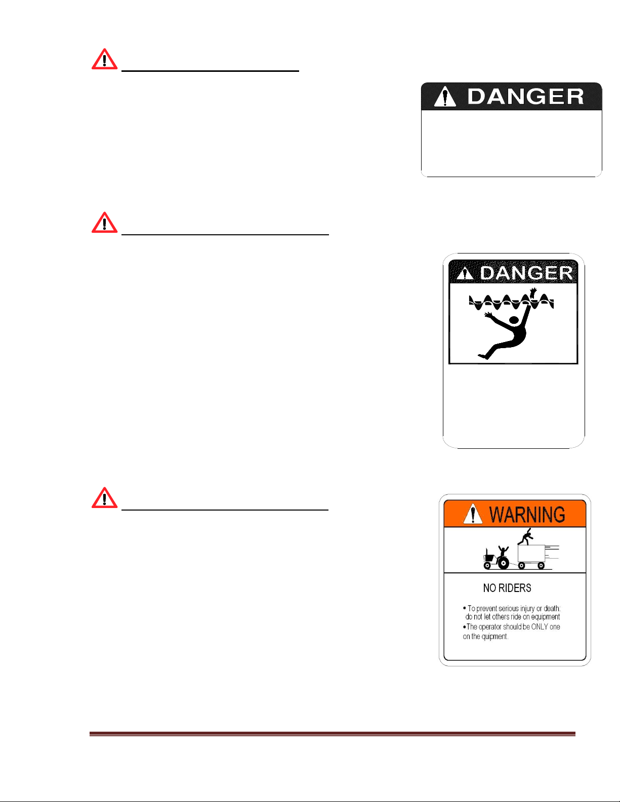
STAY CLEAR OF ROTATING DRIVELINES
Entanglement in rotating driveline can cause serious injury or
death.
Keep tractor master shield and driveline shields in place at all
times. Make sure rotating shields turn freely.
Wear close fitting clothing. Stop the engine and be sure PTO
driveline is stopped before making adjustments, connections, or
cleaning out PTO driven equipment.
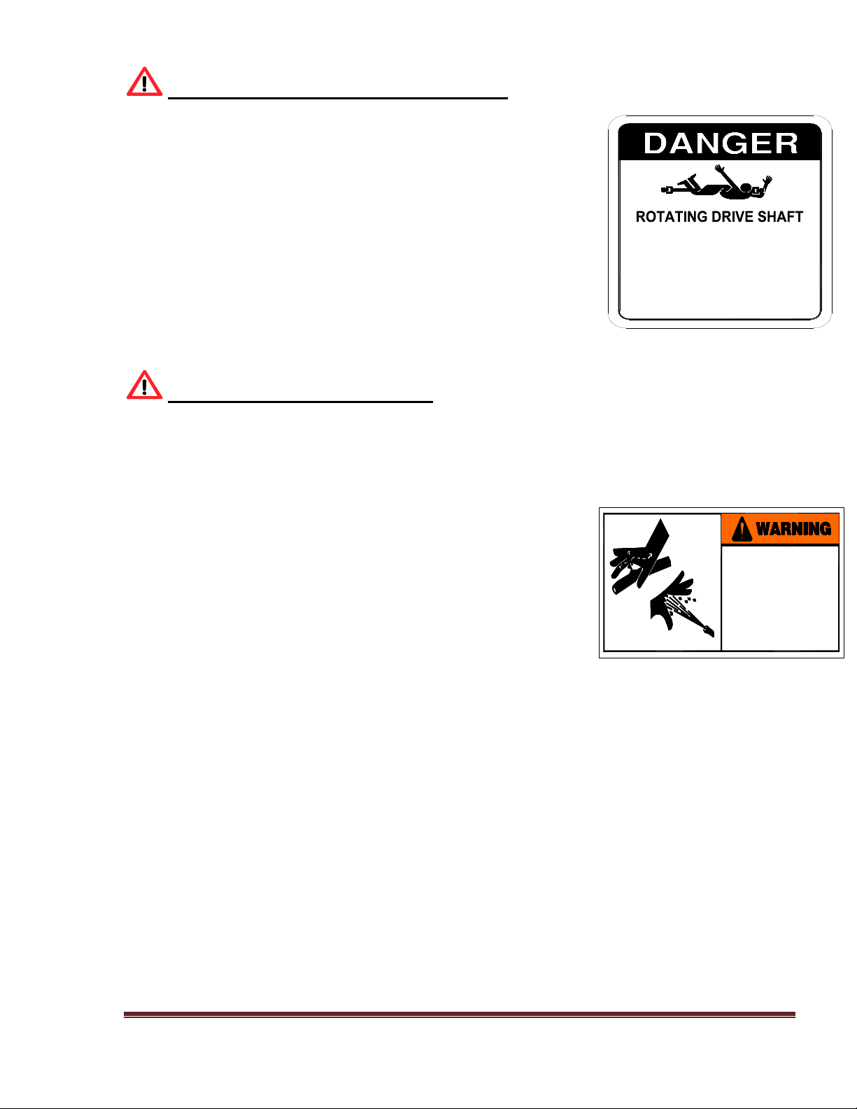
AVOID HIGH-PRESSURE FLUIDS
Escaping fluid under pressure can penetrate the skin causing serious
injury or death.
Avoid the hazard by relieving pressure before disconnecting hydraulic
or other lines. Tighten all connections before applying pressure.
Search for leaks with a piece of cardboard. Protect hands and
body from high pressure fluids.
If an accident occurs, see a doctor immediately. Any fluid injected
into the skin must be surgically removed within a few hours
or gangrene may result. Doctors unfamiliar with this type of injury
should reference a knowledgeable medical source.
SERVICE AND ADJUSTMENT
OF HYDRAULIC SYSTEM
SHOULD ONLY BE PERFORMED
BY QUALIFIED PERSONNEL.
IMPROPER ADJUSTMENT COULD
CAUSE SERIOUS INJURY,
DAMAGE TO SYSTEM,
AND VOID WARRANTY.
DO NOT WORK ON
WITHOUT DISCONNECTING
POWER SOURCE
KM 07

VI-MMXII Page 14
PREPARING TRACTOR FOR TRAILER MIXER
IMPORTANT: Drive components can be damaged from excessive speed. Do not operate tractor at
speeds in excess of recommended PT0 rpm.
This feed mixer may be equipped with either a 1000 RPM or a 540 RPM driveline.
Match tractor PTO with the feed mixer driveline.
IMPORTANT: To prevent driveline damage, adjust tractor drawbar to recommended setting.
Disengage power to tractor PTO before turning tractor.
Remove clevis if equipped. Turn offset drawbar down.
Adjust drawbar length.
ADJUST TRAILER HITCH CLEVIS
Mixer should be approximately level when attached to tractor.
SAFETY DECAL CARE
Keep safety decals and signs clean and legible at all times.
Replace safety decals and signs that are missing or have become illegible.
Replaced parts that displayed a safety sign should also display the current sign.
Safety decals or signs are available from your dealer or Kirby Manufacturing.
VI-MMXII Page 15
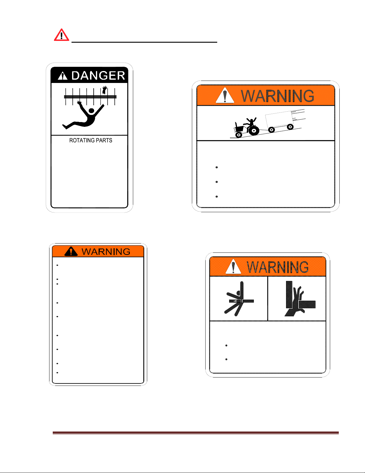
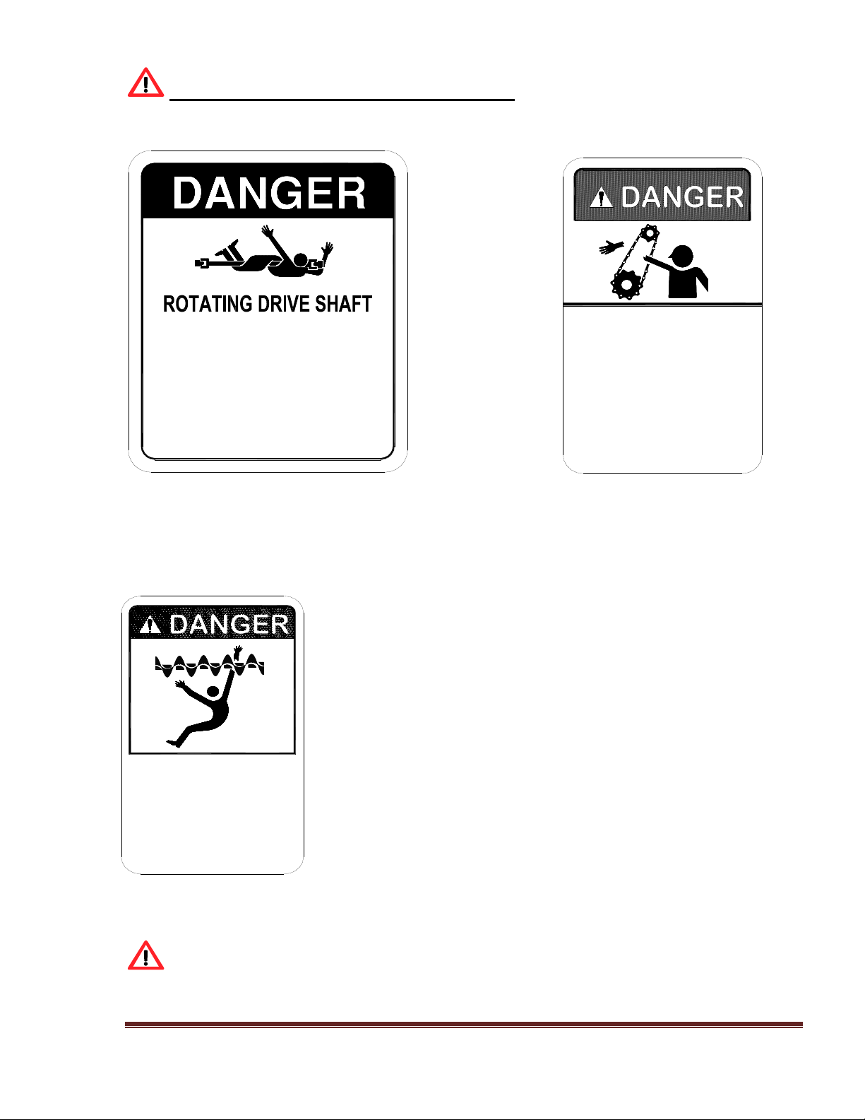
REPLACEMENT SAFETY DECALS
Immediately replace all and any worn or damaged Safety Decals. When ordering replacement
decals please provide the unit’s serial and model number.
Figure A Figure B
DANGER, Rotating Parts WARNING, Run-Away Hazard
Part No. KM-09 Part No. W-300
Figure C Figure D
WARNING To prevent Serious Injury WARNING, Crushing Hazard
Part No. W-100 Part No. W-200
Disengage PTO before
servicing, cleaning, or
clearing a clogged machine.
Stay off machine when it's
running.
Machine can be hazardous
in the hands of an
UNFAMILIAR, UNTRAINED, or
COMPLACENT operator.
Don't risk INJURY or DEATH.
KM 09
down steep grades.
RUN-AWAY HAZARD
To prevent serious injury or death:
Shift to lower gear before going
Keep towing vehicle in gear at
Never exceed a safe travel speed.
all times.
W-300
To prevent serious injury or death:
Read and understand owner's
manual before using. Review safety
precautions annually.
No riders allowed when transporting.
Securely attach to towing unit. Use
a high strength appropriately sized
hitch pin with a mechanical retainer
and attach safety chain.
Do not exceed 20 mph (33kph).
Slow down for corners and rough
terrain.
Do not drink and drive.
Before moving running gear, be sure
required lights and reflectors are
installed and working.
Before maintenance or repair, stop
vehicle, set parking brake, and
remove ignition key.
Place safety stands under frame and
chock wheels before working on
tires or running gear.
Maintain wheel bolts at torque as
recommend in the manual.
If equipped with brakes, maintain
proper adjustment.
W-100
CRUSHING HAZARD
To prevent serious injury or death:
Keep hands and body out of hitch
area when attaching towing vehicle.
Keep body clear of crush point
between towing vehicle and load.
W-200
VI-MMXII Page 16
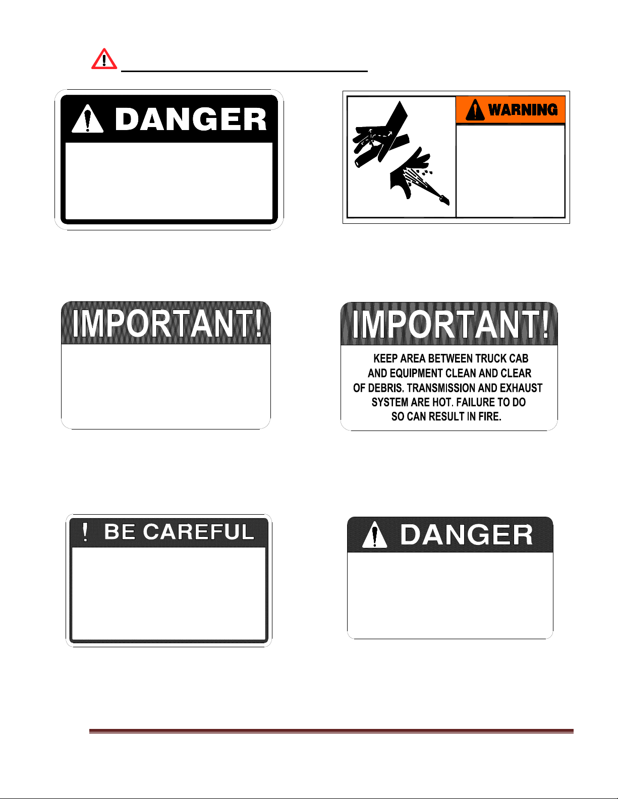
REPLACEMENT SAFETY DECALS; (cont.)
Figure E Figure F
DANGER; use only authorized WARNING; service and adjust
Part No. KM-02 Part No. W-100
Figure G Figure H
IMPORTANT; auger bolts must be kept IMPORTANT; keep area between
Part No. N/A Part No. N/A
Figure I Figure J
BE CAREFUL; keep all shield in place Danger; beware of moving parts
Part No. KM-10 Part No. KM-01
USE ONLY AUTHORIZED
KIRBY SHEAR PINS
KM-02
SERVICE AND ADJUSTMENT
OF HYDRAULIC SYSTEM
SHOULD ONLY BE PERFORMED
BY QUALIFIED PERSONNEL.
IMPROPER ADJUSTMENT COULD
CAUSE SERIOUS INJURY,
DAMAGE TO SYSTEM,
AND VOID WARRANTY.
OR MISSING BOLTS.
REPLACEMENT.
CHECK MONTHLY FOR LOOSE, DAMAGED
AUGER BOLTS MUST BE KEPT TIGHT!
USE ONLY KIRBY AUGER BOLTS FOR
8. MAKE CERTAIN EVERYONE IS CLEAR OF MACHINE BEFORE STARTING ENGINE
LUBRICATE, CLEAN OR UNCLOG MACHINES, UNLESS OTHERWISE SPECIFICALLY
7. USE FLASHING WARNING LIGHTS WHEN OPERATING ON HIGHWAYS EXCEPT
1. KEEP ALL SHIELDS IN PLACE.
WHEN PROHIBITED BY LAW.
OBSERVATION IS PROVIDED.
5. KEEP OFF EQUIPMENT UNLESS SEAT OR PLATFORM FOR OPERATION AND
4. KEEP HANDS, FEET AND CLOTHING AWAY FROM POWER DRIVEN PARTS.
3. WAIT FOR ALL MOVEMENT TO STOP BEFORE SERVICING THE MACHINE.
RECOMMENDED IN THE "OPERATORS MANUAL".
2. STOP ENGINE BEFORE LEAVING OPERATOR'S POSITION TO ADJUST,
6. KEEP ALL OTHERS OFF.
OR OPERATION.
KM 10
MOVING PARTS KEEP
ALL SHIELDS IN PLACE
BEWARE OF
KM 01
VI-MMXII Page 17
REPLACEMENT SAFETY DECALS; (cont.)
Figure K Figure L
DANGER; drive shaft DANGER; if you can read this
Part No. KM-07 Part No. KM-05
Figure K
DANGER; rotating auger
Part No. KM-03
Your best assurance against accidents is a careful and responsible operator. If there is
any portion of this manual or function you do not understand, contact your dealer or Kirby
Manufacturing.
DO NOT WORK ON
WITHOUT DISCONNECTING
POWER SOURCE
KM 07
IF YOU CAN READ
THIS, THE SHIELD
IS NOT IN PLACE
SHUT MACHINE OFF
REPLACE SHIELD
MOVING PARTS-
FAILURE TO HEED
CAN RESULT IN
DEATH
KM-05
ROTATING AUGER
HAVE SPOUT IN UP
POSITION WHEN MIXING
KEEP HANDS AWAY
FAILURE TO HEED
WILL RESUL IN
PERSONAL INJURY
OR DEATH
KM 03

VI-MMXII Page 18
BEFORE OPERATION
Carefully study and understand this manual. Note: it is the responsibility of the owner to train all
current, new and future operators of the equipment. If assistance is needed, please contact Kirby
Manufacturing.
Do not wear loose-fitting clothing which may catch in moving parts.
Always wear protective clothing and substantial shoes.
Keep wheel lug nuts or bolts tightened to specified torque.
Assure that agricultural implement tires are inflated to the proper pressure.
Prior to operating the equipment, give the equipment a visual inspection for any loose bolts, worn
parts or cracked welds, and make necessary repairs. Follow the maintenance safety instructions
included in this manual.
Be sure that there are no tools lying on or in the mixer/feeder.
Do not use the unit until you are sure that the area is clear, especially of children and animals.
Always check inside of mixer prior to starting it up.
Because it is possible that this mixer/feeder may be used in dry areas or the presence of combustibles,
special precautions should be taken to prevent fires and firefighting equipment should be readily
available.
Don’t hurry the learning process or take the unit for granted. Ease into it and become familiar with
your new mixer/feeder.
Practice operation of your mixer/feeder and its attachments. Completely familiarize yourself and
other operators with its operation before using.
Securely attach to towing unit. Use a high strength, appropriately sized hitch pin with a mechanical
retainer.
Do not allow anyone to stand between the tongue or hitch and the towing vehicle when backing up
to the mixer/feeder.

VI-MMXII Page 19
DURING OPERATION
Beware of bystanders, particularly children! Always look around to make sure that it is safe to
start the engine of the towing vehicle or move the unit. This is particularly important with higher
noise levels and quiet cabs, as you may not hear people shouting. NO PASSENGERS ALLOWED
- Do not carry passengers anywhere on, or in, the tractor or equipment, except as required for
operation.
Keep hands and clothing clear of moving parts. Do not clean, lubricate or adjust your mixer/feeder
while it is running.
Be especially observant of the operating area and terrain - watch for holes, rocks or other hidden
hazards. Always inspect the area prior to operation.
Do not operate on steep slopes as overturn may result. Operate up and down (not across)
intermediate slopes. Avoid sudden starts and stops. Pick the most level possible route when
transporting across fields. Avoid the edges of ditches or gullies and steep hillsides. Be extra careful
when working on inclines.
Periodically clear the equipment of hay, feed, twine or other materials to prevent buildup of dry
combustible materials.
Maneuver the tractor or towing vehicle at safe speeds. Avoid overhead wires or other obstacles.
Contact with overhead lines could cause serious injury or death. Allow for unit length when making
turns.
Do not walk or work under raised components or attachments unless securely positioned and
blocked.
Keep all bystanders, pets and livestock clear of the work area.
Operate the towing vehicle from the operator’s seat only. Never stand alongside of the unit with
engine running. Never attempt to start engine and/or operate machine while standing alongside of
unit.
Never leave a running mixer/feeder unattended.
As a precaution, always check the hardware on mixer/feeder prior to operating the equipment.
Correct all problems. Follow the maintenance safety procedures.
FOLLOWING OPERATION
Following operation, or when unhitching, stop the tractor or towing vehicle, set the brakes, disengage
the PTO and all power drives, shut off the engine and remove the ignition keys.
Store the unit in an area away from high traffic areas.

VI-MMXII Page 20
To prevent damage to the equipment and injury to livestock, do not park equipment where it will
be exposed to livestock for long periods of time.
Do not permit children to play on or around the stored unit.
Make sure parked machine is on a hard, level surface and engage all safety devices.
Wheel chocks should be used to prevent unit from rolling.
HIGHWAY AND TRANSPORT OPERATIONS
Keep the brake pedals latched together at all times. Never use independent braking with machine in
tow as loss of control and/or upset of unit can result.
Always drive at a safe speed relative to local conditions and ensure that your speed is low enough
for an emergency stop to be safe and secure. Keep speed to a minimum.
Reduce speed prior to turns to avoid the risk of overturning.
Avoid sudden uphill turns on steep slopes.
Always keep the tractor or towing vehicle in gear to provide engine braking when going downhill.
Do not coast.
Comply with state and local laws governing highway safety and movement of farm machinery on
public roads.
Use approved accessory lighting, flags and necessary warning devices to protect operators of other
vehicles on the highway during daylight and nighttime transport. The use of flashing amber lights is
acceptable in most localities. However, some localities prohibit their use. Local laws should be
checked for all highway lighting and marking requirements.
When driving the tractor and mixer/feeder on the road or highway under 20 MPH (40 KPH) at night
or during the day, use flashing amber warning lights and a slow-moving vehicle (SMV)
identification emblem.
Plan your route to avoid heavy traffic. Be a safe courteous driver. Always yield to oncoming traffic
in all situations, including narrow bridges, intersections, etc.
Be observant of bridge loading ratings. Do not cross bridges rated lower than the gross weight at
which you are operating. Watch for obstructions overhead and to the side while transporting.
Always operate mixer/feeder in a position to provide maximum visibility at all times.
Make allowances for increased length and weight of the mixer/feeder when making turns, stopping
the unit, etc.

VI-MMXII Page 21
PERFORMING MAINTENANCE
Good maintenance is your responsibility. Poor maintenance is an invitation to trouble.
Make sure there is plenty of ventilation. Never operate the engine of the towing vehicle in a closed
building. The exhaust fumes may cause asphyxiation.
Before working on the mixer/feeder, stop the towing vehicle, set the brakes, and disengage the PTO
and all power drives, shut off the engine and remove the ignition keys.
Be certain all moving parts on attachments have come to a complete stop before attempting to
perform maintenance.
Always use a safety support and block the wheels. Never use a jack to support the machine.
Always use the proper tools or equipment for the job at hand.
Use extreme caution when making adjustments.
Never use your hands to locate hydraulic leaks on attachments. Use a small piece of cardboard or
wood. Hydraulic fluid escaping under pressure can penetrate the skin.
When disconnecting hydraulic lines, shut off hydraulic supply and relieve all hydraulic pressure.
Openings in the skin and minor cuts are susceptible to infection from hydraulic fluid. If injured by
escaping hydraulic fluid, see a doctor at once. Gangrene can result. Without immediate treatment,
serious infection and reactions can occur.
Replace all shields and guards after servicing and before moving. After servicing, be sure all tools,
parts and service equipment are removed.
Do not allow grease or oil to build up on any step or platform.
Never replace hex bolts with less than grade five (5) bolts unless otherwise specified.
Where replacement parts are necessary for periodic maintenance and servicing, genuine factory
replacement parts must be used to restore your equipment to original specifications.
Kirby Manufacturing will not be responsible for damages caused using unapproved parts and/or
accessories. This will void your warranty.
If equipment has been altered in any way from original design, Kirby Manufacturing does not accept
any liability for injury or warranty.
A fire extinguisher and first aid kit should be kept readily accessible while performing maintenance
on this mixer/feeder.

VI-MMXII Page 22
2.0 MIXER STRUCTURE AND TRAILER
2.1 Observe for cracks in metal and welds in mixer chamber, trailer frame, and axle assembly and
around discharge door and chute. Re-weld as necessary.
2.2 Observe trailer hitch for
(I) Cracked welds. Re-weld as necessary.
(II) Bent or worn. Replace or repair as necessary.
2.3 Observe that all bolts are in place and that all sets crews are properly seated. Replace or
tighten as required.
2.4 Observe for hydraulic oil leaks. Repair any leaks.
2.5 Trailer mount only. Observe trailer tires:
(I) For cuts or punctures in tires.
(II) Check for proper inflation using pressure gauge.
(fill to the maximum pressure rating shown on side of tire)
2.6 Observe wheel hubs and bearings.
(I) Check for oil seal leaks. Replace if seal leaks.
(II) Check wheel hubs for proper bearing tightness. Tighten as required.
(III) Observe oil level in cap, oil must be level with bottom of filler hole. Fill with proper
lubricant to over flow.
3.0 MAIN AUGERS, SHAFTS, AND BEARINGS
CAUTION! THE MIXER SHALL NOT BE IN OPERATION FOR THE FOLLOWING:
3.1 Observe auger flighting, in mixing chamber
(I) Bent, deformed, or worn to less than 25% of new thickness.
(II) Replace flighting as necessary.
(III) Check blades on mixer replace when worn
3.1 Observe mixing chamber, sides and ends.
(I) Walls and ends should be straight, not bulging in appearance. This condition can result
from over loading or foreign objects present in ration.
(II) Look for signs of excessive wear
3.2 Observe tractor drive line and mixer drive line for bent shafts.
(I) Ensure all shields are in place and operational (sliding without restrictions)

VI-MMXII Page 23
4.0 SPROCKET AND CHAINS, (CROSSFEED)
4.1 Observe chain for properly seating on sprocket. Use caution while observing mixer while in
operation. Look for chain jerking motion, when chain wraps around sprocket. Jerking motion
may indicate:
(I) Misalignment of chain and sprocket. Realign
(II) Worn or loose chain. Replace worn chain.
(III) Loose chain idlers. Reposition and tighten idler.
(IV) Bent shafts. Replace with new shafts.
4.2 Observe sprocket tooth wear pattern.
(I) Tooth worn on sides indicates misalignment. Realign sprocket.
(II) Tooth worn to a sharp point indicates loose or worn chain. Adjust sprockets
(III) Tooth worn to cup at base indicates excessive load on chain. Adjust sprockets
4.3 Observe sprockets for the following.
(I) Main key sheared or shearing. Replace key.
(II) Main set screws loose or missing. Tighten or replace.
(III) Movement or signs of movement of sprockets on shaft. Tighten or replace.
(IV) Alignment - Using a straight bar, insure that both sprocket faces are in full contact with
the edge of the bar.
5.0 GEAR BOXES
5.1 Main planetary drive.
(I) Observe oil level of gearbox reservoirs, use clear view tube on oil reservoir.
(II) Observe for any over-fill oil coming out of the gearbox oil reservoir tank.
5.2 Two speed gearboxes
(I) Observe shaft seals for leaks. Replace seals.
(II) Check for loose bolts that secure gearbox to mounting bracket.
(III) Check for misalignment to other components: U-joints. Shear hub
(IV) Check input shaft, movement indicates worn bearings. Replace.
(V) Check out put shaft for movement, realign and tighten set screws.
(VI) Check to see that the oil is level with the filler plug located on the side of this gearbox.
Fill to overflow.
(VII) Check tightness of gearbox mounting bolts.
Check shifting lever and cables. Adjust cable for optimum engagement in both high and low speed
selections on gearbox.
5.3 For regular service, refer to the “Preventive Maintenance and Lubrication Schedule” located
in Section 8 of the manual.

VI-MMXII Page 24
6.0 DRIVELINES AND POWER TAKEOFFS
6.1 Tractor PTO driveline
(I) Shields must be secured by locking devices
(II) Shields must slide freely.
(III) Observe shields for damage.
(IV) Driveline shafts must slide freely, binding may cause false readings on the scale
system. Lubricate all shaft splines.
(V) U-joints cross & yoke must fit tight in the bearing cups and have zerk fittings for
lubrication.
6.2 Truck mounted mixer PTO’s
(I) Observe for oil leaking around PTO shaft seal. Replace seal.
(II) Check PTO for loose bolts holding PTO to transmission or engine crank shaft. Tighten
bolts.
(III) Check U-joints, bearings, yokes, and set bolts. Replace worn parts and tighten all
bolts.
(IV) Lubricate driveline “U” joints as per the “Preventive Maintenance and Lubrication
Schedule”
6.3 Mixer drive line.
(I) Check for loose or missing set screws or lock collars in pillow block bearings and
driveline yokes. Tighten or replace lock collars set screws.
(II) Check for loose or missing bolts in pillow block bearings. Tighten or replace.
(III) Observe driveline under operation. CAUTION STAY CLEAR OF ALL MOVING
PARTS, DO NOT WEAR LOOSE CLOTHING!!
(IV) Check for vibration, worn bearings, bad U-joint bearings, or bent shaft. Replace worn
or damaged parts.
(V) Observe for linear movement through bearings, this is indicated by unpainted surface of
shaft exposed on each side of bearing locking collar. Realign and tighten loose locking
bolts.
(VI) Observe for loose set screws or PTO shaft not slipping in sleeve, causing end thrust load
on the bearings.
(VII) Check for bent shaft. Replace and grease as per lubrication schedule.

VI-MMXII Page 25
7.0 MAIN HYDRAULIC SYSTEM
STATIONARY AND TRUCK MOUNTED VERTICAL MIXERS
QUICK REFERENCE INFORMATION
Thank you for your investment in a Kirby hydraulic driven mixer. With proper care and service you
can extend the life of the hydraulic system.
Your system is equipped with two (2) Sauer-Sundstrand Series 90 axial piston pumps, two (2)
Parker/VOAC variable displacement hydraulic motors Series V14 and two (2) Fairfield planetary
gearboxes.
In order to ensure hydraulic system efficiency only fresh, clean oil should be added to the hydraulic
tank. ALL hydraulic oil that is added to the system must be filtered through a 10-micron filter to
ensure oil cleanliness. If any lines are damaged, unfastened or replaced, extreme care must be
taken to prevent dirt from entering the hydraulic system. All open lines should be capped. Filter
indicator should be checked regularly and the filters should be replaced if indicated, or as hours of
use require. When replacing the filters always replace O-ring on canister.
Kirby Manufacturing recommends that only authorized Kirby filters be used for replacement. The
filters used must be at least a 10-micron filter. Oil specifications are Pennzoil AW68.
It is critical that proper maintenance and filter changes be made on a regular basis. Warranty is based
on the regular maintenance of your system. Not changing your oil and filters properly and within the
time frame given WILL VOID YOUR WARRANTY. All filters should be kept clean and free of
foreign contaminants when replacing to avoid oil contamination.
All hydraulic filters and all planetary gearbox oil should be changed after the first initial 50 hours
of use. Thereafter, all hydraulic filters should be changed every 500 hours. Use the reservoir filter
gauges, located on the top of the hydraulic fluid reservoir, to help determine when the next filter
change is necessary.
The first oil change on the planetary gearboxes should occur after 50 hours of use. Thereafter, oil
changes should occur every 1,000 hours.

VI-MMXII Page 26
Procedure for changing the oil in the planetary gearbox:
1. First, run unit to warm oil in gear boxes
2. To drain the planetary gearbox oil, place a bucket under the planetary gearbox to catch the
used oil, detach the bottom hose (the other end of this hose goes to the bottom of gear oil
supply reservoir) from the bottom of the gearbox. Let the oil from the gearbox and the bottom
hose drain into the bucket.
3. Take the plug out of the end of the gearbox’s top hose. This is the other hose that hangs down
from the side of the planetary gearbox. Place an air hose to the end of the top hose. Using
compressed air (no more than 20 psi.) gently force the oil out the bottom of the gearbox.
Note: Excessive air pressure could damage the top output seal of the gearbox.
4. To fill the gearbox, re-attach the bottom hose to the bottom of the gearbox.
5. Add (warm) oil through the reservoir fill cap, located on the reservoir, until oil comes out of
the end of the top hose.
6. Re-place plug in top hose and (if needed) add oil until oil reaches fill line on sight glass and
check periodically to ensure that the level is correct.
Recommended oil for this gearbox is PENNZOIL MULTI-PURPOSE GEARLUBE 4140,
GRADE SAE-85W-140 with “EP” (Extreme Pressure) additive (for other oil choices see the
additional specification listed below)
If you have opted for the “Extended Warranty”, you will be provided with oil sampling kits. You
should use these kits when pulling oil samples on your equipment. It is crucial that oil samples be
pulled in accordance to the provided schedule. YOUR WARRANTY WILL BE VOID IF ONE
OIL SAMPLING TEST IS MISSED.
Once your oil sample is sent in and analyzed, the information will then be sent back to you. This
information will provide you with valuable information on the condition and maintenance of your
hydraulic system. It is your (the customer’s) responsibility to maintain the oil cleanliness to the
specifications provided. OIL SAMPLING SHOULD BE DONE WITH EVERY OIL FILTER
CHANGE, INCLUDING THE FIRST 50 HOURS.
After you receive your fluid analysis report, you should check it to ensure that it meets or exceeds
the specifications stated. For hydraulic oil the “cleanliness code” specifications are as follow: Your
hydraulic oil should be in the 18/16/13 range. Any sampling that is lower than this is good; any
sampling that is higher is an indication that your oil is not clean and thus will reduce the life
expectancy of your system. You must immediately change your hydraulic filters and oil. Then run
the unit for 50 hours and take another sample.
ISO CODE MEANING
18/16/13 = # of particles
Particles > 2 microns Particles > 15microns
Particles > 5 microns

VI-MMXII Page 27
If you have opted for the “Extended Warranty”, you will receive all the necessary oil sampling
kits when you receive your equipment. It is the customer’s responsibility to pull the oil samples
and send them in for analysis. All mail charges will be paid by the customer.
At this time, we suggest you buy your next set of change of filters. It will require two (2) intank element part # 7954, two (2) charge pump filters # 7956, and two (2) small breather filters
part # 7953 B (located on the side of the filler cap near the top of the hydraulic oil reservoir).
We recommend that you NEVER use paper element filters. Kirby offers a high efficiency, and
high capacity Microglass III type.
Oil temperature, cooling system and low fluid volume shut-down
Your unit is equipped with a hydraulic oil temperature readout (optional read-out) and hydraulic oil
cooling system.
Normal operating temperature range of your system depends on ambient temperature and duty cycle.
The range should vary between 150 and 180 degrees Fahrenheit.
An automatic hydraulic shut-off for the system is set at 190 degrees Fahrenheit. If the hydraulic oil
reaches the 190-degrees mark, the hydraulic system will automatically shut down.
You will still be able to drive your truck (truck mounted models), but the system will not come back
on until the oil cools down. If this failure occurs and you are unable to find the cause, call Kirby
Mfg. Inc 209-723-0778 for further assistance.
Your system has a hydraulic oil cooling system equipped with fan(s), which automatically will turn
on when the oil temperature reaches 120 degrees. The radiator for this system should be cleaned on
a daily basis. NOTE: be careful not to damage cooling fins on radiator when using compressed air
to blow out radiator. You should periodically physically check the fans to ensure they are working
when the hydraulic fluid temperature is above 120 degrees. DO NOT use water for cleaning the
hydraulic cooler.
Your unit is also equipped with a low volume hydraulic sensor in the hydraulic fluid reservoir. If for
any reason there is a loss of hydraulic fluid in the system the unit will automatically shut down. For
truck mounted units with front mounted pumps, the truck engine must not be started. SEVERE
DAMAGE will occur to the hydraulic system if you run the truck engine after the hydraulic
system has automatically shut down.
A check of the system should be made to determine the cause of the low volume shut-down. If for
whatever reason, your unit is not equipped with the “automatic shut-down” feature and you have a
major loss of hydraulic fluid in the system, you must shut down the truck engine immediately or
the hydraulic system will be severely damaged.

VI-MMXII Page 28
GENERAL CHECK LIST
7.1 Observe all fittings, pipes, tubes, and hoses for leakage. Tighten as needed.
7.2 Observe oil level in main tank. On truck mount or stationary units the dipstick capacity allowed
is 95 liters. (25 gallons)
7.3 On tractors, the maximum pump capacity required to operate the mixer is 53 liters per minute
(14 gpm) @ 2200 P.S.I.. The minimum pump capacity required to operate the mixer is 46 liters
per minute (12 gpm) @ 2200 P.S.I..
7.4 Manifold block specification is 53 liters per minute (14 gpm) @ 3000 P.S.I. Caution: do not
exceed these limits.
7.5 Manifold relief valve is factory set @ 2200 P.S.I. for maximum safety to the system.
7.6 Manifold needle valve controls the speed at which the door opens. It may be adjusted as needed.
7.7 Discharge conveyor motor specification, maximum 57 liters per minute (15 gpm) @ 1700 P.S.I.
7.8 Discharge conveyor motor under normal operation requires a minimum of 46 liters per minute
(12 gpm) to a maximum of 53 liters per minute (14 gpm) to provide adequate unload speed. The
speed is controlled through the crossfeed flow control valve located on the mixer.
7.9 Stalling of the discharge conveyor motor may be caused by the loss of oil pressure (P.S.I.) to the
motor, due to incorrect adjustment of relief valve, or worn pump/ motor.
7.10 Slow speed of discharge conveyor motor may be caused by the loss of oil flow from the pump
source to the motor, due to worn pump or restricted flow in the tractor hydraulic system/hydraulic
hoses.
7.11 Truck mount and Stationary mixers have 12-volt solenoid valves to operate conveyor motor and
hydraulic door. Solenoids may be shifted manually by inserting 1/8” shaft into the hole at each
end of solenoid. This method will determine if the 12-volt power supply or the switches are
defective. This method can also be used to determine if the solenoid is struck or otherwise
defective resulting in a problem with the operation of the discharge.
7.12 For service see preventive maintenance and lubrication schedule in Section 8.
 Loading...