

Page 1
WARNING
Kirby Morgan® Models 18 & 28 Band Masks
Operations and Maintenance Manual
KMDSI Part # 100-002
™
Kirby Morgan Dive Systems, Inc.
1430 Jason Way
Santa Maria, CA 93455, USA
Telephone (805) 928-7772, FAX (805) 928-0342
E-Mail: KMDSI@KirbyMorgan.com, Web Site: www.KirbyMorgan.com
Manual prepared by KMDSI, Marine Marketing and Consulting, and Dive Lab, Inc.
®
NOTE: This manual is the most current for the Kirby Morgan 18 & 28 BandMasks®. It is page dated August 2010.
Future changes will be shown on page III and the changed pages will carry the date of change. Previous manuals may
not reflect these updates.
Diving with compressed breathing gas is a hazardous activity. Even if you do everything
right there is always the danger that you may be killed or injured. No piece of diving
equipment can prevent the possibility that you may be killed or injured any time you
enter the water.
The Kirby Morgan 18 & 28 BandMasks® meet or exceed all performance and testing requirements of all
government and non-government testing agencies throughout the world. They are CE approved. They
are approved for use on all commercial and military work underwater. Only Kirby Morgan masks and
helmets have achieved the CR (Commercial Rated) mark, the highest United States of America rating.
Kirby Morgan, SuperLite®, BandMask®, BandMask®, KMB, KMB-BandMask®, DSI, Diving Systems International, EXO, REX®,
SuperFlow and DECA are all registered trademarks of Kirby Morgan Dive Systems, Inc. Use of these terms to describe products
that are not manufactured by KMDSI is illegal.
The two dimensional images (such as photographs and illustrations) of our products are © copyrighted and trademarks of Kirby
Morgan Dive Systems, Inc. The three dimensional forms of our products are trademark/trade dress protected.
© Copyright 1970-2010 Kirby Morgan Dive Systems, Inc. All rights reserved. This manual is made available for the express use
of owner of this Kirby Morgan product. No part of this manual may be reproduced, stored in any retrieval system, or transmitted,
or used in any form or by any means, whether graphic, electronic, mechanical, photocopy, or otherwise by technology known or
unknown, without the prior written permission of Kirby Morgan Dive Systems, Inc.
Document Number 100720002, August 2010
Page 2

Kirby Morgan® BandMasks® 18 & 28
Warranty Information
Kirby Morgan Dive Systems, Inc. warrants every new mask, helmet, or KMAC Air Control System
to be free from defects in workmanship for a period of three hundred sixty five (365) days from date
of purchase. This warranty covers all metal, fiberglass, and plastic parts. This warranty does NOT
cover rubber parts, communications components, or headliners. In addition, due to the electrolytic
nature of underwater cutting and welding, chrome plating cannot be warranted when the diver engages in these activities.
Should any part become defective, contact the nearest authorized KMDSI dealer. If there is no
dealer in your area, contact KMDSI directly at (805) 928-7772. You must have a return authorization from KMDSI prior to the return of any item, Upon approval from KMDSI, return the defective part, freight prepaid, to the KMDSI plant. The part will be repaired or replaced at no charge as
deemed necessary by KMDSI.
This warranty becomes null and void if:
1) The product is not registered with KMDSI within ten (10) days of purchase.
2) The product has not been properly serviced and/or maintained according to the appropriate KMDSI manual. In addition, the user is responsible to ensure that all product updates
as recommended by KMDSI have been performed.
3) Unauthorized modifications have been made to the product.
4) The product has been abused or subjected to conditions which are unusual or exceed the
product’s intended service.
NOTE: Be sure to complete the enclosed warranty card and return it to KMDSI immediately. No
warranty claims will be honored without a satisfactorily completed warranty card on file at KMDSI.
II © Copyright 1970-2010 Kirby Morgan Dive Systems, Inc. All rights reserved. Document #100720002
Page 3
®®
Location
Number Order No. Description
1 510-509 Head Harness (Spider)
2 525-740 KMB Hood Assembly
3 545-015 Nose Block Device
510-575 Nose Block Pad
4 520-020 Valve Body
5 510-550 Valve, Oral Nasal
6 530-060 Screw ( 18 only)
7* 510-490 O-Ring (18 only)
510-211 O-Ring (28 & pre '99 18)
8* 550-081 Regulator Mount Nut (18 only)
550-038 Regulator Mount Nut
(28 & pre '99 18)
9 510-747 Oral Nasal Mask
10 515-0 05 Earphone, Right
11 515-006 Earphone, Left
510-542 Earphone Cover set
515-008 Speaker
520-0 15 Speaker Protector
12 515-009 Microphone
13 515-030 Communications Set
14 520 -051 Comfort Insert (18 only)
15 530-095 Screw
16 545-007 Top Band
17* 520 -056 Mask, Fiberglass (18 only)
520 -055 Mask, Fiberglass (18 only, pre '99)
520-125 Mask,Frame (
28, 1"
)
520-096 Mask,Frame (⅞")
18 530-535 Washer
19 530 -415 Washer
20 530-317 Nut
21 545-016 Air Train
21a 510-762 Air Train Gasket KMB 18 ONLY
22 530-317 Nut
23 530-535 Washer
24 545-065 Standoff (28 only)
25 530-050 Screw
26 510-260 O-Ring
27 520 -004 Face Port (18 only)
520-128 Face Port (28 & pre 1979 18's only)
28 560 -070 Port Retainer
28n 550-116 Nose Block Guide
29 530-052 Screw, Port Plug
30 530-035 Screw
31 510-010 O-Ring
32 510-008 O-Ring
33 555-180 Packing Nut
34 550-062 Knob, Nose Block
35 525-752 Tri-Valve™ Exhaust (35a-35i)
35a 510-786 Starboard Whisker™
35b 510-787 Port Whisker™
35c 510-761 Tri-Valve Exhaust Main Body
35d 520-200 Whisker™ Exhaust Valve Insert
35e 510-776 Exhaust Valve
35f 520-042 Tie Wrap
35g 520-118 Tri/Quad Valve Whisker Clamp
35h 530-008 Brass Screw
35i 530-009 Brass Nut
36 550-061 Spacer
37 540 -015 Plate
38 530-045 Screw
39* 545-080 Reg. Body, SuperFlow 350 (18 only)
545-022 Regulator Body
(28 pre 2004& pre '99 18 only)
40 550-060 Piston
41 535-807 Spring Set
42 550-059 Spacer
43 550-057 Shaft
Location
Number Order No. Description
44 520 -032 Washer
45 510-011 O-Ring
46 550-055 Packing Nut
47 550-053 Knob, Adjustment
48 530-601 Retaining Pin
49 530-030 Screw
50 545-020 Clamp
51 545-018 Cover Assembly
51a 535-905 Retaining Clip
51b 540-055 Cover
51c 535-810 Spring, Purge Button
51d 520-017 Purge Button
51e* 520-078 Purge Button Sticker (18 only)
520-077 Purge Button Sticker
(28 & pre '99 18)
52 510-553 Diaphragm
53 530-303 Nut
54 550-052 Spacer
55 545-038 Roller Lever
56 530-506 Washer
57* 530-505 Washer
58* 535-804 Spring
(pre '04 28 & pre '99 18)
(pre '04 28 & pre '99 18)
59 545-026 Inlet Valve
60 510-014 O-Ring
61a 550-046 Inlet Nipple, "A"
61b 550-048 Inlet Nipple, "B"
61c 550-050 Jam Nut, "B"
62 510-552 Exhaust Valve
62a 540-122 Exaust Flange, Chrome
62b 510-401 Gasket
62c 530-020 Screw
63a 505-026 Demand Regulator Assem. 18 "A" (⅞")
63b* 505-027 Demand Reg Assem."B"
(28 pre '05 & pre '99 18)
(⅞")
505-069 Demand Reg Assem. 350 18 "B",28 (1")
63c 505-028 Reg Adjustment Assem.
64 530-021 Screw
65 545-024 Exhaust Cover (18)
545-041 Exhaust Cover (28)
66 510-561 Main Exhaust Valve
67 550-063 Exhaust Body (18 only)
68 545-009 Bottom Band
69 530-035 Screw (18 only)
70 550-040 Nut
71 530-308 Hex Nut
72 530-525 Washer
73 515 -035 Communications Post
74 510 -481 O-Ring
75 550-043 Plug
76 555-175 Packing Gland
77 520-113 Ferrule Set
78 555-178 Packing Nut
79 515-045 W.P. Connector, Male (4 pin)
79a 505-047 W.P Connector Assem. complt.
80 515-049 Terminal
81 515-061 Terminal Block
82 550-019 Locknut
83 535-802 Spring
84 520-524 Knob, control
85 520 -030 Washer
86 550-020 Bonnet
87 510-015 O-Ring
88 520 -031 Washer
89 510-010 O-Ring
90 550-022 Valve Stem
91 550-023 Seat Assem.
© Copyright 2010 Kirby Morgan Dive Systems, Inc. All rights reserved. Document #100428001
Kirby Morgan 18 A/B & 28 Band Mask
Location
Number Order No. Description
92 550-024 Stud - Side Block
93a 550-026 Side Block - "A" N/A
93b 550-029 Side Block - "B"
94 550-140 Emergency Valve Body
95 550-138 Stem
96 540-095 Washer
97 520 -024 Packing
98 550-091 Packing Nut
99 520-525 Knob, Control
100 535-802 Spring
101 550-019 Locknut
102 505-070 Emergency Valve Assembly
103 555-195 One-Way Valve
104 555-117 Adapter, Brass, 1/4" NPT/0
105 Seat
106 Wiper
107 O-Ring
108 O-Ring
109 Poppet
110 Spring
Order
Complete
see
Loc. # 103
111 Body
112 510-483 O-Ring
113 505-060 One-Way Valve Assembly
114 550-095 L.P. Plug, w/O-ring
114b 310-003 O-Ring
115a 510-011 O-Ring
115b 520-033 O-Ring, Teflon
116 555-154 Bent tube Assembly
117a 510-010 O-Ring
117b 510-012 O-Ring
118a 555-152 Regulator Hose w/O-Rings
118b 555-155 Bent Tube Assem. w/O-Rings
119a 505-022 "A" Side Block Assem. Complt.-N/A
119b 505-024 "B" Side Block Assem. Complt.
120 540-175 Bottom BandKeeper® Attachment Plate
120a 540-182 Bottom BandKeeper® Mount
121 530-073 Screw
122a 540- 171 Top BandKeeper® Mount
122b 540-179 Top BandKeeper® Attachment Plate
122c 530-073 Screw
123 530-040 Screw
124 530-062 Screw
525-620 Tool Kit (not shown)
2
For
Replacement
Parts
Order
Kit
#525-330
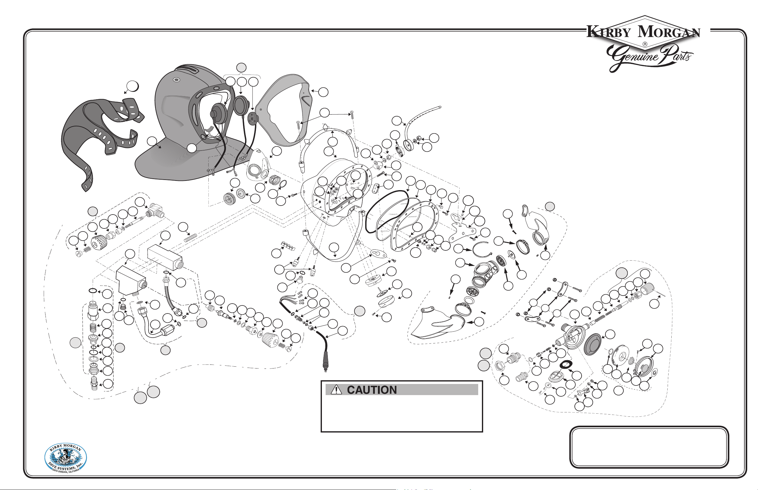
Use only Kirby Morgan original replacement parts. The use
of other manufacturer's parts will interfere with the performance
characteristics of your life support equipment and may jeopardize your
safety. Additionally, any substitutions will void any warranties offered
by KMDSI. When ordering spares, always insist on Kirby Morgan
original parts.
Following publication of this booklet, certain changes in standard equipment, options, prices and the like may
have occurred which would not be included in these pages. Your Authorized KMDSI dealer is your best source
for up-to-date information on any of these products. © Kirby Morgan Dive Systems, Inc. reserves the
right to change product specifications at any time without incurring obligations.
Kirby Morgan Dive Systems, Inc.® 1430 Jason Way, Santa Maria, CA 93455
Phone: 805/928-7772 Fax: 805/928-0342
www.KirbyMorgan.com e-mail: kmdsi@KirbyMorgan.com
Product Changes
Page 4
®
68
Kirby Morgan
1
2
3
4
5
6
7
8
9
10
11
12
13
14
15
16
17
73
74
75
71
72
18
24
25
26
27
28
29
30
31
28n
32
33
34
64
65
66
67
69
70
82
83
84
85
86
87
88
89
90
91
92
93a
94
95
96
97
98
93b
100
101
102
99
103
113
114b
114
112
111
110
109
104
105
108
106
107
115b
116
117b
115a
117a
118b
118a
119a
119b
81
77
78
80
79
79a
76
74
120
121
123
122c
122b
122a
124
21
22
23
20
21a
120a
19
Note: “21a” not needed for the KMB 28
36
37
38
39
40
41
42
43
44
45
46
47
48
63c
59
58
57
61a
60
52
61c
61b
63a
63b
50
49
51
51a
51b
51c
51e
51d
62
56
55
54
53
62a
62b
62c
35f
35b
35d
35e
35g
35h
35i
35c
35a
35
Kirby Morgan 18 A/B & 28 Band Mask
Kirby Morgan Dive Systems, Inc.® 1430 Jason Way, Santa Maria, CA 93455
www.KirbyMorgan.com e-mail: kmdsi@KirbyMorgan.com
Phone: 805/928-7772 Fax: 805/928-0342
Use only Kirby Morgan original replacement parts. The use
of other manufacturer's parts will interfere with the performance
characteristics of your life support equipment and may jeopardize your
safety. Additionally, any substitutions will void any warranties offered
by KMDSI. When ordering spares, always insist on Kirby Morgan
original parts.
© Copyright 2010 Kirby Morgan Dive Systems, Inc. All rights reserved. Document #100428001
As of January 1, 1999, all KMB 18B's are manufactured with
*
the large tube SuperFlow 350 Regulators, part number 505-069,
and a new frame part number 520-056. The large tube regulator
cannot be retrofitted into pre '99 KMB 18B's without the purchase
of a new frame. Small tube fiberglass frames, Part number 520-055,
are available as replacement parts (see 17)
Page 5

Kirby Morgan® BandMasks® 18 & 28
Record Of Changes
It is the responsibility of the owner of this product to register their ownership with Kirby Morgan Dive
Systems, Inc., by sending the warranty card provided. This card is to establish registration for any necessary
warranty work and as a means of communication that allows KMDSI to contact the user regarding this product.
The user must notify KMDSI of any change of address by the user or sale of the product.
All changes or revisions to this manual must be recorded in this document to ensure that the manual
is up to date.
Change Number Date Description of Change
1 05/21/2008 Reworded: Section 2.1 Product Specifications, 2.2.1 SuperFlow
350 Demand Regulators, 2.2.2 SuperFlow® 450 Performance, 2.7 Operational
Specifications & Limitations, Page 25 changed email address, Two warnings at
the bottom of page 26, Page 27 changed email address and Page 41 changed size
of text box to accommodate missing part number
Added: Appendix 3 and 4
®
and SuperFlow®
Removed: Tables 1 and 2 from chapter 2
2 08/20/2008 Page III Removed page number column.
Added: Last paragraph to chapter 5 on page 65. Heading changed.
Moved: Chapter 5 into two columns.
Changed: Section 7.8.8 Reassembly of the SuperFlow 350 Demand Regulator
to eliminate washer and spring text. Section 7.10.2.2 Regulator Exhaust Valve
Replacement, step 2 switching tie wraps for whisker clamps.
Page 65 Various text changes
Page 66 Added Whisker Clamp Replacement Kit: Part # 525-032 to second column.
3 11/05/2008 Table of contents redesign
Page 148 Various torque specification updates
4 03/23/2009 Page 40 Section 3.6.1 Step 8: Changed 13 kg cm to 1.3 Newton Meters.
Page 71 Section 6.4.5 2nd Paragraph: Changed 28 kg cm to 2.94 Newton Meters.
Page 75 Section 7.3.2: Changed 270 kg cm to 17 Newton Meters.
Page 76 Section 7.3.2 Step 7: Changed 270 kg cm to 17 Newton Meters.
Page 80 Section 7.4.4 Step 7: Changed 40 Inch Pounds to 15 Inch Pounds.
Page 88 Section 7.7.4 Step 8: Changed 150 Inch Pounds to 75 Inch Pounds.
Page 122 Section 8.4.3 Step 6: Changed 14 Inch Pounds to 12 Inch Pounds.
Page 138 Section 9.2.1 Step 10: Changed 112 kg cm to 11.3 and 4.5 Newton
Meters.
Page 145 Added 122c to Torque Specs
5 11/18/2009 Chapter 2: addition of CE conforming criteria
6 03/30/2010 Updated images of whisker wings
7 07/20/2010 Added wiring diagram to chapter 8.
© Copyright 1970-2010 Kirby Morgan Dive Systems, Inc. All rights reserved. Document #100720002 III
Page 6

Kirby Morgan® BandMasks® 18 & 28
WARNING
Diving with compressed breathing gas is a hazardous activity. Even if you do everything
right there is always the potential for serious injury or death. No one piece of diving
equipment can prevent the possibility that you may be injured or killed any time you
enter the water. We do not herein make any effort to teach the principles of diving. The
information in this manual is intended for users of Kirby Morgan masks and persons
that maintain or service Kirby Morgan masks.
IV © Copyright 1970-2010 Kirby Morgan Dive Systems, Inc. All rights reserved. Document #100720002
Page 7

Kirby Morgan® BandMasks® 18 & 28
Table Of Contents
Warranty Information . . . . . . . . . . . . . . . . . . . . . . . . . . . . . . . . . . . . . . . . . . . . . . . . . . . . . . . . . . . . . . . . . . . . . . . . . . . . . . . . II
Record Of Changes
Denition of Signal Words Used in this Manual
Chapter 1 General Information KMDSI Products . . . . . . . . . . . . . . . . . . . . . . . . . . . . . . . . . . . 1
1.1 Introduction
1.2 Full-Face Masks and Manifolds
1.3 Kirby Morgan Diving Helmets
Chapter 2 Description & Operational Specications
Kirby Morgan 18 & 28 . . . . . . . . . . . . . . . . . . . . . . . . . . . . . . . . . . . . . . . . . . . . . . . . . . . . . . . . . . . . . . . . . . . . . . . . . . 9
2.1 Product Specications
2.2 Regulator Performance
2.2.1 SuperFlow® and SuperFlow® 350 Demand Regulators . . . . . . . . . . . . . . . . . . . . . . . . . . . . . . . . . . . . . . . 9
2.2.2 SuperFlow® 450 Performance . . . . . . . . . . . . . . . . . . . . . . . . . . . . . . . . . . . . . . . . . . . . . . . . . . . . . . . . . . . . . . . 9
2.3 Cage Code
2.4 CR Standards
2.5 CE Certication
2.5.1 CE Marking . . . . . . . . . . . . . . . . . . . . . . . . . . . . . . . . . . . . . . . . . . . . . . . . . . . . . . . . . . . . . . . . . . . . . . . . . . . . . . . . . 10
2.5.2 Notifying Body . . . . . . . . . . . . . . . . . . . . . . . . . . . . . . . . . . . . . . . . . . . . . . . . . . . . . . . . . . . . . . . . . . . . . . . . . . . . . . 10
2.6 Risks in Decompression Diving . . . . . . . . . . . . . . . . . . . . . . . . . . . . . . . . . . . . . . . . . . . . . . . . . . . . . . . . . . . . . . . 10
2.7 Operational Specications & Limitations
2.8 Overview of the KMB18 & KMB28
2.9 Detailed Description . . . . . . . . . . . . . . . . . . . . . . . . . . . . . . . . . . . . . . . . . . . . . . . . . . . . . . . . . . . . . . . . . . . . . . . . . . . 14
2.9.1 Mask Frame . . . . . . . . . . . . . . . . . . . . . . . . . . . . . . . . . . . . . . . . . . . . . . . . . . . . . . . . . . . . . . . . . . . . . . . . . . . . . . . . 14
2.9.2 Gas Flow Systems . . . . . . . . . . . . . . . . . . . . . . . . . . . . . . . . . . . . . . . . . . . . . . . . . . . . . . . . . . . . . . . . . . . . . . . . . . 14
2.9.3 Main Exhaust System . . . . . . . . . . . . . . . . . . . . . . . . . . . . . . . . . . . . . . . . . . . . . . . . . . . . . . . . . . . . . . . . . . . . . . . 18
2.9.4 Hood and Face Seal . . . . . . . . . . . . . . . . . . . . . . . . . . . . . . . . . . . . . . . . . . . . . . . . . . . . . . . . . . . . . . . . . . . . . . . . 18
2.9.5 Hood and Face Seal Retainer Bands and Band Keepers . . . . . . . . . . . . . . . . . . . . . . . . . . . . . . . . . . . . 18
2.9.6 Head Harness or “Spider” . . . . . . . . . . . . . . . . . . . . . . . . . . . . . . . . . . . . . . . . . . . . . . . . . . . . . . . . . . . . . . . . . . 19
2.9.7 Reducing Carbon Dioxide . . . . . . . . . . . . . . . . . . . . . . . . . . . . . . . . . . . . . . . . . . . . . . . . . . . . . . . . . . . . . . . . . . 20
2.9.8 Equalizing the Middle Ear . . . . . . . . . . . . . . . . . . . . . . . . . . . . . . . . . . . . . . . . . . . . . . . . . . . . . . . . . . . . . . . . . . . 20
2.9.9 Face Port or Viewing Lens . . . . . . . . . . . . . . . . . . . . . . . . . . . . . . . . . . . . . . . . . . . . . . . . . . . . . . . . . . . . . . . . . . 21
2.9.10 Communications . . . . . . . . . . . . . . . . . . . . . . . . . . . . . . . . . . . . . . . . . . . . . . . . . . . . . . . . . . . . . . . . . . . . . . . . . . 21
2.9.11 Use of Bail-Out System. . . . . . . . . . . . . . . . . . . . . . . . . . . . . . . . . . . . . . . . . . . . . . . . . . . . . . . . . . . . . . . . . . . . 22
2.10 Accessories
2.10.1 Eye Protection for Welding . . . . . . . . . . . . . . . . . . . . . . . . . . . . . . . . . . . . . . . . . . . . . . . . . . . . . . . . . . . . . . . . 23
2.10.2 Hot Water Shroud for SuperFlow 350 . . . . . . . . . . . . . . . . . . . . . . . . . . . . . . . . . . . . . . . . . . . . . . . . . . . . . . 23
2.10.3 Special Regulator Tools for SuperFlow 350 . . . . . . . . . . . . . . . . . . . . . . . . . . . . . . . . . . . . . . . . . . . . . . . . 24
2.10.4 Hard Shell . . . . . . . . . . . . . . . . . . . . . . . . . . . . . . . . . . . . . . . . . . . . . . . . . . . . . . . . . . . . . . . . . . . . . . . . . . . . . . . . . 24
2.11 Helmet Transport And Storage
2.11.1 One BandMask
2.11.2 Two BandMasks
2.11.3 Helmet Carrying Bag . . . . . . . . . . . . . . . . . . . . . . . . . . . . . . . . . . . . . . . . . . . . . . . . . . . . . . . . . . . . . . . . . . . . . . 26
2.12 Use of Kirby Morgan Original Replacement Parts
Chapter 3 Operating Instructions . . . . . . . . . . . . . . . . . . . . . . . . . . . . . . . . . . . . . . . . . . . . . . . . . . . . . . . . 29
3.1 Introduction
3.2 Design Purpose . . . . . . . . . . . . . . . . . . . . . . . . . . . . . . . . . . . . . . . . . . . . . . . . . . . . . . . . . . . . . . . . . . . . . . . . . . . . . . . . . 29
. . . . . . . . . . . . . . . . . . . . . . . . . . . . . . . . . . . . . . . . . . . . . . . . . . . . . . . . . . . . . . . . . . . . . . . . . . . . . . . . III
. . . . . . . . . . . . . . . . . . . . . . . . . . . . . . . . . . . . . . . . . . . . . . . . . . X
. . . . . . . . . . . . . . . . . . . . . . . . . . . . . . . . . . . . . . . . . . . . . . . . . . . . . . . . . . . . . . . . . . . . . . . . . . . . . . . . . . . . . . 1
. . . . . . . . . . . . . . . . . . . . . . . . . . . . . . . . . . . . . . . . . . . . . . . . . . . . . . . . . . . . . . . . 2
. . . . . . . . . . . . . . . . . . . . . . . . . . . . . . . . . . . . . . . . . . . . . . . . . . . . . . . . . . . . . . . . . . 4
. . . . . . . . . . . . . . . . . . . . . . . . . . . . . . . . . . . . . . . . . . . . . . . . . . . . . . . . . . . . . . . . . . . . . . . . . . 9
. . . . . . . . . . . . . . . . . . . . . . . . . . . . . . . . . . . . . . . . . . . . . . . . . . . . . . . . . . . . . . . . . . . . . . . . . 9
. . . . . . . . . . . . . . . . . . . . . . . . . . . . . . . . . . . . . . . . . . . . . . . . . . . . . . . . . . . . . . . . . . . . . . . . . . . . . . . . . . . . . . . 9
. . . . . . . . . . . . . . . . . . . . . . . . . . . . . . . . . . . . . . . . . . . . . . . . . . . . . . . . . . . . . . . . . . . . . . . . . . . . . . . . . . . . 9
. . . . . . . . . . . . . . . . . . . . . . . . . . . . . . . . . . . . . . . . . . . . . . . . . . . . . . . . . . . . . . . . . . . . . . . . . . . . . . . . . 10
. . . . . . . . . . . . . . . . . . . . . . . . . . . . . . . . . . . . . . . . . . . . . . . . . . . . 10
. . . . . . . . . . . . . . . . . . . . . . . . . . . . . . . . . . . . . . . . . . . . . . . . . . . . . . . . . . . . 12
. . . . . . . . . . . . . . . . . . . . . . . . . . . . . . . . . . . . . . . . . . . . . . . . . . . . . . . . . . . . . . . . . . . . . . . . . . . . . . . . . . . 23
. . . . . . . . . . . . . . . . . . . . . . . . . . . . . . . . . . . . . . . . . . . . . . . . . . . . . . . . . . . . . . 24
®
. . . . . . . . . . . . . . . . . . . . . . . . . . . . . . . . . . . . . . . . . . . . . . . . . . . . . . . . . . . . . . . . . . . . . . . . . . . 24
®
. . . . . . . . . . . . . . . . . . . . . . . . . . . . . . . . . . . . . . . . . . . . . . . . . . . . . . . . . . . . . . . . . . . . . . . . . . 26
. . . . . . . . . . . . . . . . . . . . . . . . . . . . . . . . . . . . . . . . . 27
. . . . . . . . . . . . . . . . . . . . . . . . . . . . . . . . . . . . . . . . . . . . . . . . . . . . . . . . . . . . . . . . . . . . . . . . . . . . . . . . . . . . . 29
© Copyright 1970-2010 Kirby Morgan Dive Systems, Inc. All rights reserved. Document #100720002 V
Page 8

Kirby Morgan® BandMasks® 18 & 28
3.3 First Use of Your Kirby Morgan Diving Mask . . . . . . . . . . . . . . . . . . . . . . . . . . . . . . . . . . . . . . . . . . . . . . . . 31
3.4 Adjustment . . . . . . . . . . . . . . . . . . . . . . . . . . . . . . . . . . . . . . . . . . . . . . . . . . . . . . . . . . . . . . . . . . . . . . . . . . . . . . . . . . . . . . 31
3.5 Custom Hood . . . . . . . . . . . . . . . . . . . . . . . . . . . . . . . . . . . . . . . . . . . . . . . . . . . . . . . . . . . . . . . . . . . . . . . . . . . . . . . . . . . 31
3.6 Pre Dress-In Procedure . . . . . . . . . . . . . . . . . . . . . . . . . . . . . . . . . . . . . . . . . . . . . . . . . . . . . . . . . . . . . . . . . . . . . . . . 31
3.6.1 Pre-Dive Visual Inspection . . . . . . . . . . . . . . . . . . . . . . . . . . . . . . . . . . . . . . . . . . . . . . . . . . . . . . . . . . . . . . . . . . 31
3.7 Preparing the Mask for Diving
. . . . . . . . . . . . . . . . . . . . . . . . . . . . . . . . . . . . . . . . . . . . . . . . . . . . . . . . . . . . . . . . 33
3.7.1 Clean Face Port . . . . . . . . . . . . . . . . . . . . . . . . . . . . . . . . . . . . . . . . . . . . . . . . . . . . . . . . . . . . . . . . . . . . . . . . . . . . 33
3.7.2 Check Moving Parts . . . . . . . . . . . . . . . . . . . . . . . . . . . . . . . . . . . . . . . . . . . . . . . . . . . . . . . . . . . . . . . . . . . . . . . . 33
3.7.3 Check Communications . . . . . . . . . . . . . . . . . . . . . . . . . . . . . . . . . . . . . . . . . . . . . . . . . . . . . . . . . . . . . . . . . . . . 33
3.7.4 One Way Valve Check . . . . . . . . . . . . . . . . . . . . . . . . . . . . . . . . . . . . . . . . . . . . . . . . . . . . . . . . . . . . . . . . . . . . . . 33
3.7.5 Sealing Integrity Check . . . . . . . . . . . . . . . . . . . . . . . . . . . . . . . . . . . . . . . . . . . . . . . . . . . . . . . . . . . . . . . . . . . . . 34
3.8 Emergency Gas System (EGS) . . . . . . . . . . . . . . . . . . . . . . . . . . . . . . . . . . . . . . . . . . . . . . . . . . . . . . . . . . . . . . . . 35
3.9 Setting Up to Dive . . . . . . . . . . . . . . . . . . . . . . . . . . . . . . . . . . . . . . . . . . . . . . . . . . . . . . . . . . . . . . . . . . . . . . . . . . . . . . 39
3.9.1 Flushing Out the Umbilical . . . . . . . . . . . . . . . . . . . . . . . . . . . . . . . . . . . . . . . . . . . . . . . . . . . . . . . . . . . . . . . . . . 39
3.9.2 Connecting the Umbilical to the Mask . . . . . . . . . . . . . . . . . . . . . . . . . . . . . . . . . . . . . . . . . . . . . . . . . . . . . . 39
3.9.3 Opening the Breathing Gas Supply to the Mask . . . . . . . . . . . . . . . . . . . . . . . . . . . . . . . . . . . . . . . . . . . . 41
3.9.4 Fogging Prevention . . . . . . . . . . . . . . . . . . . . . . . . . . . . . . . . . . . . . . . . . . . . . . . . . . . . . . . . . . . . . . . . . . . . . . . . . 41
3.9.5 Donning the Mask . . . . . . . . . . . . . . . . . . . . . . . . . . . . . . . . . . . . . . . . . . . . . . . . . . . . . . . . . . . . . . . . . . . . . . . . . . 41
3.9.6 Testing the Breathing System . . . . . . . . . . . . . . . . . . . . . . . . . . . . . . . . . . . . . . . . . . . . . . . . . . . . . . . . . . . . . . . 43
3.10 Diving Procedures . . . . . . . . . . . . . . . . . . . . . . . . . . . . . . . . . . . . . . . . . . . . . . . . . . . . . . . . . . . . . . . . . . . . . . . . . . . . 44
3.10.1 Standing By to Dive . . . . . . . . . . . . . . . . . . . . . . . . . . . . . . . . . . . . . . . . . . . . . . . . . . . . . . . . . . . . . . . . . . . . . . . 44
3.10.2 Attaching the Umbilical to the Harness . . . . . . . . . . . . . . . . . . . . . . . . . . . . . . . . . . . . . . . . . . . . . . . . . . . . 44
3.10.3 Diver Dons Mask . . . . . . . . . . . . . . . . . . . . . . . . . . . . . . . . . . . . . . . . . . . . . . . . . . . . . . . . . . . . . . . . . . . . . . . . . . 44
3.10.4 Diver Check Gas Flow Systems . . . . . . . . . . . . . . . . . . . . . . . . . . . . . . . . . . . . . . . . . . . . . . . . . . . . . . . . . . . 44
3.10.5 Communications Check . . . . . . . . . . . . . . . . . . . . . . . . . . . . . . . . . . . . . . . . . . . . . . . . . . . . . . . . . . . . . . . . . . . 44
3.10.6 Diver Ready . . . . . . . . . . . . . . . . . . . . . . . . . . . . . . . . . . . . . . . . . . . . . . . . . . . . . . . . . . . . . . . . . . . . . . . . . . . . . . . 44
3.10.7 Water Entry and Descent . . . . . . . . . . . . . . . . . . . . . . . . . . . . . . . . . . . . . . . . . . . . . . . . . . . . . . . . . . . . . . . . . . 44
3.10.8 Adjust Regulator for Low Work Rates . . . . . . . . . . . . . . . . . . . . . . . . . . . . . . . . . . . . . . . . . . . . . . . . . . . . . . 45
3.11 Emergency Procedures . . . . . . . . . . . . . . . . . . . . . . . . . . . . . . . . . . . . . . . . . . . . . . . . . . . . . . . . . . . . . . . . . . . . . . 46
3.11.1 Flooding . . . . . . . . . . . . . . . . . . . . . . . . . . . . . . . . . . . . . . . . . . . . . . . . . . . . . . . . . . . . . . . . . . . . . . . . . . . . . . . . . . . 46
3.11.2 Inhalation Resistance . . . . . . . . . . . . . . . . . . . . . . . . . . . . . . . . . . . . . . . . . . . . . . . . . . . . . . . . . . . . . . . . . . . . . . 46
3.11.3 Gas Flow Stops . . . . . . . . . . . . . . . . . . . . . . . . . . . . . . . . . . . . . . . . . . . . . . . . . . . . . . . . . . . . . . . . . . . . . . . . . . . 46
3.11.4 Demand Regulator Free Flow . . . . . . . . . . . . . . . . . . . . . . . . . . . . . . . . . . . . . . . . . . . . . . . . . . . . . . . . . . . . . . 46
3.12 Post Dive Procedures . . . . . . . . . . . . . . . . . . . . . . . . . . . . . . . . . . . . . . . . . . . . . . . . . . . . . . . . . . . . . . . . . . . . . . . . 47
3.12.1 Removing the Equipment . . . . . . . . . . . . . . . . . . . . . . . . . . . . . . . . . . . . . . . . . . . . . . . . . . . . . . . . . . . . . . . . . . 47
3.12.2 Removing the Mask . . . . . . . . . . . . . . . . . . . . . . . . . . . . . . . . . . . . . . . . . . . . . . . . . . . . . . . . . . . . . . . . . . . . . . . 47
3.12.3 Mask Storage Between Dives . . . . . . . . . . . . . . . . . . . . . . . . . . . . . . . . . . . . . . . . . . . . . . . . . . . . . . . . . . . . . 48
Chapter 4 Troubleshooting . . . . . . . . . . . . . . . . . . . . . . . . . . . . . . . . . . . . . . . . . . . . . . . . . . . . . . . . . . . . . . . . . . 49
4.1 General
4.2 Communication Malfunction
4.3 One Way Valve Malfunction . . . . . . . . . . . . . . . . . . . . . . . . . . . . . . . . . . . . . . . . . . . . . . . . . . . . . . . . . . . . . . . . . . . 49
4.4 Side Valve Malfunction . . . . . . . . . . . . . . . . . . . . . . . . . . . . . . . . . . . . . . . . . . . . . . . . . . . . . . . . . . . . . . . . . . . . . . . . . 50
4.5 Water Leakage Into BandMask
4.6 Demand Regulator Malfunction
4.7 Emergency Gas Supply Valve
. . . . . . . . . . . . . . . . . . . . . . . . . . . . . . . . . . . . . . . . . . . . . . . . . . . . . . . . . . . . . . . . . . . . . . . . . . . . . . . . . . . . . . . . . . 49
. . . . . . . . . . . . . . . . . . . . . . . . . . . . . . . . . . . . . . . . . . . . . . . . . . . . . . . . . . . . . . . . . . 49
®
. . . . . . . . . . . . . . . . . . . . . . . . . . . . . . . . . . . . . . . . . . . . . . . . . . . . . . . . . . . . . . 50
. . . . . . . . . . . . . . . . . . . . . . . . . . . . . . . . . . . . . . . . . . . . . . . . . . . . . . . . . . . . . . . 51
. . . . . . . . . . . . . . . . . . . . . . . . . . . . . . . . . . . . . . . . . . . . . . . . . . . . . . . . . . . . . . . . . 51
Chapter 5 Inspection and Maintenance . . . . . . . . . . . . . . . . . . . . . . . . . . . . . . . . . . . . . . . . . . . . . . . 53
5.1 Routine Maintenance . . . . . . . . . . . . . . . . . . . . . . . . . . . . . . . . . . . . . . . . . . . . . . . . . . . . . . . . . . . . . . . . . . . . . . . . . . 53
5.1.1 Daily Pre-Dive Maintenance A2.3 . . . . . . . . . . . . . . . . . . . . . . . . . . . . . . . . . . . . . . . . . . . . . . . . . . . . . . . . . . . 53
5.1.2 Daily Post Dive Maintenance A2.6 . . . . . . . . . . . . . . . . . . . . . . . . . . . . . . . . . . . . . . . . . . . . . . . . . . . . . . . . . . 53
5.1.3 Supervisors Equipment Checks A2.4 and A2.5 . . . . . . . . . . . . . . . . . . . . . . . . . . . . . . . . . . . . . . . . . . . . . 53
VI © Copyright 1970-2010 Kirby Morgan Dive Systems, Inc. All rights reserved. Document #100720002
Page 9

Kirby Morgan® BandMasks® 18 & 28
5.2 Monthly Maintenance
. . . . . . . . . . . . . . . . . . . . . . . . . . . . . . . . . . . . . . . . . . . . . . . . . . . . . . . . . . . . . . . . . . . . . . . . . . 53
5.3 Yearly Maintenance . . . . . . . . . . . . . . . . . . . . . . . . . . . . . . . . . . . . . . . . . . . . . . . . . . . . . . . . . . . . . . . . . . . . . . . . . . . . 53
5.3.1 Overhaul/Inspection Checklist A2.1 . . . . . . . . . . . . . . . . . . . . . . . . . . . . . . . . . . . . . . . . . . . . . . . . . . . . . . . . . 53
Chapter 6 General Preventative Maintenance . . . . . . . . . . . . . . . . . . . . . . . . . . . . . . . . . . . . . 55
6.1 Introduction
6.2 Required tools, Cleaning Agents, Lubrication . . . . . . . . . . . . . . . . . . . . . . . . . . . . . . . . . . . . . . . . . . . . . . . 55
6.2.1 Component and Parts Cleaning . . . . . . . . . . . . . . . . . . . . . . . . . . . . . . . . . . . . . . . . . . . . . . . . . . . . . . . . . . . . . 56
6.2.2 Component and Parts Lubrication . . . . . . . . . . . . . . . . . . . . . . . . . . . . . . . . . . . . . . . . . . . . . . . . . . . . . . . . . 56
6.2.3 Teon® Tape . . . . . . . . . . . . . . . . . . . . . . . . . . . . . . . . . . . . . . . . . . . . . . . . . . . . . . . . . . . . . . . . . . . . . . . . . . . . . . . . 57
6.2.4 RTV Sealant . . . . . . . . . . . . . . . . . . . . . . . . . . . . . . . . . . . . . . . . . . . . . . . . . . . . . . . . . . . . . . . . . . . . . . . . . . . . . . . . 57
6.2.5 Thread Locker . . . . . . . . . . . . . . . . . . . . . . . . . . . . . . . . . . . . . . . . . . . . . . . . . . . . . . . . . . . . . . . . . . . . . . . . . . . . . . 57
6.3 General Cleaning & Inspection Procedures . . . . . . . . . . . . . . . . . . . . . . . . . . . . . . . . . . . . . . . . . . . . . . . . . . 58
6.3.1 O-Ring Removal/Inspection/Cleaning and Lubrication . . . . . . . . . . . . . . . . . . . . . . . . . . . . . . . . . . . . . . 59
6.3.2 General Cleaning Guidelines . . . . . . . . . . . . . . . . . . . . . . . . . . . . . . . . . . . . . . . . . . . . . . . . . . . . . . . . . . . . . . . . 59
6.3.2.1 Soap Solution for General Cleaning and Leak Detector Use . . . . . . . . . . . . . . . . . . . . . . . . . . . . . . . . . . . . 59
6.3.2.2 Acidic Cleaning Solution and Procedures . . . . . . . . . . . . . . . . . . . . . . . . . . . . . . . . . . . . . . . . . . . . . . . . . . . . 59
6.3.2.3 Germicidal Cleaning Solutions and Procedure . . . . . . . . . . . . . . . . . . . . . . . . . . . . . . . . . . . . . . . . . . . . . . . . 59
6.4 Daily Maintenance Procedures . . . . . . . . . . . . . . . . . . . . . . . . . . . . . . . . . . . . . . . . . . . . . . . . . . . . . . . . . . . . . . . 61
6.4.1 Post Dive Gear Breakdown . . . . . . . . . . . . . . . . . . . . . . . . . . . . . . . . . . . . . . . . . . . . . . . . . . . . . . . . . . . . . . . . . 61
6.4.2 Hood and Band Removal . . . . . . . . . . . . . . . . . . . . . . . . . . . . . . . . . . . . . . . . . . . . . . . . . . . . . . . . . . . . . . . . . . . 61
6.4.3 Hood, Bands and Band Keeper Attachment Plates Removal . . . . . . . . . . . . . . . . . . . . . . . . . . . . . . . 61
6.4.4 Additional Daily Maintenance . . . . . . . . . . . . . . . . . . . . . . . . . . . . . . . . . . . . . . . . . . . . . . . . . . . . . . . . . . . . . . . 63
6.4.5 Reinstalling the Hood and Bands . . . . . . . . . . . . . . . . . . . . . . . . . . . . . . . . . . . . . . . . . . . . . . . . . . . . . . . . . . . 64
6.4.6 Note on discontinued Old Style Hoods - (#510-510) Pre "band keeper" model . . . . . . . . . . . . . 64
6.5 Monthly Maintenance (or between jobs) . . . . . . . . . . . . . . . . . . . . . . . . . . . . . . . . . . . . . . . . . . . . . . . . . . . . . 65
6.5.1 Communications Inspection . . . . . . . . . . . . . . . . . . . . . . . . . . . . . . . . . . . . . . . . . . . . . . . . . . . . . . . . . . . . . . . . 65
6.5.2 Lubricate Nose Block O-Rings . . . . . . . . . . . . . . . . . . . . . . . . . . . . . . . . . . . . . . . . . . . . . . . . . . . . . . . . . . . . . 66
6.5.3 Inspect the Exhaust Valve . . . . . . . . . . . . . . . . . . . . . . . . . . . . . . . . . . . . . . . . . . . . . . . . . . . . . . . . . . . . . . . . . . 66
. . . . . . . . . . . . . . . . . . . . . . . . . . . . . . . . . . . . . . . . . . . . . . . . . . . . . . . . . . . . . . . . . . . . . . . . . . . . . . . . . . . . . 55
Chapter 7 Breathing System Maintenance and Repairs . . . . . . . . . . . . . . . . . . . . . . . 67
7.1 Introduction . . . . . . . . . . . . . . . . . . . . . . . . . . . . . . . . . . . . . . . . . . . . . . . . . . . . . . . . . . . . . . . . . . . . . . . . . . . . . . . . . . . . . 67
7.2 Torque Values . . . . . . . . . . . . . . . . . . . . . . . . . . . . . . . . . . . . . . . . . . . . . . . . . . . . . . . . . . . . . . . . . . . . . . . . . . . . . . . . . . . 67
7.3 One Way Valve . . . . . . . . . . . . . . . . . . . . . . . . . . . . . . . . . . . . . . . . . . . . . . . . . . . . . . . . . . . . . . . . . . . . . . . . . . . . . . . . . . 67
7.3.1 Disassembly Of The One Way Valve . . . . . . . . . . . . . . . . . . . . . . . . . . . . . . . . . . . . . . . . . . . . . . . . . . . . . . . . 67
7.3.2 Reassembly of the One Way Valve . . . . . . . . . . . . . . . . . . . . . . . . . . . . . . . . . . . . . . . . . . . . . . . . . . . . . . . . . . 68
7.4 Side Block Assembly . . . . . . . . . . . . . . . . . . . . . . . . . . . . . . . . . . . . . . . . . . . . . . . . . . . . . . . . . . . . . . . . . . . . . . . . . . 70
7.4.1 General . . . . . . . . . . . . . . . . . . . . . . . . . . . . . . . . . . . . . . . . . . . . . . . . . . . . . . . . . . . . . . . . . . . . . . . . . . . . . . . . . . . . . 70
7.4.2 Side Block Assembly Removal . . . . . . . . . . . . . . . . . . . . . . . . . . . . . . . . . . . . . . . . . . . . . . . . . . . . . . . . . . . . . . 70
7.4.3 Separating the Side Block Assembly from the Mask Frame . . . . . . . . . . . . . . . . . . . . . . . . . . . . . . . . . 70
7.4.4 Side Block Assembly Replacement . . . . . . . . . . . . . . . . . . . . . . . . . . . . . . . . . . . . . . . . . . . . . . . . . . . . . . . . 72
7.4.5 Hose Assembly (KMB-18A only) . . . . . . . . . . . . . . . . . . . . . . . . . . . . . . . . . . . . . . . . . . . . . . . . . . . . . . . . . . . . 74
7.4.5.1 Hose Assembly Removal . . . . . . . . . . . . . . . . . . . . . . . . . . . . . . . . . . . . . . . . . . . . . . . . . . . . . . . . . . . . . . . . . . 74
7.4.5.2 Hose Assembly Inspection “A style Side Block . . . . . . . . . . . . . . . . . . . . . . . . . . . . . . . . . . . . . . . . . . . . . . . 74
7.4.5.3 O-ring Replacement . . . . . . . . . . . . . . . . . . . . . . . . . . . . . . . . . . . . . . . . . . . . . . . . . . . . . . . . . . . . . . . . . . . . . . . 74
7.4.5.4 Hose Assembly Replacement . . . . . . . . . . . . . . . . . . . . . . . . . . . . . . . . . . . . . . . . . . . . . . . . . . . . . . . . . . . . . . 74
7.5 Defogger Valve . . . . . . . . . . . . . . . . . . . . . . . . . . . . . . . . . . . . . . . . . . . . . . . . . . . . . . . . . . . . . . . . . . . . . . . . . . . . . . . . . 75
7.5.1 Disassembly of the Defogger Valve . . . . . . . . . . . . . . . . . . . . . . . . . . . . . . . . . . . . . . . . . . . . . . . . . . . . . . . . . 75
7.5.2 Cleaning and Lubricating . . . . . . . . . . . . . . . . . . . . . . . . . . . . . . . . . . . . . . . . . . . . . . . . . . . . . . . . . . . . . . . . . . . 75
7.5.3 Reassembly of the Defogger Valve . . . . . . . . . . . . . . . . . . . . . . . . . . . . . . . . . . . . . . . . . . . . . . . . . . . . . . . . . . 76
7.6 Emergency Valve Assembly
7.6.1 Disassembly of the Emergency Valve . . . . . . . . . . . . . . . . . . . . . . . . . . . . . . . . . . . . . . . . . . . . . . . . . . . . . . . 77
. . . . . . . . . . . . . . . . . . . . . . . . . . . . . . . . . . . . . . . . . . . . . . . . . . . . . . . . . . . . . . . . . . . 77
© Copyright 1970-2010 Kirby Morgan Dive Systems, Inc. All rights reserved. Document #100720002 VII
Page 10

Kirby Morgan® BandMasks® 18 & 28
7.6.2 Cleaning and Lubricating . . . . . . . . . . . . . . . . . . . . . . . . . . . . . . . . . . . . . . . . . . . . . . . . . . . . . . . . . . . . . . . . . . . 77
7.6.3 Reassembly of Emergency Valve . . . . . . . . . . . . . . . . . . . . . . . . . . . . . . . . . . . . . . . . . . . . . . . . . . . . . . . . . . . 78
7.7 Bent Tube Assembly
. . . . . . . . . . . . . . . . . . . . . . . . . . . . . . . . . . . . . . . . . . . . . . . . . . . . . . . . . . . . . . . . . . . . . . . . . . . 80
7.7.1 General . . . . . . . . . . . . . . . . . . . . . . . . . . . . . . . . . . . . . . . . . . . . . . . . . . . . . . . . . . . . . . . . . . . . . . . . . . . . . . . . . . . . . 80
7.7.2 Removal of the Bent Tube Assembly . . . . . . . . . . . . . . . . . . . . . . . . . . . . . . . . . . . . . . . . . . . . . . . . . . . . . . . . 80
7.7.3 Inspection of Bent Tube Assembly . . . . . . . . . . . . . . . . . . . . . . . . . . . . . . . . . . . . . . . . . . . . . . . . . . . . . . . . . . 80
7.7.4 Reinstallation of the Bent Tube Assembly . . . . . . . . . . . . . . . . . . . . . . . . . . . . . . . . . . . . . . . . . . . . . . . . . . . 81
7.8 Demand Regulator SuperFlow 350
. . . . . . . . . . . . . . . . . . . . . . . . . . . . . . . . . . . . . . . . . . . . . . . . . . . . . . . . . . . 81
7.8.1 Demand Regulator Test for Correct Adjustment, Fully Assembled . . . . . . . . . . . . . . . . . . . . . . . . . . 82
7.8.2 Inspection of Regulator Body Interior . . . . . . . . . . . . . . . . . . . . . . . . . . . . . . . . . . . . . . . . . . . . . . . . . . . . . . 82
7.8.3 Demand Regulator Bias Adjustment Servicing, Demand Regulator on the Mask . . . . . . . . . . . . 83
7.8.4 Reassembly of Adjustment System . . . . . . . . . . . . . . . . . . . . . . . . . . . . . . . . . . . . . . . . . . . . . . . . . . . . . . . . . 84
7.8.5 Demand Regulator Assembly Removal from Mask . . . . . . . . . . . . . . . . . . . . . . . . . . . . . . . . . . . . . . . . . . 85
7.8.6 Disassembly of the SuperFlow 350 Demand Regulator . . . . . . . . . . . . . . . . . . . . . . . . . . . . . . . . . . . . . 86
7.8.7 Inspection of Demand Regulator Parts . . . . . . . . . . . . . . . . . . . . . . . . . . . . . . . . . . . . . . . . . . . . . . . . . . . . . . 88
7.8.8 Reassembly of the SuperFlow 350 Demand Regulator . . . . . . . . . . . . . . . . . . . . . . . . . . . . . . . . . . . . . . 89
7.8.9 Tuning the SuperFlow 350 Regulator . . . . . . . . . . . . . . . . . . . . . . . . . . . . . . . . . . . . . . . . . . . . . . . . . . . . . . . 95
7.8.10 Regulator Steady Flows When Pressured Up: . . . . . . . . . . . . . . . . . . . . . . . . . . . . . . . . . . . . . . . . . . . . . 97
7.8.11 Regulator has Low or No Flow When Pressurized . . . . . . . . . . . . . . . . . . . . . . . . . . . . . . . . . . . . . . . . . 99
7.8.12 Unexplained Demand Regulator Free Flow . . . . . . . . . . . . . . . . . . . . . . . . . . . . . . . . . . . . . . . . . . . . . . . . 99
7.9 Oral/Nasal Mask
. . . . . . . . . . . . . . . . . . . . . . . . . . . . . . . . . . . . . . . . . . . . . . . . . . . . . . . . . . . . . . . . . . . . . . . . . . . . . . 100
7.9.1 Oral/Nasal Removal . . . . . . . . . . . . . . . . . . . . . . . . . . . . . . . . . . . . . . . . . . . . . . . . . . . . . . . . . . . . . . . . . . . . . . 100
7.9.2 Inspection of Oral/Nasal . . . . . . . . . . . . . . . . . . . . . . . . . . . . . . . . . . . . . . . . . . . . . . . . . . . . . . . . . . . . . . . . . . . 101
7.9.3 Oral/Nasal Replacement . . . . . . . . . . . . . . . . . . . . . . . . . . . . . . . . . . . . . . . . . . . . . . . . . . . . . . . . . . . . . . . . . . . 101
7.10 Tri-Valve™ Exhaust Assembly . . . . . . . . . . . . . . . . . . . . . . . . . . . . . . . . . . . . . . . . . . . . . . . . . . . . . . . . . . . . . . 102
7.10.1 Tri-Valve™ Assembly Removal . . . . . . . . . . . . . . . . . . . . . . . . . . . . . . . . . . . . . . . . . . . . . . . . . . . . . . . . . . . 102
7.10.2 Tri-Valve™ Exhaust Valve & Regulator Exhaust Valve Replacement . . . . . . . . . . . . . . . . . . . . . . 102
7.10.2.1 Tri-Valve™ Exhaust Valve Replacement . . . . . . . . . . . . . . . . . . . . . . . . . . . . . . . . . . . . . . . . . . . . . . . . . . 102
7.10.2.2 Regulator Exhaust Valve Replacement . . . . . . . . . . . . . . . . . . . . . . . . . . . . . . . . . . . . . . . . . . . . . . . . . . . 105
7.10.3 Tri-Valve™ Assembly Installation . . . . . . . . . . . . . . . . . . . . . . . . . . . . . . . . . . . . . . . . . . . . . . . . . . . . . . . . . 105
7.11 Exhaust Valve Removal
. . . . . . . . . . . . . . . . . . . . . . . . . . . . . . . . . . . . . . . . . . . . . . . . . . . . . . . . . . . . . . . . . . . . . 107
7.12 Overpressure Relief / Bleed Valve Overhaul Procedures . . . . . . . . . . . . . . . . . . . . . . . . . . . . . . . . 108
7.12.1 Overpressure Relief Valve . . . . . . . . . . . . . . . . . . . . . . . . . . . . . . . . . . . . . . . . . . . . . . . . . . . . . . . . . . . . . . . 108
7.12.2 Overpressure Relief Valve Disassembly and Cleaning . . . . . . . . . . . . . . . . . . . . . . . . . . . . . . . . . . . 108
7.12.3 Overpressure Relief Valve Reassembly . . . . . . . . . . . . . . . . . . . . . . . . . . . . . . . . . . . . . . . . . . . . . . . . . . 109
7.12.4 Overpressure Relief Valve Lift Check/Setting . . . . . . . . . . . . . . . . . . . . . . . . . . . . . . . . . . . . . . . . . . . . 109
Chapter 8 Corrective Maintenance . . . . . . . . . . . . . . . . . . . . . . . . . . . . . . . . . . . . . . . . . . . . . . . . . . . . . 111
8.1 General
8.2 Mask Frame Inspection
8.3 Nose Block Assembly . . . . . . . . . . . . . . . . . . . . . . . . . . . . . . . . . . . . . . . . . . . . . . . . . . . . . . . . . . . . . . . . . . . . . . . . . 112
8.3.1 Nose Block Assembly Removal . . . . . . . . . . . . . . . . . . . . . . . . . . . . . . . . . . . . . . . . . . . . . . . . . . . . . . . . . . . . 112
8.3.2 Nose Block Device Replacement . . . . . . . . . . . . . . . . . . . . . . . . . . . . . . . . . . . . . . . . . . . . . . . . . . . . . . . . . . 113
8.4 Face Port
8.4.1 General . . . . . . . . . . . . . . . . . . . . . . . . . . . . . . . . . . . . . . . . . . . . . . . . . . . . . . . . . . . . . . . . . . . . . . . . . . . . . . . . . . . . 114
8.4.2 Face Port and Nose Block Device Removal . . . . . . . . . . . . . . . . . . . . . . . . . . . . . . . . . . . . . . . . . . . . . . . . 114
8.4.3 Face Port and Nose Block Replacement . . . . . . . . . . . . . . . . . . . . . . . . . . . . . . . . . . . . . . . . . . . . . . . . . . . 115
8.4.4 Special Note Regarding Ports . . . . . . . . . . . . . . . . . . . . . . . . . . . . . . . . . . . . . . . . . . . . . . . . . . . . . . . . . . . . . 116
8.5 Hood and Band Keeper Removal and Replacement
8.5.1 Hood, Bands and Band Keeper Attachment Plates Removal . . . . . . . . . . . . . . . . . . . . . . . . . . . . . . 117
8.5.2 Band Keeper Mount Removal and Replacement . . . . . . . . . . . . . . . . . . . . . . . . . . . . . . . . . . . . . . . . . . . 117
. . . . . . . . . . . . . . . . . . . . . . . . . . . . . . . . . . . . . . . . . . . . . . . . . . . . . . . . . . . . . . . . . . . . . . . . . . . . . . . . . . . . . . . . . 111
. . . . . . . . . . . . . . . . . . . . . . . . . . . . . . . . . . . . . . . . . . . . . . . . . . . . . . . . . . . . . . . . . . . . . . . 111
. . . . . . . . . . . . . . . . . . . . . . . . . . . . . . . . . . . . . . . . . . . . . . . . . . . . . . . . . . . . . . . . . . . . . . . . . . . . . . . . . . . . . . . 114
. . . . . . . . . . . . . . . . . . . . . . . . . . . . . . . . . . . . . . . 117
VIII © Copyright 1970-2010 Kirby Morgan Dive Systems, Inc. All rights reserved. Document #100720002
Page 11

Kirby Morgan® BandMasks® 18 & 28
8.5.3 Inspect / Replace . . . . . . . . . . . . . . . . . . . . . . . . . . . . . . . . . . . . . . . . . . . . . . . . . . . . . . . . . . . . . . . . . . . . . . . . . . 118
8.5.4 Hood, Bands and Band Keeper Attachment Plates Installation . . . . . . . . . . . . . . . . . . . . . . . . . . . . 118
8.6 Replacing the Face Seal
. . . . . . . . . . . . . . . . . . . . . . . . . . . . . . . . . . . . . . . . . . . . . . . . . . . . . . . . . . . . . . . . . . . . . 120
8.6.1 Removing the Old Face Seal . . . . . . . . . . . . . . . . . . . . . . . . . . . . . . . . . . . . . . . . . . . . . . . . . . . . . . . . . . . . . . 120
8.6.2 Pre-Coat the Material . . . . . . . . . . . . . . . . . . . . . . . . . . . . . . . . . . . . . . . . . . . . . . . . . . . . . . . . . . . . . . . . . . . . . 120
8.6.3 Installing the Face Seal . . . . . . . . . . . . . . . . . . . . . . . . . . . . . . . . . . . . . . . . . . . . . . . . . . . . . . . . . . . . . . . . . . . 121
8.7 Communications System
. . . . . . . . . . . . . . . . . . . . . . . . . . . . . . . . . . . . . . . . . . . . . . . . . . . . . . . . . . . . . . . . . . . . 124
8.7.1 General . . . . . . . . . . . . . . . . . . . . . . . . . . . . . . . . . . . . . . . . . . . . . . . . . . . . . . . . . . . . . . . . . . . . . . . . . . . . . . . . . . . 124
8.7.2 Earphone Inspection . . . . . . . . . . . . . . . . . . . . . . . . . . . . . . . . . . . . . . . . . . . . . . . . . . . . . . . . . . . . . . . . . . . . . . 124
8.7.3 Microphone Removal and Replacement . . . . . . . . . . . . . . . . . . . . . . . . . . . . . . . . . . . . . . . . . . . . . . . . . . 125
8.7.4 Earphone Replacement . . . . . . . . . . . . . . . . . . . . . . . . . . . . . . . . . . . . . . . . . . . . . . . . . . . . . . . . . . . . . . . . . . . 126
8.7.5 Waterproof Connector . . . . . . . . . . . . . . . . . . . . . . . . . . . . . . . . . . . . . . . . . . . . . . . . . . . . . . . . . . . . . . . . . . . . 127
8.7.5.1 Waterproof Connector Removal . . . . . . . . . . . . . . . . . . . . . . . . . . . . . . . . . . . . . . . . . . . . . . . . . . . . . . . . . . 127
8.7.5.2 Connector Replacement . . . . . . . . . . . . . . . . . . . . . . . . . . . . . . . . . . . . . . . . . . . . . . . . . . . . . . . . . . . . . . . . . 128
8.7.6 Communications Posts
8.7.6.1 Communications Post Removal . . . . . . . . . . . . . . . . . . . . . . . . . . . . . . . . . . . . . . . . . . . . . . . . . . . . . . . . . . 128
8.7.6.2 Communications Post Replacement . . . . . . . . . . . . . . . . . . . . . . . . . . . . . . . . . . . . . . . . . . . . . . . . . . . . . . 128
Chapter 9 Accessories for the Kirby Morgan BandMasks
. . . . . . . . . . . . . . . . . . . . . . . . . . . . . . . . . . . . . . . . . . . . . . . . . . . . . . . . . . . . . . . . . . . 128
®
. . . . . . . . . . . . . . . . . 131
9.1 Introduction . . . . . . . . . . . . . . . . . . . . . . . . . . . . . . . . . . . . . . . . . . . . . . . . . . . . . . . . . . . . . . . . . . . . . . . . . . . . . . . . . . . 131
9.2 Hot Water Shroud
9.2.1 Hot Water Shroud Installation Procedures . . . . . . . . . . . . . . . . . . . . . . . . . . . . . . . . . . . . . . . . . . . . . . . . 131
. . . . . . . . . . . . . . . . . . . . . . . . . . . . . . . . . . . . . . . . . . . . . . . . . . . . . . . . . . . . . . . . . . . . . . . . . . . . 131
9.3 Low Pressure Inator Hose . . . . . . . . . . . . . . . . . . . . . . . . . . . . . . . . . . . . . . . . . . . . . . . . . . . . . . . . . . . . . . . . . . 134
9.3.1 Installation of the Low Pressure Inator Hose . . . . . . . . . . . . . . . . . . . . . . . . . . . . . . . . . . . . . . . . . . . . . 134
9.4 Weld Lens Assembly . . . . . . . . . . . . . . . . . . . . . . . . . . . . . . . . . . . . . . . . . . . . . . . . . . . . . . . . . . . . . . . . . . . . . . . . . 135
9.4.1 Weld Lens Assembly Installation . . . . . . . . . . . . . . . . . . . . . . . . . . . . . . . . . . . . . . . . . . . . . . . . . . . . . . . . . . 135
9.5 Weld Shield Assembly . . . . . . . . . . . . . . . . . . . . . . . . . . . . . . . . . . . . . . . . . . . . . . . . . . . . . . . . . . . . . . . . . . . . . . . 136
9.5.1 Weld Shield Assembly Installation . . . . . . . . . . . . . . . . . . . . . . . . . . . . . . . . . . . . . . . . . . . . . . . . . . . . . . . . 136
9.6 Use of Quick Disconnect
. . . . . . . . . . . . . . . . . . . . . . . . . . . . . . . . . . . . . . . . . . . . . . . . . . . . . . . . . . . . . . . . . . . . 136
9.7 Hard Shell . . . . . . . . . . . . . . . . . . . . . . . . . . . . . . . . . . . . . . . . . . . . . . . . . . . . . . . . . . . . . . . . . . . . . . . . . . . . . . . . . . . . . 137
9.7.1 Hard Shell Installation . . . . . . . . . . . . . . . . . . . . . . . . . . . . . . . . . . . . . . . . . . . . . . . . . . . . . . . . . . . . . . . . . . . . . 137
9.7.2 Hard Shell Removal . . . . . . . . . . . . . . . . . . . . . . . . . . . . . . . . . . . . . . . . . . . . . . . . . . . . . . . . . . . . . . . . . . . . . . . 137
Table of Equivalents . . . . . . . . . . . . . . . . . . . . . . . . . . . . . . . . . . . . . . . . . . . . . . . . . . . . . . . . . . . . . . . . . . . . . . . . . . 139
Appendix 1: Torque Specications . . . . . . . . . . . . . . . . . . . . . . . . . . . . . . . . . . . . . . . . . . . . . . . . . . . . 140
Checklist, Maintenance, and Pre-Dive Inspections . . . . . . . . . . . . . . . . . . . . . . . . . . . . . . . . . . . . . . . . . . . 141
Appendix A2 Maintenance and Inspection Procedures . . . . . . . . . . . . . . . . . . . . . . 142
Appendix 3 Supply Pressure Requirements & Tables . . . . . . . . . . . . . . . . . . . . . . . . . 144
Appendix 3 Table 1 Work Rate Expressed as Respiratory Minute Volume (RMV)*
Appendix 3 Table 2 Compressor Supply Table SuperFlow and SuperFlow 350
Appendix 3 Table 3 SuperFlow
Table Supply Pressure Requirements
®
450 SS Balanced Regulator Low Pressure Compressor
. . . . . . . . . . . . . . . . . . . . . . . . . . . . . . . . . . . . . . . . . . . . . . . . . . . . . . . . . . 146
Appendix 3 Table 4 SuperFlow® / SuperFlow® 350 Regulator . . . . . . . . . . . . . . . . . . . . . . . . . . . . . . . . 148
High Pressure Regulated Source
Appendix 3 Table 5 Supply Pressure Guidelines REX
SuperFlow
®
450 Stainless Steel Balanced Regulators High Pressure Regulated Source
Supply Pressure Guidelines
. . . . . . . . . . . . . . . . . . . . . . . . . . . . . . . . . . . . . . . . . . . . . . . . . . . . . . . . . . . . . . . 148
®
Regulator / KM-47 / KM-77 / and
. . . . . . . . . . . . . . . . . . . . . . . . . . . . . . . . . . . . . . . . . . . . . . . . . . . . . . . . . . . . . . . . . . . . . 149
. . . . . . . . . 145
. . . . . . . . . . . . 145
Appendix 4 Standard Kirby Morgan Surface Supply Pressure Formula -
Old Method . . . . . . . . . . . . . . . . . . . . . . . . . . . . . . . . . . . . . . . . . . . . . . . . . . . . . . . . . . . . . . . . . . . . . . . . . . . . . . . . . . . . . . . 149
© Copyright 1970-2010 Kirby Morgan Dive Systems, Inc. All rights reserved. Document #100720002 IX
Page 12
Kirby Morgan® BandMasks® 18 & 28
CAUTION
DANGER
WARNING
WARNING
WARNING
WARNING
WARNING
WARNING
Denition of Signal Words Used in this Manual
For your protection, pay particular attention to items identified by signal words in this manual. These terms are identified
as, CAUTION, WARNING and DANGER. It is especially important for you to read and understand these sections.
This word indicates an imminently hazardous situation, which if not avoided, could result in death or serious injury.
This word indicates a potentially hazardous situation, which, if not avoided, could result
in death or serious injury.
This word indicates a potentially hazardous situation, which if not avoided, may result in
minor or moderate injury. It may also be used to alert against unsafe practices.
If English is not your native language and you have any difficulty understanding the language of any warnings as they
appear in the manual, please have them translated.
Este é um aviso importante. Queira mandá-lo traduzir.
Este es un aviso importante. Sirvase mandario traducir.
Quest è un avviso importante. Tradurlo.
Ceci est important. Veuillez traduire.
Diese Mitteilung ist wichtig. Bitte übersetzen lassen.
If you have any questions concerning this manual or the operation of your mask, contact KMDSI (805) 928-7772 or
by Email at info@KMDSI.com or Dive Lab Inc. (850) 235-2715 or at Divelab@aol.com
IMPORTANT: A word about this manual. We have tried to make this manual as comprehensive and factual
as possible. We reserve the right however, to make changes at any time, without notice, in prices, colors, materials,
equipment, specifications, models and availability. Since some information may have been updated since the time
of printing, please contact your local KMDSI dealer if you have any questions. Periodically KMDSI Operations and
Maintenance Manuals are reviewed. Any updates/changes will be posted on the KMDSI website and may be downloaded for insertion/correction.
Important Safety Information:
This Kirby Morgan diving mask is intended for use by trained divers who have successfully completed a recognized
training course in surface supplied diving.
X © Copyright 1970-2010 Kirby Morgan Dive Systems, Inc. All rights reserved. Document #100720002
Page 13
Kirby Morgan® BandMasks® 18 & 28
WARNING
WARNING
WARNING
WARNING
WARNING
WARNING
Follow all the instructions in this manual carefully and heed all safety precautions. Improper use of this diving mask could result in serious injury or death.
Kirby Morgan Dive Systems, Inc. (KMDSI) warns all divers who use the Kirby Morgan
diving mask to be sure to use only KMDSI original parts from a KMDSI authorized dealer. Although other parts, O-rings and ttings may appear to t on Kirby Morgan diving
masks, they may not be manufactured to the same standards maintained by KMDSI. The
use of any parts other than KMDSI original parts may lead to equipment failure and accidents.
Diving in waters that are chemically, biologically, or radiologically contaminated is extremely hazardous. Although some Kirby Morgan diving masks may be adapted for use
in some contaminated environments, special training, equipment, and procedures are
necessary. Do not dive in a contaminated environment unless you have been thoroughly
trained and equipped for this type of diving.
Read this manual before using or maintaining the mask, even if you have experience with other diving masks. If you
have purchased the mask new from a dealer, be sure to send in the warranty registration card so we may keep
you informed of any safety notices that affect this product. If you resell or loan this mask to another diver, be sure
this manual accompanies the mask and that the person reads and understands the manual. In addition to the manual a
log book should be used to log all repairs, maintenance and use.
Diving is a life threatening occupation. Even if you do everything right you can still be
killed or injured. None of the models of Kirby Morgan helmets or masks can prevent accidents, injuries or death due to improper training, poor-health, improper supervision,
improper job requirements, improper maintenance or acts of God.
This mask was completely checked and should be ready to dive as it was shipped from
the factory. However, it is always the diver’s responsibility to check all the components
of the mask prior to diving.
Any and all berglass repairs done to this mask MUST be done by a KMDSI factory
trained repair facility. Painting is not recommended by KMDSI. Furthermore, many diving
companies will not allow painted masks to be used because painting can mask previous
berglass damage. KMDSI certied technicians are not responsible for certifying masks
free from damage during annual overhauls.
Mask shells can be re-gel coated by authorized/certied KMDSI trained technicians that
have received berglass training by KMDSI. Masks that are to be painted for cosmetic
purposes, should be rst, certied free of berglass damage by an authorized KMDSI
technician certied in berglass repair. A log entry should be made in the mask log that
the mask was free of damage prior to painting. Keep in mind other KMDSI technician
can refuse to work on mask shells that have previously been painted or repaired by non
KMDSI certied persons.
This manual is supplied to the original purchaser of this mask. If you have any questions about the use of the mask
or you need another copy of this manual, Part Number 100-002, contact KMDSI or your nearest KMDSI dealer or it
may be downloaded free from the KMDSI website at www.KirbyMorgan.com.
© Copyright 1970-2010 Kirby Morgan Dive Systems, Inc. All rights reserved. Document #100720002 XI
Page 14
Kirby Morgan® BandMasks® 18 & 28
WARNING
WARNING
WARNING
WARNING
WARNING
If you have any questions regarding the use, maintenance, or operation of this mask, contact KMDSI at (805) 9287772, fax: (805) 928-0342, or e-mail: kmdsi@kirbymorgan.com.
Kirby Morgan masks and helmets are cleaned and lubricated for oxygen service when they come from the factory. However, if the mask is used with an
oil lubricated air compressor, contamination with hydrocarbons may result.
If the breathing system in the mask is exposed to hydrocarbons, it must be
cleaned for oxygen service and lubricated with oxygen safe lubricants before
using it again with breathing mixtures containing a high percentage of oxygen. If this is not done, res and explosions may result, exposing the user to
serious personal injury or death.
Components requiring lubrication, should only be lubricated with oxygen compatible lubricants such as Christo
®
, Fluorolube®, or Krytox®.. Lubricants must be used sparingly and should not be mixed with other lubricants.
Lube
KMDSI helmets and masks are intended for underwater use only and should only be
used by qualied divers that have received proper training in the use of this type of
equipment. KMDSI helmets and masks should not be used or worn without the appropriate life support systems, such as air or gas supplies and support personnel as described in this manual.
KMDSI helmets and masks should never be used for motor sport racing, aviation /
space craft use, or for chemical warfare use. The mask must never be used by persons
in poor physical condition, by persons with previous head, neck, or back injuries which
could be aggravated by its use. The mask should not be used by persons under the inuence of drugs or alcohol. Furthermore, infants, children, or persons under the age of
18 should never wear KMDSI helmets and masks. Failure to pay heed to the above could
result in serious injury or death.
Never use the mask without rst completing all pre-dive maintenance and set up proce-
dures.
Do not use KMDSI helmets or masks in currents exceeding 3.0 knots Use in currents
greater than 3 knots may allow water to enter the exhaust valve, possibly causing regulator ooding. This could lead to drowning.
Surface-supplied diving can be a strenuous activity. Most Kirby Morgan masks weigh
in excess of 12 pounds. KMDSI recommends that persons with a previous neck or back
injury seek professional medical approval prior to engaging in surface supplied diving
operations using any Kirby Morgan mask. Use of any Kirby Morgan mask with a preexisting physical/medical condition may result in death or serious injury.
XII © Copyright 1970-2010 Kirby Morgan Dive Systems, Inc. All rights reserved. Document #100720002
Page 15

Kirby Morgan® BandMasks® 18 & 28
The information contained in this manual is intended to aid the user in optimizing the performance of this mask. The
application of some of this information will depend on the diving situation and the use of associated equipment. Many
countries have specific laws and rules regarding commercial diving. It is important for the user to understand the rules,
regulations, and philosophy imposed by the governing, regulating bodies whenever using commercial diving equipment.
Whenever KMDSI helmets or masks are used in European Countries, which have adopted the C.E. certification programs, they must only be used with C.E. certified components. Diving operations should only be conducted within the
limits of the operational specifications, and in accordance with the rules and regulations established by the governing
authority in the specific country or geographical location where the diving operations are being conducted. If you have
any questions concerning this manual or the operation of your mask, contact KMDSI (805) 928-7772 or at kmdsi@
kirbymorgan.com or Dive Lab Inc. (850) 235-2715 or at Divelab@aol.com
© Copyright 1970-2010 Kirby Morgan Dive Systems, Inc. All rights reserved. Document #100720002 XIII
Page 16
Kirby Morgan® BandMasks® 18 & 28
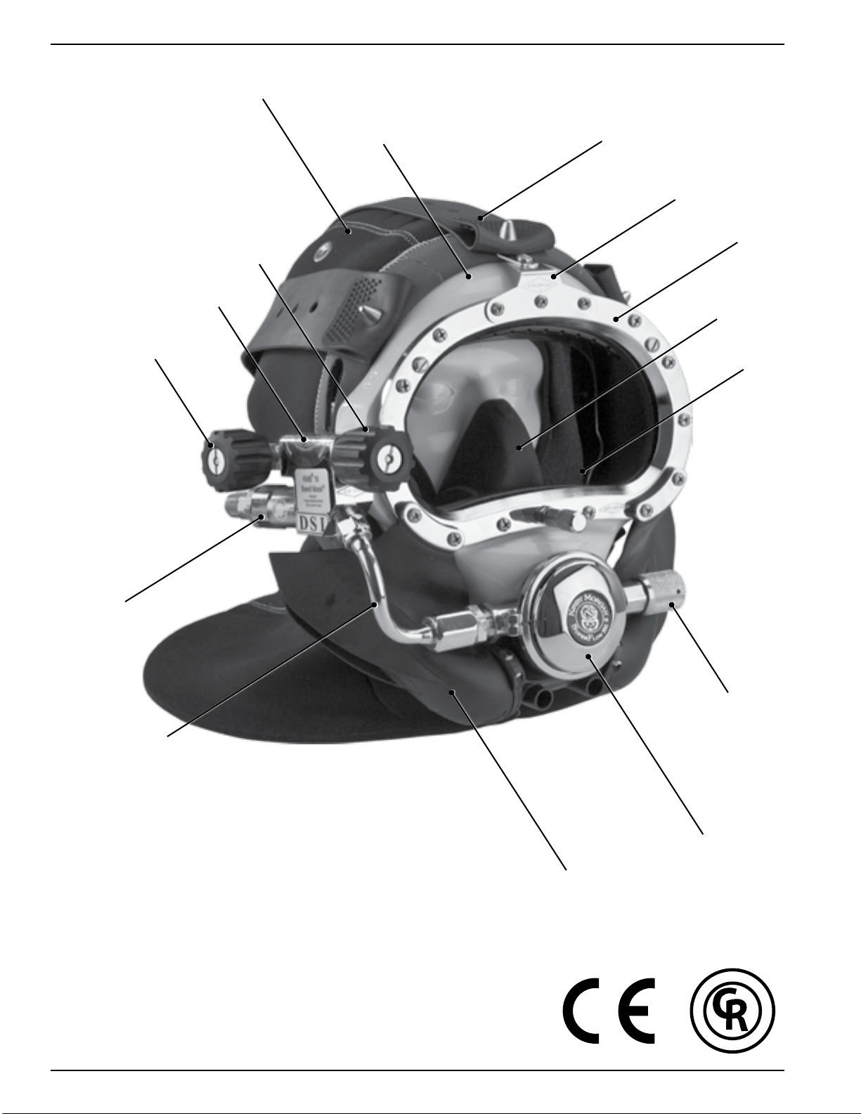
Hood
Sideblock
Emergency Gas
Supply Valve
Steady
FlowValve
Mask Frame
Spider
Band Keeper
Port Retainer
Oral/Nasal Mask
Comfort Insert
18 ONLY
Non-Return Valve
Bent Tube
The Kirby Morgan BandMask
SuperFlow 350 Regulator
Tri-Valve Whisker Wing
®
Regulator Adjustment
Knob
A
R
T
Y
E
L
D
L
A
I
-
C
R
E
M
M
O
C
D
E
T
S
E
T
B
A
P
R
O
F
E
S
S
I
O
N
A
L
D
I
V
I
N
G
L
E
G
V
E
I
A
D
R
-
™
XIV © Copyright 1970-2010 Kirby Morgan Dive Systems, Inc. All rights reserved. Document #100720002
Page 17

Kirby Morgan® BandMasks® 18 & 28
STOP!
BEFORE GOING FURTHER-
This manual will refer to location numbers in specic drawings, or in the exploded view, which is
in the back of this manual. These numbers are called “location” numbers. They are used to nd
the referred to parts in the drawings in this manual only. They are not the part number. Next to
the exploded drawing is a list of the “location” numbers that match the Kirby Morgan part numbers along with the name of the part. Always check the part number when ordering to make sure
it is correct. When ordering, always specify the helmet model number and serial number as well.
Chapter 1
General Information KMDSI Products
1.1 Introduction
The Kirby Morgan Corporation was started in 1965.
The copper and brass “Heavy Gear” or “Standard
Dress” helmets were the first helmets manufactured
by the company. Over the years Kirby Morgan designed, manufactured and sold many different helmets
and masks for commercial divers.
Staying active in commercial diving has contributed
to the successful design innovations of KMDSI products. This may be the primary reason for the acceptance of our designs by professional divers.
Bev Morgan has designed more than fifty-seven diving helmets and over 40 diving masks. All employees
of KMDSI participate as part of the Kirby Morgan
design team. It would not be possible for us to supply the commercial, military, scientific, and public
service diving industries with our equipment, without
the team of people that make up Kirby Morgan Dive
Systems, Inc. (KMDSI)
We feel it is important for the reader to understand
that we at KMDSI consider ourselves as only part
of the process along the path in diving equipment
design. We welcome all input from our customers.
The thinking of many good divers, diving equipment
engineers, diving medical specialists, diving organization administrators and their supporting personnel
has contributed to the current state of the art of diving.
Each piece of gear we manufacture has in it some of
the thinking of those who have gone before us. To
all those people who gave something of themselves
to the men and women who work underwater, we
express a thank you.
We have a strong commitment to providing the best
diving equipment and service possible. This thinking
has been the policy of Kirby Morgan Dive Systems,
Bev Morgan, Chairman of the Board
Kirby Morgan Dive Systems, Inc.
Inc. and we will continue to take this approach to
our work.
Our extensive dealer network makes it easy to obtain
genuine Kirby Morgan replacement parts, as well as
technical assistance worldwide.
KMDSI has always concentrated on designing and
manufacturing diving equipment that allows most
repairs, inspections, and all routine maintenance to
be performed by the user. Most routine preventative
and corrective maintenance can be accomplished by
the user utilizing this manual, the KMDSI Tool Kit
(P/N 525-620) and common hand tools. Technician
training is available through Dive Lab Inc. Information can be obtained on line at www.divelab.com or
by telephone at 850-235-2715.
© Copyright 1970-2010 Kirby Morgan Dive Systems, Inc. All rights reserved. Document #100720002 1
Page 18
Kirby Morgan® BandMasks® 18 & 28
C
O
M
M
E
R
C
I
A
L
L
Y
R
A
T
E
D
-
P
R
O
F
E
S
S
I
O
N
A
L
D
I
V
I
N
G
G
E
A
R
-
D
I
V
E
L
A
B
T
E
S
T
E
D
™
C
O
M
M
E
R
C
I
A
L
L
Y
R
A
T
E
D
-
P
R
O
F
E
S
S
I
O
N
A
L
D
I
V
I
N
G
G
E
A
R
-
D
I
V
E
L
A
B
T
E
S
T
E
D
™
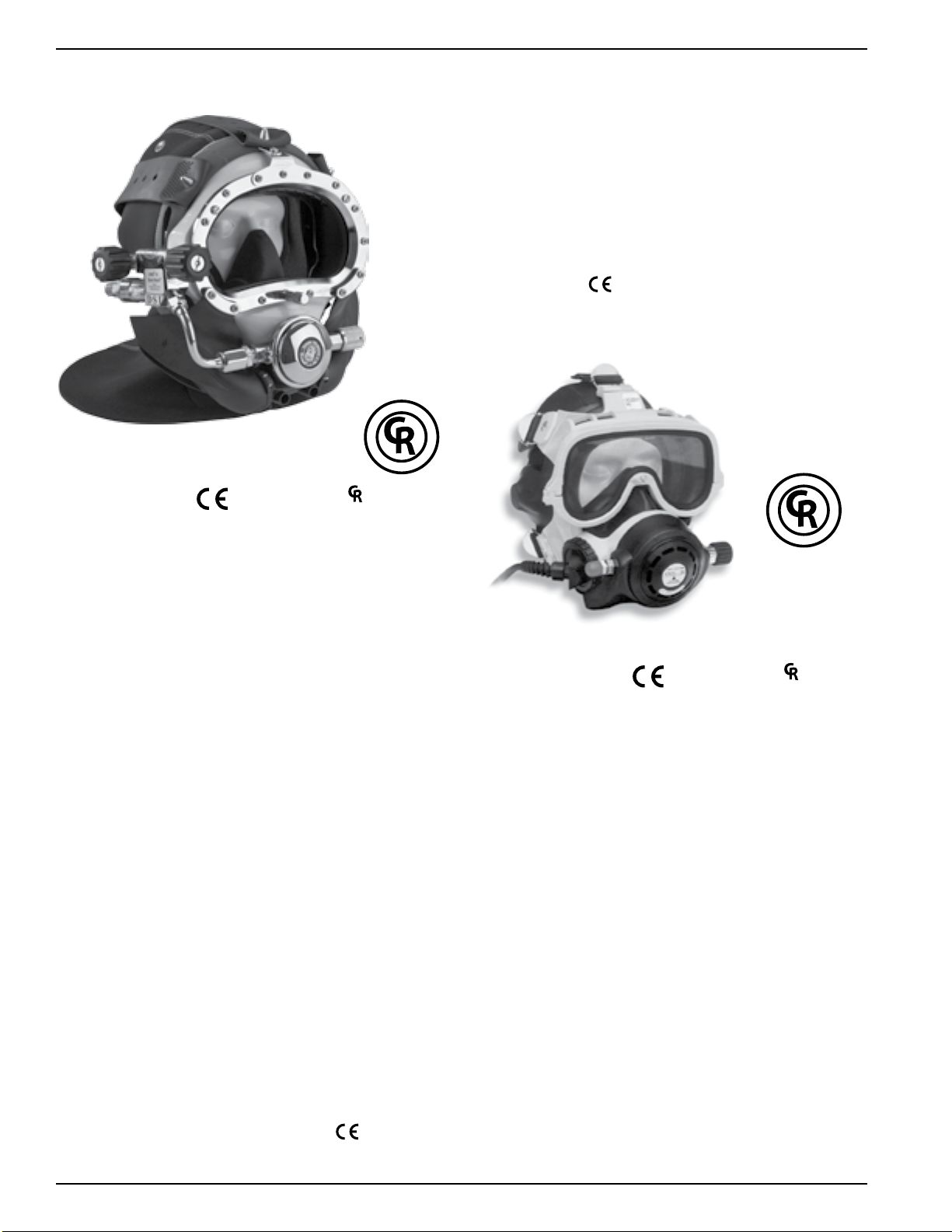
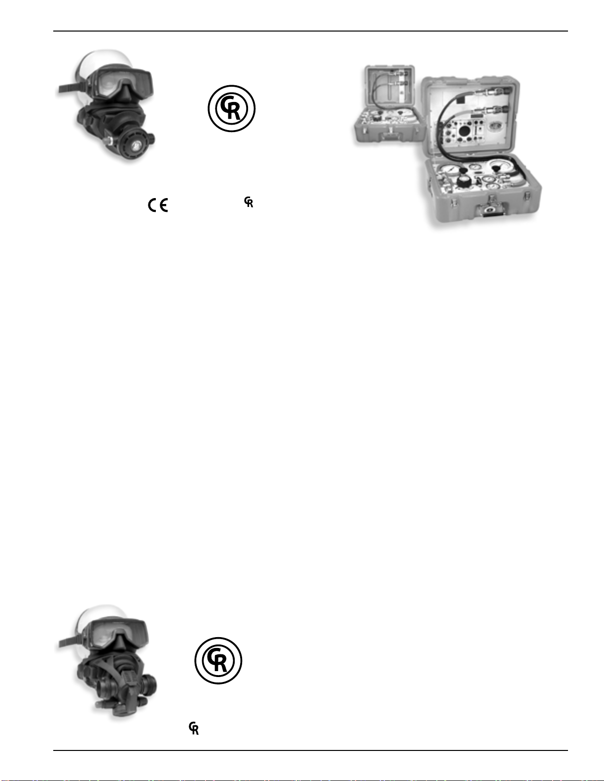
1.2 Full-Face Masks and Manifolds
KMB® 18 A/B
approved and ™ marked
The EXO Full Face Mask is designed for both
surface supplied and scuba diving. By enclosing the
divers eyes, nose and mouth, the EXO permits nearly
normal speech when used in conjunction with most
wireless, and all hard wire underwater communication systems.
The EXO BR (BALANCED REGULATOR) shown
here is designed to meet or exceed recommended
performance goals in both scuba and surface supplied
modes and is
approved. It meets and surpasses
European standards for regulator performance.
The KMB 18B BandMask® frame is constructed of
hand laid fiberglass. The head harness is a molded,
strong tear resistant neoprene rubber.
The hood, which attaches to the mask frame with
welded stainless steel bands, provides warmth for
the divers head as well as pockets for the earphones.
The communications connections can be either a male
waterproof plug in type or bare wire posts. Both this
mask and the KMB 28B feature the new Tri-Valve™
Exhaust System.
The KMB 28B BandMask
®
(not shown) is very
similar to the KMB 18, with many parts on the KMB
18B being interchangeable with the KMB 28B. The
major difference between the 18 and 28 is the material
of the mask frame itself. The KMB 18 has a fiberglass frame (yellow) while the KMB 28B frame is an
extremely durable injection molded plastic (black).
Other differences include:
1) The main exhaust body of the KMB 28 is part of
the frame itself and uses a #545-041 main exhaust
cover
2) no comfort insert is required on the 28
3) the face ports for the 18 and the 28 differ slightly
in size.
EXO® BR
approved and ™ marked
The Balanced Regulator helps reduce the work of
breathing for the diver by balancing the intermediate
air pressure against the valve sealing pressure inside
the regulator. This enables the regulator to instantly
adjust to changes in line pressure. The balanced
regulator is adjustable for a wide range of intermediate pressures between 90 PSIG – 250 over ambient
pressure (6.2 – 17 bar).
Both models have a modular communications design
that permits rapid and simple maintenance. The
optional Hard Shell provides surfaces for mounting
lights, cameras etc.
Both the KMB 18 and KMB 28 are
2 © Copyright 1970-2010 Kirby Morgan Dive Systems, Inc. All rights reserved. Document #100720002
approved.
Page 19
SuperMask M-48
C
O
M
M
E
R
C
I
A
L
L
Y
R
A
T
E
D
-
P
R
O
F
E
S
S
I
O
N
A
L
D
I
V
I
N
G
G
E
A
R
-
D
I
V
E
L
A
B
T
E
S
T
E
D
™
C
O
M
M
E
R
C
I
A
L
L
Y
R
A
T
E
D
-
P
R
O
F
E
S
S
I
O
N
A
L
D
I
V
I
N
G
G
E
A
R
-
D
I
V
E
L
A
B
T
E
S
T
E
D
™
™
w/ Scuba Pod
Kirby Morgan® BandMasks® 18 & 28
KMACS-5
w/ No Communications
approved and ™ marked
The SuperMask M-48 is an innovative new design
in a full-face mask. It provides the diver with all the
comfort of a full-face mask with the convenience
of changeable second stage regulators as well as the
ability to use a snorkel without having to remove
the mask.
The mask is comprised of two major components,
the mask frame and the interchangeable lower pod.
The removable lower pod is a feature unique to the
SuperMask full-face mask. When diving, the pod is
easily removed and replaced on the mask, providing
the diver the capability to buddy-breathe, snorkel,
use an octopus or perform an “in water” gas switch.
With the pod sealed to the mask, the flexible, silicone
pod cover allows the diver to quickly place the regulator mouthpiece into the mouth or dive with it free of
the mouth for communications. With the mouthpiece
in, the regulator may be used without the pod being
sealed to the mask.
KMACS-5
w/ Communications
The Kirby Morgan Air Control System-5 (KMACS)
is a lightweight, portable control box for use in surface supplied air diving operations. The KMACS-5
controls the diver’s air supply, communications and
monitors the diver’s depth. It allows two divers clear
push-to-talk (two wire) or round robin (four wire)
communications. The KMACS-5 is also available
without communications.
The air supply can be either from a low-pressure
compressor or high-pressure cylinders. The adjustable first stage regulator reduces the high-pressure
air and supplies low pressure through the umbilical
to the diver’s breathing system.
High pressure yokes permit U.S. standard scuba
cylinders or DIN equipped cylinders to be used. Lowpressure air supply fittings allow for a compressor to
be used as the primary air source.
The mask may also be used surface supplied when
used with the proper accessories. We are currently
developing several different pod configurations for
both open circuit and rebreather use. For further
information, see the Frequently Asked Questions
(FAQ) area on
our web site at www.KirbyMorgan.
com/FullFaceMasks/M48.html.
A complete pneumo system with dual reading gauges
(both US Standard and Metric) is provided for each
diver’s air, as well as a shut-off/bleed system that uses
two high-pressure feed lines which allows changing
of used cylinders without interruption of the diving
operation. Optional shut off valves allow the isolation
of each diver’s air supply.
The Communication Set is a multipurpose intercommunication system that provides reliable and clear
communications between a topside operator (tender)
and one or more surface-supported divers, recompression chambers, or other submersible systems.
© Copyright 1970-2010 Kirby Morgan Dive Systems, Inc. All rights reserved. Document #100720002 3
SuperMask M-48
w/ Rebreather pod
marked
Page 20
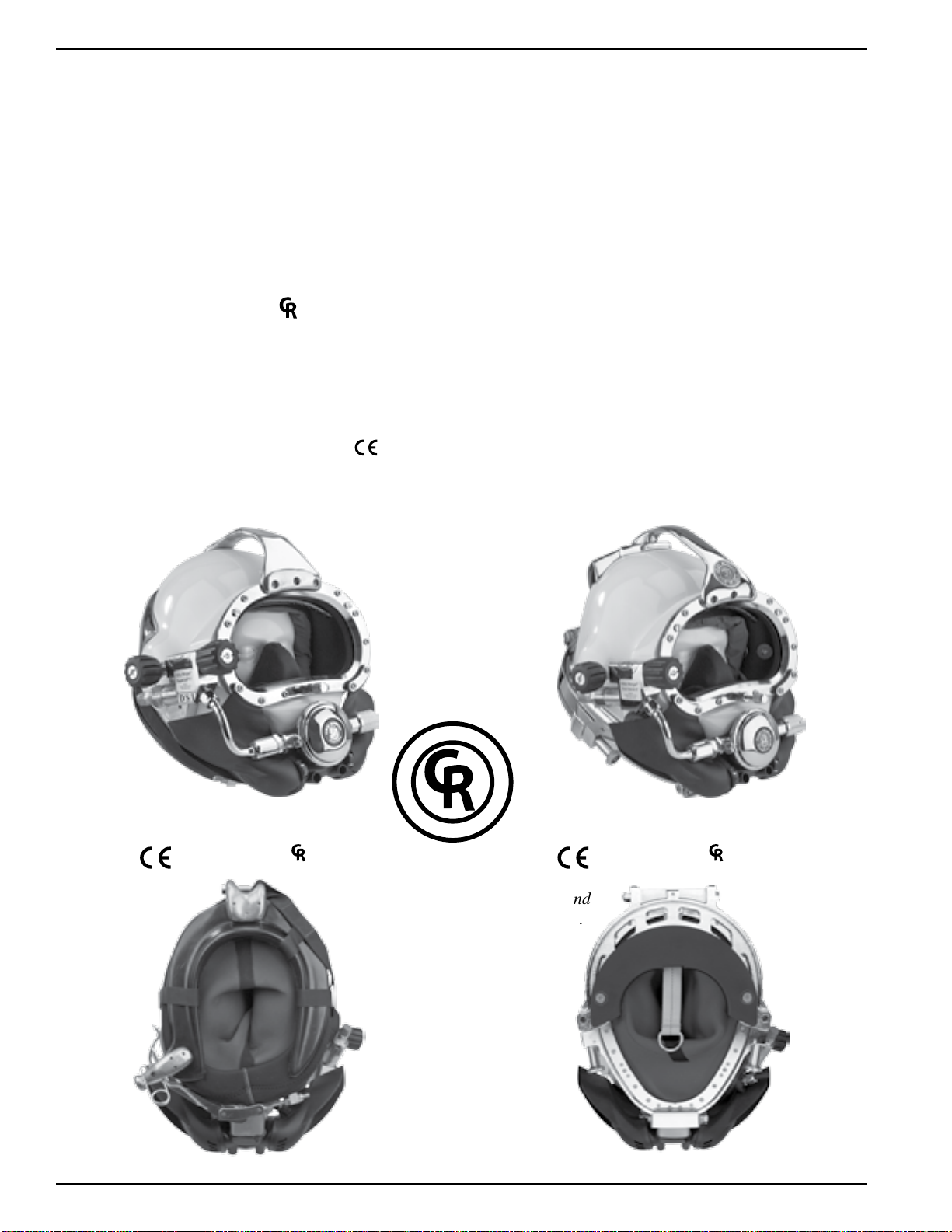
Kirby Morgan® BandMasks® 18 & 28
1.3 Kirby Morgan Diving Helmets
All Kirby Morgan diving helmets and masks are
manufactured by Kirby Morgan Dive Systems, Inc.
(KMDSI). Each step of the manufacturing process is
carefully controlled to assure the customer of a high
quality, durable helmet that will function properly
for many years.
There are eight models of Kirby Morgan diving helmets currently in production. They are the SuperLite
17B, (MK-21- U.S. Navy version), SuperLite
the SuperLite
37SS, 47, 57, and 77. All are
The SuperLite
®
27, and Kirby Morgan models 37,
®
-17 A/B was first developed in 1975
™
marked.
and quickly set a new standard for diving helmet
design. Many large and small commercial diving
companies, military organizations, scientific divers,
and public safety divers are successfully using this
design around the world. This helmet is
marked.
®
17C
®
The SL-17 A/B helmet system consists primarily of
two major components: the neck dam/yoke assembly,
and the helmet. To don the helmet, the diver first
slips the angled neck dam with the attached yoke over
their head. The helmet is lowered onto the diver’s
head with the help of a tender, then the yoke hinge
tab is hooked onto the alignment screw on the rear
weight. The neck clamp is then slipped onto the helmet and locked. The locking system not only seals
-
the neck dam to the helmet but also secures the front
of the yoke, fastening the helmet to the diver’s head.
The SuperLite
®
-17A/B shares many common breath-
ing system parts with all Kirby Morgan helmets and
masks. The breathing system was man-tested to
1600 FSW by the University of Pennsylvania and
approved by the U.S. Navy for surface-supplied diving to 190 FSW with air and 300 FSW with mixed
gas. It surpasses all requirements of all governing
agencies and it is approved for commercial diving
through out the world.
SuperLite® 17A/B
approved and ™ marked approved and ™ marked
Yoke and Latch Catch
Assembly
A
R
T
Y
E
L
D
L
A
I
C
R
E
M
M
O
C
D
E
T
S
E
T
B
A
L
E
-
P
R
O
F
E
S
S
I
O
N
A
L
D
I
V
I
N
G
G
V
E
I
A
D
R
-
™
Kirby Morgan
®
37
Neck Pad and
Sealed Pull Pins.
4 © Copyright 1970-2010 Kirby Morgan Dive Systems, Inc. All rights reserved. Document #100720002
Page 21
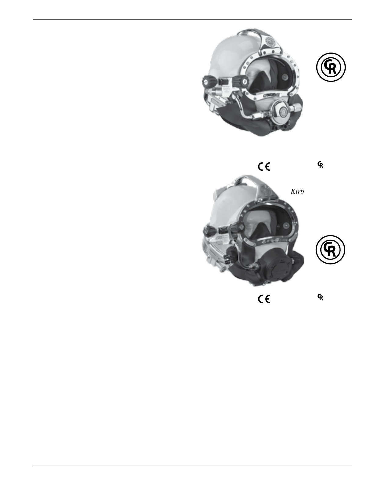
Other features that are common to all Kirby Morgan
C
O
M
M
E
R
C
I
A
L
L
Y
R
A
T
E
D
-
P
R
O
F
E
S
S
I
O
N
A
L
D
I
V
I
N
G
G
E
A
R
-
D
I
V
E
L
A
B
T
E
S
T
E
D
™
C
O
M
M
E
R
C
I
A
L
L
Y
R
A
T
E
D
-
P
R
O
F
E
S
S
I
O
N
A
L
D
I
V
I
N
G
G
E
A
R
-
D
I
V
E
L
A
B
T
E
S
T
E
D
™
helmets include:
* Face port and retainer ring
* Communications components
* Oral/nasal mask
* Nose block device
* Air train defogger
Kirby Morgan® BandMasks® 18 & 28
The Kirby Morgan
®
37 Commercial Diver’s Helmet
represents what we at Kirby Morgan consider to be
a turning point in modern diving helmet design. The
helmet consists of two major assemblies: the helmet
shell/helmet ring assembly and the neck dam/neck
ring assembly.
The helmet comes with the large tube SuperFlow
350 adjustable demand regulator which provides an
easier breathing gas flow during peak work output.
A quick change communications module is available
with either bare wire posts or a waterproof connector.
The helmet ring houses the sealed pull pins and provides protection for the bottom end of the helmet. The
diver is also provided with an internally adjustable
chin support. This custom fit and balance seats the
helmet comfortably for long periods of time even
when working in the face down position.
The SuperLite
®
27® Commercial Diver’s Helmet has
all the same features of the KM37 on a smaller, low
volume shell design. This helmet is often preferred
by persons with smaller heads.
SuperLite
approved and ™ marked
®
®
27
Kirby Morgan® 47
®
The chrome plated machined brass helmet neck ring
houses the sealed pull pins and provides protection
for the bottom end of the helmet. Like the SL-17K,
37 and 17C, the diver is provided with an internally
adjustable chin support. This support, along with the
adjustable neck pad on the locking collar, gives the
diver a comfortable, secure, custom fit.
The quick-change communications module, available
The Kirby Morgan® 47 offers the ultimate in a high
performance breathing regulator. This helmet has an
entirely new breathing system, oral nasal mask, and
water ejection system. The REX
with it’s fully adjustable balanced piston is a breakthrough design that exceeds the requirements of all
government or other testing agencies.
approved and ™ marked
®
Demand Valve,
with either bare wire posts or a waterproof connector,
allows for easy, efficient maintenance of the helmets
communications.
It has the best work-of-breathing performance when
compared to ANY other commercial diving helmet.
The Kirby Morgan 47 Dive Helmet has been tested
The helmet also features the SuperFlow 350 large
tube adjustable demand regulator. The helmet is
available in the umbilical over the shoulder, “B”
and meets or exceeds European CE requirements and
is fully commercially rated. In all other respects, this
helmet is nearly identical to the Kirby Morgan 37.
configuration only.
© Copyright 1970-2010 Kirby Morgan Dive Systems, Inc. All rights reserved. Document #100720002 5
Page 22
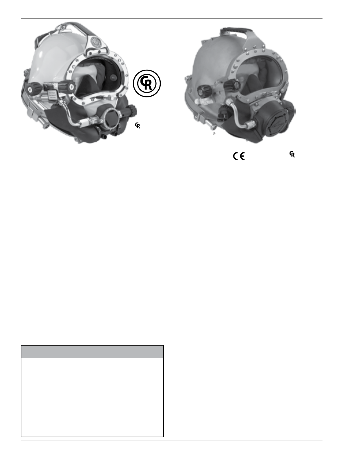
Kirby Morgan® BandMasks® 18 & 28
C
O
M
M
E
R
C
I
A
L
L
Y
R
A
T
E
D
-
P
R
O
F
E
S
S
I
O
N
A
L
D
I
V
I
N
G
G
E
A
R
-
D
I
V
E
L
A
B
T
E
S
T
E
D
™
®
™
marked
®
The Kirby Morgan® 57 helmet features our revolutionary new SuperFlow 450 Stainless Balanced
Regulator. It's machined from a stainless steel casting
for the ultimate in performance and reliability.
Like all KMDSI regulators on our helmets and Band
Masks
®
, we use only regulators that are specifically
designed for surface-supplied diving, that will perform over the wide range of pressures delivered
by low pressure compressors. An ordinary SCUBA
regulator mounted on a diving helmet is not capable
of delivering the gas you need at heavy work loads.
This commercially rated fully diver adjustable regulator delivers all the breathing gas you might require
for the most demanding work underwater.
The Kirby Morgan
®
57 also includes our Quad-
Valve™ Exhaust System. It's recommended for diving in biologically contaminated water, when you're
properly trained and equipped, using recommended
procedures. This new exhaust has exceptionally low
exhalation resistance that you must experience to
appreciate.
approved and ™ marked
The Kirby Morgan® 77 represents the first in a new
generation of stainless steel diving helmets that provide an alternative for the diver who prefers a metal
helmet. The helmet features our new stainless steel
®
REX
regulator, which offers the best performance
of any other Kirby Morgan system.
It has the best work-of-breathing performance when
compared to ANY other commercial diving helmet.
The Kirby Morgan 77 Dive Helmet has been tested
and meets or exceeds European CE requirements and
is fully commercially rated.
The advantages of this all stainless steel helmet include the following:
• No refinishing required if the surface is scratched
or gouged.
• Faster production of helmets for customer delivery.
• Elimination of threaded inserts for securing the port
retainer to the helmet shell.
B WARNING
• No need to remove the handle to remove the port
retainer.
Before attempting any diving in any
type of contaminated water, a complete diving and topside course in
hazardous materials emergencies
• One piece sideblock includes both the free-flow
valve and the Emergency Gas System valve.
should be completed. The divers and
the topside team must be properly
• The helmet ring is an integral part of the helmet.
trained and have the proper safety
equipment. All helmets and suits can
leak water under certain conditions.
Divers should use extreme caution
when diving in contaminated waters.
6 © Copyright 1970-2010 Kirby Morgan Dive Systems, Inc. All rights reserved. Document #100720002
Page 23
Kirby Morgan® BandMasks® 18 & 28
®
approved and ™ marked
The Kirby Morgan
®
37SS features an all stainless
steel shell, as well as a stainless sideblock, helmet
ring, bent tube, handle, and other key components.
The SuperFlow 350 is standard on this helmet.
The Kirby Morgan 37SS features a quick change
communications module, available with either bare
wire posts or a waterproof connector, and allows
for easy, efficient maintenance of the helmet's communications.
The advantages of this stainless steel helmet include
the following:
• Rugged helmet shell and other components
• No refinishing required if the surface is scratched
or gouged
• Elimination of threaded inserts for securing port
retainer to helmet shell
© Copyright 1970-2010 Kirby Morgan Dive Systems, Inc. All rights reserved. Document #100720002 7
Page 24

Page 25
Kirby Morgan® BandMasks® 18 & 28
WARNING
WARNING
Chapter 2
Description & Operational Specications
Kirby Morgan 18 & 28
This manual is our effort to explain the operation, maintenance and use of the KMB 18 & 28. We
do not herein make any effort to teach the principles of diving. It is our assumption the reader is
a qualied diver. We highly recommend that all divers should train, under controlled conditions,
in the use of any model of commercial diving mask that they have not previously used or trained
in, prior to use on the job, until they have mastered the skills required to use their mask correctly.
This section includes detailed descriptions of the
Kirby Morgan 18 and 28, as well as important operational specifications. Most, but not all, parts are
interchangeable between these two masks.
2.1 Product Specications
Weight: KMB 18 - 13.63 pounds
KMB 28 - 12.73 pounds
Mask Frame KMB 18: Fiberglass, polyester resin,
polyester gel coat, carbon fiber
Mask Frame KMB 28: Xenoy
Control Knobs: ABS plastic
Lens: Clear polycarbonate
Hood: Neoprene.
O-Rings: Buna-N
The recommended lubrication type for breathing
gas mixtures containing oxygen percentages greater
than 50% is Christo Lube
Halocarbon
®
. Helmet gas train components being
used with gas mixtures containing less than 50%
oxygen can be lubricated with food grade silicone
grease such as Dow Corning
can be used in waters at water temperatures as low
as 34° F (1°C).
®
thermoplastic
®
, Krytox®, Tribolube® and
®
111. The BandMask®
2.2 Regulator Performance
2.2.1 SuperFlow® and SuperFlow® 350
Demand Regulators
The SuperFlow 350 non balanced regulator is the
standard demand regulator found on the SL-27,
KM-37 and KMB 18/28 BandMasks
®
. NOTE: Pre
Sep. 2004 KMB 28 plastic frames will only except
the smaller mount tube found on the SuperFlow
(non 350) regulator. The SuperFlow 350 is fully CE
marked and CR rated. The SuperFlow 450 SS balanced regulator can be used on the SL-27, KM-37 and
KMB-18/28 BandMasks
®
. Breathing performance is
greatly affected by the support equipment used, as
well as the supply pressure to the helmet or mask.
2.2.2 SuperFlow® 450 Performance
The SuperFlow
®
450 is an all Stainless Steel regulator of a balanced design that offers a slightly higher
degree of breathing performance and extreme breathing rates, more than the non balanced SuperFlow
regulator.
2.3 Cage Code
The cage code for identifying KMDSI products for
U.S. government purposes is 58366.
2.4 CR Standards
Never use aerosol-propelled sprays near the
face port of any Kirby Morgan diving mask.
The propellant used in these aerosols can
invisibly damage the face port and cause it
to shatter on impact from any strong blow. If
the face port fails underwater, injury or death
may result.
If you have any questions regarding proper set-up,
operation, or maintenance of your Kirby Morgan 18
or 28, contact KMDSI (850) 928-7772 or at kmdsi@
KirbyMorgan.com or Dive Lab Inc. (850) 235-2715
or at Divelab@aol.com
© Copyright 1970-2010 Kirby Morgan Dive Systems, Inc. All rights reserved. Document #100720002 9
Kirby Morgan masks and helmets meet or exceed all
standards established by Dive Lab of Panama City,
Florida, and are CR (Commercially Rated) marked.
Page 26
Kirby Morgan® BandMasks® 18 & 28
2.5 CE Certication
The BandMask® has been tested and conforms to the
performance requirements as set forth in Annex II of
Directive 89/686/EEC and, as far as applicable, the
EN 250:2000, EN 250/A1:2006 and EN 153331:2008 (Class C). It is fully CE marked with demand
regulator SuperFlow
690 and P/N 510-747.
®
350 and oral nasals P/N 510-
CAUTION
The user cannot:
• remove the mark from the frame of
the BandMask®;
• modify or counterfeit the data reported on the mark.
Category of PPE: III
WARNING
The BandMask® has been tested with
air and CE certicates for use with air
up to 50 meters. Compressed air must
been compliant with the EN 12021.
All the tables reporting the technical
data and the pressure of use are relative to compressed air.
2.5.1 CE Marking
On the frame of the BandMask
fixed.
EN250:2000
EN250/A1:2006
EN15333-1:2008
CLASS C
BAND MASK MODEL:
YEAR OF PRODUCTION:
CE Mark
In the mark the data reported are the following:
®
the CE mark is af-
KIRBY MORGAN
DIVE SYSTEMS, INC.
1430 Jason Way,
Santa Maria, CA 93455
0496
CAUTION
The mark must be visible and legible
throughout the life of the PPE. If the
mark deteriorates or is not legible
the user should contact the manufacturer.
2.5.2 Notifying Body
The Notified Body is DNV- MODULO UNO S.c.a.r.l.
Address: Via Courgnè, n.21
10156 Torino
Identification number: 0496.
2.6 Risks in Decompression Diving
Decompression diving always presents the diver with
additional risks.
WARNING
Decompression diving always involves
the risk of decompression sickness.
Omitted decompression due to a loss
of the breathing gas supply or other
accidents can cause serious injury or
death. Use of a Kirby Morgan mask
or helmet cannot prevent this type of
injury.
1. The name and the address of the manufacturer;
2. Harmonized reference standard: EN 250:2000,
EN 250/A1:2006 and EN 15333-1;
2.7 Operational Specications & Limitations
-Umbilical minimum I.D. 3/8” (9.5 mm) of not more
than two sections, total length not to exceed 600 feet
3. CLASS C = NO protection;
4. PPE model;
5. Serial number (stamp on the BandMask
6. The year of production;
7. CE marking:
;
8. Notifying Body number
®
frame);
(183m).
The KMB 18 and 28 meet or exceed all requirements
of NPD, Health and Safety, (U.K.), United States
Navy, ADCI United States and is CR rated by Dive
Lab, Panama City, Fla., USA.
Every model of KMDSI helmets and masks undergo
extensive type testing to fully document the performance capability and required supply pressures when
using various umbilical and pressure combinations.
All users should take the time to become knowledgeable on supply requirements to insure proper performance and for the comfort and safety of the diver.
10 © Copyright 1970-2010 Kirby Morgan Dive Systems, Inc. All rights reserved. Document #100720002
Page 27
Kirby Morgan® BandMasks® 18 & 28
Recommended overbottom (OB)gas supply pressure
for best performance at depths are calculated by the
formula (fsw x 0.445) + recommended p.s.i g.
The required supply pressures for the KMB 18 and
28 equipped with either the SuperFlow
SuperFlow
®
450 regulators are listed in the appropri-
®
350 or
ate supply pressure tables in Appendix 3.
WARNING
The demand regulator
and side block assemblies have a maximum
design pressure of 250
psig (15.5 bar) over the
ambient pressure, higher
pressures could lead to
component failure resulting in serious injury.
The supply pressures listed in the supply tables were
derived by breathing simulator trials. There are two
tables used for the SuperFlow
regulators and two separate tables for the SuperFlow
®
and SuperFlow® 350
®
450 regulator. It is important that users understand
how to use the tables. For further information on
supply requirements for the KMB 18 and 28 or any
Kirby Morgan helmet or mask check the Kirby Morgan website at www.kirbymorgan.com.
WARNING
When the BandMask®
is used for air diving in
countries that conform
to C.E. regulations it
must be used to a maximum depth of 164fsw
(50msw). I.A.W. EN
15333-1.
-Temperature limitations: Use at water temperatures
below 33 ºF (1 ºC) requires use of hot water shroud
(P/N 525-100) and hot water.
NOTE The Hot Water Shroud (Part #525-100) in
conjunction with hot water to the diver should be
used whenever diving operations are conducted
using HEO
(15.56°C) for the comfort of the diver.
KMDSI further recommends that the shroud
be used in conjunction with hot water to the diver
whenever diving operations are conducted using air
or mixed gas, in waters colder than 33°F (1°C) to
reduce the possibility of demand regulator icing.
at water temperatures less than 60°F
2
NOTE: Usually the greatest danger of demand
regulator icing will be encountered on deck when
the surrounding air temperature is less than 32°F
(0°C). This effect is primarily due to the refrigeration effect of breathing air pressure reduction, and
the addition of moisture from the divers exhalation
coming in contact with the topside air temperature.
If diving where the water temperature is 33°F
(1°C) or warmer but the topside air temperature
is below freezing, 32°F (0°C) icing of the demand
regulator is possible. To help eliminate the possibility of freezing on the surface, warm water should be
run over the exterior of the demand regulator prior
to water entry, if the hot water system is not used.
The umbilical assembly should be composed of good
quality diving hose that meets industry standards.
Generally, gas hose will be married to the communications wire, pneumofathometer hose, and strength
member in a manner that will allow the strength
member to receive all the strain. There are also good
quality umbilicals available that are assembled at
the factory using a twisted method which does not
require marrying. Regardless of the system used, the
umbilical is the diver’s life line and should always be
of excellent quality and maintained carefully.
If you have any questions regarding proper set-up,
operation, or maintenance of your KMB 18 or 28
contact KMDSI (850) 928-7772 or at kmdsi@KirbyMorgan.com or Dive Lab Inc. (850) 235-2715 or
at Divelab@aol.com
WARNING
Gas systems used to supply Kirby
Morgan helmets and masks must
be capable of supplying gas to the
diver at the required pressure and
ow rates as stated in the operational
specications. The use of unregulated
gas sources is extremely dangerous.
The use of standard SCUBA type
regulators is unacceptable, as there
are no provisions for adjusting the intermediate pressure to the diver. Only
proven systems that allow for varying
the gas supply pressure to the diver
should be used for umbilical diving.
© Copyright 1970-2010 Kirby Morgan Dive Systems, Inc. All rights reserved. Document #100720002 11
Page 28
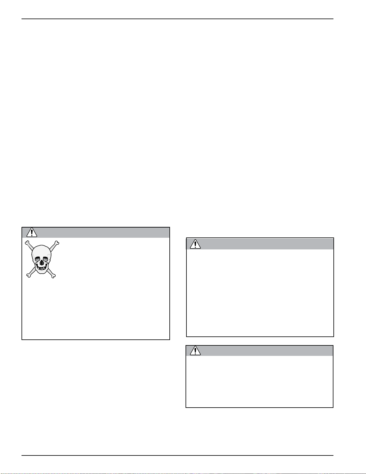
Kirby Morgan® BandMasks® 18 & 28
WARNING
WARNING
WARNING
2.8 Overview of the KMB18 & KMB28
All Kirby Morgan diving masks are manufactured by
hand. Each step of the manufacturing process is carefully controlled to assure the customer a high quality,
durable mask that will function properly.
The mask is a rugged full-face mask that was specifically designed for commercial diving to allow a
working diver to swim as easily as possible.
These masks feature the SuperFlow 350 large tube
adjustable demand regulator which provides superb
breathing gas flow during peak work output.
Both the KMB 18 and 28 are configured to receive
the umbilical over the shoulder.
Both masks use the Tri-Valve™ Exhaust system to
provide an exceptionally dry breathing regulator.
However, these masks are not recommended for con-
taminated water diving. Hooded face masks should
NOT be used for diving in contaminated water situations. Water can leak past the face seal and expose
the diver to contaminants.
The Kirby Morgan BandMask
Morgan BandMask® KMB 28 compare as follows:
1) The face port (or view port) on the KMB 18 remains
unchanged in shape from the SuperLite®-17A/B. The
face port in the KMB 28 is a slightly different size
than the KMB 18.
2) The main exhaust body is molded into the mask
frame in the KMB 28.
3) The exhaust covers on the two masks are slightly
different.
4) There is a vacuum formed comfort insert in the
KMB 18.
5) The air train in the KMB 28 requires a special
standoff for proper mounting of the side block.
6) The side block and bent tube assembly that transports air/gas to the demand regulator from the side
block are the same on both masks and on most Kirby
Morgan helmets.
®
KMB 18 and the Kirby
Before attempting any diving
in any type of contaminated
water, a complete diving and
topside course in hazardous materials emergencies
should be completed. The divers and the
topside team must be properly trained
and have the proper safety equipment. All
helmets and suits can leak water under
certain conditions. Divers should use
extreme caution when diving in contaminated waters.
The Tri-Valve™ exhaust works well during jetting
operations. It has been found that the use of a TriValve™ assembly can help in the prevention of
inversion of the exhaust valve during heavy jetting
operations.
Communications are available in either bare wire
posts or with a waterproof connector, and allows for
easy, efficient maintenance of the communications in
the mask. The KMB 18 and 28 incorporate the same
communications components used in all other Kirby
Morgan helmets.
The face ports for the KMB 18 and KMB
28 are not interchangeable. Do not attempt to use a face port from a KMB 28
in a KMB 18.
Although the port will t into the mask
frame, it will not seal properly. This will
lead to continuous leakage of the mask
and could cause a rapid depletion of the
diver’s breathing gas as they attempt to
clear the mask.
Never use a third party face port. Its
thickness or shape may be incorrect and
cause it to ood. It could also be made of
inferior materials causing it to fail. This
could be fatal.
12 © Copyright 1970-2010 Kirby Morgan Dive Systems, Inc. All rights reserved. Document #100720002
Page 29

When diving in heavy current (i.e. exceed-
CAUTION
ing 3 knots) the single exhaust system
on all KMDSI masks/helmets could allow
water to enter, due to turbulence/eddying.
It is important for the user/diver to take
excessive currents into consideration.
The Tri-Valve Exhaust
®
system will help
prevent water intrusion when diving in
heavy currents, up to 5 knots. Unlike the
old double exhaust, the Tri-Valve does
not limit the diving depth.
Many of the breathing system components on these
masks are also compatible with the Kirby Morgan
helmets. This helps reduce the inventory of spare parts
that must be carried by commercial diving companies.
Kirby Morgan® BandMasks® 18 & 28
© Copyright 1970-2010 Kirby Morgan Dive Systems, Inc. All rights reserved. Document #100720002 13
Page 30
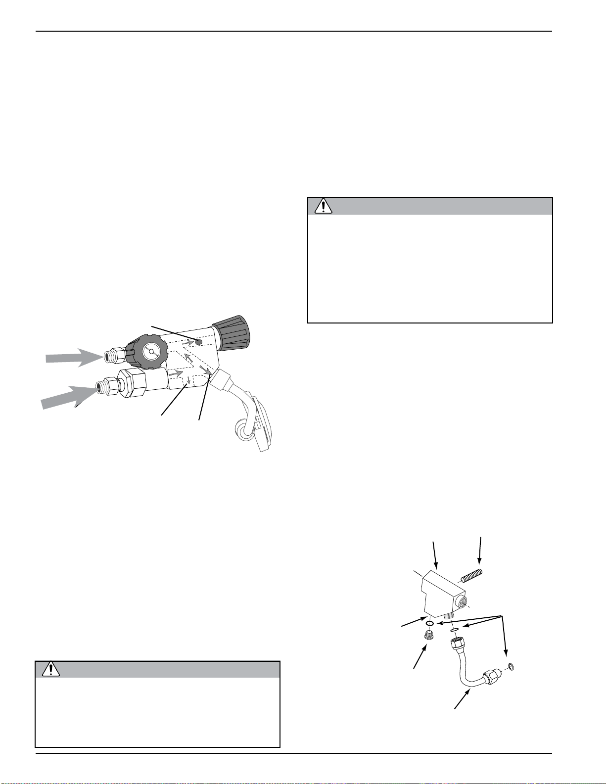
Kirby Morgan® BandMasks® 18 & 28
WARNING
WARNING
2.9 Detailed Description
2.9.1 Mask Frame
The mask frame on the KMB 18 is fabricated of
noncorrosive, rigid fiberglass which will not carry an
electrical charge. The mask frame on the KMB 28
is made from Xenoy
not carry an electrical charge.
The mask frame is the central structure for mounting
all the components that make up the complete mask.
It is designed to allow easy replacement of parts when
necessary. Any repair to the mask frame must be done
at an approved KMDSI repair center.
2.9.2 Gas Flow Systems
The main gas supply flow from the umbilical enters
the system at the adapter and flows through the one
way valve to the interior of the side block . The
one way valve or “non-return” is a very important
component.
EGS
Gas Supply
Main Gas
Supply
®
, a thermoplastic that also will
Gas Flow To Air Train
The emergency gas comes from a tank of compressed
gas worn by the diver. It enters the system through
the Emergency Gas valve when the diver turns the
control knob on. The flow then enters the side block .
Both sources of gas flow through the same passage in
the side block body to three exits. One exit is always
open to supply gas to the demand regulator assembly .
The second exit is to the defogger valve (also known
as the free-flow or steady-flow valve) assembly. The
third is to the port on the side block to connect a dry
suit inflator hose.
Never connect the main gas supply hose
from the diving station/umbilical to the
emergency valve. There is no one way
valve in the emergency gas valve. If this
mistake is made, any break in the supply
hose could possibly result in a “squeeze”.
This could result in serious injury or
death.
The side block on the mask is drilled and tapped to accept low-pressure inflator hoses. This allows the diver
the capability to inflate variable volume dry suits. It
is tapped with a 3/8-24 thread orifice, standard for
American first stage scuba regulator’s low-pressure
auxiliary fittings.
Auxiliary L.P. Port
Gas Flow
To Regulator
The one way valve prevents the flow of gas out of
the helmet to the umbilical in the event of a sudden
lowering of pressure in the umbilical. This can happen due to an accidental break in the hose or a fitting
near the surface. Not only would the emergency gas
be lost if the one way valve failed (concurrent with
a hose or fitting break on deck), but the diver could
suffer from a serious “squeeze” that could cause
injury or death.
Although we have selected the valve for its reliability and quality, inspection and maintenance of
this valve must be done regularly. It is very easy to
disassemble and inspect. (A rebuild kit for this valve
is Part #525-330).
The one way valve must be tested daily, prior
to the commencement of diving operations.
Failure of one way valve could cause serious
injury or death. Follow the procedures for
testing the valve in this manual.
The port is shipped plugged at delivery. This inflation capability does not significantly interfere in any
way with the breathing characteristics of the regulator
during normal use providing a limiting hose is used.
When using a dry suit inflation hose, the hose should
be equipped with a flow restrictor (P/N 555-210) to
limit flow in the event the hose ruptures or is severed.
Side block
Install inflator
hose here
Plug
Bent tube
Low pressure hoses may be connected to the side block.
Stud
O-ring
14 © Copyright 1970-2010 Kirby Morgan Dive Systems, Inc. All rights reserved. Document #100720002
Page 31

WARNING
The side block inator port is intended
WARNING
for dry suits only. When using the side
block low-pressure inflator port, only
good quality hoses and ttings should be
used and must incorporate an in-line ow
restrictor to reduce gas ow in the event
of hose failure. Any hose or tting failure
in this arrangement will subject the diver
to a decreased air supply. Do not use the
side block inator port for any purpose
other than attaching a dry suit hose.
The KMDSI Restrictor Adaptor,
KMDSI Part #555-210.
When using the side block low pressure
inator port, the diver should only use
high quality hoses with an integrated ow
restrictor or a KMDSI ow restrictor PN#
555-210. All hoses must have an in-line
restrictor to reduce the gas ow in the
event of hose failure.
Do not use fitting adapters. Standard
adapters do not provide an adequate ow
restriction. The use of many off-the- shelf
adapters on the side block assembly
could expose the low pressure hose ttings to excessive stress. Any failure of
an ination hose will subject the diver to
a decreased supply pressure.
Kirby Morgan® BandMasks® 18 & 28
The diver can control the flow of gas through the
defogger system with the control knob for either
emergency breathing (backups) or to flush water that
may have entered the mask. The gas enters the mask
and flows through the air train which directs the gas
onto the face port to help eliminate or clear fogging
that forms on the port from the diver’s warm breath.
The gas flow continues out through the water dump
(main exhaust) valve, or into the oral nasal mask by
means of the oral/nasal valve. The diver can breathe
from this flow of gas if the demand regulator malfunctions. The gas then flows through the oral nasal
valve, through the oral nasal, into the regulator and
out through the regulator exhaust. Flow continues
into the exhaust main body of the Tri-Valve
™
exhaust.
From there it can exit through either of the exhaust
valves and out through the whiskers.
With normal breathing as the diver inhales the helmet and demand regulator body go slightly negative
drawing the diaphragm down against the roller lever
opening the inlet valve and starting gas flow. The gas
flow continues to match the diver’s inhalation as the
rate increases, peaks and then ebbs and stops when
the diver exhales. The supply gas stays off as the
exhalation gas passes out through the exhaust valves
and Tri-valve whisker into the water. The Tri-Valve
whisker helps deflect the bubbles away from the face
port to keep the view clear.
Adjustment Knob
Adjustment
Shaft
O-ring
Retaining Pin
Spacer
Regulator Body
The SuperFlow 350 Demand Regulator
Inlet Valve
O-ring
Inlet Nipple
Jam Nut
Exhaust Valve
© Copyright 1970-2010 Kirby Morgan Dive Systems, Inc. All rights reserved. Document #100720002 15
Gasket
Screws
Exhaust
Flange
Piston
Spacer
Roller Lever
Washer
Diaphragm
Nut
Cover
Washer
Spring Set
Retaining Clip
Purge Button Spring
Packing Nut
Screw
Clamp
Purge Button
Sticker
Purge Button
Page 32

Kirby Morgan® BandMasks® 18 & 28
WARNING
flange
Diving a KMDSI helmet or BandMask®
with a bias setting greater than that just
necessary to keep the demand valve
from free owing increases the work of
breathing and reduces the diver’s ability
to perform heavy work.
All KMDSI Helmets and BandMasks® are equipped
with a multi-turn demand regulator adjustment knob.
This adjustment knob allows the diver to make corrections to compensate for a wide range of incoming
gas supply pressures.
The adjustment knob operates by simply increasing
or decreasing the amount of spring bias tension on the
demand regulator inlet valve. The adjustment knob
has a range of approximately 13 turns from full in
to full out. The intent of this bias adjustment device
is strictly to allow the diver to make adjustments for
variations in umbilical supply pressure.
be adjusted by the diver to be at the easiest breathing setting at all times. The exact number of turns
required is dependent on the supply pressure.
The Tri-Valve exhaust system is now standard equipment for the KM 18 and 28. This superior exhaust
system has exceptionally low exhalation resistance,
and helps to keep the mask free of contaminants in
polluted water.
The Tri-Valve™ is designed to couple the regulator exhaust with the BandMask
®
main exhaust and
route them into a single plenum chamber, mounted
between the regulator body and main exhaust body.
The exhaust gas then must pass through either one
of two (or both) exhaust valves that are part of the
bubble deflector (whisker). By having an exhaust
valve in both sides of the bubble deflector, exhalation resistance is minimized, while still helping to
maintain the isolation of the main BandMask
®
and
regulator exhaust valves.
This adjustment device is not intended as a minimummaximum device. Minimum and maximum applies
to supply pressure only. The adjustment knob should
Exhaust
main body
Exhaust
body
Exhaust
valve
Exhaust
valve
Whisker clamp
Tri-Valve Exhaust System
Exhaust valve
insert
Kidney
plate
Exhaust Main
Cover
Whisker
Exhaust
valve
Exhaust
16 © Copyright 1970-2010 Kirby Morgan Dive Systems, Inc. All rights reserved. Document #100720002
Page 33

FEATURES OF THE KMB 18 AND 28
Band Keepers help to ensure the
top and bottom bands that secure
the hood remain in the exact position
required.
Steady Flow Valve provides an ad-
ditional flow of air into the helmet for
ventilation and defogging. The air/gas
flow is through the air train, across the
faceplate into the oral nasal mask.
Kirby Morgan® BandMasks® 18 & 28
Spider is adjustable to provide
the fit required to maintain a
good seal without causing jaw
fatigue.
Air Train diffuses the incoming
breathing air/gas onto the face plate
to defog the lens.
Emergency Gas Supply Valve
provides the emergency breathing
gas to the diver.
Gas Supply Non-Return
Valve prevents loss of gas
pressure in the event of umbilical damage, preventing a
“squeeze”.
Silicone Oral Nasal Mask is
made of a superior silicone material which is hypo-allergenic
and has a longer work life than
latex. It also provides attach-
ing the optional eyeglass kit,
KMDSI part number 525-775
with oral nasal and 525-776
without oral nasal.
Nose Block Device al-
lows the diver to block the
nose to equalize the ears.
SuperFlow 350®
Demand Regulator
provides adjustable, easy
breathing for hard work.
Communications
System can be either
bare wire posts as shown or a
waterproof connector. The waterproof type is recommended when a
“round robin” or diver/tender both
mics “on” communications system
is used.
© Copyright 1970-2010 Kirby Morgan Dive Systems, Inc. All rights reserved. Document #100720002 17
Neoprene Hood & Face Seal
provides warmth without the
weight of a hard shell.
Tri-Valve™ Exhaust System
The Patents Pending Tri-Valve™ Exhaust
System has less breathing resistance than the
older single valve exhaust while providing an
extremely dry hat. The entire exhaust system
and Whiskers™ are made of a chemical resistant
compound and are quite robust.
Page 34

Kirby Morgan® BandMasks® 18 & 28
Main
Exhaust Body
Main
Exhaust
Valve
The rubber mushroom valve is designed to present a
resistance to the flow of exhaust gasses. This is necessary to prevent the demand regulator from turning
on a steady flow when the diaphragm is positioned
lower than the main exhaust during a dive. The diver
does not encounter this resistance as they exhaust out
of the regulator exhaust.
2.9.4 Hood and Face Seal
The hood and face seal is fabricated from foam neoprene and open cell foam. The open cell foam forms
a comfortable cushion that pushes the sealing surface
of the foam neoprene against the diver’s face. This
is what keeps the water away from the diver’s face.
Main
Exhaust
Cover
2.9.3 Main Exhaust System
The main exhaust system is located at the bottom of
the mask frame. Breathing gas exiting through this
valve automatically purges water from the interior of
the mask. This happens naturally because the valve
is the lowest part of the mask during normal working
or swimming conditions. The cover may be removed
by unscrewing the two screws. Removal of the cover
permits access to the rubber mushroom valve. The
main exhaust body on the KMB 18 is held in place
by three screws. (Note: The main exhaust body is
molded directly into the mask frame on the KMB 28.)
The hood incorporates built-in pockets that are open
to the interior of the mask frame. These pockets retain
the earphones. It is very easy to remove the earphones
for maintenance.
If the standard hood does not fit your head comfortably, other sizes are available from your KMDSI
dealer.
2.9.5 Hood and Face Seal Retainer Bands
and Band Keepers
The top band and the bottom bands fit around the
hood and face seal combination, and clamp it firmly
to the mask frame. Two screws tighten these bands
in place.
Comfort Insert
Top Band
Bottom
Band Keeper Mount
Top Band Keeper
Attachment Plate
Hood and
Spider
The spider, hood, bands, and
band keeper system.
Face Seal
Bottom Band
Bottom Band Keeper
Attachment Plate
Top Band
Keeper Mount
18 © Copyright 1970-2010 Kirby Morgan Dive Systems, Inc. All rights reserved. Document #100720002
Page 35

The patent pending Band Keepers™ coupled with the
WARNING
redesigned hood, not only prevent any separation of
the hood from the mask but also make it impossible
for the bands to separate from the mask. Five spider
“hooks” consisting of stainless steel posts welded to
the retainer bands are located on the top and bottom
bands. The top band has three stainless steel posts.
The bottom band has two stainless steel posts.
The bands must be tightened properly
or the mask frame may separate from
the hood and face seal. If this happens
the diver can drown and death may
result.
2.9.6 Head Harness or “Spider”
The five legged head harness or “spider” is a simple
and convenient method of keeping the mask in place
against the diver’s face. The multiple holes in each
leg allow adjustment to fit any size head.
Kirby Morgan® BandMasks® 18 & 28
It will be more comfortable if the lower rear or neck
area of the spider is as low as possible on the diver’s
neck. If this lower portion of the spider is too high,
it will cause the face seal to push up on the chin causing discomfort.
© Copyright 1970-2010 Kirby Morgan Dive Systems, Inc. All rights reserved. Document #100720002 19
Page 36

Kirby Morgan® BandMasks® 18 & 28
WARNING
WARNING
2.9.7 Reducing Carbon Dioxide
It is important to reduce the volume of air/gas space
that the diver is breathing through. Carbon dioxide
(CO
) can build up if proper flushing does not occur.
2
A rubber oral nasal mask is located inside the mask
to fit over the diver’s nose and mouth. The oral nasal
attaches to the regulator mount nut. This separates
the breathing gas flow from the larger gas space on the
interior of the mask, and this in turn reduces carbon
dioxide buildup.
Always be sure the oral nasal valve is properly mounted in the oral nasal mask. If the
valve is mounted improperly or is absent
this can lead to a higher CO
the mask. A higher CO
ziness, nausea, headaches, shortness of
breath, or blackout.
level can cause diz-
2
level inside
2
Do not confuse the oral/nasal valve with
the main exhaust valve. They are not the
same thickness. The main exhaust valve
is much thicker.
Using the main exhaust valve in the oral
nasal valve body will restrict the air ow
to the diver. Using the oral nasal valve
in the main exhaust could cause water
to leak into the mask. This could lead to
drowning.
2.9.8 Equalizing the Middle Ear
A nose block device allows the diver to block their
nose to provide an overpressure in their middle ear
for equalization. The blocking pad on the inside of
the oral nasal mask is attached to a shaft which passes
through a packing gland to the outside of the mask.
A knob attached to the end of the shaft can be pushed
in to slide the pad under the diver’s nose.
Equalizing
Device
Oral/Nasal
Valve
Regulator
Mount Nut
When not needed, the knob is pulled out so the pad
does not rub under the diver’s nose. The pad may also
be turned upside down (to provide more clearance
under the diver’s nose) by rotating the shaft.
Oral/Nasal
Mask
Equalizing
Knob
Regulator
Body
The oral/nasal mask helps to reduce carbon dioxide.
20 © Copyright 1970-2010 Kirby Morgan Dive Systems, Inc. All rights reserved. Document #100720002
Page 37

Mask Frame
O-ring
Port
Port Retainer
Port
screw
Port
Plug
2.9.9 Face Port or Viewing Lens
WARNING
The face port or viewing lens is extremely strong
clear polycarbonate plastic which is easily removable
for replacement of the lens. An O-ring, located under
the lens, seals the lens to the mask frame.
Kirby Morgan® BandMasks® 18 & 28
The port retainer screws must be tightened
to proper torque specications per the instructions in this manual. See Appendix 1
for proper torque specications. Do not over
tighten. This could lead to port failure and
mask ooding. Drowning could result.
The face port is held in position by the port
retainer.
2.9.10 Communications
In the KMB 18 & 28, both earphones and microphone
are wired in parallel to the communications terminal
block.
Kirby Morgan uses only high quality speakers and
microphones in its communication system, to help
ensure the clearest possible communications.
Earphone
Microphone
Oral/nasal mask
Terminal block
The earphones slide into pockets in the hood,
while the microphone sits in a pocket in the
oral/nasal mask.
© Copyright 1970-2010 Kirby Morgan Dive Systems, Inc. All rights reserved. Document #100720002 21
Plug
Terminal
Binding
post
Waterproof
Connector
Packing Gland
Page 38

Kirby Morgan® BandMasks® 18 & 28
CAUTION
WARNING
2.9.11 Use of Bail-Out System
Kirby Morgan strongly recommends the use of an
Emergency Gas System (bail-out system) on every
dive. The diver should be equipped with a emergency
gas system sufficient to allow the diver to ascend to
the surface without making an emergency ascent, or
transit to a safe place, i.e. stage or bell where umbilical supply can be restored.
Emergency swimming ascents without
breathing gas are extremely dangerous.
This type of ascent can lead to lung overexpansion injuries and/or decompression
sickness.
The Emergency Gas System should consist of a cylinder of an appropriate size for the water depth, first
stage regulator with whip, and an overpressure-relief
valve fitted on the first stage. The diver wears this
assembly on their back on a harness and the whip
is connected to the Emergency Valve on the mask.
Your emergency air/gas supply on a
deep mixed-gas dive is extremely limited. All divers must be aware of exactly
how long their bailout bottle will last
at depth. For example, a diver breathing one cubic foot of air a minute at the
surface will use a 50 cubic foot bailout
bottle in approximately 7 minutes at 198
FSW while at rest.
The over-pressure relief valve should
be installed on every first stage used
for bailout.
KMDSI Part #200-017
NOTE: This valve can be adjusted for various
relief pressures.
The diver should always be equipped with an emergency gas system, including an appropriate size cylinder,
regulator, over-pressure relief valve, and whip. This system is normally mounted on the diver’s harness.
22 © Copyright 1970-2010 Kirby Morgan Dive Systems, Inc. All rights reserved. Document #100720002
Page 39

Kirby Morgan® BandMasks® 18 & 28
CAUTION
2.10 Accessories
2.10.1 Eye Protection for Welding
The Welding Lens assembly (Part #525-403) or the
new Weld Shield Assembly (Part #525-400) may
be installed on the port retainer using the predrilled
and tapped holes that are provided. These holes are
plugged with blanking screws when a new mask is
shipped from our plant.
The weld lenses are standard 2 × 4 ½ inches or
4 ½ × 5 ½, identical to the lenses used in topside
welding hoods. They may be replaced quickly without tools.
2.10.2 Hot Water Shroud for SuperFlow 350
KMDSI manufactures a hot water shroud kit for the
KMB 18&28. The shroud completely encases the side
block, bent tube assembly, and demand regulator to
provide efficient gas heating for especially deep or
cold dives. Heating the diver’s breathing gas is especially important in cold water or when breathing
mixtures of helium and oxygen.
Be sure to use only the mount screws provided with the weld lens assembly. Longer screws can damage the port retainer
mounting inserts and cause the face port
O-ring to leak.
The KMDSI Welding Lens for the Kirby Morgan 18&28
(KMDSI Part #525-403)
The KMDSI Weld Shield Assembly (KMDSI Part #525-
400)
© Copyright 1970-2010 Kirby Morgan Dive Systems, Inc. All rights reserved. Document #100720002 23
Page 40

Kirby Morgan® BandMasks® 18 & 28
2.10.3 Special Regulator Tools for SuperFlow
350
Five special tools are available for internal adjustment
of the demand regulator assembly; the inlet valve
holder, regulator adjustment wrench, socket wrench,
castle wrench and regulator mount socket wrench.
These three wrenches make regulator adjustment
much easier. The tools come in a convenient sized
pouch with instructions. (Part #525-620). This tool
kit now ships standard with every Kirby Morgan
mask and helmet equipped with the SuperFlow 350
regulator.
The Kirby Morgan Hard
Shell, Part #520-010
2.11 Helmet Transport And Storage
• The kind of package is a cardboard box with
Kraft paper packaging to stabilize the BandMask®;
The weight of the box is usually:
• For 1 BandMask
• For 2 BandMasks
The package dimension are:
• For 1 BandMask® is 12 × 10 × 12 inches (305 ×
254 × 305 mm);
• For 2 BandMasks® is 23 × 15 × 16 inches (584 ×
381 × 406 mm);
• The BandMasks® are sent to dealers by plane
and truck. Depending on how the dealer wants
it sent.
®
is 14.2 pounds (6.44 Kg);
®
is 28.4 pounds (12.9 Kg);
The Regulator Tool Kit, Part #525-620.
WARNING
Without correct, regular maintenance,
your mask will not function properly. A
poorly functioning mask can cause a
fatal accident.
2.10.4 Hard Shell
The Hard Shell is an accessory that helps to protect
the diver’s head from small lightweight items that
may be dropped from the surface, or when the diver
is working in a tight space and bumps their head.
The hard shell cannot protect the diver from head
injuries due to heavy objects striking the hard shell,
or from neck injuries.
2.11.1 One BandMask
®
Packaging Step 1
24 © Copyright 1970-2010 Kirby Morgan Dive Systems, Inc. All rights reserved. Document #100720002
Page 41

Kirby Morgan® BandMasks® 18 & 28
Packaging Step 2
Packaging Step 4
Packaging Step 3
© Copyright 1970-2010 Kirby Morgan Dive Systems, Inc. All rights reserved. Document #100720002 25
Packaging Step 5
Page 42

Kirby Morgan® BandMasks® 18 & 28
Packaging Step 2
Packaging Step 6
2.11.2 Two BandMasks
Packaging Step 1
®
Packaging Step 3
Packaging Step 4
2.11.3 Helmet Carrying Bag
To help protect your KMB 18 or 28, the mask carrying bag should be used to transport and store your
mask between jobs.
26 © Copyright 1970-2010 Kirby Morgan Dive Systems, Inc. All rights reserved. Document #100720002
Page 43

The KMDSI Helmet Bag, Part #500-901.
The KMDSI bag is made from extra heavy duty,
black, ripstop nylon. The bottom of the bag is padded for additional protection. Grommeted drain holes
allow the bag to breathe. The bag is also equipped
with large carrying straps and side pockets. The bag
is not intended for shipping your helmet as air cargo.
Kirby Morgan® BandMasks® 18 & 28
2.12 Use of Kirby Morgan Original Replacement Parts
Users of Kirby Morgan life support equipment are
cautioned to always use Kirby Morgan original replacement parts. Parts manufactured by third party
companies can cause accidents.
Look for the Kirby Morgan logo on Kirby Morgan
products. This is your assurance that you are getting
genuine Kirby Morgan replacement parts.
© Copyright 1970-2010 Kirby Morgan Dive Systems, Inc. All rights reserved. Document #100720002 27
Page 44

Page 45

Kirby Morgan® BandMasks® 18 & 28
WARNING
WARNING
Chapter 3
Operating Instructions
This manual is our effort to explain the operation, maintenance and use of the KMB 18 and 28. We
do not herein make any effort to teach the principles of diving. It is our assumption the reader is
a qualied diver. We highly recommend that all divers should train, under controlled conditions,
in the use of any model of commercial diving mask or helmet that they have not previously used
or trained in, prior to use on the job.
3.1 Introduction
This section provides advice on how to use the KMB
18 and 28. The use of these diving masks will vary
with the type of work and environmental conditions.
The basic procedures of donning and removing these
masks will be similar for every job.
A proper training program in a calm, clear body of
water should be undertaken. If the diver has not used
the KMB 18 or 28 before, they must not dive with
these masks without proper training.
However, divers that are familiar and trained in the
use of previous Kirby Morgan masks; i.e., KMB 8, 9,
10, 18, the Navy MK. 1 mask, Navy MK. 21 helmet,
or the Navy Mk. 22 mask or the SuperLite
will find that all Kirby Morgan diving helmets and
masks have the breathing system controls located in
the same position. The operation of this mask will
also be similar. The diver must be tended at the surface at all times by a trained, qualified commercial
diving tender.
®
helmets,
The umbilical is the diver’s lifeline to the diving
control station.
Kirby Morgan commercial diving helmets and BandMasks
for use with a self contained gas supply
(scuba). There is no provision for surface
swimming once the scuba air supply is
depleted. This could lead to suffocation
or drowning, which could be fatal.
®
are not intended
3.2 Design Purpose
All Kirby Morgan commercial diving BandMasks®
and helmets are designed for use with an umbilical.
The umbilical is usually composed of at least a gas
or air supply hose and communication wire, assembled with waterproof tape (and in some umbilicals
twisted similar to strands in a rope) to form a single
unit. Some umbilicals also have included a hose for
hot water, a pneumofathometer hose, and a strength
member, such as a cable or strong line.
It is strongly recommended that the air/gas umbilical
be married to a strength member in a manner that
allows the strength member to receive the strain.
This will help reduce the possibility of umbilical and
umbilical fitting fatigue and possible failure.
© Copyright 1970-2010 Kirby Morgan Dive Systems, Inc. All rights reserved. Document #100720002 29
The diver must be tended at the surface at all times by a
trained, qualified commercial diving tender.
Page 46

Kirby Morgan® BandMasks® 18 & 28
WARNING
WARNING
The diving control station can be at the surface, in
a diving bell, or in a submerged habitat. The diving
control station is the center of the air/gas supply, communications with the diver, and diving procedures.
The station can be as simple as a tender with a set of
“phones” (communication amplifier), or as complex
as a control van in the midst of a saturation system.
Decompression diving always involves
the risk of decompression sickness.
Omitted decompression due to loss of
gas supply or other accidents can cause
serious injury or death. The use of a Kirby
Morgan helmet or full-face mask cannot
prevent this type of injury.
KMDSI manufactures a complete Air Control System, the KMACS 5™ with integrated communications and pneumofathometer. This portable system
can be operated on either a high pressure air supply
or on a low pressure compressor. The Air Control
System has a specially designed high pressure regulator that reduces high pressure air and provides an
adequate flow to support divers to a depth of 130
fsw (40 msw)
When using a high-pressure console, for maximum
breathing performance it is desirable to maintain
an over bottom supply pressure of 150-165 p.s.i.g.
(10.2 bar) when diving to depths of 100 fsw (30
msw), and 175-200 p.s.i.g. (11.2-13.6 bar) over bottom when diving to depths in excess of 100 fsw (30
msw). With the many different gas supply console
configurations in use, it is important to ensure that
the gas supply system used, is capable of supplying
the mask with the necessary pressure and flow of gas
to allow the diver to work safely and efficiently. See
Table 1 in Section 2.5 as a guide to supply pressure
requirements.
When using a low-pressure compressor (200-225
p.s.i.) follow the recommendations in Table 2 in Section 2.5 for optimum performance.
The demand regulator and side block components
are designed to work with pressures as low as 90
psig (6.2 bar) over bottom when diving to depths
of 60 fsw or shallower, and as high as 225 psig (16
bar) O.B. when diving deeper. This wide operating
range allows flexibility when using various gas supply systems.
High pressure supply regulators and associated piping systems for surface supplied diving with Kirby Morgan helmets
and masks must be capable of delivering
a minimum of 4.5 acfm to the diver at
depth. Only systems that can deliver the
required gas ow should be used.
30 © Copyright 1970-2010 Kirby Morgan Dive Systems, Inc. All rights reserved. Document #100720002
Page 47

Kirby Morgan® BandMasks® 18 & 28
WARNING
WARNING
WARNING
3.3 First Use of Your Kirby Morgan
Diving Mask
When you first receive your Kirby Morgan diving
mask, carefully unpack it and examine it for any
damage that may have occurred during shipment.
Use the inspection sheet provided to ensure that no
damage has occurred. The purchaser must contact the
freight carrier and/or the KMDSI dealer if the mask
has been damaged in shipment.
Be sure to complete the enclosed warranty card
and return it to KMDSI immediately. No warranty
claims will be honored without a correctly com-
pleted warranty card on file at KMDSI.
KMDSI must have your current address to
ensure that you receive all safety notices
and other important information concerning the mask. Please notify KMDSI of any
change of address.
3.6 Pre Dress-In Procedure
Before dressing in for a dive, inspection of the mask
systems must be made to be sure they are in proper
working order. This must be done well in advance
of the dive so any problems can be fixed without
delaying the dive. The following steps are part of the
recommended daily maintenance.
3.6.1 Pre-Dive Visual Inspection
Visually inspect the exterior and interior of the mask.
1) The demand regulator cover assembly should not
be dented and the purge button must work.
2) The hood and face seal must not be torn or punctured. The hood must be in good condition with no
tears or rips. The face seal must be properly glued
to the hood. If it is not, or there are tears in the face
seal this will cause the regulator to free flow.
3) The spider must be in good condition. The rubber
must not be torn or cracked.
3.4 Adjustment
Unlike our helmets, which have a neck dam that must
be sized for the individual diver’s neck, the Kirby
Morgan BandMasks
to fit most divers. No special pre-dive adjustment
must be made other than securing the spider with
the proper tension for the diver’s head.
®
are designed to be adjustable
3.5 Custom Hood
For divers with smaller heads, a custom made hood
can be specially ordered. Contact your Kirby Morgan
dealer for more information on this product.
The spider must be in good condition. If it
is worn or cracked it could fail during the
dive. This could cause the mask to ood
or come off the diver’s head. This could
lead to drowning.
There must be no holes in the face seal. If
there are any holes in the face seal the demand regulator will free-ow. This could
lead to rapid depletion of the air supply.
Death could result.
4) Inspect the bent tube that supplies breathing gas
to the regulator. There must be no dents or kinks in
the assembly.
5) Inspect the face port. It must be in good condition.
6) ) Check the inside of the BandMask
communications wires are hooked up and there are
no loose nuts. Check the wire lugs to make sure they
are not touching each other. This would cause a short
(no communications).
®
. Be sure the
7) Inspect the oral/nasal mask. Make sure it is on
the regulator mount nut properly and the valve is
installed properly.
© Copyright 1970-2010 Kirby Morgan Dive Systems, Inc. All rights reserved. Document #100720002 31
Page 48

Kirby Morgan® BandMasks® 18 & 28
WARNING
WARNING
8) Check the screws on the port retainer. They must
be adjusted to the proper torque setting (12 inch
pounds (1.3 Newton Meters)) per the specifications
in Appendix 1 of this manual. Binder head screws are
used in this application for their self locking characteristics. Overtightening may strip out the threaded
inserts in the mask frame.
All parts on the Kirby Morgan 18 and 28
must be adjusted to their proper torque
specications. See Appendix 1 for a complete listing of torque specications for
each part. Failure to adjust parts to the
recommended specications could lead
to BandMask
could be fatal.
®
failure and accidents. This
Never use RTV to glue on the port retainer
or to hold the threaded inserts in the
mask if they are loose. If the RTV fails it
could cause the mask to ood and lead
to drowning. This could be fatal.
9) Check the mask frame to be sure that it is not
cracked or damaged.
Consult the checklists at www.kirbymorgan.com and
for the most recent pre-dive checks for your mask.
32 © Copyright 1970-2010 Kirby Morgan Dive Systems, Inc. All rights reserved. Document #100720002
Page 49

Kirby Morgan® BandMasks® 18 & 28
WARNING
3.7 Preparing the Mask for Diving
3.7.1 Clean Face Port
Thoroughly clean the face port with a soft cloth and
a mild liquid soap solution. DO NOT USE ANY
AEROSOL SPRAYS ON THE POLYCARBONATE
PORT!
Never use any aerosol propelled sprays
near the face port of a
Kirby Morgan mask or
helmet. The propellant
used in these aerosols
can invisibly damage
the polycarbonate face port and cause
it to shatter upon impact from any strong
blow. If the face port fails underwater the
helmet will ood and drowning may result.
3.7.2 Check Moving Parts
Check all moving parts, such as the regulator adjustment knob, the defogger control knob, emergency
(EGS) knob, and the nose block device knob to ensure
smooth and proper operation.
3.7.3 Check Communications
Check the communications system for proper operation. Put the mask on and talk to an assistant on
the amplifier. If you are by yourself, using 2 wire
communications, with the mask off take the mask
near the amplifier and tap on each earphone and the
microphone, listening to the taps on the amplifier/
speaker. If using 4 wire, you will need to talk into
the amplifier/speaker feeling the vibration on each
earphone and tap the microphone with your fingertips
and listen for the taps.
Communications must be tested prior to every dive.
All moving parts must be tested before the diver
enters the water.
3.7.4 One Way Valve Check
The one way valve must be tested daily, prior to commencement of diving operations.
1) Prior to attaching the umbilical, close the emergency valve knob, attach and pressure up the emergency
Connect the bail-out to the emergency gas supply
valve.
© Copyright 1970-2010 Kirby Morgan Dive Systems, Inc. All rights reserved. Document #100720002 33
Page 50

Kirby Morgan® BandMasks® 18 & 28
WARNING
hose. Shut off the defogger control knob and screw
in the adjustment knob on the regulator all the way.
2) With the emergency hose pressurized, turn on the
emergency valve knob. If any gas escapes out the end
of the adapter, the one way valve is faulty and must
be rebuilt or replaced. A one way valve repair kit is
available to rebuild these valves (Part # 525-330).
valve repair kit is available for rebuilding these valves
(Part # 525-330).
Never dive if the one way valve is not operating properly. If the hose or breathing
gas/air tting breaks near the surface a
serious injury could result to the diver’s
lungs and/or eyes. In extreme cases this
could be fatal. The one way valve must be
tested daily prior to the commencement
of diving operations.
3.7.5 Sealing Integrity Check
If there is any doubt whether or not the BandMask
is sealing properly, perform the following test prior
to diving.
Turn the supply gas off at the dive control system and
bleed the umbilical. Pull the nose block device knob
(34) all the way out, away from the mask. Have the
diver install the mask on their face, but do not fasten
the hood. Do not fasten the head harness (spider).
With the mask held firmly against their face, there
must be a suction on the diver’s face when they inhale. This will indicate that the mask is forming a
good seal. If there is any leakage the diver must not
dive until the source of the leakage has been found
and corrected.
®
Checking the one way valve. With the bail-out bottle
connected to the emergency valve, no gas should escape through the one-way valve when the EGS valve
and cylinder valve are opened.
The mask should be checked for a proper seal prior
to every dive.
34 © Copyright 1970-2010 Kirby Morgan Dive Systems, Inc. All rights reserved. Document #100720002
Page 51

Kirby Morgan® BandMasks® 18 & 28
WARNING
WARNING
3.8 Emergency Gas System (EGS)
If the diver’s main gas supply fails, the diver must
have another source of gas that will enable them to
return to the dive station or to a point where a normal
gas supply can be reestablished. For this reason, an
emergency gas supply (bailout) cylinder must be
used on all dives. The bailout cylinder is normally
worn on the back using a combination backpack and
lifting harness.
Most commercial divers wear a harness (separate
from the weight belt) that is used for several purposes. The harness is fitted with large metal rings
(usually brass or stainless steel). The umbilical is
hooked into one of these rings to keep any strain off
the mask. In addition, the rings on the harness are
used to hang tools and other equipment. Usually the
harness is also designed to provide a means of lifting
an unconscious diver from the water. This harness is
the best method of securing the emergency breathing
gas to the diver.
Do not dive without a diver worn Emergency Gas System. If the main gas supply
is lost, you will have nothing to breathe
and may drown.
a cloth enclosure into which the tank fits. The entire
tank, valve, and regulator are enclosed in fabric. This
helps to prevent snagging.
The diving harness
must have a provi-
sion for attaching the
emergency gas supply
and a place to attach
the diver’s umbili-
cal.
When determining the size of the emergency gas
cylinder to use, several factors must be considered.
The divers depth, the length of time the diver may be
without the main gas supply, and the gas consumption rate. Regardless of the cylinder used, it should
be of sufficient volume to allow the diver to ascend
at a normal rate or transit to a point where a normal
gas supply can be reestablished.
Diver donning a complete bail-out system.
A small tank can be mounted horizontally on the
lower rear or front, while larger tanks are usually
mounted vertically in the center back similar to a
Scuba diver’s tank. Some harness designs incorporate
Never dive without attaching the umbilical to some type of harness or clip on the
diver’s body. Never allow the umbilical to
pull on the mask directly or the diver could
suffer a neck injury.
European C.E. ONLY
In European countries that have adopted C.E. certification, only C.E. certified cylinders are allowed to
be used and must have a minimum charged capacity
available to the diver of 1400 N/l (50 scf).
© Copyright 1970-2010 Kirby Morgan Dive Systems, Inc. All rights reserved. Document #100720002 35
Page 52

Kirby Morgan® BandMasks® 18 & 28
WARNING
WARNING
WARNING
The emergency air/gas tank must be fitted with a
good quality first sage regulator with an intermediate pressure set between 125 psig-165 psig. The first
stage should be equipped with an overpressure relief
valve set between 180-200 psig.
The KMDSI SuperFlow
(Part #305-161) is a high quality first stage. These
regulators reduce the tank pressure to approximately
145 p.s.i.g. (9.9 bar). Other quality high performance
Scuba regulators may also be used. Connect the first
stage hose with a set of quick disconnecting locking
sleeves to the emergency valve assembly located on
the side block.
A standard Scuba submersible pressure
gauge must be connected to the high
pressure port on the rst stage so that the
diver can monitor their emergency supply.
®
First Stage Scuba regulator
An over-pressure relief valve must be
installed on the first stage used for the
Emergency Gas Supply.
Never dive without an over pressurization
relief valve installed on the EGS regulator
(1st stage). Without the relief valve if the
EGS regulator develops an internal leak,
or carries-away, the full pressure of the
EGS cylinder would be placed on the lowpressure EGS hose and the Emergency
Valve. This could cause the low-pressure
hose to burst resulting in the complete
loss of the EGS system.
Use a good quality first stage for
your emergency gas supply.
The first stage regulator must have at least two low
pressure ports. One port is used for the connector
hose to the emergency valve and the second is used
to install an overpressure relief valve (Part #200-
017). The relief must be adjusted to start lifting at
approximately 20 p.s.i.g. (1.4 bar) above the regulator
intermediate setting. If the first stage develops a leak,
the full pressure of the tank could be placed on the
low pressure hose. This could cause the hose to burst.
The overpressure relief valve will bleed off any leak.
Make sure the emergency valve knob is turned off,
otherwise the emergency gas supply will be used up
without the diver’s knowledge. Once the emergency
supply hose is connected, the tank valve is turned on
to pressurize the hose. In the event of an emergency
due to a loss of the main gas supply, the emergency
valve knob located on the side block is turned on
supplying gas to the side block assembly and the
regulator.
Never connect the main gas supply hose
from the diving control station to the
Emergency Gas valve assembly (EGS).
If this is done there is no one way valve
protection for the diver in the event of
damage to the umbilical or related equipment. The diver could be exposed to a
serious “squeeze”. This can result in serious personal injury or death.
36 © Copyright 1970-2010 Kirby Morgan Dive Systems, Inc. All rights reserved. Document #100720002
Page 53

Kirby Morgan® BandMasks® 18 & 28
There are several possible ways to configure your emergency gas system, although at KMDSI we only recommend one method. The configuration we recommend is as follows:
Cylinder Valve Open - EGS Valve on Helmet Closed
This is the only method that we recommend. The advantages of this method are as follows:
• You only need to open one valve to activate your emergency supply.
• There is little danger of flooding your first stage regulator and ruining it.
Possible Emergency Gas Supply Cylinder & EGS Valve Configurations
Configuration Cylinder Valve EGS Valve Advantages/Disadvantages
Configuration 1 On Off Advantages
(Regulator pressurized) • One valve to open
• First stage won’t nomally flood
Disadvantages
• If hose or first stage leaks some
or all EGS gas will be lost
Configuration 2* Off On Advantages
(No pressure in • One valve to open
regulator) • No loss of gas from cylinder
if hose leaks or regulator leaks
Disadvantages
• First stage will flood and must
be serviced after each day of
diving
Configuration 3* On momentarily Off Advantages
(Regulator pressurized then Off • No loss of cylinder gas if
then cylinder valve hose or regulator leaks
closed) Disadvantages
• Two valves to open in
emergency
• Slow leak on long dive may
result in flooded 1st stage
• If dive depth exceeds pressure
in first stage, first stage will flood
Configuration 4* Off Off Advantages
• No use of cylinder gas unless
emergency occurs
Disadvantages
• Regulator will flood and need
service daily
• Two valves to open in
* Requires ability to reach cylinder emergency
valve without difficulty
© Copyright 1970-2010 Kirby Morgan Dive Systems, Inc. All rights reserved. Document #100720002 37
Page 54

Kirby Morgan® BandMasks® 18 & 28
WARNING
There are risks with each method of configuring your
bail-out system. There is a risk that if you have the
bail-out bottle on and the emergency valve on the
mask closed, that the emergency gas could be lost
if the hose or the first stage itself develops a leak.
However, KMDSI believes that this method poses
the least amount of risk for the diver.
It is reasonable to assume that if the first stage regulator and interface hoses are maintained and serviced
on a regular interval, the chances of a leak are slim.
The U.S. Army and Navy make it mandatory that
the bail out cylinder is open and helmet emergency
valve is shut.
Probably the most serious problem with any of the
other possible configurations is that the first stage will
almost certainly flood if it is not pressurized while
you are underwater.
Some divers, keep the EGS gas cylinder
valve shut during the dive. Their rationale
being; in the event of an emergency, they
will simply open the EGS cylinder valve
thus eliminating any EGS air/gas unknowingly being lost due to either a 1st stage
failure or EGS hose failure.
KMDSI strongly recommends never diving
with the EGS cylinder valve shut. The reasoning behind this is twofold. First, with
the EGS cylinder valve open, gas is immediately available in the event of topside
gas interruption via the EGS valve on the
side block simply by opening it. Secondly,
and most importantly, if the EGS regulator (1st stage) is not pressurized, during
descent it is possible that sea water will
leak through the rst stage intermediate
circuit and regulator, causing failure of the
EGS regulator and resulting in possible
injury or death.
Always be sure to check the pressure in your bail-out
bottle before you dive.
If the regulator floods and is not promptly serviced,
it will not perform properly when you need it in an
emergency. As a diver, you always must decide how
much risk and what types of risk you are willing to
expose yourself to when you dive. It’s up to each individual to make an informed choice regarding how
to configure your bail-out system. We cannot make
this choice for you.
KMDSI strongly recommends the use of a submersible pressure gauge with every bail-out system. Not
only does this make it very easy to check your emergency gas pressure prior to diving, it also allows you,
in most cases, to periodically check the pressure in
your system while you dive. In this way, if you have
a leak, you will probably figure it out when you periodically check the gauge during your dive and will
be able to take appropriate action.
38 © Copyright 1970-2010 Kirby Morgan Dive Systems, Inc. All rights reserved. Document #100720002
Page 55

Kirby Morgan® BandMasks® 18 & 28
WARNING
3.9 Setting Up to Dive
3.9.1 Flushing Out the Umbilical
Before connecting the umbilical to the mask, the
umbilical must be flushed out to remove any dirt,
moisture, or other debris. Connect the topside umbilical end to the topside diver control console. Ensure
there is no pressure in the divers umbilical.
Carefully uncap the mask end of the umbilical and
hold securely while pointing in a safe direction, then
slowly bring up gas pressure to approximately 25-40
p.s.i.g. (1.7-2.7 bar). Allow the gas to flow for at least
15 seconds. If it is not going to be used immediately,
the umbilical should be recapped.
3.9.2 Connecting the Umbilical to the Mask
When you connect the hose to the mask be sure to
use a wrench to hold the adapter, or inlet fitting, and
a second wrench to turn the swivel fitting on the hose.
If this is not done, the adapter will turn inside the one
way valve. If this happens repeatedly the threads will
wear and the valve will need to be replaced.
The connection between the hose and the mask must
only be made up “snug”. Excessive force will deform
and ruin the adapter. A second wrench must be used
when the mask is disconnected as well, otherwise
the adapter and/or the one way valve assembly may
become loose and fail to make a seal.
If you are using waterproof connectors for your communications, take extra care in handling these pieces.
To connect the male and female parts, align the large
pin on the male connector with the colored indicator
mark on the female connector. Press the two connec-
If the one way valve or the adapter is loosened this will allow breathing gas to leak
out of the breathing system. This could
also result in a loss of all pressure to the
mask, leaving the diver with nothing to
breathe.
The waterproof connectors must be handled carefully
to avoid damage.
Tape the connectors together with a bit of electrical
tape to help ensure they stay together during the dive.
Use two wrenches to connect the umbilical to the
mask.
© Copyright 1970-2010 Kirby Morgan Dive Systems, Inc. All rights reserved. Document #100720002 39
Page 56

Kirby Morgan® BandMasks® 18 & 28
tors together until you hear a distinct “pop”. Do not
twist the connectors. Tape the two connectors with
2 or 3 wraps of electrical tape to prevent them from
pulling apart.
To separate the connectors remove the tape, grasp
each of the 2 connectors at the thickest part, place
your thumbs against each other, and push apart
against your thumbs until the connectors are disconnected.
Do not twist the connectors. Do not pull them apart
by pulling on the thin part of the wires.
If using communications with bare wire posts, make
certain the posts move freely enough to apply full
compression on the umbilical communication wire.
Also make sure the posts and wire are free of corrosion.
40 © Copyright 1970-2010 Kirby Morgan Dive Systems, Inc. All rights reserved. Document #100720002
Page 57

3.9.3 Opening the Breathing Gas Supply to
WARNING
the Mask
Prior to turning on the air supply for the mask, check
to see that the free flow valve is closed and the regulator adjustment knob is all the way in.
Bring up the gas supply pressure to between 135-150
p.s.i.g. (9.3-10.2 bar) then slowly back out on the mask
demand regulator adjustment knob counterclockwise
until a slight free flow develops. Once a free-flow
develops, turn the adjustment knob back in clockwise
until the free-flow just stops.
To properly check the breathing system you must seal
the face seal against your face. The best way to do
this is to completely don the mask.
Kirby Morgan® BandMasks® 18 & 28
Never use any aerosol propelled sprays
near the face port of
any Kirby Morgan helmet or BandM ask
®
The propellant used
in these aerosols can
invisibly damage the polycarbonate face
port and cause it to shatter upon impact
from any strong blow. If the face port fails
underwater the mask or helmet will ood
and drowning may result.
.
The regulator adjustment knob should be screwed all
the way in before opening the breathing gas supply
to the mask.
Apply a thin film of soap to the lens to help prevent
fogging.
3.9.4 Fogging Prevention
A thin film of anti-fogging solution may be applied
to the interior of the polycarbonate face port prior to
the dive to help prevent fogging during the dive. A
mild liquid dish washing soap, or other commercially
available anti-fogging solutions, may be applied with
a soft rag or paper towel to the interior of the port.
3.9.5 Donning the Mask
All donning procedures must be done by the diver
until they are thoroughly at home with the mask. This
will train for familiarity. However, the tender must
be present to assist the diver and check to ensure
that the diver has properly donned their equipment.
It is impossible for the diver to see whether they are
The diver should use a solution which has been found
properly dressed in once the mask is on their head.
satisfactory in the past. However, do not use an aero-
sol spray on the polycarbonate lens. The propellants
in some aerosol dispensers cause damage to the lens.
With the diver holding the mask, the tender should
now connect the quick disconnect fittings for the
bailout supply. Open the regulator adjustment knob
© Copyright 1970-2010 Kirby Morgan Dive Systems, Inc. All rights reserved. Document #100720002 41
Page 58

Kirby Morgan® BandMasks® 18 & 28
and the defogger control knob for a steady flow from
both just prior to the diver dressing into the mask.
To prepare the mask for donning by yourself, close
the zipper until only the last six inches are open.
Fasten every “leg” of the spider (1) except the one
on the bottom left.
Pick the mask up with both hands and fold the spider
over the front of the mask. Pull the hood onto your
head and close the zipper, taking care not to catch
your hair in the zipper. You will need to support the
mask with your right hand as you do this. Use your
left hand to close the zipper. While you continue to
support the mask with your right hand, use your left
hand to fasten the remaining leg of the spider to your
left. As a standby diver, it is essential for you to be
able to don your mask yourself during an emergency.
For most divers, the mask is most comfortable when
the spider is adjusted so that the top three legs of the
spider are tighter than the bottom two. If you have an
“average” size head, the adjustment most divers find
comfortable is three holes back from the edge of the
top three legs of the spider, and two holes back from
You must be capable of donning, adjusting, and removing the mask by yourself.
Your tender should always be available to assist you when you are donning the mask. The tender should be
able to see if any of your gear is not mounted correctly.
42 © Copyright 1970-2010 Kirby Morgan Dive Systems, Inc. All rights reserved. Document #100720002
Page 59

Kirby Morgan® BandMasks® 18 & 28
WARNING
WARNING
The tender must always be present to
assist the diver while dressing and whenever the diver has their mask on their
head while they are out of the water. It is
difficult for the diver to walk while they
are dressed in and they can stumble and
fall, resulting in serious personal injury.
the edge of the outermost two legs of the spider. You
may find a different adjustment to be more comfortable depending on the size of your head.
The mask should feel comfortably snug against your
face out of the water. There will be some compression
of the face seal when it is adjusted properly. While
the weight of the mask is heavy out of the water, it
will be almost unnoticeable underwater.
Your tender may assist you in donning your mask
if you prefer. In this case, the procedure is the same
as donning by yourself, except that your tender will
close the zipper on the hood and fasten the spider.
You will still need to support the weight of the mask
while your tender fastens you in.
To help keep the bib of your hood from floating up,
you tuck the bib of the hood under your harness.
Never dive without attaching the umbilical to some type of harness or clip on the
diver’s body. Never allow the umbilical to
pull on the mask directly or the diver could
suffer a neck injury.
3.9.6 Testing the Breathing System
Test the defogger system by turning on and off the
defogger control knob. The regulator should be adjusted by turning the adjustment knob out until a
slight steady flow starts, then back in until the flow
just stops.
Next, the demand regulator system is checked for
proper function: breathe in and out. Inhalation and
exhalation effort should be nearly unnoticeable. Press
in on the purge button in the regulator cover. This
should produce a strong burst of breathing gas.
It is the responsibility of the diving supervisor to
always ensure that all pre-dive checks have been properly conducted, prior to allowing the diver to enter the
water. Consult the Dive Lab web site (www.divelab.
com) for the most current pre-dive checks.
The bib of the hood should be tucked under the harness.
© Copyright 1970-2010 Kirby Morgan Dive Systems, Inc. All rights reserved. Document #100720002 43
Page 60

Kirby Morgan® BandMasks® 18 & 28
3.10 Diving Procedures
3.10.1 Standing By to Dive
If you are the standby diver, the mask itself will be
the last thing put on before you enter the water. You
should have your weights, fins, and gloves on, your
umbilical should already be attached to your harness,
and all you should need to do is don the mask and
slip over the side, in the event you need to go to the
assistance of another diver.
3.10.2 Attaching the Umbilical to the Harness
The umbilical must be hooked to the diver’s harness
by means of a suitable clip that is bound to the umbilical. Some divers and companies prefer a quick release
clip and others prefer a clip that is screwed together
so the diver cannot easily remove it from their harness. The securing of the umbilical keeps the pull of
the hose at the diver’s harness and not on the mask.
is being used, make sure it is hinged up all the way
if the diver is making a jump entry. (We do not recommend jump entries.) A quick overall inspection
by the tender is done and the diver is given the OK.
3.10.7 Water Entry and Descent
The tender must make sure there is a sufficient length
of umbilical clear if the diver is using a jump entry.
There must be no chance of the umbilical hanging
up when the diver jumps. Also, the defogger valve
should be turned on to overpressure the mask to prevent the possibility of water pressure from inverting
the mask exhaust valve when hitting the water.
The diver must report to the surface immediately
after the entry. It is a good policy to descend 10 or
20 FSW (3-6 MSW), pause and check the regulator
adjustment knob to ensure adjustment for the least
breathing resistance.
The purpose of this adjustment knob is to allow the
diver the ability to compensate for variations in
umbilical supply pressure. This adjustment device
operates by simply increasing or decreasing the
amount of spring bias tension on the demand regulator inlet valve.
The umbilical must be attached to the diver’s harness
to avoid a direct pull on the mask.
3.10.3 Diver Dons Mask
The diver dons the mask as per “3.9.5 Donning the
Mask” on page 41.
3.10.4 Diver Check Gas Flow Systems
The diver must test the breathing system themselves
as the tender finishes dressing them. The diver should
operate the defogger valve, the demand regulator, and
the purge button to assure themself of proper operation before entering the water.
3.10.5 Communications Check
The communications system, sending and receiving,
should be checked again at this point.
3.10.6 Diver Ready
The diver is now ready to enter the water. They should
be assisted to the water if needed. If a welding lens
This adjustment device is not intended as a minimummaximum device. Minimum and maximum applies to
supply pressure only. The adjustment knob should be
adjusted by the diver to be at the easiest breathing
setting at all times.
Diving a KMDSI helmet or BandMask
®
with a bias
setting greater than that just necessary to keep the
demand valve from free flowing increases the work of
breathing and reduces the diver’s ability to perform
heavy work.
Then the diver checks in with the surface before
descending to the job. If a closed bell is being used,
the diver enters the water from the bell and pauses
for a short time outside the trunk until they are sure
all systems are operating properly.
During the descent the communications must be
checked again and the diver supply pressure should
be adjusted as necessary to maintain the required
over-bottom pressure. It may be necessary for the
diver to readjust the demand regulator by means of the
adjustment knob once at the work site to compensate
for the variation in umbilical supply pressure.
Once the diver has entered the water, the diving
supervisor must conduct all appropriate checks to
ensure that the mask is functioning properly while the
44 © Copyright 1970-2010 Kirby Morgan Dive Systems, Inc. All rights reserved. Document #100720002
Page 61

Kirby Morgan® BandMasks® 18 & 28
WARNING
diver is submerged. These checks must be conducted
prior to committing the diver to depth. See the Dive
Lab web site at www.divelab.com for all appropriate
in-water checks.
3.10.8 Adjust Regulator for Low Work Rates
At very low work rates, such as when the diver is
resting, or during in-water decompression, the diver’s
respiratory rate may be quite slow (10-15 breaths per
minute). When this occurs, the diver’s exhalations
may not be sufficient to move enough breathing gas
through the mask exhaust to adequately wash out
carbon dioxide (CO
).
2
In order to ensure that carbon dioxide does not accumulate in the mask, divers who are at rest underwater
should screw the regulator adjustment knob “out,”
i.e., away from the regulator, until a slight steady
flow occurs and the regulator can be heard to hiss.
This will help to eliminate any excess carbon dioxide
from the mask.
Excess carbon dioxide (CO2) is dangerous. Too much carbon dioxide in the
diver’s breathing system can cause the
diver to feel that they cannot breathe for
comfort. In extreme circumstances, carbon dioxide can cause unconsciousness.
This could lead to suffocation and death.
© Copyright 1970-2010 Kirby Morgan Dive Systems, Inc. All rights reserved. Document #100720002 45
Page 62

Kirby Morgan® BandMasks® 18 & 28
DANGER
DANGER
WARNING
3.11 Emergency Procedures
3.11.1 Flooding
In the event of partial or complete flooding, the diver
may clear the mask quickly by tilting the mask down
and activating the defogger control knob or, if the
regulator has taken on water, by pressing in on the
manual purge button in the center of the regulator
cover.
The water dump valve is located under the regulator.
By placing this valve in the lowest position on the
mask, water will exit more easily.
After clearing, cautiously check for additional flooding. If the mask continues to take on water, return to
the diving station, swimming with the water dump
valve positioned at the lowest part of the mask: that is
with the diver’s face forward and slightly tilted down.
Keep the free flow knob on. This increases the air/gas
pressure slightly inside the mask and keeps the water
out. Any incoming water is automatically purged.
3.11.2 Inhalation Resistance
If breathing becomes difficult, adjust the demand
regulator adjustment knob, for easier breathing by
rotating the adjustment knob counter clockwise. If
the breathing does not get noticeably better, press the
purge button in the regulator cover. If a surge of gas
does not flow with this action, open the emergency
valve.
If the flow is noticeably better, immediately notify
topside that you are on emergency gas. Insure your
umbilical is clear and return to the stage or descent
line. The diver should stay in communication with
topside personnel and make preparations to abort the
dive. The console operator should check to ensure the
supply pressure to the diver is at the proper pressure.
remove the mask if needed. Never ditch the mask
underwater unless conditions absolutely require that.
3.11.4 Demand Regulator Free Flow
If the demand regulator free flows, adjust the knob
in (clockwise) until it stops. If the free flow cannot
be stopped, the dive should be aborted. Even if there
is no serious problem to the diver, the dive should be
aborted and the problem with the regulator corrected
Rapid ascent is dangerous. It can lead to
air embolism or decompression sickness.
Air/gas embolism can cause immediate
loss of consciousness and/or death.
Even on a no decompression dive, a
rapid ascent may cause decompression
sickness. A diver must only make a rapid
ascent when they are in immediate danger of death by drowning or asphyxiation.
Ditching the mask underwater must be
avoided. If the diver ditches the mask
underwater they will not be able to see.
In many instances, even if the air supply is interrupted, topside will be able to
get it back on line quickly. Do not ditch
the mask underwater unless you are
completely out of breathing gas and it is
impossible to return to the surface due
to entanglement of your equipment or
similar circumstances.
3.11.3 Gas Flow Stops
A stop of flow in the demand regulator usually indicates the main gas supply has stopped. The diver
should first open the emergency valve by turning
the knob. If there is still no flow from the demand
regulator, the defogger valve should be opened. Keep
in mind that if the defogger valve is left open, the
bailout bottle will drain very quickly, particularly if
the diver is deep.
Immediately notify topside, check to insure your
umbilical is clear and return to the diving station using the emergency breathing supply. Avoid making
a rapid ascent if at all possible.
Once at the surface, or inside the bell, the diver may
46 © Copyright 1970-2010 Kirby Morgan Dive Systems, Inc. All rights reserved. Document #100720002
Never remove a diving mask or helmet
while you are in the stage. If you fall out
of the stage with the mask or helmet off
but still attached to your harness it may
be very difficult to swim. Drowning may
result.
Page 63

3.12 Post Dive Procedures
3.12.1 Removing the Equipment
After the diver is well clear of the water they may
remove the mask. If the diver is working out of a
stage they must not remove the mask until the stage
is on deck.
3.12.2 Removing the Mask
Pull the nose block device knob away from your face
before you start to remove the mask. A good tender
will be prepared to help the diver with the removal
of the mask as required.
Kirby Morgan® BandMasks® 18 & 28
After the diver is well clear of the water they may
remove the BandMask
of a stage they must not remove the BandMask
®
. If the diver is working out
®
until
the stage is on deck.
The diver can shed the BandMask® by first releasing
the bottom two Spyder straps then grasp the bottom
of the mask with both hands and pushing out and up.
The mask can be removed in the event of an emergency in this way even if the zipper is closed and the
spider is in place.
Under normal circumstances, the diver should support the weight of the mask as the tender opens the
zipper on the hood and unfastens the spider.
It is recommended that during normal diving operations that only the left side of the spider be opened.
Complete removal is not necessary. This will help
prevent loss of the spider.
Turn the emergency gas supply off at the tank. The
emergency gas supply hose may be disconnected
while the diver leaves the BandMask
®
on, or while
they hold it after removal. The quick disconnect
makes this procedure very easy. The tender should
then unfasten the umbilical from the harness and take
the BandMask
®
from the diver and set it aside. The
diver’s harness and bailout bottle is then removed.
You must be able to remove the mask by yourself.
If the BandMask® is not going to be used for a period
of time, the hood must be removed and the earphone
The tender should be ready to assist the diver if
needed.
covers removed. These parts must be dried before
storage. When the BandMask
the diver is ready to leave the job, the BandMask
®
is completely dry, or
®
must be stored in the carrying bag to protect it.
KMDSI’s mask bag, Part Number 500-901, is designed for this purpose.
© Copyright 1970-2010 Kirby Morgan Dive Systems, Inc. All rights reserved. Document #100720002 47
Page 64

Kirby Morgan® BandMasks® 18 & 28
3.12.3 Mask Storage Between Dives
The mask should be maintained per the daily maintenance section in Chapter 5.
If the mask is not going to be used for a period of time,
the hood should be removed. The hood should be
dried and replaced on the mask before storage. The
regulator adjustment knob should be unscrewed all
the way out (counterclockwise) until the next dive.
When the mask is completely dry, or the diver is
ready to leave the job, the mask should be stored in
the carrying bag to protect it.
When the umbilical and emergency gas supply are
disconnected, the gas fittings on the mask must be
capped to prevent any foreign matter from entering
the breathing system.
48 © Copyright 1970-2010 Kirby Morgan Dive Systems, Inc. All rights reserved. Document #100720002
Page 65

Kirby Morgan® BandMasks® 18 & 28
Chapter 4
Troubleshooting
4.1 General
Kirby Morgan BandMasks® are highly reliable life support equipment which should not malfunction if proper
preventative maintenance procedures are followed. Most problems encountered in using the BandMask
be easily remedied. The following information covers most potential operating difficulties.
4.2 Communication Malfunction
Symptoms Probable Cause Remedy
®
can
No sound at either com box or
BandMask
Communications weak or broken
up.
Communications only work when
wire is wiggled back and forth.
Communications only work when
connector is wiggled back and forth.
Diver speech weak or can’t be
heard.
®
.
Communications box not on. Activate switch and adjust
volume.
Com mu nic at i o ns i n cor r ect ly
hooked up.
Communications not hooked up. Plug into terminals.
Communicator not functional. Replace communicator.
Broken/damaged communications
wire
Battery Dead Recharge
Terminals in communications module corroded.
Battery weak. Recharge.
Loose wire. Clean and repair.
Break in diver’s communication
wire.
Break in waterproof connector. If connector is suspect, remove from
®
Microphone in BandMask
damaged.
dead or
Switch terminal wires.
Check continuity replace wire or
umbilical.
Clean terminals with wire brush.
Terminals should be bright, shiny
metal.
Splice wire if damage is minor.
Replace wire if damage is major.
line and test line for integrity prior
to replacing connector.
Replace microphone as per manual.
4.3 One Way Valve Malfunction
Symptoms Probable Cause Remedy
One way valve allows back-flow. Foreign matter in valve. Disassemble valve, clean and
rebuild. Replace if needed.
One way valve doesn’t flow any gas. Foreign matter in valve. Disassemble valve, clean and
rebuild. Replace if needed.
© Copyright 1970-2010 Kirby Morgan Dive Systems, Inc. All rights reserved. Document #100720002 49
Page 66

Kirby Morgan® BandMasks® 18 & 28
4.4 Side Valve Malfunction
Symptoms Probable Cause Remedy
Defogger can’t be shut off. Band-
®
Mask
free flows through defogger.
Seat assembly damaged or debris
under seat.
Clean and/or replace seat
assembly.
Sideblock damaged by debris Replace sideblock.
Defogger valve will not flow gas. No air in umbilical. Turn air on to diver’s supply topside.
Foreign matter in side block or one
way valve.
Disassemble side block one way
valve and clean.
Defogger valve knob hard to turn. Valve stem bent. Replace valve stem.
4.5 Water Leakage Into BandMask
®
Symptoms Probable Cause Remedy
Water leakage into BandMask®. Exhaust valve damaged or stuck
open.
Communications module O-ring
extruded or damaged.
Communications module not properly tightened.
Communications module damaged.
Seat or replace valve.
Replace o-ring.
Tighten module mount nut.
Replace.
Binding posts or connector seal
damaged.
Diaphragm damaged or not seated
properly.
Seat or replace diaphragm.
Remove posts, clean and reseal
with RTV sealant.
Seat or replace diaphragm.
50 © Copyright 1970-2010 Kirby Morgan Dive Systems, Inc. All rights reserved. Document #100720002
Page 67

Kirby Morgan® BandMasks® 18 & 28
4.6 Demand Regulator Malfunction
Symptoms Probable Cause Remedy
Regulator continuously free flows. Adjustment knob not screwed in. Screw in adjustment knob.
Bent tube damaged causing misalignment of adjustment nipple.
Supply pressure too high. Adjust supply pressure lower than
Regulator out of adjustment. Adjust regulator
Regulator is hard breathing. Adjustment knob screwed too far in. Screw adjustment knob out.
Supply pressure too low. Increase supply pressure.
Regulator improperly set up.
Regulator does not supply gas. Gas supply pressure too low. Increase supply pressure to mini-
Regulator is out of adjustment. Adjust regulator
No gas in umbilical Turn diver’s gas supply on topside.
Blockage in breathing system. Disassemble regulator, clean, and
Check the inlet nipple and soft seat.
Replace as necessary.
225 p.s.i. over ambient.
mum required for depth.
adjust.
4.7 Emergency Gas Supply Valve
Symptoms Probable Cause Remedy
Bail-out bottle drained without
diver opening EGS valve
Knob difficult to turn. Stem bent. Replace stem.
Valve will not flow gas. Foreign matter in valve. Disassemble, clean, and
Stem fails to seat in valve body. Replace EGS valve body.
Debris under seat causing leakage. Service valve.
Leaking over-pressure relief valve
on bail-out regulator.
Leaking bail-out regulator on bottle. Service regulator.
Leak in supply line 1st stage Service regulator.
Stripped control knob. Replace knob.
Service valve.
reassemble.
© Copyright 1970-2010 Kirby Morgan Dive Systems, Inc. All rights reserved. Document #100720002 51
Page 68

Page 69

Kirby Morgan® BandMasks® 18 & 28
Chapter 5
Inspection and Maintenance
5.1 Routine Maintenance
Routine and preventative maintenance is critical and
must be done on a regular basis. All parts and components of the mask have a useful service life and
eventually will require replacement. Some items,
when properly maintained, can go many years before
replacement becomes necessary. Each mask should
have a logbook that tracks the usage, maintenance
and repairs.
It is essential to safety of the user that a routine and
periodic schedule of maintenance, inspection, and
testing be carried out. Masks should be inspected predive on a daily basis. Masks in continuous use around
the clock should be rotated out every 24 hours and
have a daily pre-dive inspection performed. Post dive
cleaning and inspections should be completed each
time mask use is finished for the day. To minimize the
spread of germs, sanitizing should be performed after
use, and in between use by different divers. Sanitizing
procedures and recommended solutions are described
and explained in the General preventative section of
each KMDSI helmet and mask manual. If the user
is in doubt about the serviceability or has questions in
general, please contact your local KMDSI authorized
repair facility or KMDSI at Tel. 805-928-7772. Check
the Dive Lab website at www.divelab.com for the most
up-to-date maintenance procedures.
KMDSI Maintenance Checklist are located on the
KMDSI and Dive Lab websites. The checklists are
intended for all helmet and mask models. There are
also checklists for the KMB-18/28 BandMasks
which are done up the same as the helmet checklists.
A2.1. All SL and KM helmets (all models) Recom-
mended Annual Maintenance Inspection and
Overhaul
A2.2. Monthly Maintenance
A2.3. Daily Set-Up and Functional Checklist
A2.4. Supervisor’s Equipment Checks Prior to Entry
A2.5. Supervisor’s Equipment Checks In-Water
A2.6. Post Dive Cleaning
5.1.1 Daily Pre-Dive Maintenance A2.3
The helmets and masks should be set up in accordance
with the Daily Set-Up and Function Checklist A2.3.
The checklist can be laminated placed on a clipboard
and checked off with a grease pencil. Completion
should be logged in both the supervisors log and
®
the helmet or mask log book. The daily pre-dive is
minimum daily checks KMDSI recommends. The
daily pre dive may be modified to suit the needs of
the user providing the basic intent of the checklist is
being completed in a manner with the original intent.
5.1.2 Daily Post Dive Maintenance A2.6
The helmets and masks should be cleaned in accordance with the A2.4 checklist The checklist can
be laminated placed on a clipboard and checked off
with a grease pencil. Completion should be logged in
both the supervisor’s log, and the helmet or mask log
book. The daily pre-dive is minimum daily checks
KMDSI recommends. The daily post-dive may be
modified to suit the needs of the user providing the
basic intent of the checklist is being completed in a
manner consistent with the original intent.
5.1.3 Supervisors Equipment Checks A2.4
and A2.5
These checks should be conducted by the diving supervisor or by persons designated by the supervisor
in accordance with company policy.
5.2 Monthly Maintenance
A monthly inspection should be performed IAW the
A2.2 checklist on a monthly or as directed by the A2.2
and / or anytime serviceability of the helmet or mask
is in doubt. Helmets or masks used in contaminated
waters or for welding, burning, and jetting operations
will require service and inspection more frequently. If
a situation arises that casts any doubt as to the serviceability of a part or component it should be replaced.
Use the appropriate manual for the model helmet or
mask being serviced.
5.3 Yearly Maintenance
5.3.1 Overhaul/Inspection Checklist A2.1
The A2.1 checklist procedure fulfills all requirements for complete inspection. The checklist should
be performed at least annually and or more often if
daily and monthly inspections reveal signs of excessive corrosion, contamination, improper operation or
signs of damage or if the helmet log shows the unit had
previously been used in a questionable environment.
The daily and monthly inspections will determine
the necessity for overhaul with greater accuracy than
simply placing a number of hours on the overhaul
© Copyright 1970-2010 Kirby Morgan Dive Systems, Inc. All rights reserved. Document #100720002 53
Page 70

Kirby Morgan® BandMasks® 18 & 28
schedule. All O-ring’s, exhaust valves, and soft goods
should be replaced at least once a year. In between
overhauls the soft goods can be cleaned inspect and
reused providing a careful inspection reveals no
damage or deterioration. Again, logged questionable
previous diving environments will be determining
factor as well. The A2.1 checklist should be filled out
and retained in the maintenance files and provides
an excellent record of maintenance. All maintenance
should be annotated in the helmet log.
The Overhaul Checklist Procedure A2.1 is intended
to aid persons performing routine overhauls of
KMDSI SuperLite
®
Helmets and BandMasks®. The
checklist should be used in conjunction with the applicable Operations and Maintenance Manual for
the model helmet being serviced and is primarily
intended to guide and document the maintenance
as it is completed. Specific detailed procedures for
each section of this checklist can be found in the
Operations and Maintenance Manuals. This checklist
when completed should be retained in the equipment
maintenance files and the helmet or mask log book
should be updated. The checklist’s are intended to be
used for all models of KMDSI SuperLite
Helmets and BandMasks
BandMask
®
manuals can be downloaded free at www.
®
. All KMDSI helmet and
®
and KM
kirbymorgan.com.
54 © Copyright 1970-2010 Kirby Morgan Dive Systems, Inc. All rights reserved. Document #100720002
Page 71

Chapter 6
General Preventative Maintenance
6.1 Introduction
This section covers the preventative maintenance necessary on the Kirby Morgan 18 & 28 diver’s masks. A
mask that is kept clean and in good repair will offer
far better service to the user. This mask is designed
for easy access to all areas for proper inspection and
servicing. Numbers appearing in parenthesis below
are “location” numbers that are used in the blow apart
illustration at the rear of this manual.
6.2 Required tools, Cleaning Agents,
Lubrication
All KMDSI helmets and masks are designed with the
professional diver in mind. Most maintenance can be
performed by the diver using common tools and this
manual. There are some repairs however, that must
be accomplished only by KMDSI authorized repair
facilities. This includes fiberglass repairs and face
port inserts. For technical assistance please telephone
your nearest authorized dealer or call KMDSI at
(805) 928-7772.
Every diver should carry sufficient tools and spare
parts to maintain their mask in top working condition.
It is very impor tant to use wrenches of the correct
size rather than adjustable wrenches when possible.
Adjustable wrenches tend to slip and can round the
edges of soft brass parts. The following wrenches and
tools are required to maintain Kirby Morgan masks
and helmets:
Torque wrench with the following attachments:
1 3/8 inch crows foot
7/16 inch open end wrench
9/16 inch open end wrench
5/8 inch open end wrench
11/16 inch open end wrench
3/4 inch open end wrench
13/16 inch open end wrench
7/8 inch open end wrench
1 inch open end wrench
Torque screwdriver and these attachments:
1/8, 1/4, and 3/8 inch flat blade screwdrivers
#2 Phillips screwdriver
7/64 inch Allen wrench driver
9/64 inch Allen wrench driver
5/32 inch Allen wrench driver
Kirby Morgan® BandMasks® 18 & 28
Tools required to do proper maintenance on Kirby
Morgan masks and helmets.
Open end wrenches in the following sizes:
3/8 inch
7/16 inch
9/16 inch
3/4 inch
7/8 inch
1 inch
Two adjustable wrenches, 6 & 8 inches in length.
3/8 inch flat blade screwdriver with a notch in the
center of the tip.
1/4 inch flat blade stubby screwdriver
2 needle nose pliers
diagonal cutting pliers
slip joint pliers
3/32 inch punch
putty knife
O-ring removal tool
KMDSI regulator repair tools: Part #525-620
ball peen hammer
Whisker Clamp Replacement Kit: Part # 525-032
tie wraps: Part # 520-042
Silicone lubricant
Loctite
#320, 400, 600 wet/dry sandpaper
rubbing compound
automotive wax
clean rags
A specialized tool kit including the torque wrenches,
crows feet adapters, intermediate pressure gage and
other specialty tools are available individually or as a
complete kit from Dive Lab Inc. for more information
contact Dive Lab at www.divelab.com.
®
222 Thread locker
© Copyright 1970-2010 Kirby Morgan Dive Systems, Inc. All rights reserved. Document #100720002 55
Page 72

Kirby Morgan® BandMasks® 18 & 28
WARNING
WARNING
WARNING
6.2.1 Component and Parts Cleaning
The mask and components should only be cleaned
using a mild solution of dishwashing soap such as
JOY ™ or Dawn ™ hand dishwashing soap.
Parts that have corrosion should be washed and
scrubbed with a nylon bristle brush and then soaked in
a solution of 50% white vinegar and water for 30-60
minutes followed by a light brushing and a good fresh
water rinse. Hoods and rubber components should be
cleaned using a mild soapy solution followed by a
good rinsing and air-dried.
DO NOT use hair dryers or high heat to dry the
rubber components, high temperatures will severely
reduce their serviceability. To clean parts heavily
encrusted with salt we recommend a dilute solution
of white vinegar and a toothbrush.
6.2.2 Component and Parts Lubrication
All masks are lubricated at KMDSI with Christo
®
Lube
. Masks used for air diving or with gas mixtures
containing less than 50 % oxygen can be lubricated
with food grade silicone such as Dow Corning
®
111
or equivalent.
Do not use aerosol lubricants! Many aerosol propellants will damage plastic. Avoid lubricant contact
with plastic parts.
All parts on Kirby Morgan masks and
helmets must be adjusted to their proper
torque specications. See Appendix 1 for
a complete listing of torque specications
for each part. Failure to adjust parts to
the recommended specications could
lead to helmet failure and accidents. This
could be fatal.
Never use any aerosol
Silicone
Spray
propelled sprays near
the face port of Kirby
Morga n ma sks and
helmets. The propellent
used in these aerosols
can invisibly damage
the polycarbonate face port and cause it
to shatter upon impact from any strong
blow. If the face port fails underwater the
mask will ood and drowning may result.
Kirby Morgan masks
and helmets are cleaned
for oxygen service when
they are asse mbled
at the factory. If the
user intends to use this
helmet for such service,
the mask or helme t
must not be used with an oil lubricated
compressor and proper procedures for
diving with mixtures containing high
partial pressures of oxygen must be
followed.
On ly lu b ric an t s s u ch as K r ytox
Fl uor olu be
®
, or Chr is to l ub e™ are
®
,
acceptable for oxygen service. Care must
be taken to avoid contamination of gas
system components with hydrocarbons
when air is used as a breathing medium.
Contamination with hydrocarbons can
lead to fire or explosions when they
make contact with high oxygen partial
pressures. This can lead to serious
personal injury or death.
NOTE: All parts on the mask that require lubrication
must be lubricated sparingly with the appropriate
lubr icant. DO NOT USE AEROSOL SPRAY
LUBRICANTS. Many aerosol propellants will
damage plastic. Avoid lubricant contact with plastic
parts/components.
Food grade silicone lubricant on all non-gas
transporting components is acceptable. KMDSI
recommends Dow Corning
®
111 or equivalent.
KMDSI strongly recommends using Christo Lube ™
for aIl gas system lubrication. If the mask is intended
to be used with breathing mixtures greater than 50%
oxygen, it should be cleaned for oxygen service,
and components requiring lubrication should be
lubricated with a suitable oxygen compatible lubricant
such as Christo-Lube
Krytox
®
.
®
Halocarbon Fluorolube® or
Silicone lubricant is not recommended for helmets
used with oxygen. (Avoid mixing lubricants to
preclude incompatibility)
.
56 © Copyright 1970-2010 Kirby Morgan Dive Systems, Inc. All rights reserved. Document #100720002
Page 73

WARNING
CAUTION
CAUTION
CAUTION
CAUTION
CAUTION
CAUTION
6.2.3 Teon
®
Tape
All pipe thread fittings used on our masks require
sealing with Teflon
SEALANT. When installing Teflon
®
tape. DO NOT USE LIQUID
®
tape on pipe
threads, apply the tape starting two threads back from
the end of the fitting.
Apply the tape in a clockwise direction under tension. 1½ wraps is all that is needed. Applying more
than 1½ wraps of tape is not recommended. The use
of more than 1½ wraps could cause excess Teflon
®
tape to travel into the breathing system.
Do not allow any excess Teon
®
tape to
cover the end of the pipe thread ttings.
Loose pieces of Teon
®
tape can interfere
with the performance of breathing system
components and may block the diver's air
supply. This could lead to death through
suffocation.
Kirby Morgan® BandMasks® 18 & 28
Wear eye protection when
using RTV sealant. This
material may irritate your
eyes. Read and follow the
directi ons in the MSDS
before using this material.
6.2.5 Thread Locker
KMDSI recommends Loctite
®
222 as the thread locking compound that should be used on components
that call for a thread locker. This is a medium strength
thread locker that will allow parts to be disassembled
when needed.
Threads should be clean and dry prior to
applying thread locker. Ensure that all
excess thread locker has been removed.
Allow thread locker to cure for at least 3
hours prior to using the component.
6.2.4 RTV Sealant
Certain components used in KMDSI helmets and
masks use RTV adhesive / sealant to provide bonding and sealing. KMDSI recommends Dow Corning
®
™ RTV 732 multi purpose sealant. When sealant is
applied the user must use care to insure excess sealant is wiped clean so as not to interfere with other
components. Sealant should be allowed to cure for
24 hours before equipment is used.
Use good ventilation
w h e n u s i n g R T V
sealant. Fumes from
th i s m a te r i a l m a y
irri tate your lungs.
Read and follow the
d i re c t i o n s in th e
MSDS before using
this material.
Wear hand protection when
using RTV seala nt. This
material may irritate your
skin. Read and follow the
direc tion s in the MSDS
before using this material
Use good ventilation
when using Loctite
®
.
Fu m e s f r o m t h i s
material may irritate
your lungs. Read and
follow the directions
in the MSDS before
using this material.
Wear hand protection when
using Loctite
®
. This material
may irritate your skin. Read
and follow the directions in
the MSDS before using this
material
Wear eye protection when
using Loctite
®
. This material
may irritate your eyes. Read
and follow the directions in
the MSDS before using this
material.
© Copyright 1970-2010 Kirby Morgan Dive Systems, Inc. All rights reserved. Document #100720002 57
Page 74

Kirby Morgan® BandMasks® 18 & 28
WARNING
WARNING
WARNING
WARNING
WARNING
6.3 General Cleaning & Inspection
Procedures
Each diver must establish their own minimum standards for the care of their mask. We offer recommendations here with the suggestion that the diver
establish for themselves what is necessary to provide
a good working unit. Use of the mask in fresh water
will require a timetable for maintenance procedures
different from that when the mask is used in salt
water.
Using the mask in sea water while jetting in sand will
necessitate increased maintenance. Use of the mask
in a heavy oil and/or chemical environment may
make it necessary to replace rubber parts to assure
proper function. Regardless, all helmets and masks
should be disassembled, cleaned and inspected at
least once a year. All o-rings should be replaced at
least once a year.
NOTE: Certain fuel oils and/or chemicals will cause
premature degradation of soft goods and seals by
making them become soft, swell or break down.
Upon exiting the contaminant, KMDSI recommends
a thorough external decontamination/washing of the
mask assembly as soon as feasibly possible, followed
by a vigilant inspection of the interior of the mask to
ensure that no contaminant has entered.
Wear eye protection to
prevent cleaning and
germicidal cleansing
solutions from
contacting eyes. If
contact occurs, rinse
eyes with copious amounts of water and
consult medical help immediately.
Cleanliness is imperative in maintaining
and handling the Kirby Morgan masks and
helmets. All tools, parts, and components
must be kept free of oil, lubricant, rust, and
other contamination. Foreign substances
within an assembly may result in equipment
failure and possible injury or death to
personnel.
Different brands of lubricant should never be
mixed. Ensure all old lubricant is removed
prior to applying new lubricant.
Pay particular attention to the following parts prior
to re-use; whisker, demand regulator diaphragm,
demand regulator exhaust valve, exhaust valve,
Tri-Valve Exhaust Valve(s), communications post(s)
or communications connector assembly, and neck
dam.
If in doubt about the serviceability of a part,
repair or replace it immediately. Use only
Genuine Kirby Morgan replacement parts.
The use of unauthorized parts may result
in injury or death to the user.
Do not use solvents or bleach for cleaning.
These agents are toxic and use of them
may result in injury or death to personnel
and damage to equipment.
58 © Copyright 1970-2010 Kirby Morgan Dive Systems, Inc. All rights reserved. Document #100720002
Page 75

Kirby Morgan® BandMasks® 18 & 28
6.3.1 O-Ring Removal/Inspection/Cleaning
and Lubrication
Strict cleanliness and proper lubrication are extremely
important during o-ring installation. Comply with the
following instructions to ensure proper installation:
NOTE: Ensure all parts are clean throughout the
assembly procedure. Dirt or loose particles in the
o-ring groove can cause leaks in the seal and damage to the o-ring, reducing its life. During cleaning
of equipment, carefully clean o-ring grooves, using
a soft bristle brush and liquid soap solution.
O-Ring Removal:
Do not use screwdrivers or metal picks to remove
o-rings. When possible, only use fingers to remove
o-rings. If an o-ring fits too tightly in its groove to
be removed using the fingers, use the appropriate tool
from an o-ring removal kit (brass pick). You can also
use the corner of a plastic credit card or tooth pick.
A plastic cable tie makes an effective O-Ring removal
tool. Use of an appropriate tool helps prevent scratching the o-ring groove, which can cause leakage or
premature failure of the seal.
free of dirt, rust particles, lubricant and oil and other
contaminants as viewed by the unaided eye.
Sanitizing is defined as eliminating germs and microorganisms. Sanitizing should be accomplished
post use or prior to use by another user. KMDSI
recommends sanitizing be accomplished any time
the unit is to be used by another person during the
mission or operation.
NOTE: The sanitizing procedure should be accomplished if possible between uses by different users
during the same operation.
6.3.2.1 Soap Solution for General Cleaning
and Leak Detector Use
Maintenance procedures include cleaning with a
general-purpose soap solution of a mild diluted hand
dishwashing soap such as Joy
®
or Palmolive®. Cleaning solution is prepared by mixing approximately one
teaspoon of soap to 1/2 gallon of warm fresh water.
This solution may also be used as a leak detector
solution. Place all parts and components in a clean
washbasin or sink and immerse in soap solution.
O-Ring Inspection:
If during routine corrective maintenance o-rings are
to be reused, only reuse o-rings that pass a visual
inspection. Inspect for deformities or compression
set, hardening or brittleness, nicks or cuts, pits or blisters, or any other signs of damage. Cut and discard
damaged o-rings and replace them with new ones.
O-Ring Reuse:
All o-rings and soft goods must be replaced whenever
scheduled overhauls are being completed. During
routine repairs or maintenance in between overhauls,
o-rings and soft goods may be reused after cleaning
provided a careful inspection reveals no wear or
damage.
Place the o-rings in a cleaning basin, cover with a
mild liquid soap solution, and brush gently with a
soft bristle brush to remove all traces of old lubricant
and contamination. Rinse cleaned o-rings with fresh
water and wipe clean with lint-free cloths, then allow
to air dry, carefully inspect for cracking, cuts, abrasions and deformities. Replace o-rings if any damage
is found or suspected.
6.3.2 General Cleaning Guidelines
Cleaning and sanitizing of Kirby Morgan masks and
helmets should be accomplished upon completion
of use and/or prior to storage. Clean is defined as
Allow parts/components to soak for at least five minutes, and then scrub using a nylon brush. Carefully
brush all surfaces, paying close attention to o-ring
grooves and threaded surfaces ensuring all lubricants
are removed. Regardless of the soap used, all components must be thoroughly rinsed post cleaning to
remove all traces of soap.
6.3.2.2 Acidic Cleaning Solution and Procedures
Metal parts that have visible corrosion should first be
cleaned using the soap solution scrubbed with a nylon
bristle brush, then soaked in a solution of 50% white
vinegar and water for less than 60 minutes. They
may also be placed in an ultrasonic sink followed
by a light brushing and thorough rinsing with fresh
water and air-dried. If corrosion is such that 50/50
vinegar will not clean components, it will be best to
replace the components.
6.3.2.3 Germicidal Cleaning Solutions and
Procedure
The BandMask
®
has been tested and conforms to the
performance requirements as set forth in EN15333-1
§6.9-6.11. Sanitizing of the oral-nasal mask/regulator
of Kirby Morgan masks and helmets is accomplished
using one of four approved germicidal cleansing solutions. There are four examples of solutions shown
below, along with the necessary ordering information
and mixing instructions.
© Copyright 1970-2010 Kirby Morgan Dive Systems, Inc. All rights reserved. Document #100720002 59
Page 76

Kirby Morgan® BandMasks® 18 & 28
CAUTION
1. SaniZide Plus: P/N: 34805 (spray) or 34810
(gallon), Ready to use; do not dilute.
SAFETEC of America, Inc
1055 E. Delavan Ave.
Buffalo, NY 14215 USA
1-800-456-7077
2. Advance TBE: P/N: AD160 (spray) or AD1128
(gallon), Infection Control Technology ): Ready to
use.
Infection Control Technology
1751 So. Redwood Rd.
Woodscross, UT 84087 USA
1-800-551-0735
3. Bi-Arrest 2: P/N: BP201 (4 ounces) or BP 222
(32 ounces), Infection Control Technology. Mix two
pumps of the concentrate with 16 ounces of fresh
water.
Infection Control Technology
1751 So. Redwood Rd.
Woodscross, UT 84087 USA
1-800-551-0735
Germicidal cleansing solutions must be
carefully diluted if required in accordance
with the manufacturer’s recommendation.
If solution is not of the recommended
strength, it will not act as an effective
disinfectant. Failure to thoroughly rinse
germicidal cleansing solution from
diving equipment may result in lung
irritation and/or long-term degradation of
rubber and silicone components of this
equipment.
4. Condence Plus: P/N: 10009971 (32 ounces)
Mix one ounce of concentrate with one gallon of
fresh water.
Mine Safety Appliances, 1-800-MSA-2222
Sanitizing Procedure:
Unless otherwise directed, use the following procedure to disinfect the KMB-18 or 28 oral-nasal mask/
regulator:
1) Wet or immerse all components to be sanitized.
Allow components to stay in contact with the solution
for at least 10 minutes.
2) If the solution appears to be drying, apply more
solution to keep it wet for the full 10 minutes.
3) After 10 minutes, thoroughly rinse components
under running potable water.
NOTE: The purpose of this procedure is to sanitize the components exposed to each of the divers.
KMDSI recommends sanitizing be performed daily,
in between use by different divers, after each use, or
when future use is anticipated within the mission
(job) period. KMDSI defines “A mission is defined
as use of Kirby Morgan masks and helmets over a
seven-day period.”
60 © Copyright 1970-2010 Kirby Morgan Dive Systems, Inc. All rights reserved. Document #100720002
Page 77

Kirby Morgan® BandMasks® 18 & 28
WARNING
6.4 Daily Maintenance Procedures
The following steps must be performed daily at the
completion of diving operations.
6.4.1 Post Dive Gear Breakdown
1) Disconnect the mask from the diving hose and
EGS cylinder. Make sure the air is off and the
breathing system of the mask is unpressurized. To
vent the system, open the defogger valve knob and
Emergency gas valve knob until all gas flow stops.
2) Place a protective cap over both the air inlet and
the emergency valve inlet to prevent foreign matter
from entering the valves.
3) Remove the hood as per the next section of this
manual.
6.4.2 Hood and Band Removal
The hood must be removed at the end of each diving day so it can be rinsed and dried. If the hood is
not removed, so that it and the mask will dry, mold
will grow inside the mask. This can be hazardous
to your health.
Tools Needed:
- Flat Blade Screwdriver
- Torque Screwdriver w/Flat
Blade & Philips Attachments
6.4.3 Hood, Bands and Band Keeper Attachment Plates Removal
1) Remove the top and bottom band keeper attachment plates by removing the screws that mount them.
2) Remove the band adjustment screws from the
bands.
3) Remove the earphones from the pockets in the
hood and remove the hood.
Cover the air inlet and emergency gas valve openings
with dust caps when not in use.
Never disconnect any hose from the mask
unless all gas has been vented from the
hose rst. If the hose is disconnected with
pressure in the line the ttings may be
damaged. In addition, the hose can whip
about causing injury to anyone standing
nearby.
4) Rinse the hood both inside and out. Be sure it is
completely dry before reinstalling it on the mask.
You must remove the screws that hold both the top
and bottom band keepers before you can remove the
screws on the bands themselves.
© Copyright 1970-2010 Kirby Morgan Dive Systems, Inc. All rights reserved. Document #100720002 61
Page 78

Kirby Morgan® BandMasks® 18 & 28
WARNING
Hood
Mask
Frame
Bottom
Band
Top Band
Band Adjustment Screw
Bottom Band Keeper
Mount
Top Band Keeper
Attachment Plate
Top Band Keeper
Mount
Bottom Band Keeper
Attachment Plate
This drawing illustrates the relationship between the hood, bands, band keepers, mask frame, and port retainer.
and the regulator. This could be hazardous
to your health.
Port
Retainer
If the hood is not removed
afte r d ivi ng an d t he
mask is allowed to stay
wet, mold can grow in
the inside of the mask,
particularly the oral nasal
It is not necessary to remove the bands from the hood
if you are only rinsing the hood and not replacing
the bands.
62 © Copyright 1970-2010 Kirby Morgan Dive Systems, Inc. All rights reserved. Document #100720002
Page 79

Uncover the earphones so they may dry.
Kirby Morgan® BandMasks® 18 & 28
6.4.4 Additional Daily Maintenance
1) Remove the earphone covers from the earphones
so they can dry completely.
2) Rinse the mask thoroughly with fresh water. Turn
the defogger valve knob, emergency valve knob, and
regulator adjustment knob while rinsing to prevent
salt from accumulating under these valves.
3) Remove the regulator clamp, regulator cover, and
diaphragm. Carefully clean the regulator body, diaphragm and cover. Do not depress the purge button
while rinsing the regulator as this action will permit
foreign matter back into the inlet valve and seat.
4) Screw the demand regulator adjustment knob all
the way out. This will prolong the life of the inlet
valve seat and keep the internal adjustment correct.
5) Lubricate the shaft of the nose block device with
silicone lubricant.
The mask should be rinsed thoroughly with fresh
water.
Nose block device
Oral/Nasal
Mask
Mask frame
O-ring
6) When the hood and face seal are both dry, reinstall
the hood. If the hood has not dried by the time you
must dive again, it may be reinstalled at this time.
Be sure to check the Dive Lab website for the most
up-to-date maintenance checklist.
Viewport (lens)
Packing
nut
Port
Retainer
Knob
The shaft of the nose block device needs regular lubrication with silicone lubricant.
© Copyright 1970-2010 Kirby Morgan Dive Systems, Inc. All rights reserved. Document #100720002 63
Page 80

Kirby Morgan® BandMasks® 18 & 28
6.4.5 Reinstalling the Hood and Bands
Tools Needed:
- Torque Screwdriver w/Flat
Blade & Phillips Attachments
Generally speaking, a used hood will take a “set”
and show the signs of compression from the bands.
This set will correspond to the depression in the mask
frame where the bands compress the hood.
The screws holding the bands should be tightened to
"26" inch pounds ("2.94" Newton Meters) of torque.
As hoods age and the cells of the neoprene break
down it will be possible to tighten the bands to the
point where the bands almost touch.
1) Thread the band adjustment screws onto the bands
only 2 - 3 turns.
2) Place the mask frame face down on a clean work
surface and install the earphones into the earphone
pockets in the hood.
4) Using a large Phillips screwdriver lightly snug the
band adjustment screws onto the mask frame for the
moment. Tighten the band adjustment screws equally
on each side checking the position of the hood and
bands as you tighten.
5) Reinstall the top and bottom band keeper attachment plates over the posts on the bands.
6) Thread and tighten the screws that secure the band
keeper attachment plates to their respective band
keeper mounts.
6.4.6 Note on discontinued Old Style
Hoods - (#510-510) Pre "band keeper"
model
Prior to the band keeper style of hood, when the hood
is properly installed, the front edge of the hood must
protrude a minimum of 1/4 to 1/2 inch (6.0-12.0 mm)
from beneath the bands all the way around the mask.
3) Slip the hood and bands onto the mask frame until
they are both correctly positioned and centered.
Note: On KMB-28’s it may be necessary to place the
Adjustment Block part of the Band between the Side
Block and the Mask Frame first before sliding the
other side of the Hood onto the Mask Frame.
KMDSI recommends switching any mask without the
BandKeeper system to incorporate this system. It is
a more secure method of hood attachment.
Mount the hood onto the mask frame.
64 © Copyright 1970-2010 Kirby Morgan Dive Systems, Inc. All rights reserved. Document #100720002
Page 81

Kirby Morgan® BandMasks® 18 & 28
Earphone
Microphone
Oral/nasal mask
Terminal block
Binding
post
Waterproof
Connector
Plug
Terminal
Packing Gland
6.5 Monthly Maintenance
(or between jobs)
NOTE: By definition “Monthly” is the minimum
recommended maintenance that should be performed at least once a month with the mask in
continuous use, (used for more than 20 diving days
a month) or at least every two months with the mask
used less than 10 diving days a month. Appendix
A2.2 should also be performed any time the serviceability of the mask is in question.”
6.5.1 Communications Inspection
Visually inspect the earphones, microphone, wires,
lugs, and communications posts if installed. Test
each component for proper operation. Connect to the
deck amplifier and talk back and forth.
Replace any "weak" earphone or microphone. Open
the earphone rubber covers and remove the protectors.
Allow to dry thoroughly. Replace defective earphones.
Visually inspect and test the components of the com system on a regular basis.
© Copyright 1970-2010 Kirby Morgan Dive Systems, Inc. All rights reserved. Document #100720002 65
Page 82

Kirby Morgan® BandMasks® 18 & 28
Mask
Frame
Exhaust
Body
Exhaust
Valve
Exhaust
Cover
6.5.2 Lubricate Nose Block O-Rings
Tools Required:
7/16 inch Open End wrench
1) Unscrew the nose block device packing nut and
lubricate the two o-rings and nose block device shaft.
Retighten the packing nut just to the point where
the nose block device will still slide, but requires a
firm push or pull.
2) Test the nose block shaft to ensure that it will
still slide freely at this time. If it does not, loosen
or tighten the packing nut just enough to permit the
shaft to slide properly.
6.5.3 Inspect the Exhaust Valve
1) Remove the exhaust cover from the exhaust body
by removing the two screws.
2) Inspect the exhaust valve for cracks or tears,
replace if needed. Lubricate the valve with a small
amount of silicone lubricant. Rub the lubricant into
the valve thoroughly leaving no excess lubricant to
collect sand or other debris. Replace the cover and
replace the screws.
NOTE: The KMB 18 and 28 have different exhaust
covers and should not be exchanged.
Lubricate the nose block device o-rings regularly to
help ensure that the device shaft will slide properly.
It's not necessary to remove the knob, but you do
have to loosen the packing nut so that the o-rings
are exposed.
The exhaust valve must be lubricated regularly.
66 © Copyright 1970-2010 Kirby Morgan Dive Systems, Inc. All rights reserved. Document #100720002
Page 83

Kirby Morgan® BandMasks® 18 & 28
CAUTION
WARNING
Chapter 7
Breathing System Maintenance and Repairs
7.1 Introduction
This chapter covers the maintenance and repair of all
components of the breathing system. The breathing
system includes the one way valve, the emergency
valve, the side block, the bent tube assembly, the
demand regulator, and the oral/nasal mask.
The breathing system on all Kirby Morgan helmets
and masks is simple and highly reliable. The fact that
they can continue to operate when the components are
not in a well-maintained condition can cause divers
to become complacent about maintenance.
Your life depends on the correct function of this
equipment!
While Kirby Morgan helmets and masks are simple
to maintain, like any type of life support equipment,
they do require regular periodic maintenance to function properly.
All parts disassembled should be thoroughly cleaned
using the methods described in Chapter 6 Section
6.3. Components that require the use of lubricants,
sealing and thread locking compounds should also
be serviced.
Most fasteners have a torque value. It is imperative that
all fasteners which have a torque value be tightened to
the torque specifications as outlined by the procedure,
or as listed in the table in the rear of this manual. If
in doubt as to the proper torque setting, contact your
local authorized repair facility or KMDSI.
7.3 One Way Valve
NOTE: The one-way valve assembly should be disassembled, cleaned and the three O-rings should be
replaced at least annually. Damaged and/or corroded
parts should be replaced. A repair kit is available for
replacement parts, KMDSI Part #525-330.
Do not use pliers on the main body of the
one way valve. You may damage the valve
if pliers are used.
7.3.1 Disassembly Of The One Way Valve
Tools Required:
Soft Jaw Vise
1 inch Open End Wrench Attachment on Torque
Wrench
(If no vise is available use a backup 1 inch open end
wrench)
To disassemble and inspect the one way valve as-
7.2 Torque Values
All fittings must be tightened to their correct torque
values. See Appendix 1 in the rear of this manual for
the correct torque specifications.
Overtightening a part may lead to part
failure and improper operation of Kirby
Morgan life support apparatus. Undertightening a part may cause the part to
come loose and may also lead to improper
operation of the equipment. Either situation may lead to personal injury or death.
© Copyright 1970-2010 Kirby Morgan Dive Systems, Inc. All rights reserved. Document #100720002 67
sembly:
1) The one way valve assembly must be removed from
the side block. Use the open end wrench to remove it.
2) After the one way valve has been removed, use
two wrenches or hold the hex part of the body in a
soft jaw vise while removing the seat with a wrench.
As the seat is removed, the wiper and the O-ring slide
out in place in a groove on the seat. The poppet and
the poppet O-ring usually come out in the seat being
followed by the spring.
Page 84

Kirby Morgan® BandMasks® 18 & 28
CAUTION
WARNING
Adapter
Seat
Wiper O-ring Spring
O-ring
Correct assembly order of the one way valve.
Use two wrenches or hold the hex part
of the body in a vise while removing or
turning the seat with a wrench. Do not
use pliers on the main body of the oneway valve. You may damage the valve if
pliers are used.
Body
Poppet
O-ring
5) Be careful to wipe the poppet and poppet O-ring
thoroughly, removing nearly all silicone to prevent
foreign materials from sticking to these components.
6) Replace the spring.
7.3.2 Reassembly of the One Way Valve
The only functional part remaining in the valve body
is a non-moving, pressed-in cage. The function of the
cage is to contain the poppet during high gas flows.
Do not attempt to move or remove the
cage that sits inside the non-return (oneway) valve. Any attempt to remove this
part can cause the non-return valve to
fail, which can lead to serious personal
injury or death.
3) Inspect the body interior for foreign matter of any
type and clean, if necessary. Clean in accordance
with the KMDSI cleaning instructions. If corrosion
is present, clean using the acidic solution as outlined
in the KMDSI cleaning procedures.
4) Inspect the seat, wiper, O-ring, poppet O-ring and
poppet for wear, replace if necessary. Be sure each
part is clean and all components are lightly lubricated
with the appropriate lubricant.
1) Slide the new O-ring over the poppet.
2) Insert the new spring into the valve body, followed
by the poppet.
3) Next, install the new O-ring and new wiper on the
seat. Thread the seat into the valve body.
A repair kit is available for replacement parts, (Part
#525-330). The one-way valve overhaul kit is also
included in the KMB 18/28 soft goods overhaul kit
(P/N 525-358). All O-rings should be replaced during
normal/annual overhauls.
Tighten the non-return (one-way valve) in the
sideblock to 150 inch lbs. (17 Newton Meters) with
a torque wrench.
68 © Copyright 1970-2010 Kirby Morgan Dive Systems, Inc. All rights reserved. Document #100720002
Page 85

WARNING
4) Tighten the seat to 150 inch lbs. (17 Newton Meters) with a torque wrench while holding the body
in a soft jaw vise or wrench.
Kirby Morgan® BandMasks® 18 & 28
5) If the adapter has been removed, it must be cleaned
and wrapped with Teflon
®
tape.
6) Test the operation of the valve.
7) Place the new O-ring on the end of the one way
valve assembly and reinstall the valve assembly in
the side block. Tighten to 150 inch lbs. (17 Newton
Meters.) with a torque wrench.
®
Do not allow any Teon
tape to cover the
end of the adapter, or to enter the one-way
valve. Loose pieces of Teon
®
tape can
interfere with the performance of the oneway valve or the regulator and may block
the diver’s air supply. This could lead to
death through suffocation.
© Copyright 1970-2010 Kirby Morgan Dive Systems, Inc. All rights reserved. Document #100720002 69
Page 86

Kirby Morgan® BandMasks® 18 & 28
7.4 Side Block Assembly
7.4.1 General
The side block should be overhauled at least annually,
or whenever components show signs of wear, damage
or do not function smoothly or properly. Minimum
replacement components during overhaul includes
all O-rings. A repair kit is available for replacement
parts, KMDSI Part #525-311
The side block does not require removal from the
mask each time an overhaul is being conducted providing inspection of the internal passages does not reveal contamination or excessive corrosion. However,
the side block should be completely removed at least
every three years of active use to ensure fasteners are
not corroded or frozen.
The side block assembly is held in place on the mask
frame by a stud, flat washer, lock washer, nut, and a
machine screw. The screw does some securing but its
main function is to prevent rotation of the side block.
The stud also extends into the interior of the mask
frame far enough to secure the air train by means of
a washer and nut.
The air train cup that fits over the stud is made of
soft brass and cannot be used for a bearing surface
to mount the side block. A special gasket seals the
air train cup to the mask frame inside the mask. RTV
silicone rubber compound is used to form a gas tight
seal between the side block and the exterior of the
mask frame.
Loosening the bent tube from the side block.
4) The side block assembly is ready to start removal.
7.4.3 Separating the Side Block Assembly
from the Mask Frame
Tools Required:
Putty Knife, 7/16 inch Open End Wrench
1/4 inch Flat Blade Stubby Screwdriver
1) Removal of the side block assembly requires removing the air train.
7.4.2 Side Block Assembly Removal
Tools Required:
7/16, 11/16, and 7/8 inch Open End Wrenches
11/16 and 7/8 inch Open End Wrench Attachment on
Torque Wrench
1/4 inch Flat Blade Stubby Screwdriver
The bent tube assembly must be entirely removed before removal of the side block assembly is started.
1) Completely unscrew the bent tube assembly nut
from the side block.
2) Using two wrenches, hold the nut at the regulator
end of the bent tube assembly with the first wrench.
With the other wrench, loosen the jam nut by turning
the wrench DOWN.
3) Unscrew the bent tube nut until it comes free, then
pull the bent tube assembly straight out of the regulator inlet nipple.
Removing the air train.
70 © Copyright 1970-2010 Kirby Morgan Dive Systems, Inc. All rights reserved. Document #100720002
Page 87

A thin putty knife can be pushed between the side
Stud
Washer
block and the mask frame
2) Remove the nut and washer, air train, and air train
gasket.
Kirby Morgan® BandMasks® 18 & 28
NOTE: The alignment screw is located in a recess in the
fiberglass next to the stud. This recess may be filled with
RTV in older masks. The RTV must be scraped free to
reveal the screw.
5) The side block assembly is now unfastened, but
held in place by the rubber sealing compound (silicone sealant) that acts as a glue. It may be necessary to rock just slightly, or pry the side block from
the mask frame. A thin putty knife can be pushed
between the side block and the mask frame to help
free it.
Do not use a screwdriver or chisel to remove the
sideblock as damage to the shell could result. Be
sure to peel or scrape the old silicone sealant away
from both sealing surfaces before reassembling. Acetone helps remove this, but must be used sparingly
since it will also remove the flat black finish inside
the mask.
6) If you plan to rebuild the side block assembly, it
should be done at this time, while the side block is off
the mask. Overhaul the defogger valve and emergency
valve in accordance with the section in this chapter.
Overhaul the one-way valve in accordance with the
section in this chapter.
3) The stud nut is removed next, with the lock washer
and flat washer.
4) Next, the screw is removed.
Side block
Seat
O-ring
Plug
O-ring
Bent tube
O-ring
Valve stem
O-ring
Washer
O-ring
Bonnet
Knob
Spring
Locknut
Components of the Side Block
© Copyright 1970-2010 Kirby Morgan Dive Systems, Inc. All rights reserved. Document #100720002 71
Page 88

Kirby Morgan® BandMasks® 18 & 28
WARNING
7.4.4 Side Block Assembly Replacement
If a new side block is being installed, make sure it
aligns correctly in the holes of the mask frame before
applying RTV silicone sealant.
1) Silicone sealant must be applied to the side block
prior to installation on the mask frame. Use only Dow
Corning
Care must be taken to avoid sealant entering the air
opening in the side block. Be sure to remove all excess
silicone sealant before it sets up. Acetone can be used
to dissolve uncured sealant on the KMB 18 ONLY. A
wooden tongue depressor or similar device is recommended to remove the silicone sealant on a KMB 28.
®
RTV 732 Multi Purpose sealant.
Use silicone sealant in
a well ventilated area.
Do not breathe the
fumes from uncured
silicone sealant. These
fumes are dangerous
and can cause uncon-
sciousness. They can
also cause long term damage to body tissue. Read and follow all precautions listed
on the silicone sealant tube and Material
Safety Data Sheet.
DO NOT BLOCK
✘
A small amount of silicone sealant must be evenly applied to the side block prior to installation on the mask
frame. Use only Dow Corning
AIR OPENING!
®
RTV 732 Multi Purpose sealant or equivalent.
Relationship between the mask
frame and the B sideblock.
Stud
Side block
Apply silicone sealant to these areas
✓
Air Train
Air Train
Gasket
The air train is mounted on the stud
that is threaded into the sideblock.
Knob
O-ring
Bent tube
72 © Copyright 1970-2010 Kirby Morgan Dive Systems, Inc. All rights reserved. Document #100720002
O-ring
Page 89

WARNING
WARNING
WARNING
WARNING
WARNING
WARNING
Avoid contacting the
plastic components with
acetone. Acetone can
melt the components
•
CORROSIVE
Do not dive the helmet until the sealant
has had time to cure. Check the directions
on the tube of sealant for curing time. If
the mask goes into the water before the
sealant has cured it could leak through
the side block mounting stud hole, screw
hole, or air ow hole. This could lead to
drowning.
2) Thread the screw through the mask frame and
lightly tighten into the side block body.
resulting in equipment
failure. This could lead to
drowning and possible
death.
Kirby Morgan® BandMasks® 18 & 28
6) Slip the air train over the stud. Align the air train
with the upper edge of the view port opening in the
mask frame.
7) Place the washer on the stud and tighten the nut
until the washer lays flush on the air train, 15 inch
pounds. DO NOT OVERTIGHTEN.
8) Test the side block prior to diving to ensure that no
silicone sealant is blocking the air flow to the mask.
If it is, it must be cleaned out prior to diving.
Avoid breathing
fumes from acetone
and use in a well
ventilated area.
Breathing fumes
can lead to nervous
system damage,
unconsciousness,
and death.
3) Slide the flat washer and the lock washer onto the
stud. Run the stud nut down the stud and tighten.
Tighten to 50 inch pounds (5.65 Newton meters). DO
NOT OVERTIGHTEN.
4) Tighten the screw to the correct torque, 20 inch
pounds.
5) Install the air train gasket on the air train cup that
is held in position by the stud and nut. The gasket
has a cut-out to accept the tube of the air train and
a plug designed to cover the head of the alignment
screw that helps to maintain the correct position for
the side block.
The air train gasket forms
a seal between the air train
and the interior mask frame.
Avoid eye contact with acetone. This chemical is an
irritant and may cause tissue
damage.
Avoid skin contact with acetone. Wear rubber gloves.
Acetone can damage the
nervous system.
If silicone sealant is blocking the air ow
into the mask it must be cleaned out. If it
is not cleaned out, the diver may not be
able to properly defog the mask or clear
a ooded mask quickly. In addition, if
the demand regulator is not delivering
air properly, the diver cannot use the free
ow system as a source of breathing air.
This could lead to suffocation.
© Copyright 1970-2010 Kirby Morgan Dive Systems, Inc. All rights reserved. Document #100720002 73
Page 90

Kirby Morgan® BandMasks® 18 & 28
7.4.5 Hose Assembly (KMB-18A only)
The hose assembly provides for breathing gas flow
from the Side Block Assembly to the regulator for the
KMB-18A. Both ends of the hose assembly disconnect for complete removal.
The block itself is no longer available, but replacement hoses, O-rings, and valve components are still
available. The block was discontinued in 2005. If
your “A” block is damaged, your helmet can be
converted to a “B” sideblock with only a few additional parts.
Regardless of the hose condition it must be replaced
at least every two years and O-rings should be replaced at least annually.
“A” Side Block
7.4.5.2 Hose Assembly Inspection
“A style Side Block
Inspect the hose fittings for slippage and thread
damage.
Inspect the hose for gouges, cuts, blisters, abrasions
or any obvious signs of damage or deterioration. If
the hose is worn or damaged it must be replaced.
Inspect the O-rings. If they are worn or cracked they
must be replaced. Replace the hose O-ring during
overhauls and/or annually.
NOTE: KMDSI recommends the hose assembly be
replaced at least every two (2) years even if the condition appears good.
o-ring
Stud
o-ring
Hose
7.4.5.1 Hose Assembly Removal
Tools Required:
9/16 inch Open-end Wrench
11/16 inch Open-end Wrench
13/16 inch Open-end Wrench
O-ring Removal Tool
Torque wrench
1) Loosen the hose assembly at the regulator end
first, while holding the regulator inlet nipple with a
second wrench.
2) Disconnect the hose from the inlet nipple.
3) Loosen the hose at the side block connection.
4) Disconnect the hose from the side block.
The hose and O-rings must be inspected on a regular
basis.
7.4.5.3 O-ring Replacement
1) Remove the O-ring from the side block end of
the hose assembly by pinching it with your fingers
and sliding it up the threaded end of the assembly.
Install a new O-ring that has been lightly lubricated.
2) To remove the O-ring on the regulator end of the
hose, you will need to use an O-ring pick made of
brass or plastic. Care must be taken not to scratch or
damage the sealing surface on the hose fitting when
removing the O-ring. If the fitting is gouged it will
leak breathing gas.
7.4.5.4 Hose Assembly Replacement
1) Thread the hose assembly into the side block and
tighten with a wrench.
2) Install the hose assembly fitting onto the end of
the regulator inlet nipple. Tighten the fitting while
holding the nipple with a second wrench.
74 © Copyright 1970-2010 Kirby Morgan Dive Systems, Inc. All rights reserved. Document #100720002
Page 91

Kirby Morgan® BandMasks® 18 & 28
7.5 Defogger Valve
7.5.1 Disassembly of the Defogger Valve
Tools Required:
3/8 inch Slotted Flat Blade Screwdriver
13/16 inch Open End Attachment on Torque Wrench
The defogger valve components are disassembled as
follows:
1) First, unscrew the lock nut and remove the spring,
control knob, and washer.
2) Next, unscrew the bonnet. Its O-ring will come off
Remove the defogger control knob.
with it. The valve stem, O-ring, and washer usually
come out with the bonnet and can be pushed out of
the bonnet once removed from the side block.
3) If the stem remains in the side block body it can
be lifted out after the bonnet is removed.
4) The seat assembly can be unscrewed from the side
block body with the stem or a screwdriver.
7.5.2 Cleaning and Lubricating
1) Clean all the metal first in the soapy water solution
and then in a 50/50 dilute solution of white vinegar/
water. Rinse in fresh water.
2) Check the Teflon
tion, and replace if necessary. Damage such as a rough
face or cuts to the seat indicate it must be replaced.
3) The Teflon
if worn.
4) Be sure to place a light coating of silicone grease
on all internal moving parts, O-rings, and washers.
However, do not lubricate the Teflon
attract dust and debris.
®
seat for wear and/or contamina-
®
washer and O-ring must be replaced
®
seat, as this will
The valve stem usually comes out with the bonnet.
The seat should be removed for inspection.
50%
50%
+
Clean all the metal parts to remove salts.
© Copyright 1970-2010 Kirby Morgan Dive Systems, Inc. All rights reserved. Document #100720002 75
Page 92

Kirby Morgan® BandMasks® 18 & 28
7.5.3 Reassembly of the Defogger Valve
Tools Required:
3/8 inch Slotted Flat Blade Screwdriver
13/16” Open End Attachment on Torque Wrench
Minimum mandatory replacement parts during
overhaul:
Washers, O-rings
1) Screw in the new seat assembly until it is even with
the front of the side block body.
2) Next, install the new Teflon
O-ring onto the stem.
3) Insert the proper end of the stem into the seat assembly and turn clockwise until the seat lightly bottoms out. Leave the stem in place.
4) Lubricate the new O-ring and install on the bonnet.
5) Slide the bonnet over the stem and thread the bonnet into the side block.
®
washer and new
indication of a bent stem that must be replaced. Replace the knob and or stem if the fit allows the valve
to rotate loosely more than 1/8
8) Install the spring and locknut. Tighten on the locknut until it is flush with the knob.
th
of a turn.
6) Tighten the bonnet with a torque wrench to 100
inch lbs.
7) Place the new Teflon
on the stem and rotate the stem counterclockwise until
the seat assembly tops out fully open. The control
knob must turn smoothly without any binding.
Binding (or “hard spots”) in the rotation could be an
®
washer and the control knob
Seat
Valve
Side
stem
block
O-ring
Washer
O-ring
Bonnet
Knob
Spring
Washer
Proper assembly of the defogger valve.
76 © Copyright 1970-2010 Kirby Morgan Dive Systems, Inc. All rights reserved. Document #100720002
Locknut
Page 93

7.6 Emergency Valve Assembly
The emergency valve assembly is not built into the
side block. It is a separate component that can be removed and replaced, or disassembled in place on the
side block assembly. The Emergency valve control
knob is not interchangeable with the defogger valve
control knob.
7.6.1 Disassembly of the Emergency Valve
Tools Required:
11/16 inch Open End Wrench
1 inch Open-end Wrench
Torque Wrench Attachments & Torque Wrench
3/8 inch Slotted Flat Blade Screwdriver
Soft Jaw Vise
Lubricant
®
Teflon
Normal minimum overhaul replacement parts: Non
Tape
e
Kirby Morgan® BandMasks® 18 & 28
Remove the valve stem.
7.6.2 Cleaning and Lubricating
1) Clean all the metal parts in a soap and water
solution, followed by cleaning with a 50/50 dilute
solution of white vinegar/water. Rinse with fresh
water. Clean all parts. See the cleaning instructions
in Section 6.3.2.
1) Remove the lock nut, spring, and knob.
2) Undo the packing nut. When the packing nut is free
of the threads of the emergency valve body, back out
the stem until it is free of the emergency valve body.
3) Remove the packing nut, packing, and washer
from the stem.
Remove the lock nut, spring and knob.
2) Inspect the packing and washer for wear and replace if necessary. Normally the packing will last a
very long time and does not require replacement as
long as the valve operates smoothly and does not leak.
To replace the packing place the packing nut in a vise
and carefully work the packing out with a small screw
driver, taking care not to damage the threads of the
packing nut. Replace the washer.
3) Inspect the stem seat for unevenness or wear and
replace if necessary. It must also be replaced if the
stem is bent. Damage will include damaged threads,
and/or rounded flats that engage the control knob.
Also inspect the shaft to ensure the conical seat
surface is smooth and free of corrosion or damage.
4) Check the seat in the emergency valve body for
wear or unevenness, galling and corrosion. To clean
up the seat surface use a pencil eraser to buff the
surface. Inspect all threaded surfaces for damage.
Replace the emergency valve body if any damage
is found.
Undo the packing nut.
© Copyright 1970-2010 Kirby Morgan Dive Systems, Inc. All rights reserved. Document #100720002 77
Inspect the packing and washer.
Page 94

Kirby Morgan® BandMasks® 18 & 28
Valve Body
5) To remove the emergency valve body from the
side block the one way valve assembly must first be
removed.
6) If the emergency valve body is removed, clean
and inspect the pipe thread and inspect for damaged
threads, cracking or distortion. Replace the emergency valve if any damage is present.
Re-tape threads with Teflon
®
tape, 1½ wraps starting
two threads back. Tighten using good engineering
practice. Reinstall the emergency valve body into
the side block before installing the one way valve
assembly.
7.6.3 Reassembly of Emergency Valve
1) Lightly lubricate the stem threads in the body as
well as the bonnet threads.
2) Replace the washer and packing on the stem, then
lightly lubricate the stem shaft and threads..
NOTE: There are two different packings and
washers supplied in the kit, 525-311, for rebuilding both the older style and the newer high flow
emergency gas valve. Match the removed packing
and washers to the new ones supplied and discard
the others.
3) Holding these components in place on the stem,
screw the stem into the emergency gas valve body.
4) Rotate the stem until it is seated all the way in then,
back it out 1/2 turn.
Installing the valve stem in the emergency valve.
5) T
hread the packing nut onto the emergency valve
body. Run the nut in and tighten slightly with a wrench.
6) Inspect the emergency gas valve knob for wear and
damage. Ensure the flats that engage the valve stem
shaft are not rounded, cracked or damaged. The valve
knob should not have rotational play greater than 1/16th
of a turn.
NOTE: This knob is not interchangeable with the
defogger valve knob.
7) Place the emergency gas valve knob onto the stem
and rotate the stem all the way out, then back again.
The rotation must be smooth. If “hard spots” or unevenness are felt during the rotation, the stem may be
bent and could need replacement.
8) Tighten the packing nut with a torque wrench to
The components of the emergency valve.
Packing
Knob
Lock nut
Valve Stem
Washer
Packing nut
Spring
78 © Copyright 1970-2010 Kirby Morgan Dive Systems, Inc. All rights reserved. Document #100720002
Page 95

50 inch pounds after seating.
WARNING
WARNING
9) Place the spring, and locknut onto the stem securing the knob.
10) Tighten the locknut until its top is flush with the
top of the knob. The assembly is now complete and
ready for testing.
NOTE: If the valve was removed from the side
block, testing of the emergency gas valve is easily
accomplished by attaching the valve, by itself, in the
shut position, on to the intermediate whip of the first
stage. Pressurize to a minimum 135 p.s.i.g. (9.3 bar)
using the EGS Cylinder and drop it into a bucket of
clean water a minimum 30 seconds to check for leaks.
11) Before installing any pipe sealant, check the fit of
the valve assembly pipe threads to the mating threads
of the side block. There should be 2 turns of hand make
up before needing to use a wrench.
Kirby Morgan® BandMasks® 18 & 28
Hand tighten the valve, then continue an additional 1½
to 2 turns with a wrench keeping in mind the proper
alignment of the control knob to the side block. Also,
there should be at least one male thread visible. Check
to be certain the valve is tight by trying to loosen the
fit by hand.
DO NOT TIGHTEN
TH
AN NECESSARY!
THE VALVE BODY TIGHTER
OVER TIGHTENING MAY
OVERSTRESS THE PART AND CAUSE THE PART
TO FAIL.
It is NOT necessary to have the control knob for the
emergency gas supply valve perfectly “square,” i.e., at
a 90 degree angle to the side block. Any angle is acceptable provided that 1) the valve handle can be turned
easily and 2) the diver can locate the handle easily.
a) Attach the supply whip from the EGS first stage to
EGS mask valve.
If the emergency valve body or assembly is being replaced with new parts, check for the 2 thread make-up.
Within ± ¼ turn is OK. If there is less make up, then the
threads may need to be chased with a ¼" NPT tap to obtain the proper make up. If tapping is required, the bent
tube assembly, the one way valve assembly and steady
flow (defogger valve) components must all be removed
and the side block body must be thoroughly cleaned to
remove any loose particles. If this process is deemed
necessary, contact Dive Lab or Kirby Morgan first.
12) Before installing the valve assembly, wrap the pipe
threads with 1½ turns of Teflon
®
tape starting after the
first thread. The amount of tape used should be based
on what is found in the fit check. Apply the tape with
slight tension to allow the tape to fill into the threads.
Use only Teflon
®
tape.
Do not use any sealant
on pipe threads on Kirby
Morgan products other
than Teon
®
tape or other
approved sealants. Other
sealants may not be oxy-
gen compatible and may lead to re or
explosions which may cause severe personal injury or death.
b) Ensure the defogger valve knob is open and the EGS
Valve is shut.
c) Pressurize EGS Valve to a minimum of 135 p.s.i.g.
(9.3 bar) using the EGS cylinder as supply. Allow
system pressure to stabilize , and then shut the EGS
supply cylinder valve. Note time and final stabilized
system pressure.
d) Perform the leak check for minimum of five minutes, using a mild soap solution. Ensure there is no gas
flowing or pressure drop in the system. There should
be no visible signs of external leakage if the valve is
operating properly.
A leaking Emergency Gas Valve assembly can cause the diver to exhaust
their entire EGS (bailout) without their
knowledge. This may lead the diver to
mistakenly assume their EGS supply is
available when it is not. This could lead
to panic or drowning in an emergency.
Any worn or damaged components
must be replaced.
© Copyright 1970-2010 Kirby Morgan Dive Systems, Inc. All rights reserved. Document #100720002 79
Page 96

Kirby Morgan® BandMasks® 18 & 28
7.7 Bent Tube Assembly
7.7.1 General
The bent tube assembly provides breathing gas flow
from the side block assembly to the regulator assembly. Both ends of the bent tube assembly disconnect
for complete removal. The O-ring and the Teflon
O-ring should be replaced during normal overhauls or
any time these components are deemed unserviceable.
These components do not require replacement during
field repairs providing a careful visual inspection does
not reveal wear or damage. All soft goods should be
carefully cleaned in accordance with KMDSI procedures prior to inspection for reuse.
7.7.2 Removal of the Bent Tube Assembly
Tools Required:
11/16 inch Open-end Attachment on Torque Wrench
7/8 inch Open-end Attachment on Torque Wrench
7/8 inch Open-end Wrench
1) Always start removal at the side block end. The free
swiveling mount nut on this end of the bent tube can be
unthreaded completely and can slide down the tube.
®
Loosening the jam nut.
7.7.3 Inspection of Bent Tube Assembly
Clean the bent tube in accordance with the cleaning
procedures in Chapter 6. The O-ring at the regulator
end should be cleaned and inspected whenever the
bent tube is removed.
Always start removal at the side block end.
2) The inlet nipple has a jam nut that locks the mount
nut in place. With one wrench, hold the bent tube
mount nut. With another wrench, turn DOWN the jam
nut, backing it away from the mount nut. The mount
nut can then be rotated until free of the regulator inlet
nipple threads. It can be pushed up the bent tube.
Replace the bent tube if it is excessively scratched
dented or compressed deeper than 1/8 inch. If the
mask has been used for burning jobs, carefully check
for erosion of the metal or severe corrosion. Replace
if any erosion is present or integrity is in question.
Keep in mind the bent tube is a critical component
that routs breathing gas to the mask systems.
3) With the two mount nuts free; the bent tube assembly can be pulled straight out of the regulator inlet
nipple. The bent tube assembly can be rotated back
and forth to aid removal.
Replace the O-ring on the bent tube if it is worn or
damaged.
80 © Copyright 1970-2010 Kirby Morgan Dive Systems, Inc. All rights reserved. Document #100720002
Page 97

Kirby Morgan® BandMasks® 18 & 28
7.7.4 Reinstallation of the Bent Tube Assembly
Tools Required:
11/16 inch Open-end Torque Wrench Attachment
7/8 inch Open-end Torque Wrench Attachment
7/8 inch Open-end Wrench
1 3/8” socket
Normal minimum replacement parts during overhaul:
O-ring, Teflon
®
ring
If a new bent tube is being installed or the side block
has been removed, refer to the section on sideblock
replacement for installation instructions.
1) Loosen the regulator mount nut using the 1 3/8”
socket several turns.
2) Lightly lubricate the bent tube O-ring and install in
the O-ring groove at the regulator end of the bent tube,
then install new Teflon
®
O-ring at the side block end.
3) Push the O-ring end of the bent tube assembly into
the regulator inlet nipple. Slide it in until the side block
end is aligned with the threads for the mount nut.
4) Be sure the new Teflon® O-ring is in place on the
side block end of the bent tube then engage the threads
to the side block and hand tighten.
5) Start the “regulator to bent tube” mount nut onto
the inlet nipple of the demand regulator and run it up
by hand as far as it will go.
NOTE: Run the mount nut up on the inlet nipple and
hand tight only.
6) Using a torque wrench, tighten the bent tube assembly nut onto the side block to (100 inch lbs).
7.8 Demand Regulator SuperFlow 350
While the regulator systems on all Kirby Morgan
helmets and masks are simple and highly reliable,
the breathing resistance will increase if the demand
regulator on your mask is not maintained or adjusted
properly. The demand regulator must receive regular
maintenance to assure the best performance possible.
However, in the event the demand regulator is damaged, there is always a backup supply of steady flow
gas available from the defogger valve.
If the regulator does not breathe easily, the diver cannot work hard and will tire rapidly. Simply put: If the
demand regulator does not work properly the diver
cannot work properly. This makes the maintenance
of the demand regulator assembly essential.
For the gas inlet valve and adjustment system to operate properly, the components in the demand regulator
MUST be in good condition and MUST be periodically adjusted internally.
Four (4) special tools, the inlet valve holder (Part
#525-616), the regulator adjustment wrench (Part
#525-611), the socket wrench (Part #525-612), and
the castle wrench (Part #525-618) should be used to
work on the regulator whenever possible.
Disassembly, assembly, and adjustment can be done
without these tools, but the work is much easier and
the adjustment is better if these tools are used. The
above 4 tools are available together along with a tool
pouch. The “Tool Kit with Pouch” is Part #525-620.
This kit is included with every new Kirby Morgan
helmet and BandMask
350.
®
equipped with the SuperFlow
7) Hold the mount nut on the end of the bent tube
with a wrench and tighten the jam nut against it with
a torque wrench to 40 inch pounds.
8) Torque the regulator mount nut to 75 inch lbs.
Tool Kit with pouch - Part #525-620.
© Copyright 1970-2010 Kirby Morgan Dive Systems, Inc. All rights reserved. Document #100720002 81
Page 98

Kirby Morgan® BandMasks® 18 & 28
WARNING
7.8.1 Demand Regulator Test for Correct Adjustment, Fully Assembled
To maintain optimum performance of the demand
regulator, it should be checked for proper function
and adjustment prior to commencement of diving
each diving day.
Check the regulator for adjustment and proper function with the assembly complete, and supplied with
a breathing gas supply pressure of 135 to 150 p.s.i.g.
NOTE: 135 to 150 p.s.i.g. over ambient is the standard supply pressure to be used when adjusting all
KMDSI helmet and band-mask demand regulators.
See Chapter 2 for tables that list the proper supply
pressures for specific depths.
NOTE: When storing the mask for any length of time,
ensure that the regulator adjustment knob is turned
“out” fully counterclockwise to avoid stressing the
bias springs. This will prolong the life of both the
inlet valve, seat, and bias springs.
1) Ensure the supply pressure is properly adjusted to
135 to 150 p.s.i.g.
2) Rotate the adjustment knob out counterclockwise
slowly, until a slight steady flow develops.
3) Slowly rotate the adjustment knob in clockwise,
until the free flow stops. Lightly depress the purge button several times to ensure the gas flow has stopped.
4) Lightly depress the purge button. There should be
between 1/16” and 1/8” free travel in the button before
gas flow starts. When the button is fully depressed, a
strong surge of gas must be heard.
5) If the purge button travels less than 1/16” or greater
than 1/8” before free flow is heard, the demand regulator requires internal adjustment.
7.8.2 Inspection of Regulator Body Interior
Tools Required:
1/4 inch Flat Blade Attachment on Torque Screwdriver
1) On the demand regulator remove the demand regulator clamp by removing the clamp screw.
Remove the demand regulator clamp.
2) Lift off the demand regulator cover and diaphragm.
3) Clean the diaphragm with the soap solution, per
Section 6.3 and wipe dry. Inspect the diaphragm for
holes, tears or any signs of deterioration by holding it up to a white light and stretching and pulling.
Check for a good bond between the metal disc and
the silicone membrane. Replace diaphragm if any
doubt exists.
4) Inspect the interior of the demand regulator body
for damage, corrosion and cleanliness. Clean the interior of the regulator body if necessary per Section 6.3.
NOTE: If adjustment is necessary as described in
7.8.1 Demand Regulator Test for Correct Adjustment,
Fully Assembled step 5 on page 82. Don NOT install
diaphragm, cover and ring. Adjust as per section 7.8.9
Tuning the SuperFlow 350 Regulator on page 95.
5) Reinstall the diaphragm, cover, and clamp. Tighten
Use only replacement diaphragms manufactured by Kirby Morgan. Use of other
diaphragms may degrade performance
and may cause increased breathing resistance. This can lead to fatigue and the
inability to work at full capacity.
82 © Copyright 1970-2010 Kirby Morgan Dive Systems, Inc. All rights reserved. Document #100720002
Page 99

the clamp screw to the recommended torque of 12
inch pounds using a torque screwdriver.
NOTE: Older regulator clamps, when properly
torqued, had a gap of approximately 1/32” to
1/16” between the interior retaining clamp surfaces when fully tightened. All new clamps when
properly torqued, have little or no gap between
the interior retaining clamp surfaces.
7.8.3 Demand Regulator Bias Adjustment
Servicing, Demand Regulator on the Mask
Note: This procedure should be used when replacing the O-ring on the adjustment shaft and or
cleaning and lubricating the shaft threads during
field repairs with the demand regulator on the mask.
Start at the adjustment knob end of the regulator:
Tools Required:
3/4 inch Open-end Wrench Attachment on Torque
Wrench
3/32 inch Pin Punch & Small Block of Wood
Ball-Peen Hammer
Regulator Adjustment Tool Kit, Part #525-620
Torque Wrench
Kirby Morgan® BandMasks® 18 & 28
1) Unscrew the adjustment knob until it stops and a
wrench can be placed on the nut. If the knob wobbles
as you turn it, or is extremely hard to turn, the shaft
Screw the regulator adjustment knob out for removal.
is bent and needs to be replaced
2) Loosen the nut, then rotate the adjustment knob
counterclockwise until the adjustment knob and the
adjustment shaft are free, then remove the spacer,
springs, and piston. At this point the threads can be
cleaned and lubricated as well as the adjustment shaft.
3) Punch out the roll pin using a 3/32 pin punch. Use
a block of wood with a 1/4” hole drilled through it to
Remove the spacer, spring set, and piston.
support the knob. Position the knob so the roll pin
is over the hole. The adjustment knob can be held
against the wood block allowing the roll pin to be
driven into the 1/4” hole.
4) Remove the adjustment knob, the washer and
O-ring.
NOTE: If the spacer and the spring set are stuck,
this could indicate corrosion or possible saltwater
intrusion into the adjustment tube and assembly,
or that the adjustment tube is bent. The demand
regulator should be removed from the mask and
cleaned and inspected, per KMDSI recommended
procedures.
5) Carefully inspect all parts for corrosion, paying
particular attention to threaded surfaces and the
spring set. Clean and lightly lubricate parts per
Chapter 6.
© Copyright 1970-2010 Kirby Morgan Dive Systems, Inc. All rights reserved. Document #100720002 83
Page 100

Kirby Morgan® BandMasks® 18 & 28
Adjustment
Regulator
bo
NOTE: Carefully inspect the adjustment shaft to
ensure it is straight. Check for damaged threads.
Replace the adjustment shaft if any damage is
found. Replace the O-ring.
NOTE: If the inside of the adjustment tube is corroded, this indicates saltwater intrusion into the
adjustment tube and assembly. The demand regulator requires removal from the mask and cleaning
per KMDSI recommended procedures.
6) Replace the O-ring on the adjustment shaft.
7) Replace washer.
8) Inspect the inside of the adjustment tube on the
regulator body to be sure there is no corrosion and
the adjustment assembly can travel freely. Ensure the
alignment tube is not bent or misaligned from impact.
7.8.4 Reassembly of Adjustment System
Tools Required:
3/4 inch Open-end Wrench Attachment on Torque
Wrench
Silicone grease, or oxygen compatible grease if used
for oxygen service.
1) Lightly lubricate the piston and spacer and place
the piston back in the regulator adjustment tube, followed by the spring set, and spacer.
2) Lightly lubricate the adjustment shaft end and
threads, install the washer and the lightly lubricated
O-ring on the adjustment shaft.
3) Slip the packing nut over the adjustment shaft followed by the adjustment knob.
4) Hold the shaft and rotate the knob until the pin
holes line up. Use the inlet valve holder from the
regulator tool kit to accurately align these holes.
Using a small hammer drive the pin back into place,
until it is flush with the surface of the adjustment
knob.
dy
Inspect the O-ring & washer.
Adjustment
shaft
Spacer
Piston
5) Screw the adjustment shaft clockwise back into the
regulator body leaving enough packing nut exposed
to get the wrench on it.
knob
Retaining
pin
Packing
nut
Components of the SuperFlow 350
Adjustment System
84 © Copyright 1970-2010 Kirby Morgan Dive Systems, Inc. All rights reserved. Document #100720002
 Loading...