

Kipor Sinemaster IG3000, Sinemaster IG4000 Operation Manuals


Preface
Thank you for purchasing KIPOR diesel generator set.
This instruction includes the operations and maintenance of IG3000 and IG4000.
This instruction is written according to the newly developed products.
KIPOR has the right to modify this instruction without further notice.
No duplicating without written approval.
As a part of the generator, this instruction should be transferred accompanying the
generator.
Please pay particular attention to the following signs:
Failure to properly follow these precautions may result in
property damage, serious injury or DEATH!
Read all labels and the owner's manual before operating
this generator.
Operate only in well ventilated areas. Exhaust gas contains
poisonous carbon monoxide, and can be deadly. Always
stop engine before refueling. Wait 5 minutes before
restarting.
Check for spilled fuel or leaks. Clean and/or repair before
use.
Keep any sources of ignition away from fuel tank, at all
times.
Indicates a strong possibility of severe personal injury or
death if instructions are not followed
Indicates a possibility of personal injury or equipment
damage if instructions are not followed
NOTE: Gives helpful information.
If a problem should arise, or if you have any questions
about the generator, consult an authorized dealer.
Our generators are designed to give safe and dependable
service if operated according to instructions. Read and
understand the Owner's Manual before operating the
generator. Failure to do so could result in personal injury or
equipment damage.


Content
1. Safe use instruction ···························································································1
2. Parts identification ····························································································3
3. PRE-OPERATION CHECK················································································8
4. Starting engine ································································································· 12
5. Generator use·································································································· 15
6. Stop the Engine ·······························································································19
7. Maintenance ····································································································20
8. Transportation/Storage·····················································································25
9. Troubleshooting ·······························································································26
10. Basic parameters··························································································· 28
11. Electric schematic diagram ············································································30
12. Castor Assembly···························································································· 33
13. Appendix ········································································································35


1
1. Safe use instruction
Operate carefully and make sure users and others safety.
WARNING
■ Our generators are designed to give safe and
dependable service if operated according to instructions.
Read and understand the Owner's Manual before operating
the generator. Failure to do so could result in personal injury
or equipment damage.
WARNING
■ Never run the generator in an enclosed area for exhaust
gas contains poisonous carbon monoxide. Be sure to
provide adequate ventilation.
WARNING
■ The muffler becomes very hot during operation and
remains hot for a while after stopping the engine.
Be careful not to touch the muffler while it is hot.
■ To prevent scalding, please pay attention to the warning
marks attached to the generator.

2
WARNING
■ Gasoline is extremely flammable and explosive under certain conditions. Refuel
in a well ventilated area with the engine stopped.
■ Keep away from cigarette, smoke and sparks when refueling the generator.
Always refuel in a well-ventilated location.
■ Wipe up spilled gasoline at once.
■ Restrict application of generator in high-hazard risk to causing fire area.
WARNING
■ Connections of communication base station standby power and its electrical
system must be made by a qualified electrician and must comply with all applicable
laws and electrical codes.
WARNING
■ Always make a pre-operation inspection before you start the engine. You may
prevent an accident or equipment damage.
■ Please operate the generator at outdoor or under good ventilation condition.
■ Operate the generator on a level surface. If the generator is tiled, fuel spillage
may result.
■ Know how to stop the generator quickly and understand operation of all the
controls. Never permit anyone to operate the generator without proper
instructions.
■ Keep children and pets away from the generator when it is in operation.
■ Keep away from the exhaust outlet while the generator is running.
■ The generator is a potential source of electrical shocks when misused; do not
operate with wet hands.
■ Do not operate the generator in rain or snow and do not let it get wet.
3
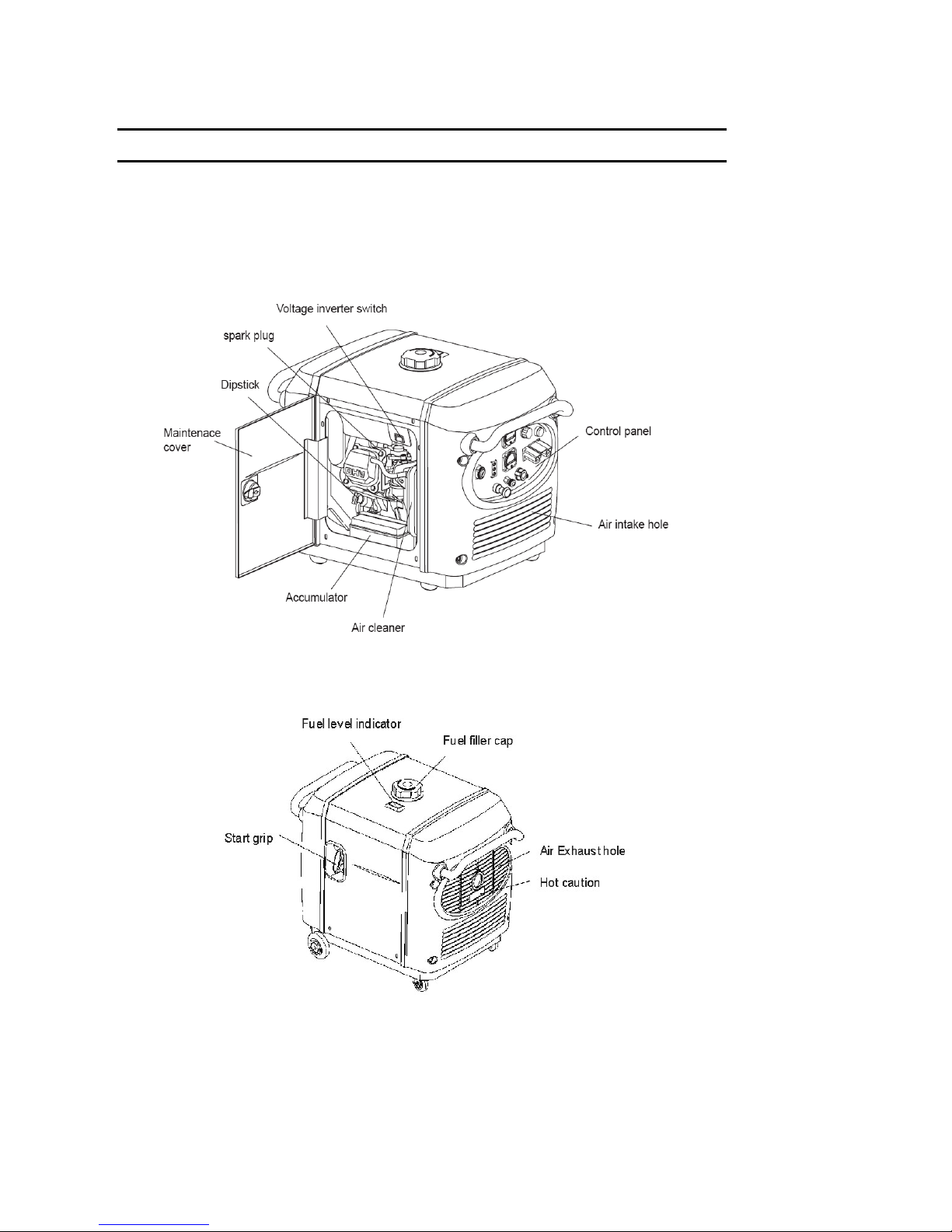
2. Parts identification
2.1 Outside overview
See Fig.1.
Fig.1 Outside view
4
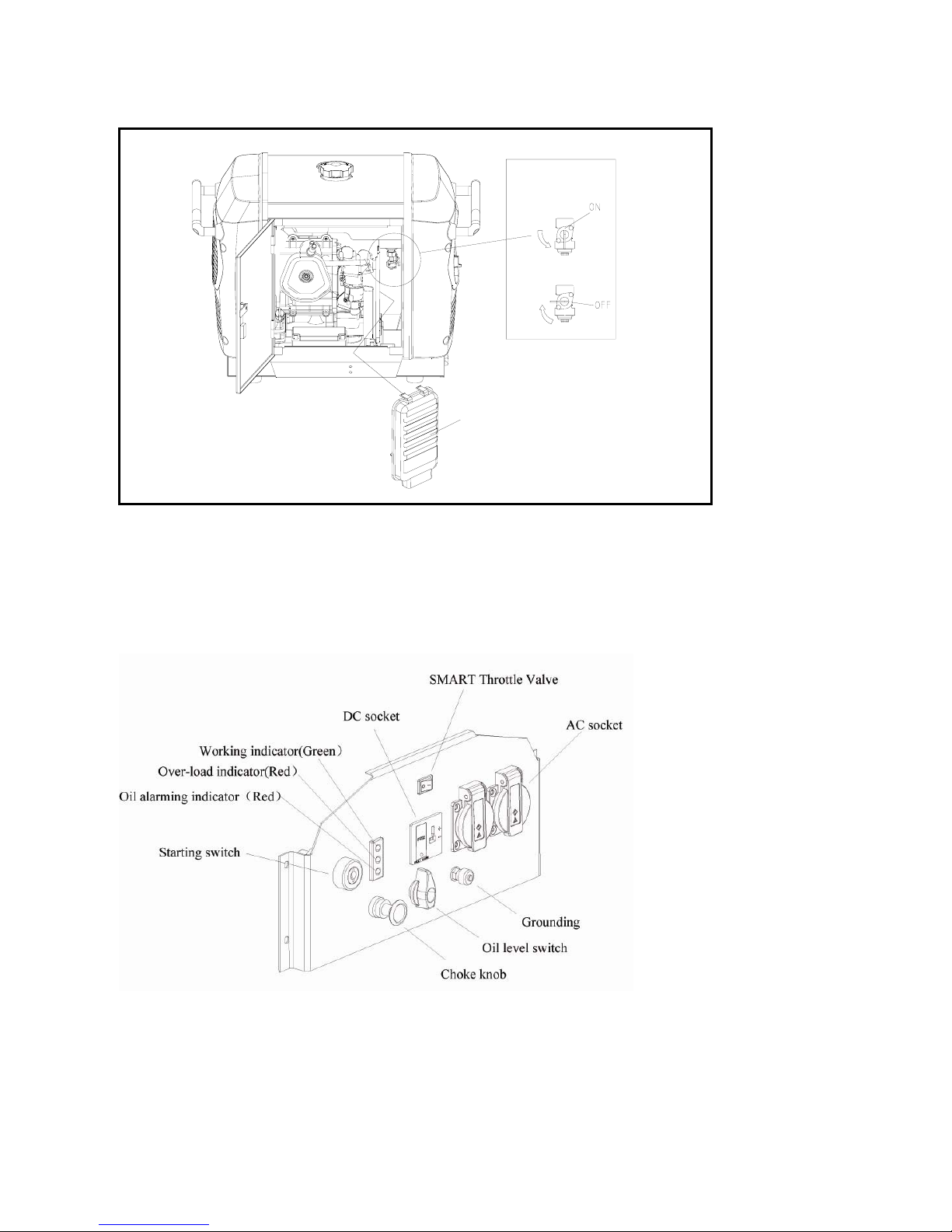
Oil level switch
2.2 Control panel
2.2.1 IG3000 Control panel
See Fig. 2
Fig.2 IG3000 Control panel
油开关
空滤盖
IG4000 oil level
switch
A
ir filter cove
r
5
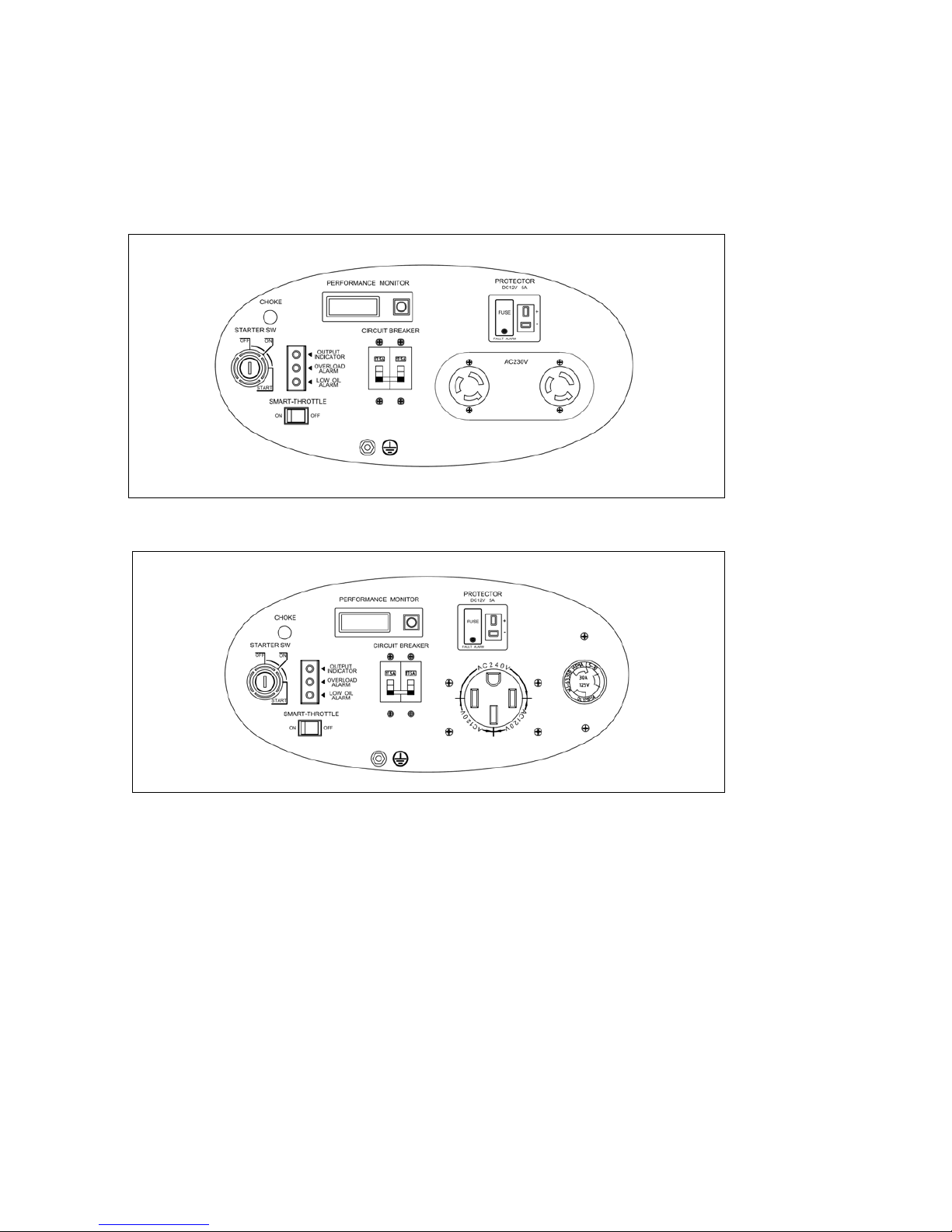
2.2.2 IG4000 Control panel
See Fig.3 and Fig.4
(1) IG4000 single-voltage control panel
Fig.3 IG4000 single-voltage control panel
(2)IG4000 dual-voltage control panel
Fig. 4 IG4000 dual-voltage control panel
6
2.3 SMART Energy-saving switch
ON:
Generator would be at idle state if electrical appliance is disconnected from engine;
Engine would return to normal speed once connected with appliance. This equipment
is to reduce oil consumption in running.
CAUTION
■ (SMART) energy saving switch cannot run effectively when greater instant
power is needed.
■ Shut down energy saving switch to reduce voltage variation when generator is
connected with high electrical load.
■ Close energy saving switch during DC operation.
OFF:
Indicates that smart energy saving switch is closed and engine is at high rotation
speed.
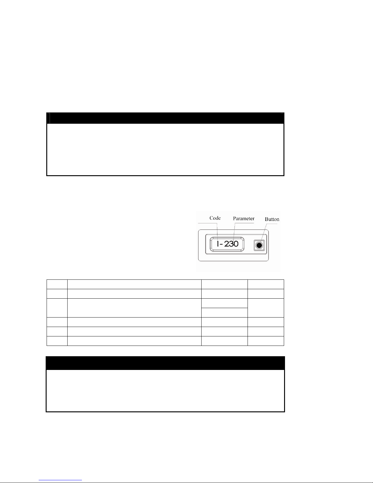
2.4 LCD parameters display
2.4.1 Single-voltage LCD-230V
LCD will display the following parameters in cycle
after powered on:
No. Parameters Unit Note
1 Genset voltage 1 V V
1 A
2 Genset current
0.1 A
A
3 Genset frequency 0.1 Hz Hz
4 Battery voltage 0.1 V V
5 Accumulated running time 0.1 Hour Hr
CAUTION
■ LCD back light lights for 10 seconds then goes out automatically once pushed
button.
■ When the current displayed parameter is not “genset voltage”, displayed
parameter will switch to “genset voltage” automatically after 30 seconds.
7
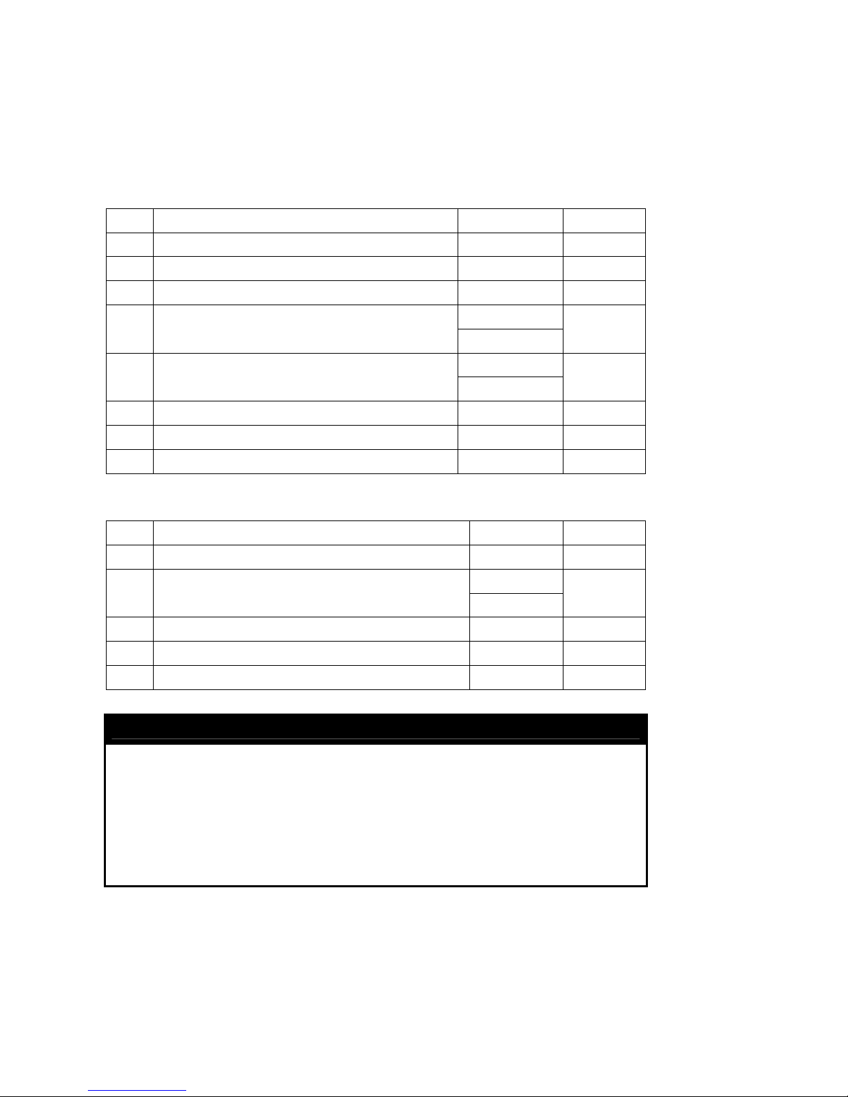
2.4.2 Dual-voltage LCD-120/240V
After the system is powered on, self-check indicator lights and buttons are pushed
continually, the following parameters will be displayed in cycle:
(1) Displayed parameters in series connection:(120/240V simultaneous output)
No. Parameters Unit Note
1 Genset AB-Phase voltage 1 V V
2 Genset A-Phase voltage 1V V
3 Genset B-Phase voltage 1V V
1 A
4 Genset A-Phase current
0.1 A
A
1 A
5 Genset B-Phase current
0.1 A
A
6 Genset frequency 0.1 Hz Hz
7 Battery voltage 0.1 V V
8 Accumulated running time 0.1 Hour Hr
(2) Displayed parameters in parallel connection:(120V output)
No. Parameters Unit Note
1 Genset voltage 1 V V
1 A
4 Genset current
0.1 A
A
6 Genset frequency 0.1 Hz Hz
7 Battery voltage 0.1 V V
8 Accumulated running time 0.1 Hour Hr
CAUTION
■ LCD back light lights for 10 seconds then goes out automatically once pushed
button.
■ When the current displayed parameter is not “genset voltage”, displayed
parameter will switch to No.1 listed parameters after 30 seconds.
■ Parameter will be displayed as“――――――” when voltage selection switch is at
incorrect position.
 Loading...