

Kipor Sinemaster IG200, Sinemaster IG2000p, Sinemaster IG2000s Operation Manual

SINEMASTER
DIGITAL INVERTER GENERATOR
IG2000
IG2000s
IG2000p
WUXI KIPOR POWER CO., LTD.
R
R


PREFACE
Thank you for purchasing our generators.
This manual covers operation and maintenance of the IG2000, IG2000s, IG2000p
generator.
All information in this publication is based on the latest product information
available at the time of approval for printing.
We reserve the right to make changes at any time without notice and without
incurring any obligation.
No part of this publication may be reproduced without written permission.
This manual should be considered a permanent part of the generator and should
remain with it if it is resold.
Pay special attention to statements preceded by the following words;
Failure to properly follow these precautions can result in
property damage, serious injury or DEATH!
Read all labels and the owner's manual before operating
this generator.
Operate only in well ventilated areas. Exhaust gas
contains poisonous carbon monoxide, and can be deadly.
Always stop engine before refueling. Wait 5 minutes
before restarting.
Check for spilled fuel or leaks. Clean and/or repair before
use.
Keep any sources of ignition away from fuel tank, at all
times.
Indicates a strong possibility of severe personal injury or
death if instructions are not followed.
Indicates a possibility of personal injury or equipment
damage if instructions are not followed.
NOTE: Gives helpful information.
If a problem should arise, or if you have any questions about the generator,
consult an authorized dealer.
The generators are designed to give safe and dependable
service if operated according to instructions. Read and
understand the Owner's Manual before operating the generator. Failure to do so could result in personal injury or
equipment damage.
The illustration may vary according to the type.
WARNING
CAUTION
WARNING
WARNING
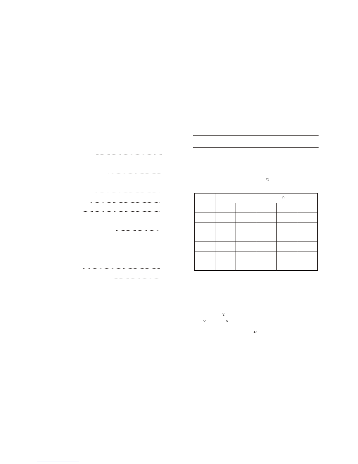
The conditions of generator rated output:
Altitude: 0 m Ambient temperature: 25 Relative humidity: 30%
Ambient modified coefficient: C (Relative humidity 30%)
Note: When the relative humidity is 60%, the modified coefficient is C-0.01
When the relative humidity is 80%, the modified coefficient is C-0.02
When the relative humidity is 90%, the modified coefficient is C-0.03
When the relative humidity is 100%, the modified coefficient is C-0.04
Counting example:
When the rated power of generator is P =5KW, altitude is 1000m, ambient
N
temperature is 35 , relative humidity is 80%, the rated power of generator is:
P=P (C-0.02) = 5 (0.82-0.02) = 4KW
N
Modified coefficient table
of ambient condition power
Ambient temperature ( )
Altitude
(m)
0
500
1000
2000
3000
4000
25
1
0.93
0.87
0.75
0.64
0.54
30
0.98
0.91
0.85
0.73
0.62
0.52
35
0.96
0.89
0.82
0.71
0.6
0.5
40
0.93
0.87
0.80
0.69
0.58
0.48
45
0.90
0.84
0.78
0.66
0.56
0.46
15. APPENDIX
--
1. SAFETY INSTRUCTIONS
2. SAFETY LABEL LOCATIONS
3. COMPONENT IDENTIFICATION
4. PRE-OPERATION CHECK
5. STARTING THE ENGINE
High altitude operation
6. GENERATOR USE
7. STOPPING THE ENGINE
8. DOUBLE GENERATORS PARALLEL
9. MAINTENANCE
10. TRANSPORTING/STORAGE
11. TROUBLESHOOTING
12. SPECIFICATIONS
13. ELECTRICAL WIRING DIAGRAM
14. LIGHT KIT
15. APPENDIX
CONTENTS
1
3
5
9
13
16
17
24
26
30
37
39
41
42
44
45
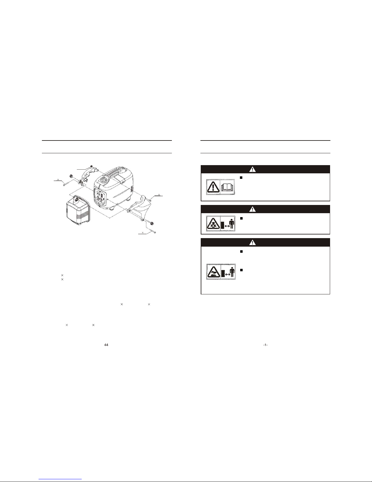
14. LIGHT KIT
Our IG2000s Light kit is designed specifically for use on IG2000 Generator.
Tools required: Phillips Screwdriver
Fittings supplied:
(1) IG2000 Portable Digital Generator
(2) KGE2000Tsi-05100 Light Kit Assembly
(3) KGE1000Tsi-05001a Nut
(4) KGE1000Tsi-05002a Threaded screw
(5) KGE2000Tsi-05003 Left Mount Plate of Light Housing
(6) KGE2000Tsi-05004 Right Mount Plate of Light Housing
(7) Screw M5 65 2PCS
(8) Screw M5 16 1PCS
(9) Nut M5 1PC
This is where the Light Kit will be mounted, see IG2000s Assembly Drawing of the Portable
Digital Generator Light Kit.
(1) Remove the screw from the IG2000 Portable Digital Generator and the screws from the
side of the control plate;
(2) Disperse the mount plate of the Light, use screw M5 65 and screw M5 16, then locate
the mount plate of Light Housing on generator. DO NOT TIGHTEN SCREWS.
(3) Use the threaded screw through the Light, left and right mount plate in turn, then lock the
nut.
(4) After adjusting the turnover angular of Light, tighten the avove mentioned of threaded
screw, screw M5 65 and screw M5 16 in turn.
Before energizing the light, be sure to read the Generator Owner's Manual for best operation
and maintenance information, along with the safety precautions. It is recommended that the
light switch be in the OFF position when starting the generator.
MOUNTING INSTRUCTIONS FOR: IG2000s LIGHT KIT
M5 65
M5 65
M5 16
--
1. SAFETY INSTRUCTIONS
To ensure safe operation
WARNING
The generators are designed to give safe and depend-
Read and understand the Owner's Manual before op erating the generator. Failure to do so could result in
WARNING
WARNING
able service if operated according to instructions.
personal injury or equipment damage.
Exhaust gas contains poisonous carbon monoxide.
Never run the generator in an enclosed area.
Be sure to provide adequate ventilation.
The muffler becomes very hot during operation and
remains hot for a while after stopping the engine.
Be careful not to touch the muffler while it is hot.
Let the engine cool before storing the generator indoors.
The engine exhaust system will be heated during
operation and remain hot immediately after stopping
the engine.
To prevent scalding, pay attention to the warning marks
attached to the generator.
M5 Nut
IG2000p
--
WARNING
SAFETY INSTRUCTIONS
To ensure safe operation
Gasoline is extremely flammable and explosive under certain conditions.
Refuel in a well ventilated area with the engine stopped.
Keep away from cigarette, smoke and sparks when refueling the
generator, Always refuel in a well-ventilated location.
Wipe up spilled gasoline at once.
WARNING
Always make a pre-operation inspection (page 9) before you start the
engine. You may prevent an accident or equipment damage.
Place the generator at least 1m(3ft) away from buildings or other
equipment during operation.
Operate the generator on a level surface. if the generator is tiled, fuel
spillage may result.
Know how to stop the generator quickly and understand operation of all
the controls. Never permit anyone to operate the generator without proper
instructions.
Keep children and pets away from the generator when it is in operation.
Keep away from rotating parts while the generator is running.
The generator is a potential source of electrical shocks when misused; do
not operate with wet hands.
Do not operate the generator in rain or snow and do not let it get wet.
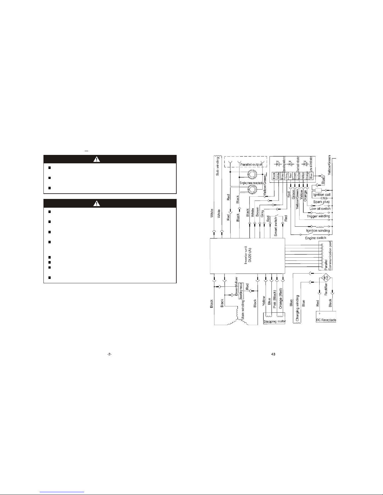
13. ELECTRICAL WIRING DIAGRAM
--
IG2000 / IG2000s
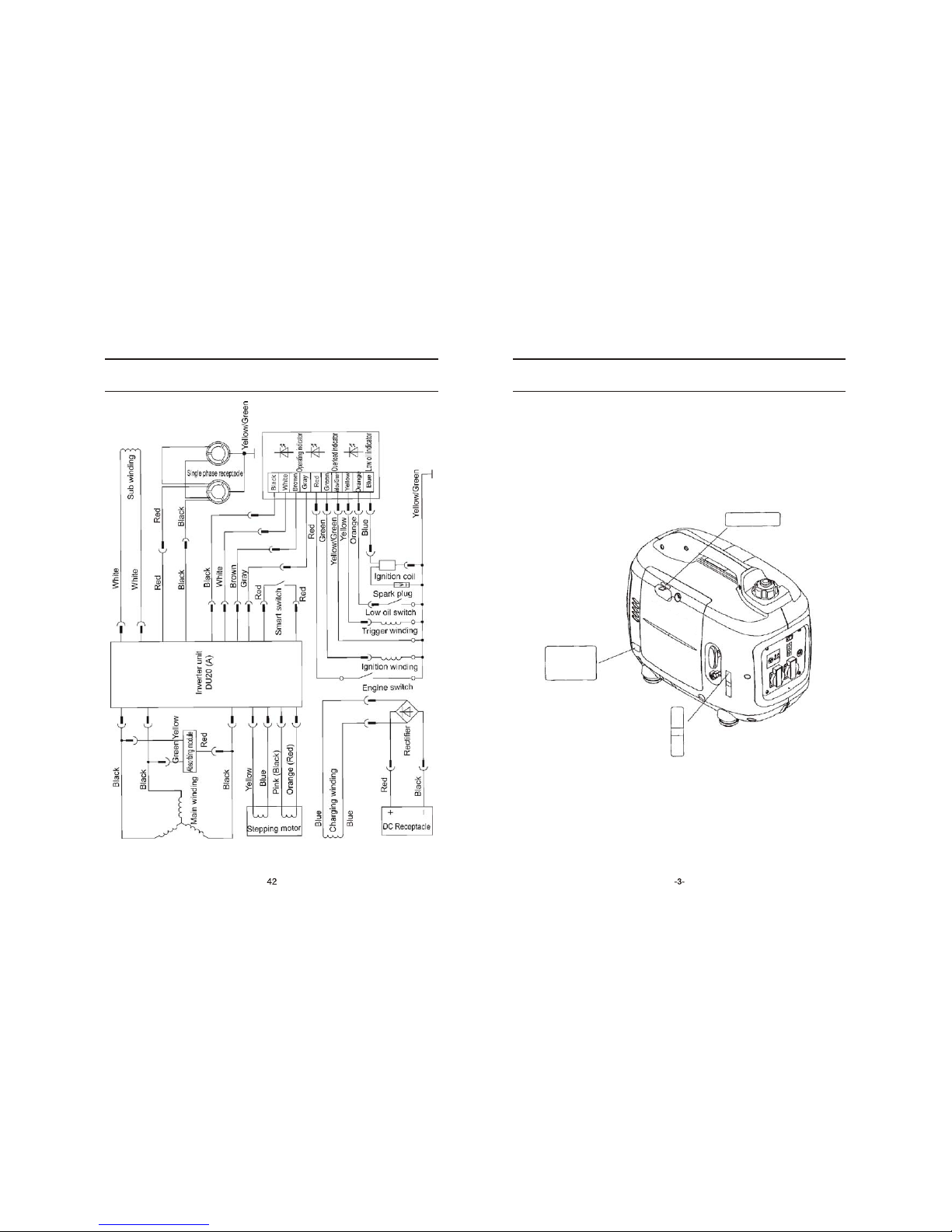
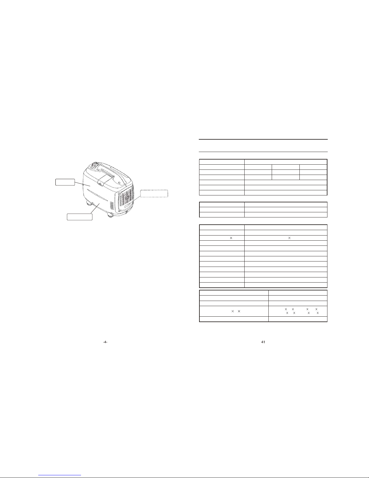
2. SAFETY LABEL LOCATIONS
These lables warn you potential hazards that can cause serious injury. Read the
labels and safety notes and precautions described in manual carefully.
If a label comes off or becomes hard to read, contact your dealer for a
replacement.
CHOKE HANDLE
LOW OIL ALARM
ENGINE SWITCH
--
SAFETY CAUTION
MODEL
HOT CAUTION
12. SPECIFICATIONS
DC output
DC voltage
Electric circuit breaker
Phase number
12V-8.3A
Available
Single phase
SPECIFICATIONS
Model
IG2000/IG2000s/IG2000p
Rated frequency (Hz)
Rated voltage (V)
Rated current (A)
Rated speed (rpm)
Rated output (kVA)
Max. output (kVA)
50
230
7.0
4500
1.6
2.0
60
240
6.7
Engine
Model Type
KG158
Type
Displacement (Bore Stroke)
Compression ratio
Rated power[kVA(Hp)/(r/min)]
Rated rotation speed (rpm)
Ignition system
Spark plug
Starting system
Fuel
.
Fuel consumption (g /kW h)
Lube oil
Single cylinder, 4 stroke, vertical, air-cooled, OHV, gasoline engine
105.6ml (58 40mm)
8.5:1
2.2/4500
4500
T. C. I
BOSCH R6 SUF
Recoil starter
Automotive unleaded gasoline
420
CD grade or SAE 10W-30,15W-40
Fuel tank capacity (L)
Continuous running time (hr) (at rated output)
Noise level(zero load~ full load) [dB(A)/7m]
3.7
3.0
61-73 *
Dry weight [kg(lbs)]
IG2000: 22 (48.4) IG2000s: 23.5 (51.7)
IG2000: 549 291 405(21.61 11.46 15.94)
IG2000s: 660 296 431(25.98 11.65 16.97)
60
120
13.3
Overall dimension (L W H) [mm(in)]
NOTE: IG2000 type is basic type; IG2000s type is with light kit; IG2000p type is double generators
parallel type.
*The declared values shall consider uncertainties due to production variation and measurement
procedures.
 Loading...