

Kipor SINEMASTER IG1000s Operation Manual

IG1000
IG1000s
SINEMASTER
DIGITAL INVERTER GENERATOR
WUXI KIPOR POWER CO., LTD.
R

PREFACE
Thank you for purchasing our generators.
This manual covers operation and maintenance of the IG1000, IG1000s
generator.
All information in this publication is based on the latest product information
available at the time of approval for printing.
We reserve the right to make changes at any time without notice and without
incurring any obligation.
No part of this publication may be reproduced without written permission.
This manual should be considered a permanent part of the generator and should
remain with it if it is resold.
Pay special attention to statements preceded by the following words;
Failure to properly follow these precautions can result
in property damage, serious injury or DEATH!
Read all labels and the owner's manual before
operating this generator.
Operate only in well ventilated areas. Exhaust gas
contains poisonous carbon monoxide, and can be
deadly. Always stop engine before refueling. Wait 5
minutes before restarting.
Check for spilled fuel or leaks. Clean and/or repair
before use.
Keep any sources of ignition away from fuel tank, at all
times.
Indicates a strong possibility of severe personal injury or
death if instructions are not followed.
Indicates a possibility of personal injury or equipment
damage if instructions are not followed.
NOTE: Gives helpful information.
If a problem should arise, or if you have any questions about the generator,
consult an authorized dealer.
Our generators are designed to give safe and
dependable service if operated according to
instructions. Read and understand the Owner's Manual
before operating the generator. Failure to do so could
result in personal injury or equipment damage.
The illustration may vary according to the type.
WARNING
CAUTION
WARNING
WARNING
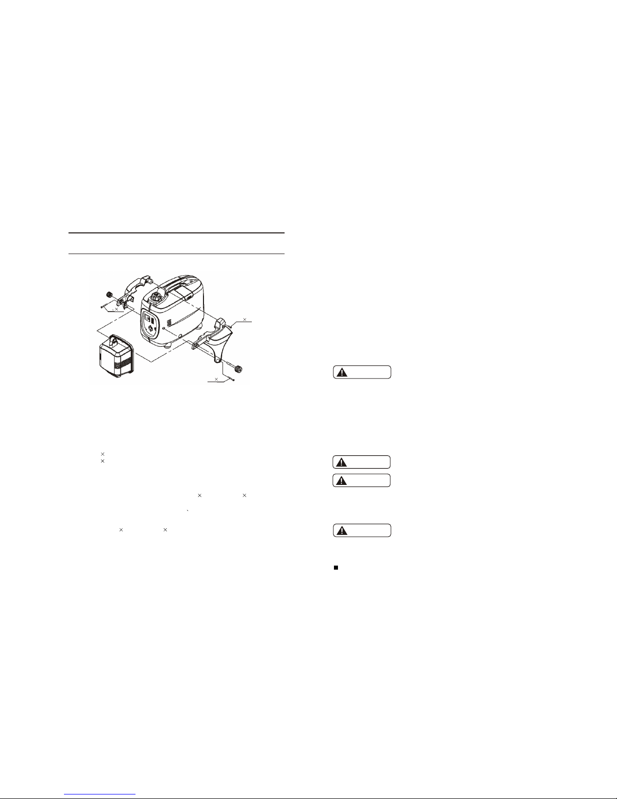
13. LIGHT KIT
Our IG1000S Light kit is designed specifically for use on IG1000 Generator.
Tools required: Phillips Screwdriver
Fittings supplied:
(1) IG1000 Portable Digital Generator
(2) IG1000s-05100 Light Kit Assembly
(3) IG1000s-05001 Antiskid Round Nut
(4) IG1000s-05001 Antiskid Round Stud
(5) IG1000s-05003 Left Mount Plate of Light Kit
(6) IG1000s-05004 Right Mount Plate of Light Kit
(7) Screw M5 45 2PCS
(8) Screw M5 16 1PCS
This is where the Light Kit will be mounted, see IG1000s assembly Drawing of the
Portable Digital Generator Light Kit.
(1) Remove the screw from the IG1000 Portable Digital Generator and the screws from the
side of the control plate;
(2) Disperse the mount plate of the Light, use screw M5 45 and screw M5 16, then locate
the mount plate of Light Kit on generator. DO NOT TIGHTEN SCREWS.
(3) Use the antiskid round stud through the Light left and right mount plate in turn, then
lock the antiskid round stud.
(4) After adjusting the turnover angular of Light, tighten the above mentioned of antiskid
round stud, screw M5 45 and screw M5 16 in turn.
Before energizing the light, be sure to read the Generator Owner's Manual for best operation
and maintenance information, along with the safety precautions. It is recommended that the
light switch be in the OFF position when starting the generator.
M5 45
M5 45
M5 16
MOUNTING INSTRUCTIONS FOR: IG1000s LIGHT KIT
36
Fuse
35
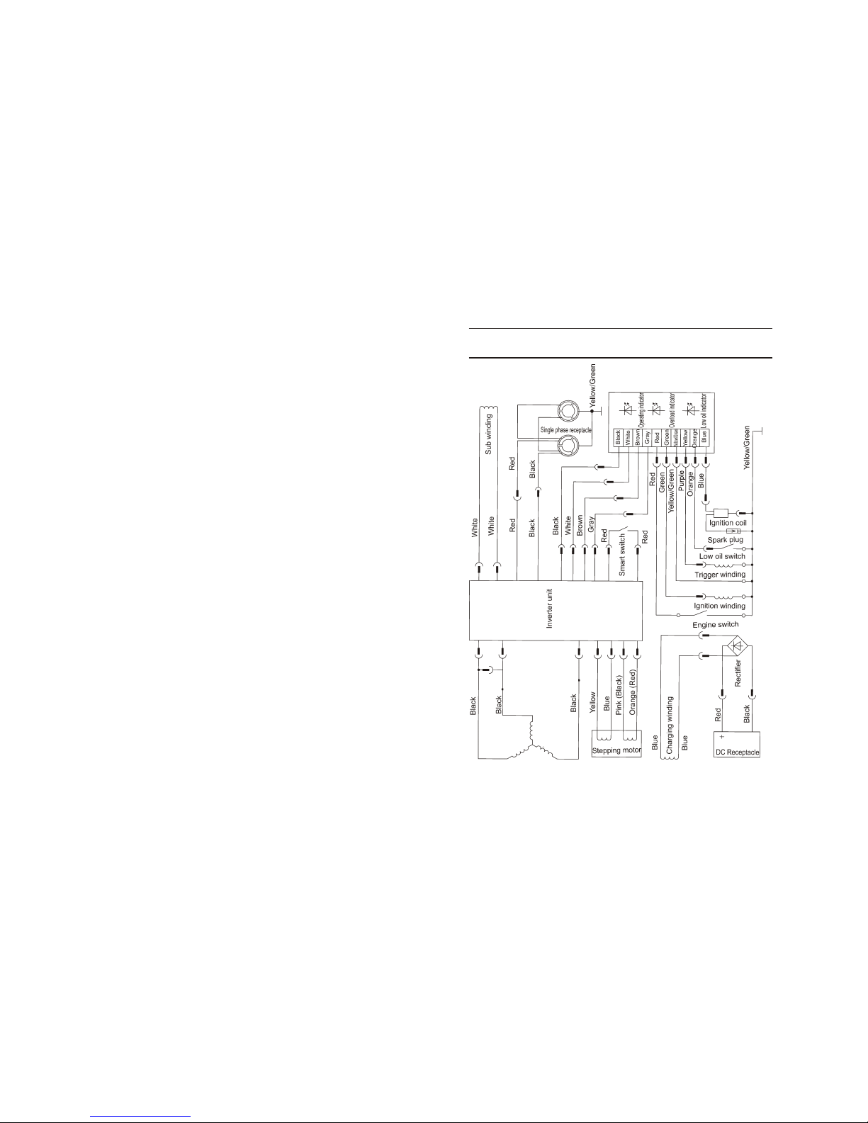
12. ElECTRIC DIAGRAM
11. SPECIFICATIONS
34
CONTENTS
1. Safety Instructions
2. Safety Label Locations
3. Component Indentificaction
4. Pre-operation Check
5. Starting the Engine
High altitude operation
6. Generator Use
7. Stopping the Engine
8. Maintenance
9. Transporting/Storage
10. Troubleshooting
11. Specifications
12. Electric diagram
13. Light Kit
1
3
4
7
10
12
13
21
23
30
32
34
35
36
DC output
DC voltage
Fuse
Phase number
12V-5A
With
Single phase
SPECIFICATIONS
Model
IG1000/IG1000s
Rated frequency (Hz)
Rated voltage (V)
Rated current (A)
Rated rotation speed [r/min]
Rated output (kVA)
Max. output (kVA)
50
230
3.9
5500
0.90
1.00
60
240
3.8
Engine
KG144
Fuel tank capacity (L)
Continuous running time (hr) (at rated output)
Noise level (zero load-full load) [dB(A)/7m]
2.6
5.0
54-59 *
Dry weight [kg(lbs)]
60
120
7.5
Overall dimension (L W H) [mm(in)]
*The declared values shall consider uncertainties due to production variation and measurement
procedures.
IG1000: 460X248X395(18.11 9.76 15.55)
IG1000s: 605X250X400(23.82 9.84 15.75)
IG1000: 14(30.8) IG1000s: 15.5(34.1)
Model Type
Type
Displacement (Bore Stroke)
Compression ratio
Rated power [kW(Hp)/(r/min)]
Rated rotation speed [rpm]
Ignition system
Spark plug
Starting system
Fuel
Fuel consumption (g/kW.h)
Lube oil
Single cylinder, 4 stroke, OHV, gasoline engine
53.5ml (43.5 36mm)
8.5:1
1.2/5500
5500
T.C.I
UR5/A7RTC
Recoil starter
Automotive unleaded gasoline
420
CD grade or SAE 10W-30 15W-40
33
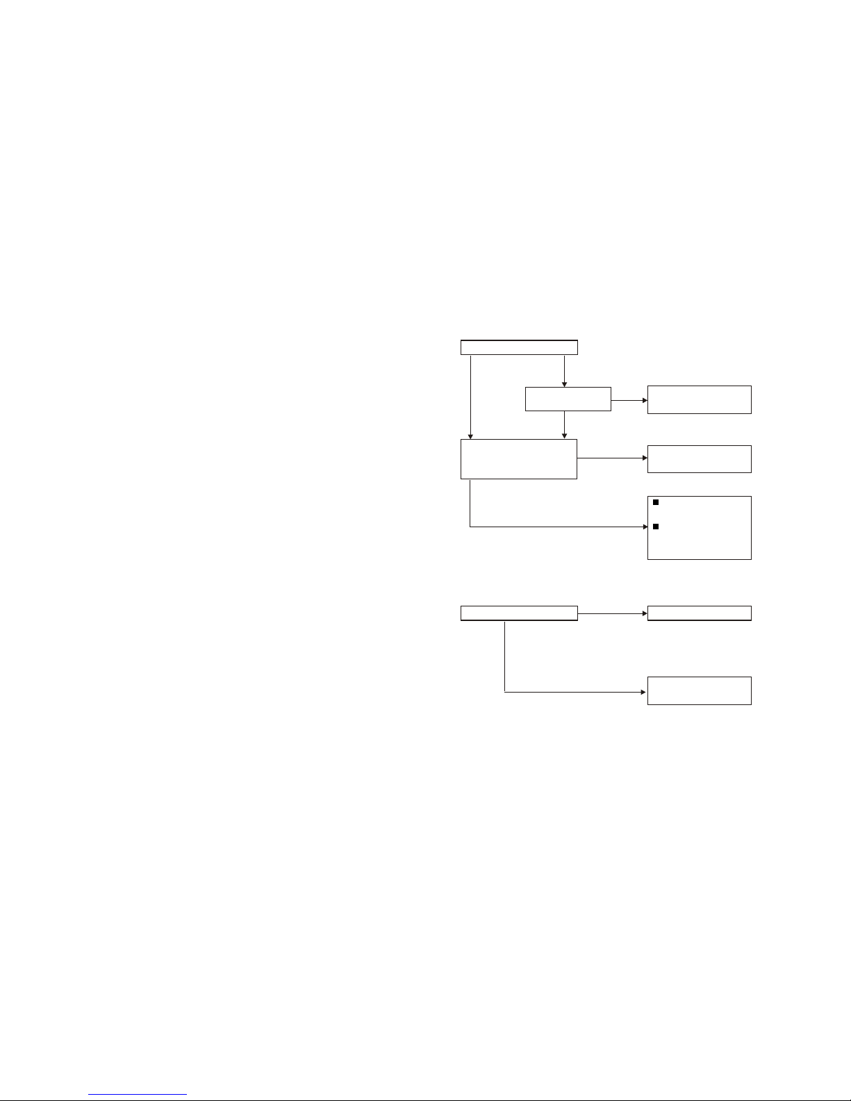
Appliance does not operate:
Is the output indicator light ON?
YES
NO
NO
YES
Check the electrical appli-
ance or equipment for any
defects.
Take the generator to an
authorized dealer.
NO
Take the generator to an
authorized dealer.
YES
Replace the electrical
appliance or equipment
Take the electrical appli-
ance or equipment to an
electrical shop for repair
Replace the fuse.
YES
No electricity at the DC receptacle:
Is the DC circuit fuse burnt out?
Take the generator to an
authorized dealer.
Is the overload
indicator light ON?
NO
1
32
10.TROUBLESHOOTING
When the engine will not start:
Refill the fuel tank.
Turn the engine switch on.
Add the recommended oil.
Is there fuel in the tank?
Is the engine switch on?
Is there enough oil in the engine?
YES
NO
YES
YES
NO
NO
NO Still no
spark
Is there a spark from
the spark plug?
Replace the
spark plug.
Take the generator to an
authorized dealer.
If the engine still does not
start, take the generator to
an authorized dealer.
Be sure there is no spilled
fuel around the spark pulg.
Spilled fuel may ignite.
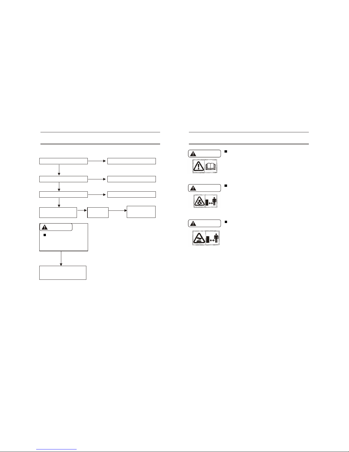
1. SAFETY INSTRUCTIONS
WARNING
WARNING
WARNING
Our generators are designed to give safe and depend-
able service if operated according to instructions.
Read and understand the Owner's Manual before operating the generator. Failure to do so could result in
personal injury or equipment damage.
Exhaust gas contains poisonous carbon monoxide.
Never run the generator in an enclosed area.
Be sure to provide adequate ventilation.
When installed in ventilated protection are to be
observed.
The muffler becomes very hot during operation and
remains hot for a while after stopping the engine.
Be careful not to touch the muffler while it is ho t.
Let the engine cool before storing the generator
indoors.
The engine exhaust system will be heated during operation and remain hot immediately after stopping the
engine.
To prevent scalding, pay attention to the warning
marks attached to the generator.
WARNING
To check:
1)Remove the spark plug cap and clean
any dirt from around the spark plug.
2)Remove the spark plug and install the
spark plug in the plug cap.
3)Set the plug side electrode on the cylin-
der head to ground.
4)Pull the recoil starter, sparks should
jump across the gap.
 Loading...