

Kipor KM2V80 User Manual

Thank you for purchasing Kipor KM2V80 series diesel engine. In order to ensure proper
operation, reliable running and good economic benefit of your machine, it is especially important
for you to operate correctly and maintain carefully. This manual will tell you how to operate and
maintain the machine correctly, it will also give you detail instruction about the main technical
specification, configuration and troubleshooting.
Content
Instruction of products……………………………………………………………………………..1
1. Brief instruction of products……………………………………………………………....1
2. Composition of model and its meaning………………….………………………………1
3. External installation drawings and names of parts……………………………………. 2
4. Specification………………………………………………………………………………. 6
5. Main adjusting parameter………………………………………………………………… 7
6. Tighten torque values of main bolts and nuts……………………………………………7
7. Fit clearance and interference table………………………………………………………8
Technical maintenance………………………………………………………………………………9
1. Daily check and periodic check …………………………………………………….9
2. Procedure of periodic maintenance………………………………………………………..9
Disassembly and reassembly…………………………………………………………………….. 13
1. Basic procedure of disassembly…………………………………………………………..13
2. Basic procedure of reassembly……………………………………………………………18
Check and maintenance……………………………………………………………………………22
1. Cylinder cover…………………………………………………………………………….. 22
2. Camshaft...............................………………………………………………………………23
3. Piston and piston pin……………………………………………………………………… 24
4. Crankshaft………………………………………………………………………………… 25
5. Cylinder block and cylinder cover................................................................................
6. Lubrication system……………………………………………………………………….. 27
7. Cooling system…………………………………………………………………………… 27
8. Fuel system……………………………………………………………………………… 28
The electrical system…………………………………………………………………………… 29
1. Starter motor……………………………………………………………………………… 29
2. Heater plug............…………………………………………………………………… .31
Troubleshooting and remedy of engine………………………………………………………...35
Preliminary run...........................................................................................................….........39

Instruction of products
1. Brief instruction of products
This model is double cylinder, V-type, four strokes, water cooled, and swirl type diesel engines.
This model will be exploited into multi-purpose engine with vertical or horizontal shaft.
This model is simple in structure, convenient in disassembly or reassembly, and have smart
size, short axial length, light weight, good performance, reliable quality, long running time. They
will meet various demands for each customer, and are ideal complementary power for
generating sets, construction machinery, ship, combined harvester, agricultural machine etc.
Welcome you to purchase.
2. Composition of model and its meaning
KM 2 V 80
Cylinder bore (mm)
V-type
Cylinder No.
Kipor
Introduction of products

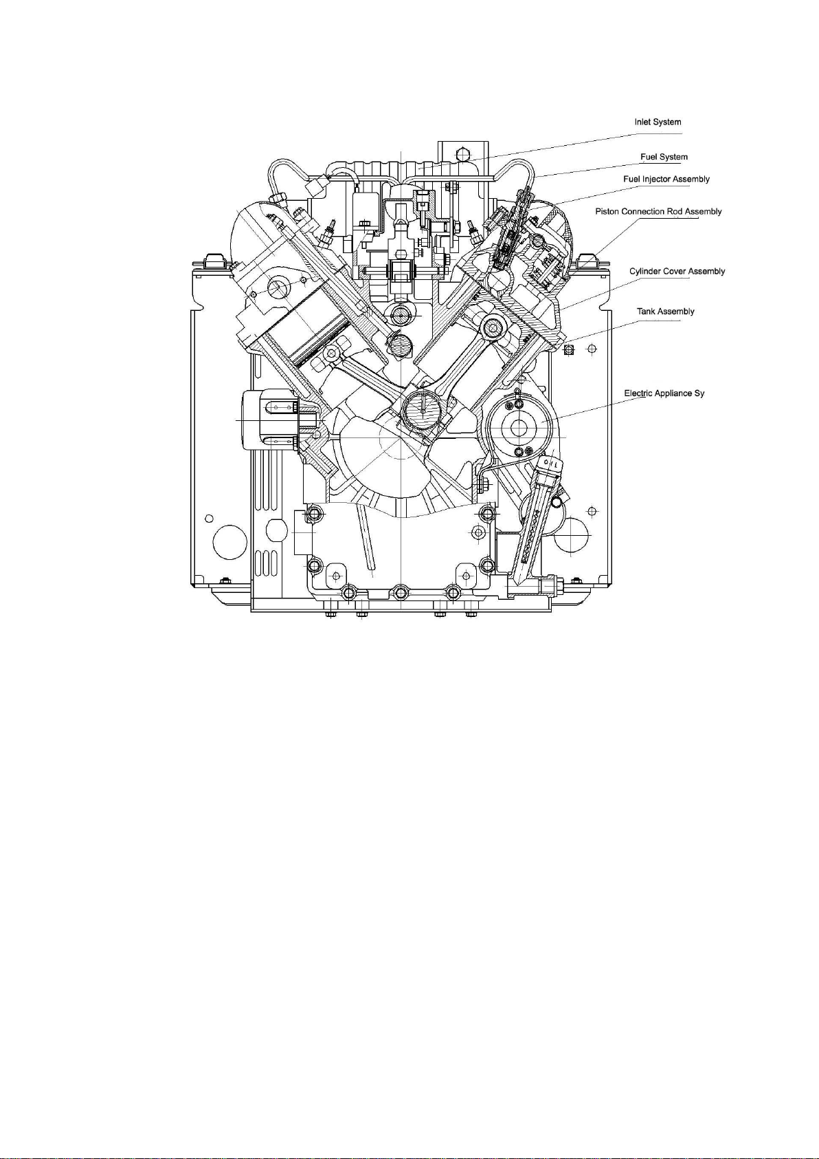
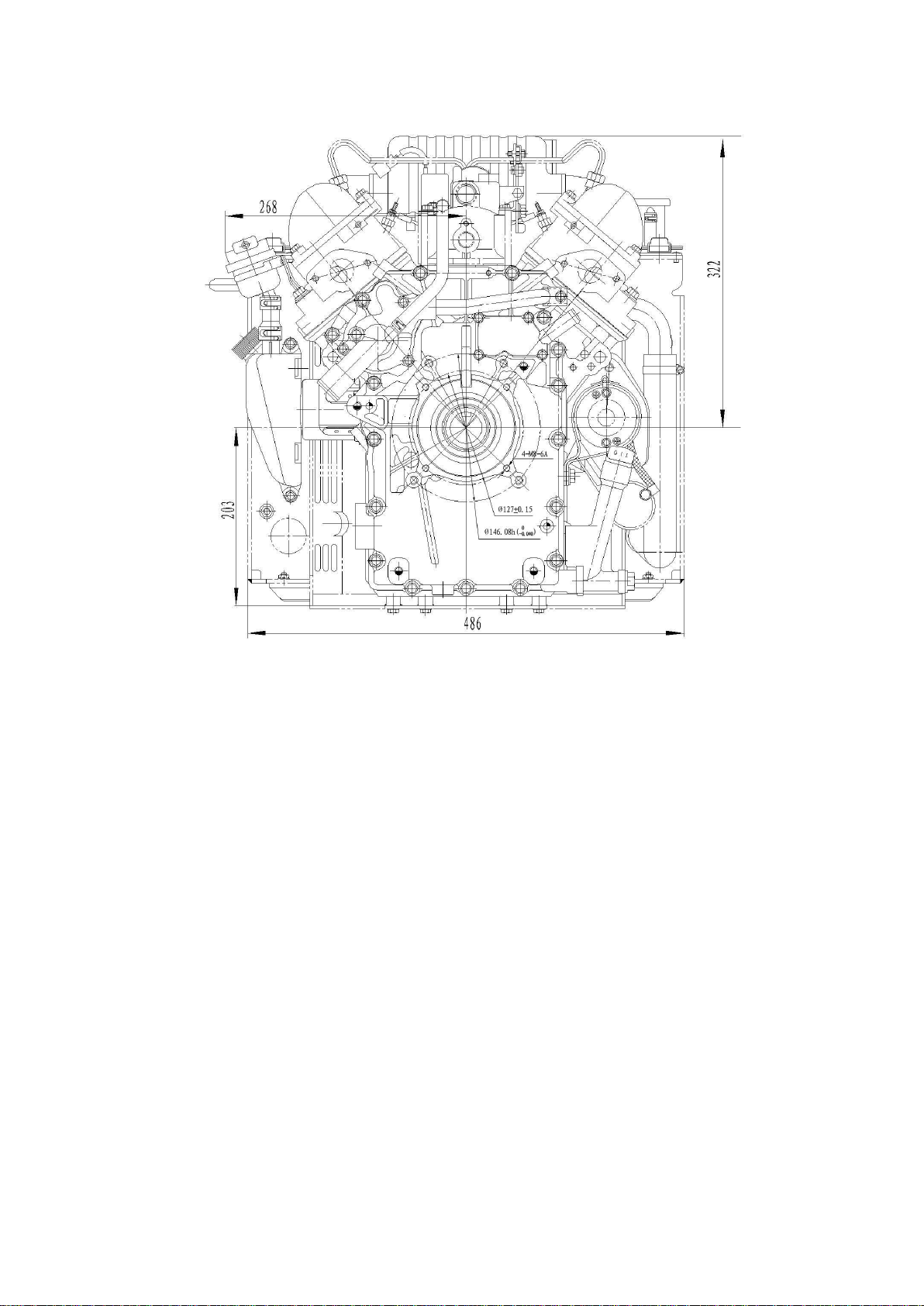
3. External installation drawings and name of parts
Please refer to picture 1, picture 2, picture 3 and picture 4 for details.
Picture1 Vertical section view for KM2V80 diesel engine
Picture 2 Horizontal section view for KM2V80 diesel engine
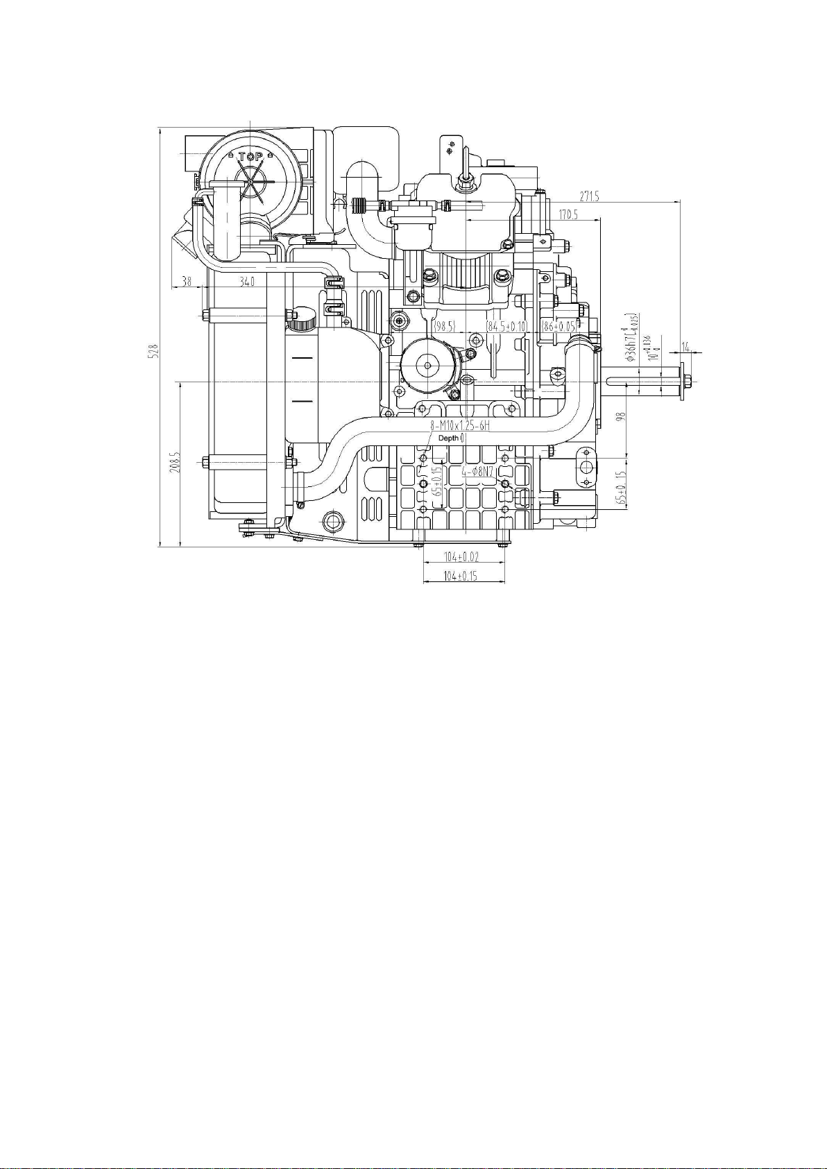
Picture 3 Vertical figuration view for KM2V80 diesel engine
Picture 4 Horizontal figuration view for KM2V80 diesel engine

4. Specification
Table 1 Main specification table of KM2V80 diesel engine
Model
KM2V80
Type
Double cylinder, V-type, water-cooled, 4 stroke,
swirl type
Bore×Stroke mm
80×79
Displacement L
0.794
Compression ratio
23
Rated output/Rated speed
kW/r/min
12.5/3000
14.5/3600
Max. torque N·m
49/1600~1800
Min. speed (zero load) r/min
≤900
Lubricating system
Pressure splashed
Starting system
Electric starter
Output terminal direction (face
to the flywheel)
Anticlockwise
Fuel type
0#(summer), -10# or -20#(winter), -35#(chillness)
Fuel consumption ratio g/(kW·h)
285
297
Lube oil type
SAE 10W-30、20W-40 or L-ECD Grade
Lube oil capacity L
2.27
oil consumption ratio g/(kW·h)
≤5
Starting motor capacity V,kW
12V 1.4 kW
Charging generator capacity
(V,A)
12V 20A
Battery capacity (V,AH)
12V 60AH
Overall dimension (L×W×H) mm
616×486×528
Net weight kg
58
5. Main adjusting specification
Table 2 Main adjusting specification of KM2V80 diesel engine
Item
Standard value
Cylinder compression clearance height
mm
0.88~1.2
Advanced angle of fuel supply
BTDC 18.5°±1°
Fuel spraying pressure Mpa
13°±0.5°
Valve timing
Inlet valve
Open at BTDC 22°
Close at ABDC 56°
Exhaust valve
Open at BTDC 61°
Close at ATDC 26°
Valve clearance mm (cooled state)
0.10~0.15
Valve sunk volume mm
0.5±0.10
Oil pressure Mpa
0.25~0.5
6. Tighten torque of main bolt and nut
Table 3 Tighten torque of main bolts and nuts
Value
Item
Thread
Tighten torque
(N·m )
Remark
Cylinder cover bolt
M9×1.25
60±5
Connection rod bolt
M7×1
28±2
Flywheel bolt
M10×1.25
75~80
Crankcase cover bolt
M8×1.25
22~25
Fuel injector bolt
M20×1.5
50±5
Heater plug
M10×1.25
12±2
General bolt: mechanical performance
is 8.8 grade
M6×1.0
8~12
M8×1.25
17~23
M10×1.5
40~50
M12×1.75
85~100
M14×1.5
130~150
M16×1.5
220~240

7. Fit clearance and interference table
Table 4 Fit clearance and interference table
No.
Name
Standard dimension(mm)
Fitting clearance
(mm)
Remark
1
Cylinder inner diameter/
Piston top outer diameter
φ80H7(
+0.03
0
)/d-0.515±0.01
0.565~0.635
2
Cylinder inner diameter/
Piston skirt upper part
φ80H7(
+0.03
0
)/d-0.125±0.01
0.175~0.245
3
Cylinder inner diameter/
Piston skirt diameter
φ80H7(
+0.03
0
)/φ80
-0.06
-0.08
0.06~0.110
4.
Piston pin hole/Piston pin
φ20
-0.002
-0.008
/φ20
0 -
0.006
0.004~-0.008
5
The width of ring groove /
The height of 1
st
ring
1.2
+0.060
+0.040
/1.2
-0.01
-0.02
0.05~0.08
6
The width of ring groove /
The height of 2
nd
ring
1.5
+0.040
+0.020
/1.5
-0.01
-0.02
0.03~0.06
7 The width of ring groove /
The height of 3
rd
ring
3.0
+0.030
+0.010
/3
-0.01
-0.02
0.02~0.05
8
Open clearance of 1
st
ring
0.25~0.35
9
Open clearance of 2
nd
ring
0.20~0.35
10
Open clearance of 3
rd
ring
0.15~0.30
11
Connection rod bushing/
Piston pin diameter
φ20
+0.025
+0.015
/φ20
0 -
0.006
0.015~0.031
12
Connection rod bush hole diameter/
Connection rod journal
φ40
+0.032
0
/φ40f5(
-0.025
-0.036
)
0.025~0.062
13
Main bearing bushing hole diameter/
Main journal
φ50
+0.035
+0.015
/φ50f5(
-0.025
-0.036
)
0.040~0.071
14
Crankshaft axial clearance
120.7
+0.10
0
/108.6+12=120.6
0 -
0.10
0.10~0.30
15
Crankshaft axial open split/
The width of connection rod big head
40
+0.25
+0.10
/20
-0.15
-0.20
×2=40
-0.30
-0.40
0.40~0.65
16
(Crankshaft center line to the tank
top)/(piston + connection rod + crank
radius)
13.01.1935.395.1251.28
03.054.193
0.28~0.60
17
Camshaft hole diameter/
Camshaft journal
φ18H7(
+0.018
0
)/φ18e6(
-0.032
-0.043
)
0.032~0.061
18
Side cover camshaft hoe diameter/
Camshaft journal
φ24H7(
+0.021
0
)/φ24f6(
-0.040
-0.053
)
0.040~0.074
19
Camshaft axial clearance
176.5
+0.10
0
/164.1+12.2=176.3±0.05
0.035~0.15
20
Valve tappet hole/
Tappet diameter
φ10H7(
+0.015
0
)/φ10e7(
-0.025
-0.040
)
0.025~0.055
21
Fuel pump tappet hole/
Fuel pump tappet
φ21H7(+0.021 )(
0
)/φ21
-0.047
-0.080
0.047~0.101
22
Valve pipe/ Inlet valve
φ6H7(
+0.012
0
)/φ6
-0.030
-0.045
0.03~0.057

23
Valve pipe/ Exhaust valve
φ6H7(
+0.012
0
)/φ6
-0.035
-0.050
0.035~0.062
24
Cylinder cover pipe hole/
Valve pipe
φ10H7(
+0.015
0
)/φ10
+0.055
+0.045
-0.03~-0.055
25
Cylinder cover housing washer hole/
Inlet valve housing washer
φ33.5H7(
+0.025
0
)/φ33.5
+0.12
+0.09
-0.065~-0.012
26
Cylinder cover housing washer hole/
Exhaust valve housing washer
φ28H7(
+0.021
0
)/φ28
+0.11
+0.09
-0.069~-0.11
27
Cylinder cover insert/
Combustion chamber insert
φ32.5H7(
+0.021
0
)/32.5p6(
+0.042
+0.026
)
-0.005~-0.042
28
Cylinder cover rocker shaft hole/
Rocker shaft diameter
φ12H7(
+0.018
0
)/φ12f6(
-0.016
-0.027
)
0.016~0.045
29
Rocker arm hole/
Rocker shaft diameter
φ12H7(
+0.018
0
)/φ12f6(
-0.016
-0.027
)
0.016~0.045
30
Timing gear hole/
Camshaft journal
φ24H7(
+0.021
0
)/φ25s6(
+0.048
+0.035
)
-0.014~-0.048
31
Crankshaft gear hole/
Crankshaft journal
φ50H6(
+0.016
0
)/φ50p5(
+0.037
+0.026
)
-0.010~-0.037
32
Flywheel gear ring hole/
Flywheel stop ring
φ214H7(
+0.046
0
)/φ214u7(
+0.364
+0.258
)
-0.212~-0.304
33
Connection rod small head hole/
Connection rod bushing outer
diameter
φ22H7(
+0.013
0
)/φ22r6(
+0.041
+0.028
)
-0.015~-0.041
34
Connection rod bolt hole/
Bolt location diameter
φ7.5H7(
+0.015
0
)/φ7.5f6(
-0.013
-0.022
)
0.013~0.037
35
Side cover outer rotor diameter/
Outer rotor diameter
φ41H7(
+0.025
0
)/φ41
-0.075
-0.115
0.075~0.14
36
Side cover oil pump shaft diameter/
Shaft diameter
φ11H7(
+0.018
0
)/φ11f6(
-0.016
-0.027
)
0.016~0.045
37
Inner/outer rotor hole depth/
Inner/outer rotor axial depth
12
+0.08
+0.04
/12
0 -
0.020
0.04~0.10

Technical maintenance
1. Daily check and periodic check
Engine’ performance will be deteriorated if the operation condition becomes worse or time
prolongs, such as: fuel and oil consumption increase, exhaust harmful substance increases, or
vibratory and noise increase. Please strengthen the maintenance service of engine, insist on
daily check and periodic maintenance, which will prove efficiency and prevent fault.
Check can be divided into daily check and periodic check.
Daily check: Do daily check before starting engine, and operate it as a rule.
Periodic check: Suggest you make a running diary, writing down results of everyday operation
and check, accumulating total running time. Start your periodic check and maintenance
according to below table (table 5).
Periodic check can be divided into: 50h、250h、500h、1000h、2000h(h: hours)
Time interval of periodic check can be properly advanced or delayed according to the engine’s
purpose, location condition, fuel or lube oil’s quality and other using conditions.
Table 5 Periodic check table of engine
System
Checking item
Everyday
50h
250h
500h
1000h
2000h
Fuel
Check and refill fuel oil
○ Check for oil leakage
○ Drain out fuel oil
○ Replace the oil filter element
◎
Lube oil
Check and refill lube oil
○
Check for oil leakage
○ Replace lube oil
◎first
time
◎seco
nd time
Replace lube filter element
Cooling
water
Check and refill cooling water
○ Clean radiator element
○ Replace cooling water
◎
Wash and maintain cooling
system
●
Robber
pipe
Replace fuel pipe and cooling
water tube
○
◎
Operation
system
Speed regulator operation
○ Idle adjust
●
Inlet
system
Clean and replace air cleaner
element
○clean
◎
Electric
parts
Check alarm
○
Check electrolyte and charge
the battery
○
Cylinder
cover
Adjust clearance of
intake/exhaust valve
○first
time
○seco
nd
time
Wear of intake/exhaust valve
sealing ring belt
●
○:check ◎:replace ●:Contact with Kipor
agent
2. Procedure of periodic check
2.1 First 50h operation check
At the beginning time of operation, the inner parts wear
mutually and the lube oil is polluted soon, so please replace
the lube oil and oil filter element. Oil draining is much easier and quicker when the engine is hot.
Notice: Prevent be scalded when draining out the hot oil, and don’t let the hot oil splash on you.
2.1.1 Drain out lube oil: Prepare an oil basin to store oil before draining, loosen the drain screw
with a spanner, and then begin to drain oil. Make sure you have tightened the drain screw after
draining to prevent be dropped out.
Danger: Indicate that severe damage will result if you haven’t tightened the drain screw.
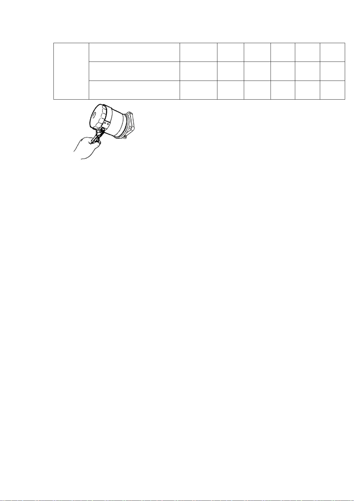
2.1.2 Replace oil filter element: Revolve down the oil filter element with a filter element spanner
in anticlockwise direction, clean the oil filter seat, smear a thin lube oil on the filter element
sealing gasket before replacing, revolve hard with hand in clockwise direction, then revolve 3/4
circle with filter element spanner.(Tighten torque valve20-23N.m)
2.1.3 Refill fuel, about 6.9L.
Run the engine 5 minutes to preheat the engine, and check for oil leakage. Recheck fuel after
stop running 10 minutes, and refill to the upper limit line.
After the initial maintenance, replace fuel and oil filter element regularly per 250h interval.
2.2 Check per 50h operation
2.2.1 Drain out fuel tank: Prepare an oil basin; revolve down the drain screw, drain out water and
other foreign matter in the fuel tank; install drain screw and tighten up, check for oil leakage.
2.2.2 Check battery: Disconnect battery negative electrode earth wire when checking the electric
appliance system, or fire will result by short circuit; Make sure to be well-ventilated, or hydrogen
caused during charging will burn; Check battery electrolyte and refill to the upper limit location if
it is gong to reach the lower one, otherwise life of battery will be shorten, or even explosion will
be caused. You should always check and refill distilled water since electrolyte lever drops down
quickly in summer. Please recharge the battery if rotation speed of crankshaft is slower than
normal and starting is failure. If you still can’t start the engine after recharging, replace the battery.
2.2.3 Clean air filter: Air filter element will easily be polluted by dust, oil mist or steam, which will
result in increase of intake resistance, decrease of intake volume, and black smoke of engine,
so you should always check and clean the oil filter element, or even replace it; Cleaning should
be more frequent if operating at
Fuel
injector
and fuel
injection
pump
Check and adjust fuel injection
pressure
○
Timing check and adjust of fuel
injection
○
Maintenance of fuel injector
and fuel injection pump
●

Picture 6 Clean air filter places full of dust(such as quarrying plant, coal yard
or road building plant), foreign matter inside the oil filter should be cleaned; Take out filter
element parts from air filter shell, blow dust down with compression air. Please replace filter
element parts if papery filter element is broken. Clean oil sludge inside the air filter; cover the air
inlet port with cloth to prevent some other matter dropping into the air inlet manifold.
2.2.4 Install the air filter, pay attention to the sealing condition between filter element and
connecting pipe to prevent air entering into cylinder not through filter element.
2.3 Check per 250h operation
2.3.1 Replace lube oil and filter element inside the oil filter, replace once per 250h operation from
the second time.
2.3.2 Check and clean radiator element: Dust and dirt adhesion on the radiator element will
reduce radiator’s cooling performance and result in engine’ overheat, you can advance the
cleaning according to special condition, or even clean it everyday; Flow down dust and dirt
around the radiator element with 196kPa(2kgf/cm2)compression air or even the lower air
pressure compression air. If there is still dirt, clean completely with detergent and water; Wear
protecting grasses to prevent dust or floating matter hurting your eyes before using compression
air; don’t try to clean radiator element with high pressure water tap and high pressure air, or try
to clean with brush, which will damage radiator element.
2.3.3 Replace air filter element: Damaged filter element will bring air enter into cylinder without
filtering, and accelerates wear of valve, cylinder, piston and piston ring. Dusty air filter element
will result in hard starting, power decrease and black smoke of engine.
2.4 Check per 500h operation
2.4.1 Replace fuel filter: Regularly replace diesel filter element before it is blocked by oil mist.
(1) Close oil tank switch, disassemble inlet/exhaust pipe, take out diesel filter element, and then
clean the fuel filter seat.
(2) Replace filter element, install the fuel filter.
(3) Install the fuel inlet/exhaust pipe, turn on oil tank switch, and drain out air in fuel line,
otherwise hard starting or stop running after starting will be resulted.
2.4.2 Replace cooling water: Drain out water after the cooling water is cooled down, in order to
prevent be scalded by the splashing hot water.
(1) Cooling water which contains iron rust or incrustation will deduce cooling performance, as
well as refrigerating fluid.
(2) Cooling water should be replaced at least once per year. Fill in soft water only after draining
out the cooling water.
2.4.3 Check and adjust valve clearance
Make sure that the valve is off, because only in that condition there will be valve clearance.
Notice: This single cylinder/double cylinder engine is marked from flywheel terminal to gearing
box terminal, which is different from the normal way. Upper dead point line for each cylinder is
marked on the flywheel; you can see them from the dead point view port hole on flywheel cover
(φ30). Upper dead point line for single cylinder is marked on engine body.
(1) Adjust valve clearance
a) Make sure the 1st cylinder piston is at the compression upper dead point, you can then
adjust the inlet/exhaust air clearance of the 1
st
cylinder 0.1mm;
b) Revolve flywheel 280° in anticlockwise direction after regulation, and adjust the
inlet/exhaust air clearance of 2
nd
cylinder 0.1mm;
Notice: Do remember tighten the adjusting screw cap tightly after regulation, otherwise it will
loosen soon and cause engine fail to work.
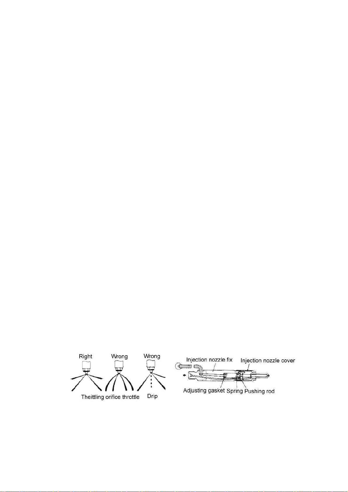
2.4.4 Check and adjust fuel injector: Check and regulation of fuel injecting pressure and injecting
mist quality should be operated on the fuel injecting experiment table.
(1) If the fuel injecting pressure is incorrect, please revolve down the fuel injecting parts fasten
cap, take out adjusting gasket and replace for a new one , so that the fuel injecting pressure
can attach to the correct valve(13±0.5)MPa.
(2)If the fuel injecting pressure is correct while the quality of injecting mist is poor, please clean
the injecting hole or replace the fuel injector parts;
(3)When installing fuel injector into the cylinder cover, please use the original fuel injecting
washer to make sure the fuel injecting head extend 2.2-2.3mm. Too big mistake will affect power,
fuel consumption or exhaust smoke of diesel engine.
2.5 Check per 1000h operation
2.5.1 Check and adjust the injection advance angle (please leave it to specialist, for this task
needs special tools, knowledge and skill).

a. Concrete steps
(1) Refill the fuel injection pump with fuel, and revolve the flywheel in clockwise direction to the
compression upper dead centre. Resolve the flywheel for several times until there is fuel flowing
out.
(2) Install the high pressure oil pipe tie which is used for measuring the oil supplying advance
angle, then resolve the flywheel to drain out the air inside. Stop the flywheel at 30° BTDC.
(3) Resolve the flywheel slowly in clockwise direction and check the oil level, stop the flywheel
immediately when oil begins fluctuating. The oil supplying advance angle is supposed to be 18.5°
±1°, if not, you should disassemble the fuel injection pump assembly, replace the adjust gasket,
check and adjust for another time until the value gets to 18.5°±1°.
(4) Screw on the fuel injection pump fixed bolt after adjusting and install the high pressure oil
pipe parts in turn.
Notice: Drain out the air in the high pressure oil pipe.
The rust and scale in the cooling system will worsen the heat abstraction performance and
increase the cooling water temperature. So please clean the rust and scale in the cooling system
by professional.
2.6 Check per 2000h running
2.6.1 Check and replace fuel、lube oil、cooling water and rubber hose. Check each kind of rubber
hose regularly; replace them if there is damage or aging.
2.6.2 Check and grind sealing ring belt of intake/exhaust valve. Please consult with the specialist
because professional skill is needed. You should check the sinking quantity of air door, width of
sealing ring belt and clearance between valve stem and valve pipe.
2.6.3 Check performance of fuel injection pump, this job needs oil pump experiment table, so
please consult with the specialist to maintain. You should check aiming point oil supply quantity,
starting oil quantity, oil supply uniformity of each cylinder, governor, maximum and minimum
stable rotation limit.
Disassembly and reassembly of diesel engine
1. Basic procedure of disassembly
(1) Prepare necessary room or container to store parts before disassembly, put each kind of bolt
and screw as well as related parts together, in order to prevent possible mistaken.
(2) Make sure what problem there is before disassembling; avoid mistaken disassembly.
1.1 Disassemble muffler weldment
(1) Loosen the four M8 nuts which fix the muffler weldment.
(2) Remove the muffler weldment from the cylinder cover.
Refer to picture 11
picture 11
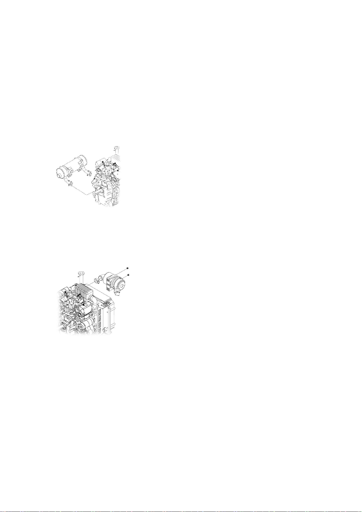
1.2 Disassembly the air filter assembly
(1) Loosen the two M8 nuts which fix the air filter seat.
(2) Loosen the hoop of the connection hose.
(3) Remove the air filter assembly.
Refer to picture 12
picture 12
1.3 Disassemble the heat abstraction water tank and overflow tank parts
(1) Loosen the four M8X10 bolts and nuts which fix the heat abstraction water tank parts
(2) Loosen the hoop which fixes the inlet/outlet hose of heat abstraction water tank
(3) Remove the heat abstraction water tank parts
(4) Remove the overflow tank.
Refer to picture 13
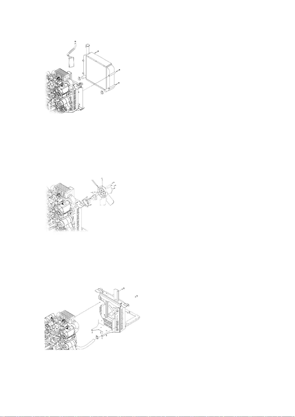
picture 13
1.4 Disassemble fan gasket、fan impeller and fan seat
(1) Loosen the four M6×25 bolts, which fix fan impeller and fan gasket and then remove the fan
impeller and fan gasket.
(2) Loosen the three M6×16 bolts which fix fan seat and then remove the fan seat.
Refer to picture 14
picture 14
1.5 Disassembly the air conduct cover parts
(1) Loosen the three M10X20 bolts which fix the air conduct cover parts on the flywheel end.
(2) Loosen the four M6X16 bolts which fix the air conduct cover parts on the engine seat.
(3) Remove the air conduct cover parts
Refer to picture 15
picture 15
1.6 Disassemble the inlet pressurizer tank
(1) Loosen the four M6X18 bolts which fix the inlet pressurizer tank parts on the cylinder cover
 Loading...