

Page 1

KIP Graphics Pro
KIP Graphics Pro Installation and User Guide
No part of this publication may be copied, reproduced or distributed in any form without express written permission
from KIP. 2015 KIP. v1.
- 1 -
Page 2

KIP Graphics Pro
Contents
Introduction .............................................................................................................................................................. 6
System Requirements ........................................................................................................................................ 6
Operating Systems ............................................................................................................................................ 6
Installation ................................................................................................................................................................. 7
Installation of the Program ............................................................................................................................... 7
KIP Color RIP.client Login ...................................................................................................................................... 10
Keycode Entry ........................................................................................................................................................ 11
Hardware Configuration ....................................................................................................................................... 12
Hardware .......................................................................................................................................................... 12
Add Printer ........................................................................................................................................................ 12
Printer Configuration ....................................................................................................................................... 13
Delete Printer .................................................................................................................................................... 13
The single Configuration Dialogs ................................................................................................................... 13
The Configuration Wizard ............................................................................................................................... 14
NAME / CONNECTION ................................................................................................................................................... 14
PLACEMENT ............................................................................................................................................................... 14
TECHNICAL LABEL ........................................................................................................................................................ 16
CONFIGURATION / LOADED CONSUMABLES ......................................................................................................................... 17
DEFINE MEDIA LIST ...................................................................................................................................................... 18
DEFAULT SETTINGS FOR PRINT OPTIONS ............................................................................................................................. 19
POSTSCRIPT ............................................................................................................................................................... 22
CALIBRATION ............................................................................................................................................................. 23
Create Queue .................................................................................................................................................. 29
TAB GENERAL ............................................................................................................................................................. 29
QUEUE ..................................................................................................................................................................... 29
TAB ADVANCED .......................................................................................................................................................... 31
TAB QUEUES .............................................................................................................................................................. 32
TAB HPGL ................................................................................................................................................................ 33
Menu Bar Options .................................................................................................................................................. 34
File ..................................................................................................................................................................... 34
Configuration ................................................................................................................................................... 34
Hardware .......................................................................................................................................................... 35
Calibration ........................................................................................................................................................ 35
Pause Unattend / Resume Unattend ............................................................................................................. 35
Preferences ...................................................................................................................................................... 35
Tab General ..................................................................................................................................................... 36
PAPER FORMAT ........................................................................................................................................................... 36
UNIT ....................................................................................................................................................................... 36
SIMPLE FILTER EDITOR BY DEFAULT FOR RIP ......................................................................................................................... 36
USE SCREEN ICC PROFILE .............................................................................................................................................. 37
SHOW WARNING FOR DEMO VERSION .................................................................................................................................. 37
SHOW WARNING WHEN CONFIGURATION CHANGES .................................................................................................................. 37
SHOW WARNING WHEN UNSAVED CHANGES WILL BE DELETED...................................................................................................... 37
No part of this publication may be copied, reproduced or distributed in any form without express written permission
from KIP. 2015 KIP. v1.
- 2 -
Page 3

KIP Graphics Pro
START NEW JOB AFTER SUBMIT ......................................................................................................................................... 37
JOB NUMBER IN PRINTER DISPLAY ....................................................................................................................................... 37
USE COMPRESSED TRANSFER ............................................................................................................................................ 38
Tab Explorer Window....................................................................................................................................... 38
SHOW FILTERS ............................................................................................................................................................ 39
LOG IN … ................................................................................................................................................................. 39
View .................................................................................................................................................................. 40
LARGE ICONS ............................................................................................................................................................. 40
SMALL ICONS ............................................................................................................................................................. 40
LIST ........................................................................................................................................................................ 40
DETAILS.................................................................................................................................................................... 40
SHOW BUTTON CAPTION ................................................................................................................................................ 40
THUMBNAILS .............................................................................................................................................................. 40
PREVIEW ................................................................................................................................................................... 40
REFRESH ................................................................................................................................................................... 40
Edit ..................................................................................................................................................................... 41
SELECT ALL ................................................................................................................................................................ 41
SELECT NONE ............................................................................................................................................................. 41
INVERT SELECTION ....................................................................................................................................................... 41
Actions .............................................................................................................................................................. 41
Info .................................................................................................................................................................... 41
ABOUT ..................................................................................................................................................................... 42
JOB MONITOR ............................................................................................................................................................. 42
UPLOAD LOCAL FILTERS TO KIP ....................................................................................................................................... 42
HELP ....................................................................................................................................................................... 42
TAB GENERAL ............................................................................................................................................................. 44
SCALING / POSITION .................................................................................................................................................... 44
TAB OUTPUT OPTIONS .................................................................................................................................................. 48
TAB PANELING ............................................................................................................................................................ 49
TAB HPGL ................................................................................................................................................................ 52
PEN SETTINGS ............................................................................................................................................................ 52
USER PEN SETTINGS ..................................................................................................................................................... 52
CHANGE PEN COLOR .................................................................................................................................................... 53
SAVE / LOAD PEN PARAMETERS ....................................................................................................................................... 53
PREVIEW ................................................................................................................................................................... 53
Viewer/Editor ................................................................................................................................................... 54
LOAD FILE ................................................................................................................................................................. 55
SAVE FILE .................................................................................................................................................................. 55
PRINT IMAGE .............................................................................................................................................................. 55
UNDO LAST ACTION (CTRL +Z) ...................................................................................................................................... 55
SHOW/HIDE SPY WINDOW ............................................................................................................................................. 55
ZOOM OPTIONS .......................................................................................................................................................... 56
ZOOM TO WINDOW SIZE ................................................................................................................................................ 56
SCALE IMAGE.............................................................................................................................................................. 56
HORIZONTAL MIRROR ................................................................................................................................................... 57
VERTICAL MIRROR ....................................................................................................................................................... 57
No part of this publication may be copied, reproduced or distributed in any form without express written permission
from KIP. 2015 KIP. v1.
- 3 -
Page 4

KIP Graphics Pro
ROTATE BY 90° CCW .................................................................................................................................................... 57
INVERT IMAGE ............................................................................................................................................................ 57
DESPECKLE ................................................................................................................................................................ 58
SWITCH TO ZOOM MODE ............................................................................................................................................... 59
SWITCH TO PAN MODE .................................................................................................................................................. 59
2-POINT DESKEW ........................................................................................................................................................ 59
CROP RECTANGLE AREA ................................................................................................................................................ 59
INSERT TEXT .............................................................................................................................................................. 60
ERASE AREA ............................................................................................................................................................... 60
Preview ............................................................................................................................................................. 60
RIP PREVIEW .............................................................................................................................................................. 61
SELECT AN AREA ......................................................................................................................................................... 61
RESET AOI SETTING ..................................................................................................................................................... 62
ZOOM TO AOI/CROPPING ............................................................................................................................................. 62
ZOOM IN .................................................................................................................................................................. 62
ZOOM OUT................................................................................................................................................................ 62
APPLY FILTERING ......................................................................................................................................................... 62
SHOW GAMUT WARNING................................................................................................................................................ 63
SOFTPROOF ............................................................................................................................................................... 63
Job Editor .......................................................................................................................................................... 63
Speed Buttons within Job Edit or ..................................................................................................................... 63
ADD FILE(S) ............................................................................................................................................................... 64
DELETE ..................................................................................................................................................................... 64
LOAD JOB .................................................................................................................................................................. 64
INSERT JOB ................................................................................................................................................................ 64
SAVE JOB .................................................................................................................................................................. 64
START NEW JOB .......................................................................................................................................................... 64
RELOAD JOB ............................................................................................................................................................... 64
Options of the Job Editor ................................................................................................................................ 66
COMPOSING AND PRINT ORDER ....................................................................................................................................... 66
Prefligth ............................................................................................................................................................. 66
Edit Pictures and Output ................................................................................................................................. 66
TAB GENERAL ............................................................................................................................................................. 66
TAB ADVANCED .......................................................................................................................................................... 70
TAB PANELING ............................................................................................................................................................ 70
TAB HPGL ................................................................................................................................................................ 74
PEN SETTINGS ............................................................................................................................................................ 74
USER PEN SETTINGS ..................................................................................................................................................... 74
CHANGE PEN COLOR .................................................................................................................................................... 74
SAVE / LOAD PEN PARAMETERS ....................................................................................................................................... 75
PREVIEW ................................................................................................................................................................... 75
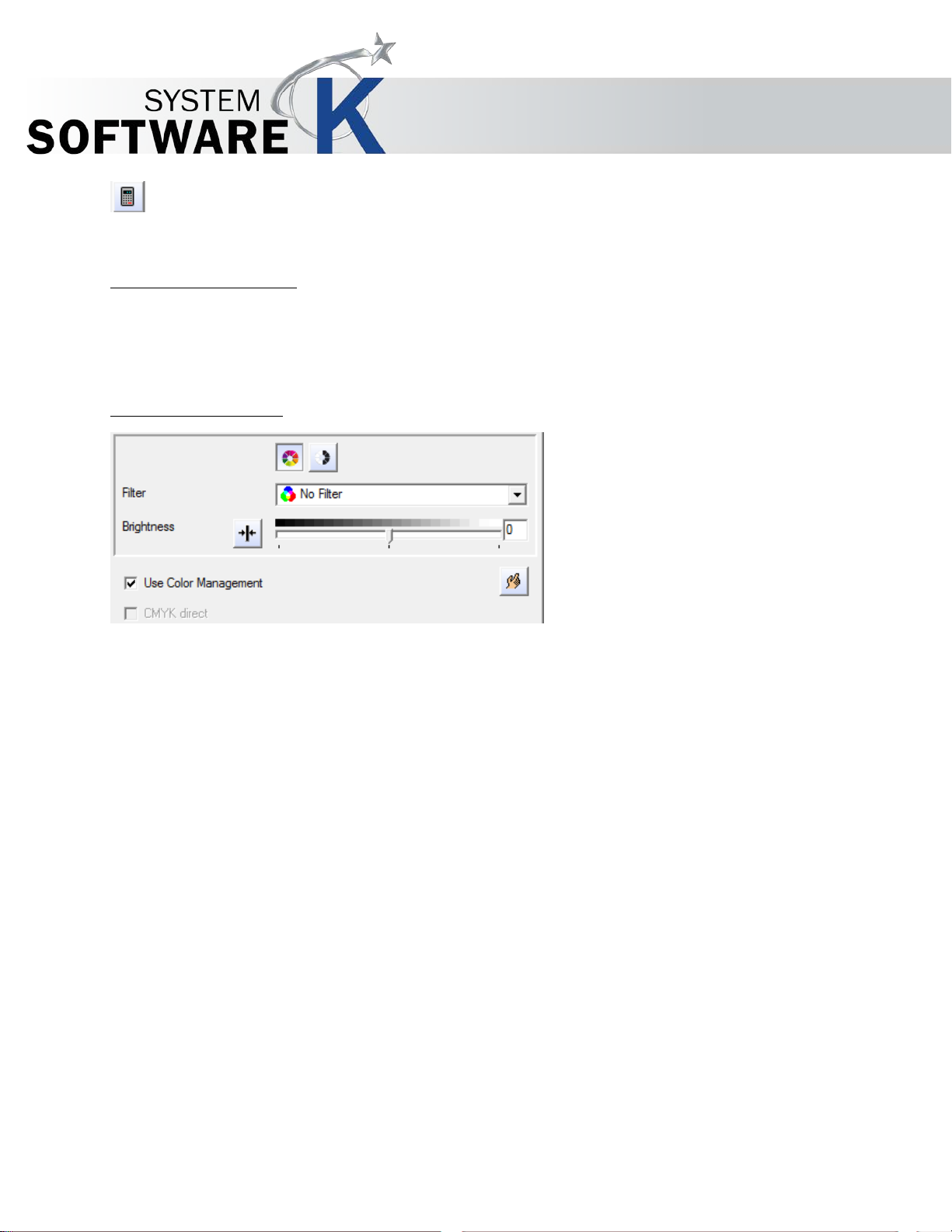
Filter Editor ............................................................................................................................................................... 75
Functions and Structure of the Filter Editor ................................................................................................... 76
PREVIEW (OF THE FILTER EDITOR) ..................................................................................................................................... 77
HISTOGRAM ............................................................................................................................................................... 78
TAB BLACK AND WHITE POINTS (COLOR MODE WITHOUT COLOR MANAGEMENT) ........................................................................... 78
No part of this publication may be copied, reproduced or distributed in any form without express written permission
from KIP. 2015 KIP. v1.
- 4 -
Page 5

KIP Graphics Pro
TAB POSTPROCESSING (BLACK & WHITE MODE) .................................................................................................................... 81
TAB GAMMA CORRECTION (COLOR MODE WITHOUT COLOR MANAGEMENT) ................................................................................. 82
TAB ENHANCEMENT (COLOR MODE WITH COLOR MANAGEMENT) .............................................................................................. 83
TAB SPECIAL FILTER (ALL MODES
TAB COLOR ADJUST (COLOR WITH COLOR MANAGEMENT) ....................................................................................................... 87
TAB COLOR EXCHANGE (COLOR WITH COLOR MANAGEMENT) ................................................................................................... 88
SIMPLE FILTER EDITOR (TAB GAMMA CORRECTION) ............................................................................................................... 89
KIP Color RIP.monitor ............................................................................................................................................. 90
Tab Jobs ............................................................................................................................................................ 90
JOB SELECTION ........................................................................................................................................................... 91
BUTTON COMMANDS .................................................................................................................................................... 91
Tab Printers/Queues ........................................................................................................................................ 92
Tab Connection ............................................................................................................................................... 93
Menu Options .................................................................................................................................................. 93
KEYCODE .................................................................................................................................................................. 94
JOB DATABASE ............................................................................................................................................................ 94
UNIT ....................................................................................................................................................................... 95
KIP Color RIP.hotfolder ........................................................................................................................................... 96
Hotfolder Configuration .................................................................................................................................. 97
ADD HOTFOLDERS ....................................................................................................................................................... 97
EDIT ........................................................................................................................................................................ 97
DELETE ..................................................................................................................................................................... 97
FTP-TIMEOUT AFTER FILE COMPLETION .............................................................................................................................. 98
KIP Color RIP.backup ............................................................................................................................................. 98
EXCEPT
BLACK & WHITE MODE) ............................................................................................. 84
No part of this publication may be copied, reproduced or distributed in any form without express written permission
from KIP. 2015 KIP. v1.
- 5 -
Page 6

KIP Graphics Pro
Introduction
KIP Color RIP software is a comprehensive color printing and color management software for use at a PC
workstation. KIP Color RIP features professional grade imaging feature set with automatic modes and fine
controls. The software provides advanced color management features, image editing capabilities, paneling of
images for outdoor gra phics, nesting of images for optimum media us age and much more. A suite of image
editing and manipulation tools allow you to adjust margins, scale and orientation, or make on-the-fly
alterations to image content.
Integrates with single or multiple printers
Color RIP system for graphic files
Color RIP system for technical files
Advanced color controls
System Requirements
For KIP Color RIP we recommend:
• Dual core desktop CPU or higher
• 4 GB RAM
Operating Systems
We recommend Windows 7.
No part of this publication may be copied, reproduced or distributed in any form without express written permission
from KIP. 2015 KIP. v1.
- 6 -
Page 7
KIP Graphics Pro
Installation
Installation of the Program
Insert the KIP Software CD into the CD/DVD-ROM drive and exit all other applications. Setup will continue automatically in case the
Autostart function is active in the operating system. If Autostart is not active, double click on S
CD/DVD to initiate the installation process.
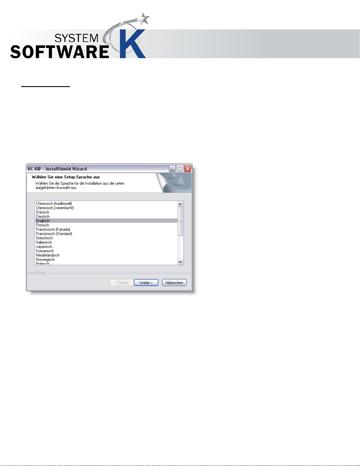
Choose setup language.
ETUP.EXE from the installation
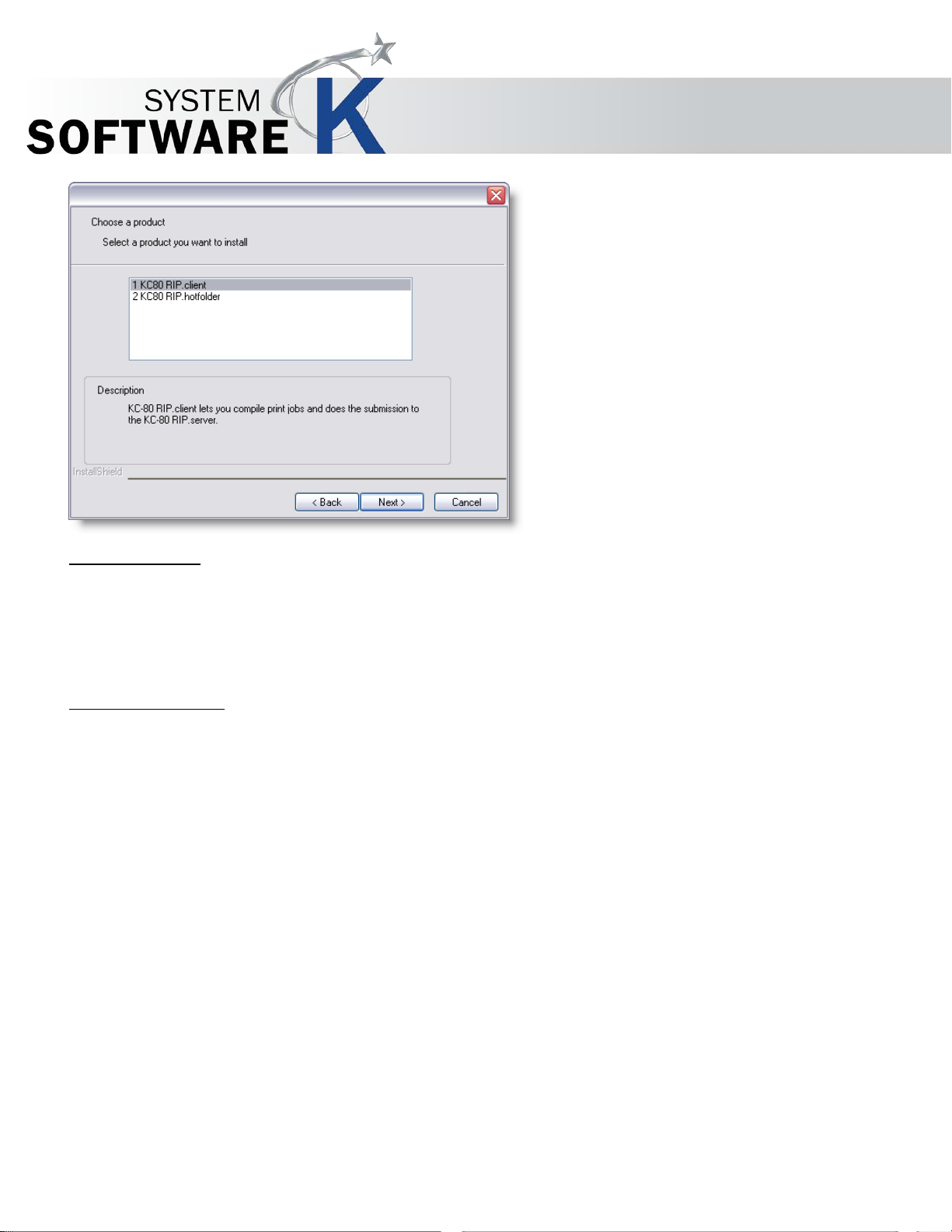
The Welcome screen is displayed. Click on the N
A menu showing multiple program choices is displayed. Users can pick the programs intended for installation.
No part of this publication may be copied, reproduced or distributed in any form without express written permission
from KIP. 2015 KIP. v1.
EXT button.
- 7 -
Page 8
KIP Graphics Pro
KIP Color RIP.client
Choosing this option will only install the client version of KIP Color RIP. Thus, KIP Color RIP.clients need network access to a KIP
Color controller providing the KIP Color RIP.server.
KIP Color RIP.client is the basic program to work with images/pictures and to print them. Additionally it is needed to customize your
KIP Color RIP network to your demands. Changing the server-configuration will ask for sufficient rights.
KIP Color RIP.hotfolder
Highlight this option to install only KIP Color RIP.hotfolder on your syste m.
By using the hotfolder-program you can create special print folders on your system. The hotfolders will execute print jobs with
associated queues or printer clusters and its printers if printable files are put into those folders. This allows easy and quick printing
management and capability.
No part of this publication may be copied, reproduced or distributed in any form without express written permission
from KIP. 2015 KIP. v1.
- 8 -
Page 9
KIP Graphics Pro
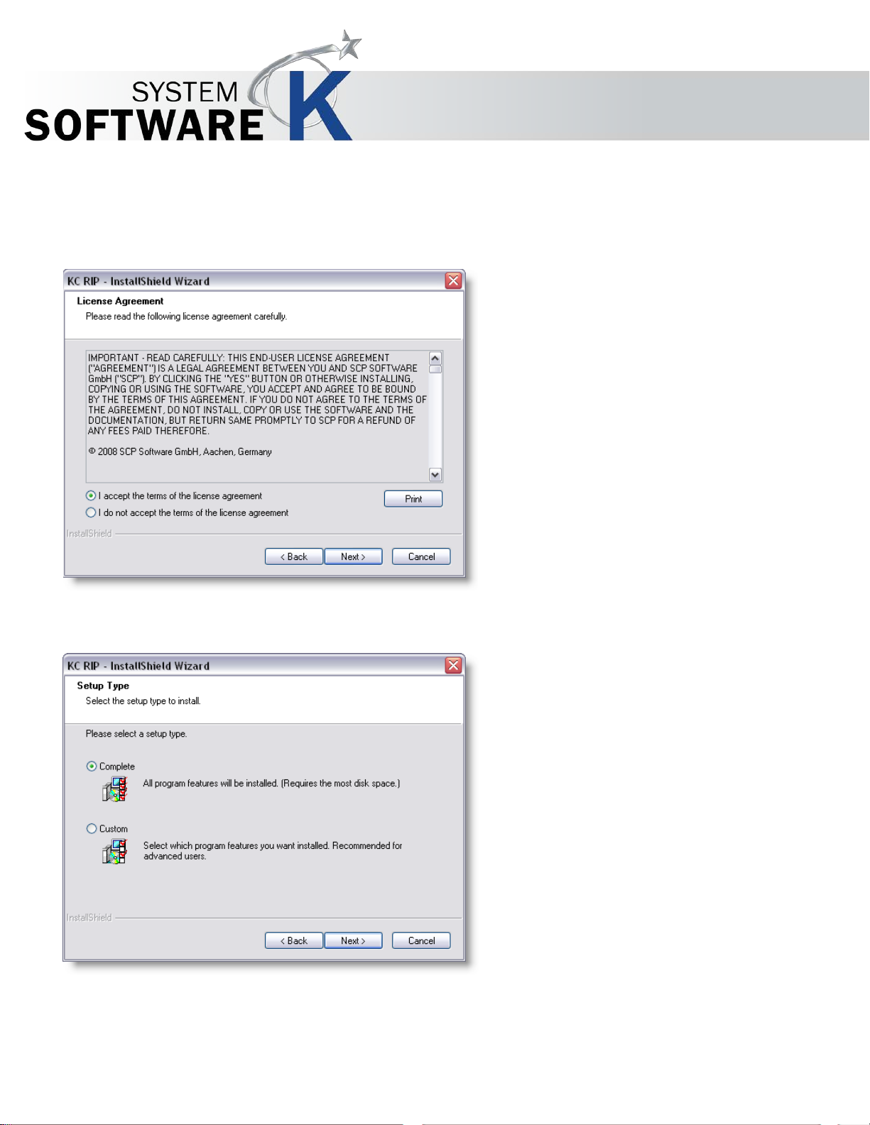
After selecting the desired program, you then have to accept the license agreement by selecting the corresponding radio button
option in order to continue the installation. To get a print out version of the same license agreement as displayed, click the PRINT
button.
If you do not accept the terms of the license agreement, the installation process will be terminated.
After having accepted the license agreement, you then have to select a setup type by activating the corresponding radio button. You
can select among C
OMPLETE and CUSTOM.
If you pick CUSTOM, you then have the choice to define the installation location of the program. Click CHANGE to provide a
destination location of the program.
You may then also alter the standard system location for print data.
No part of this publication may be copied, reproduced or distributed in any form without express written permission
from KIP. 2015 KIP. v1.
- 9 -
Page 10
KIP Graphics Pro
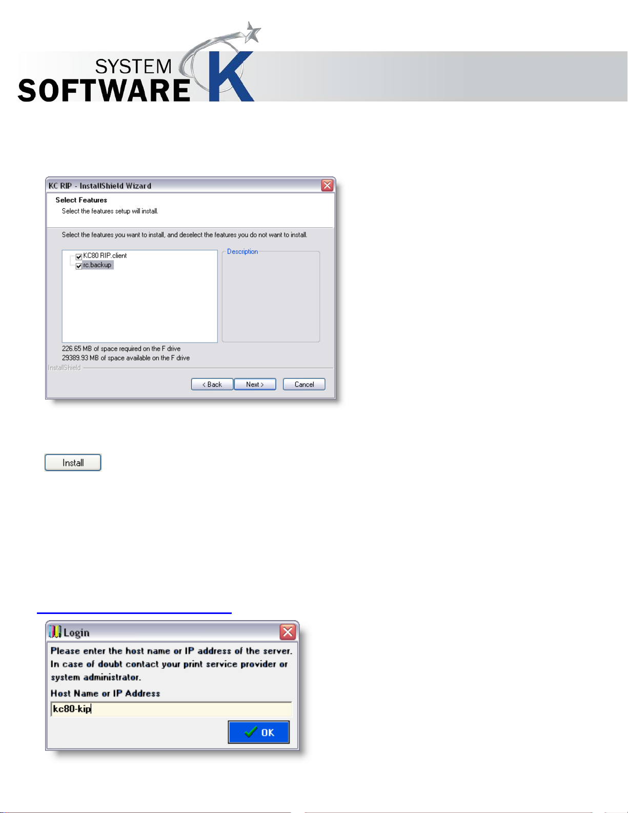
If you have opted for the C
each box belonging to the desired feature or remove a checkmark to avoid installation of that feature. The selections may differ
depending on the product(s) you are going to install.
USTOM setup, you will be further prompted to select the features you want to install. Put a checkmark at
You then have to enter the correct (DNS-) name of the KIP Color controller and its port. If KIP Color RIP.server has not changed the
standard port, it ought to be port 9683.
Press the I
Now the actual installation process begins. Click C
INISH to complete the setup program after successful installation.
Click F
Now you can start the software from the desktop with the program icon and from the start menu.
Confirm that the Windows user accounts have full access to the parameters folder.
This is the folder for the print data you have set during the installation.
To be granted further rights please ask your system administrator.
NSTALL-button to start installation of the program.
ANCEL to stop the installation process.
KIP Color RIP.client Login
No part of this publication may be copied, reproduced or distributed in any form without express written permission
from KIP. 2015 KIP. v1.
- 10 -
Page 11

KIP Graphics Pro
User will be prompted to enter the IP Address of a KIP Color Controller (KIP Color RIP.server).
In case of doubt please contact your system administrator.
Keycode Entry
You will notice a small WARNING! Window appearing with the first start telling the program is currently running in demo mode.
Features are reduced and restricted until a correct Keycode is entered and the program (and its server) is restarted. If you do not
want to see the demo warning again, just activate the D
In order to activate the full version of KIP Color 80 RIP.client, please follow instructions in this section:
• Obtained the additional Keycode from KIP.
• Go to the menu bar of the KIP Color RIP.client main window and click on I
• Select J
• The KIP Color RIP.monitor appears consequently.
• Open the menu bar entry MENU and select CONFIGURATION.
• Under
• When you are ready, click on A
If the key code is valid and correct, all functions are now availabl e.
If the key code is invalid or incorrect, the field will become red after clicking on A
in the demo-mode.
To learn more about all the different features of the KIP Color RIP.monitor go to §
OB-MONITOR.
KEYCODE you will find a text field where to enter your keycode.
PPLY. KIP Color RIP.server will restart subsequently.
ON’T SHOW THIS MESSAGE ANYMORE check box.
NFO.
PPLY. The program will not be restarted and remains
KIP COLOR RIP.MONITOR.
No part of this publication may be copied, reproduced or distributed in any form without express written permission
from KIP. 2015 KIP. v1.
- 11 -
Page 12
KIP Graphics Pro
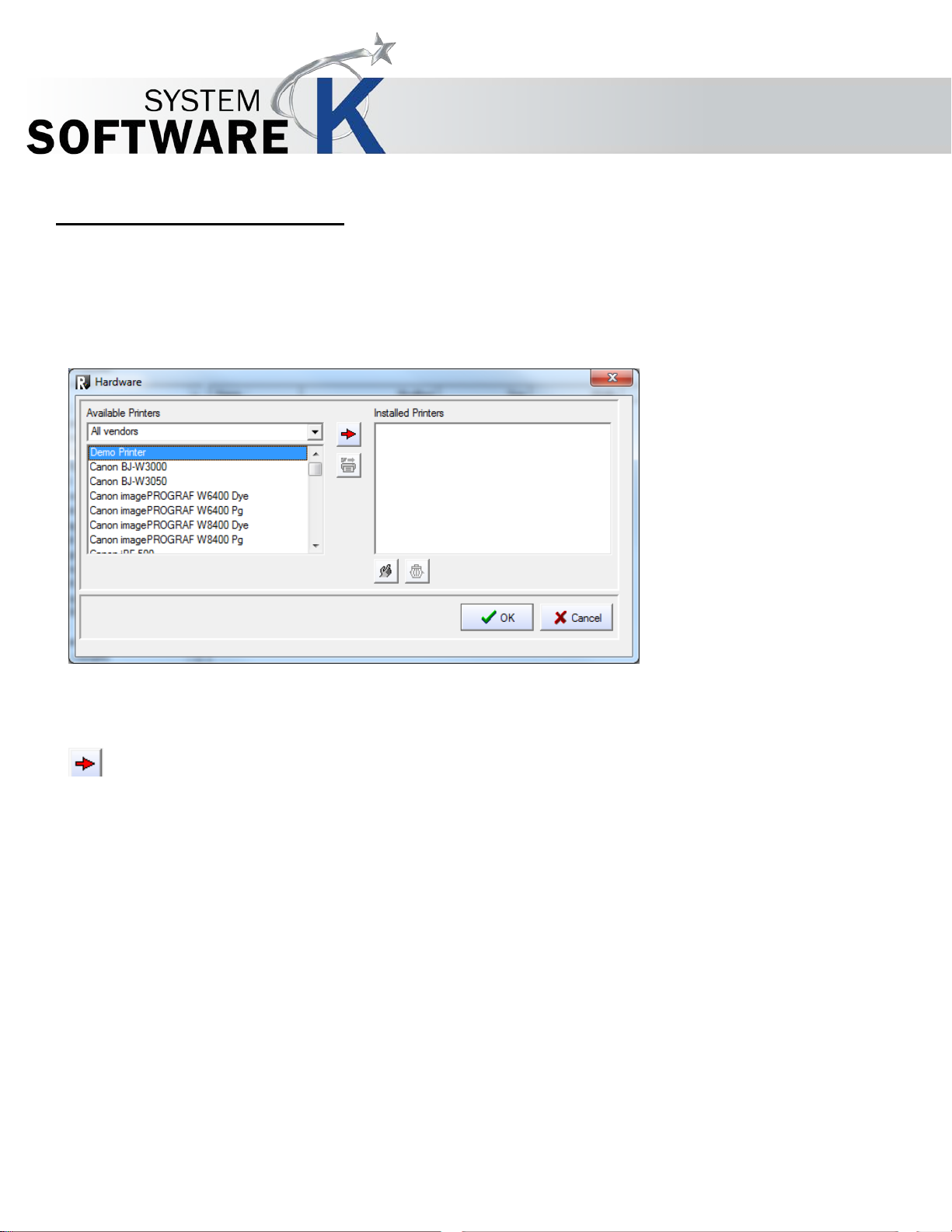
Hardware Configuration
Hardware
The window HARDWARE will appear automatically at the first start. Later on, go to menu bar CONFIGURATION
open the same window (see § KIP COLOR RIP.CLIENT MENU BAR OPTIONS
§ CONFIGURATION).
HARDWARE to
Add Printer
Highlight a printer in the list box AVAILABLE PRINTERS and click on the red arrow button (ADD PRINTER). Alternatively, you
can double-click on the printer.
After selecting a printer, you will automatically be guided to T
HE CONFIGURATION WIZARD.
No part of this publication may be copied, reproduced or distributed in any form without express written permission
from KIP. 2015 KIP. v1.
- 12 -
Page 13
KIP Graphics Pro
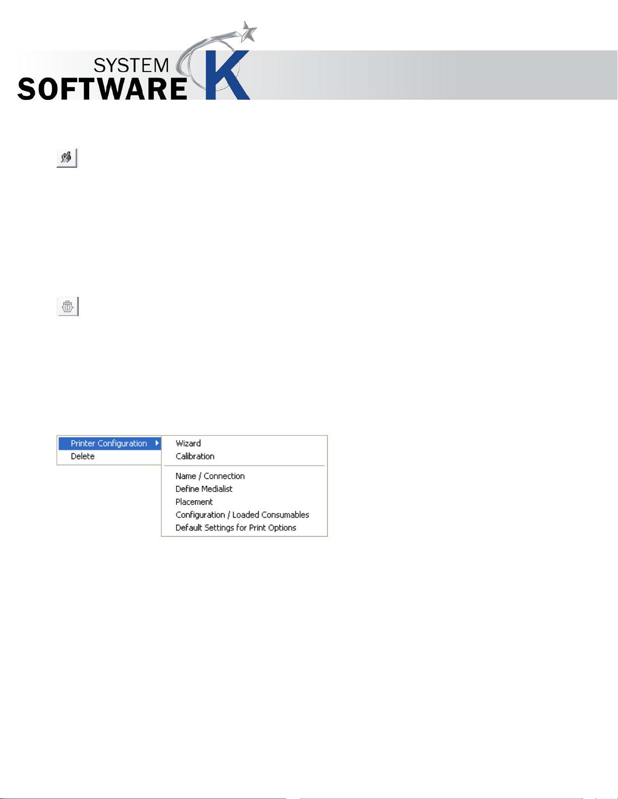
Printer Configuration
Clicking on the PRINTER CONFIGURATION button while an installed printer is highlight ed w ill open THE CONFIGURATION
WIZARD. You may also double-click on the printer to do the same.
In case of a highlighted queue the C
action.
For further details configuring a queue please go to C
Delete Printer
If you want to remove one printer, highlight the printer in question under INSTALLED PRINTERS and click the DELETE
PRINTER button (or click DELETE within the context menu that appears after right-clicking on an installed printer).
You will need the D
If a printer is in use for a queue, it cannot be deleted: you have to erase the queue that is using the printer in question first.
ELETE button in order to erase installed queues.
ONFIGURE QUEUE window will open. You can also use a double-click to perform the same
REATE QUEUE within this chapter.
The single Configuration Dialogs
Right-click on a printer under INSTALLED PRINTERS, highlight PRINTER CONFIGURATION and select the needed configuration
dialog from the context menu:
By using WIZARD you will rerun THE CONFIGURATION WIZARD for the selected printer.
No part of this publication may be copied, reproduced or distributed in any form without express written permission
from KIP. 2015 KIP. v1.
- 13 -
Page 14
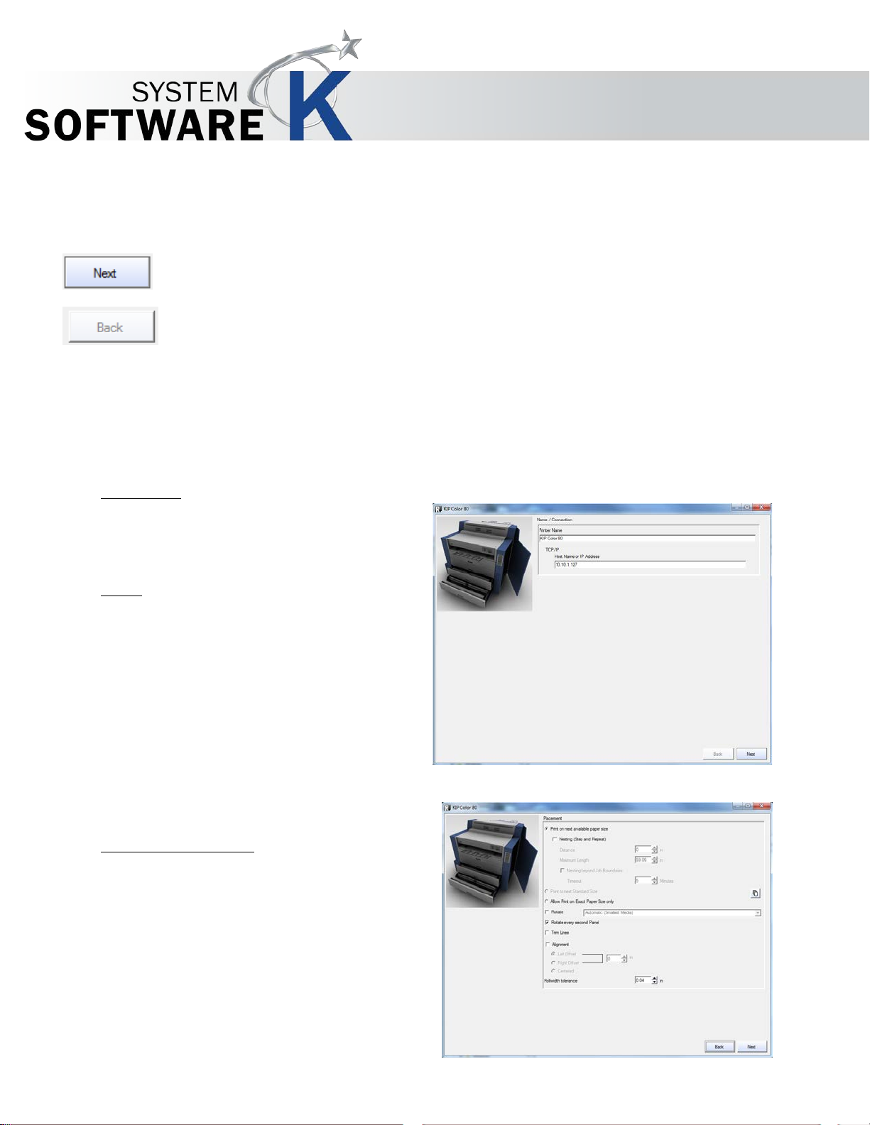
Printer Name
TCP/IP
Define output paper size
KIP Graphics Pro
The Configuration Wizard
The Configuration Wizard guides you through the configuration and calibration of your printers. Generally, you always have both of
the following buttons available in every configuration dialog:
You get from one dialog into the other via NEXT.
Back will bring you back to the previous dialog.
Name / Connection
This text field allows you to change the name of the
printer.
Type in the TCP/IP address of your printer or use the
H
OST NAME of the printer.
When all settings are made, click on N
The role configuration of the printer is now checked and
included calibration profiles libraries are installed. During the
following calibration you can also search for additional profiles on
your hard drive or CD. You will then automatically get to the
window P
LACEMENT.
EXT.
Placement
First you may choose among the radio buttons whether the
printer is allowed to P
PAPER SIZE, PRINT TO NEX T STANDARD SIZE or the
printer is allowed to
SIZE.
Before you can choose P
you need to define the allowed rollwidth by clicking on the
button right side from P
SIZE.
To use N
AVAILABLE PAPER SIZE , the following options will be
available then:
ESTING you need to choose PRIN T ON NEXT
RINT ON NEXT AVAILAB LE
ALLOW PRINT ON EXACT PAPER
RINT TO NEXT STANDARD SIZE
RINT TO NEXT STANDARDR
No part of this publication may be copied, reproduced or distributed in any form without express written permission
from KIP. 2015 KIP. v1.
- 14 -
Page 15

Rotate
Rotate every second Panel
Alignment
Trim Lines
You may now select TRIM LINES which will appear between each print of the same paper output. They will help you to cut
these prints manually.
Nesting
If you want to print several copies, and at least two copies fit into the print width, enable NEST MULTIPLE COPIES to have
the copies automatically printed next to each other. By selecting N
KIP Graphics Pro
ESTING more options become available:
Distance
You can determine the size of the area between copies under DISTANCE.
Maximum Length
Define the maximum length of nested copies.
Nesting beyond job boundaries
Activate this option to allow nesting of two or more print jobs on one paper output.
Timeout
If you have selected NESTING BEYOND JOB BOUNDARIES, you may further set the time interval KIP
Color RIP waits for another jobs to be nested before printing.
Finally, within the PLACEMENT dialog you have got these last options ROTATE, ALIGNMENT and ROLLWIDTH TOLERANCE in
order to apply further settings to the output:
Without a checkmark at this option pictures are printed with their standard rotation determined by the document.
If you check this option, you may choose among different rotations-types to be found in the drop down list:
When using AUTOMATIC (PAPER SAVE), the copy will be rotated so that paper can be saved during output.
If you want the output to be rotated without paper-save function, enter a rotation degree. They are arranged clockwise.
In order to rotate every second panel (you need to set up panel printing first) on the print out, e.g. to save paper media, you
need this option being activated.
Select the corresponding radio buttons if you want to have a LEFT or RIGHT OFFSET on your print out. Alter the size of the
offset to determine the distance between the paper side’s border and image.
No part of this publication may be copied, reproduced or distributed in any form without express written permission
from KIP. 2015 KIP. v1.
- 15 -
Page 16
Rollwidth tolerance
KIP Graphics Pro
Select the C
If case of left and right alignment you can also specify the offset.
If you want to allow print sizes that exceed the print width of your printer, you may define a new tolerated width. Please bear in
mind that this may cause a loss of certain areas of the image (first and foremost at the width borders).
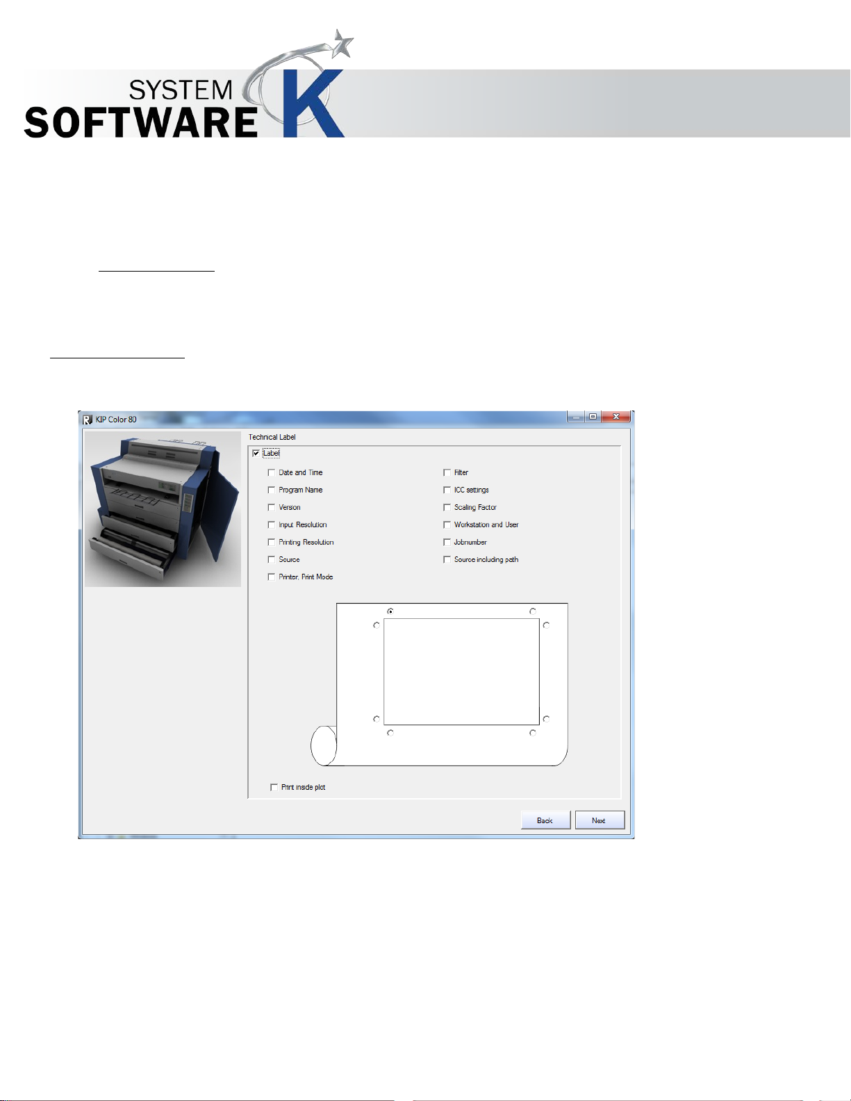
Technical Label
This option will cause an appearance of a LABEL on each copy. Labels are shown close to the copy and inform about various
settings.
ENTERED-radio button in order to set the image to the central instead.
You can determine which piece of information the standard label will include by checking the corresponding boxes.
Additionally, you may determine where the labels will appear on the print out. Just activate one radio button which represents the
place where the label will appear. If you want the label to be printed inside the image, activate the P
radio buttons will now appear inside the rectangle representing the position where the label will be printed on the picture.
RINT INSIDE PLOT box: the
No part of this publication may be copied, reproduced or distributed in any form without express written permission
from KIP. 2015 KIP. v1.
- 16 -
Page 17
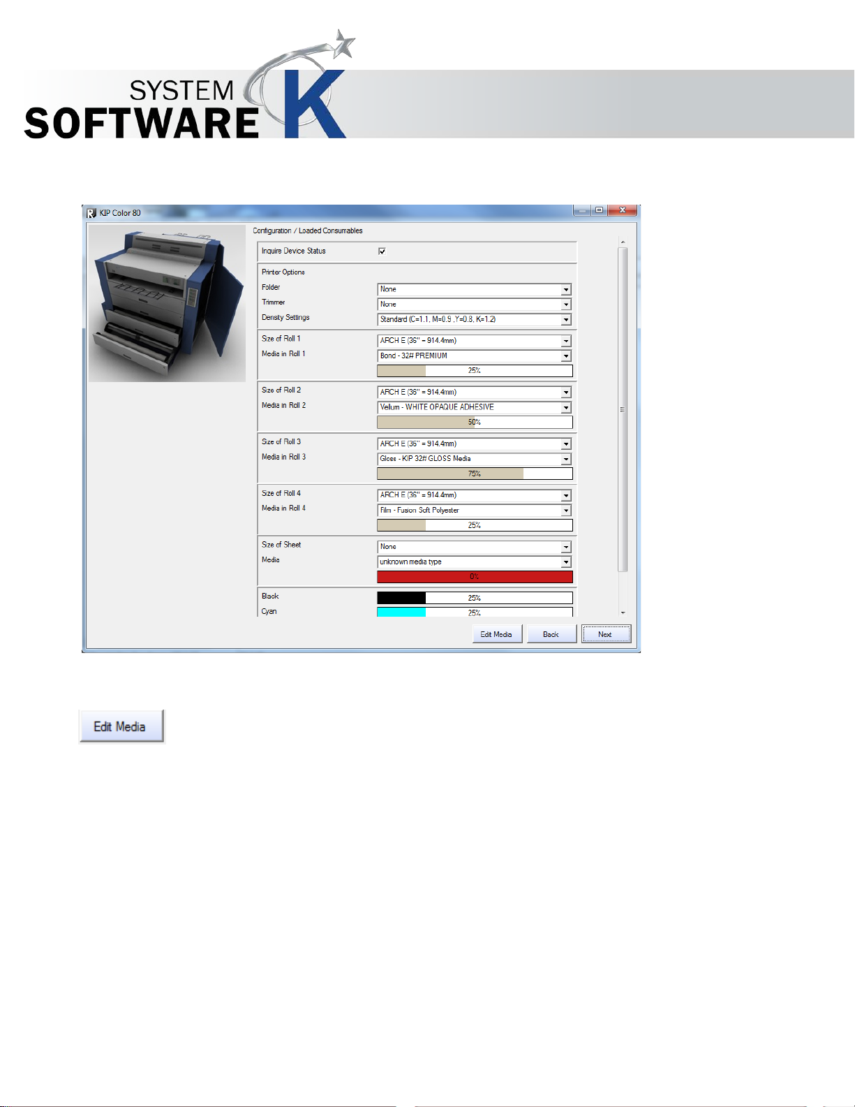
Configuration / Loaded Consumables
KIP Graphics Pro
The settings are media a nd de v ice-dependent, you have to select the paper types and ink types set in the printer.
Printers can be equipped with different numbers of paper rolls. You may also check the ink and media level.
You get to the dialog DEFINE MEDIA LIST via the button EDIT MEDIA. The dialog is explained below.
If you do not use original media, edit the medium/media you use via E
for original media only.
DIT MEDIA. This is important as the color profiles are made
No part of this publication may be copied, reproduced or distributed in any form without express written permission
from KIP. 2015 KIP. v1.
- 17 -
Page 18
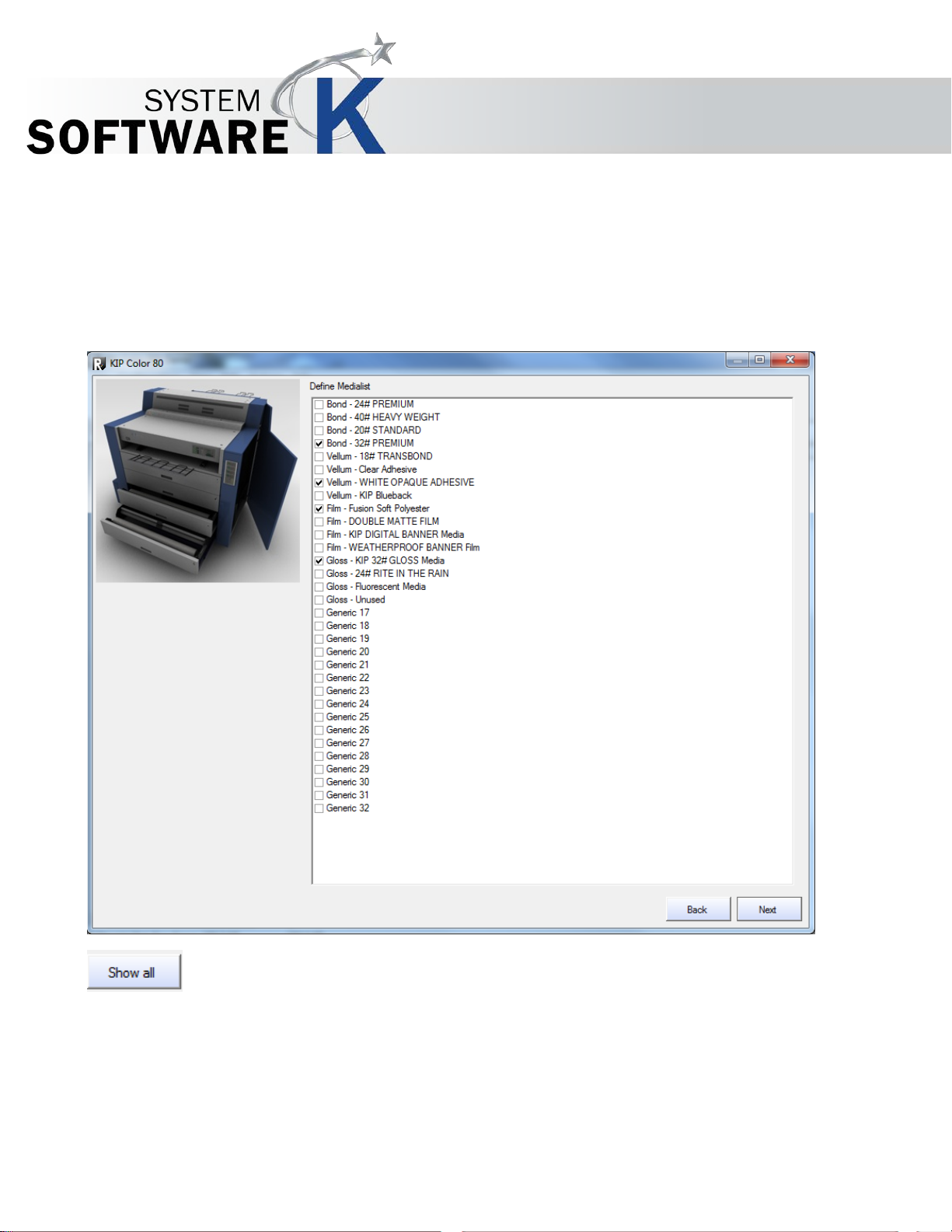
Define Media List
KIP Graphics Pro
You get to this dialog automatically with THE CONFIGURATION WIZARD, but also by using the HARDWARE window by
opening the right-click context menu of an installed printer and selecting P
by clicking the button EDIT MEDIA in the configuration dialog CONFIGURATION / LOADED CONSUMABLES.
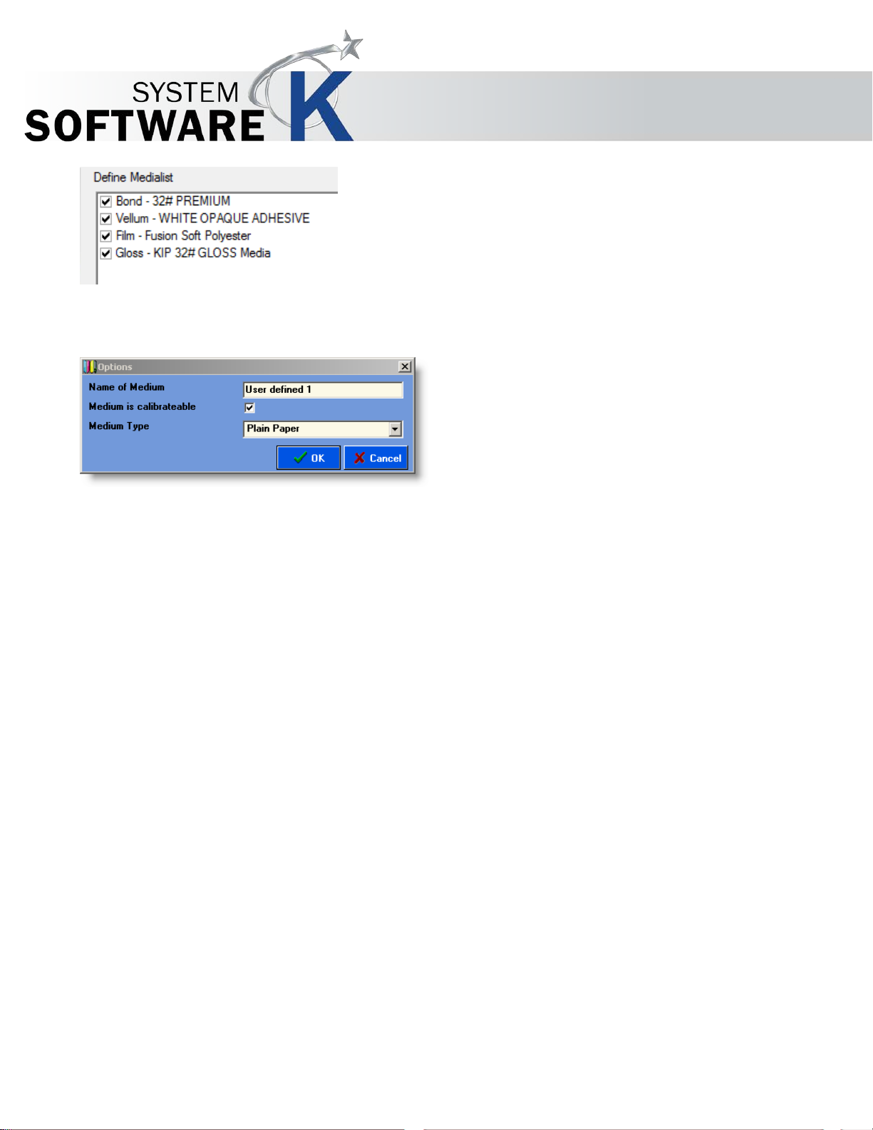
To get a list of all medium types and edit user-d efin ed med ia, click S
No part of this publication may be copied, reproduced or distributed in any form without express written permission
from KIP. 2015 KIP. v1.
- 18 -
RINTER CONFIGURATION DEFINE MEDIA LIST, or
HOW ALL.
Page 19
KIP Graphics Pro
Select the paper types you want to work with. If you do not use original paper or other original media from the manufacturer, define
your own media: check the box "U
want to use.
Enter the paper type according to the specifications of the media or printer manufacturer. Wrong printer or software settings can
lead to quality losses!
SER DEFINED 1", open the context menu, highlight OPTIONS and define the medium you
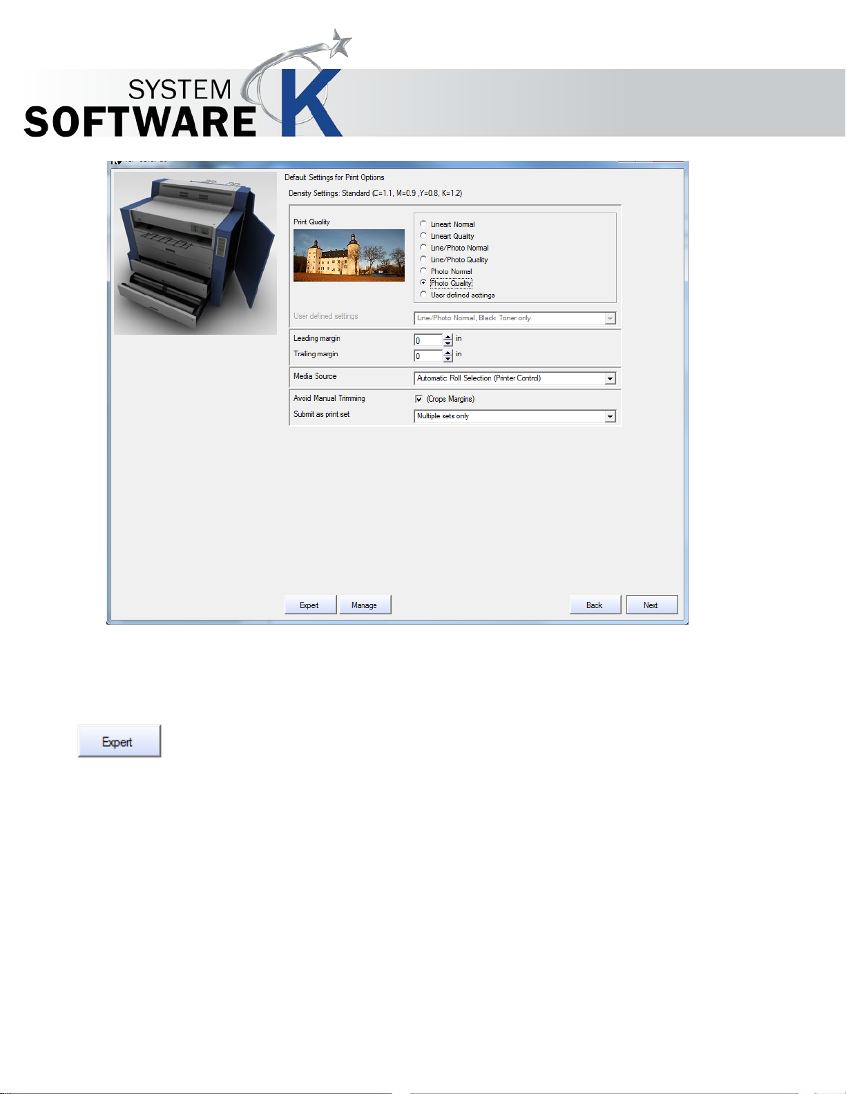
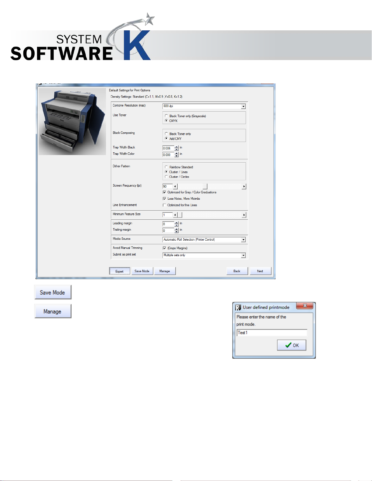
Default Settings for Print Options
These settings are device dependent, especially the Sttings in Expert mode. The following options displayed in the screenshot
base on the options given when configuring a KIP Color 80.
No part of this publication may be copied, reproduced or distributed in any form without express written permission
from KIP. 2015 KIP. v1.
- 19 -
Page 20
KIP Graphics Pro
Please select the print quality you want to use. The line art modes are mainly for CAD drawings, the photo modes mainly for photo
or fine art grphic. From Draft Normal Quality the quality of the output will increase, but the speed decrease.
EADING MARGINS and TRAILING MARGINS, to add additional margins to adjust print placement in length direction.
Use L
Determine the default settings for the connected printer. You can set e.g. the dpi value, as well as trimming and
drying options. Press the E
and settings are device dependent.
XPERT button to open a detailed view of the available print options and settings. The available options
No part of this publication may be copied, reproduced or distributed in any form without express written permission
from KIP. 2015 KIP. v1.
- 20 -
Page 21
KIP Graphics Pro
If you want to save a profile of the print options settings, just click the button S
DEFINED PRINTMO DE
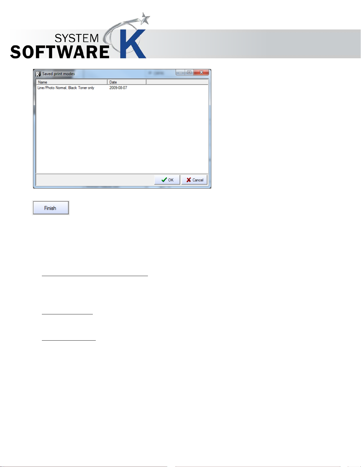
After having created and saved at least one profile, the button
will become available. By clicking it, you may now select a user
defined print options profile displayed within the window S
will appear consequently: enter a user defined print mode profile name. Then click OK.
AVED PRINT MODES.
AVE MODE. The window USER
ANAGE
M
No part of this publication may be copied, reproduced or distributed in any form without express written permission
from KIP. 2015 KIP. v1.
- 21 -
Page 22
Monochrome PDF / PostScript Processing
Minimum line width
Apply transparencies
KIP Graphics Pro
PostScript
(Only for B+W files)
Additional dither modes and parameter setti ng s.
Specify the minimum line width. With 0,00 mm the default within the file will be used.
Check this box to use the settings within the file.
When you have run through all steps of configuration/installation, you finally have to click on F
process. The device should be installed and operational from now on and appears in the window H
within the installed printer list. Before leaving the H
save new and changed device configurations.
ARDWARE window, do not forget to click the button OK, to
INISH to finish the
ARDWARE
No part of this publication may be copied, reproduced or distributed in any form without express written permission
from KIP. 2015 KIP. v1.
- 22 -
Page 23
KIP Graphics Pro
Calibration
You only get to this dialog if you did not found any profiles or refused to search for profiles after the dialog NAME / CONNECTION.
After clicking on F
If you do not wish to calibrate your printer, you have to switch of color management in the later use of KIP Color RIP.client. Not
using color management may cause picture quality losses!
To recalibrate printers that have been already fully installed, you can use this dialog, too. To get there, right-click on an already
installed printer in the window H
Another way to re-calibrate a printer, go to the main window’s menu bar section C
calibration dialog is shown for the printer that is select ed curr ently in the drop dow n list P
main window.
Media calibrations for the RIP mode are created and displayed in the calibration dialog window. Media calibrations apply to the
selected medium and print mode and are a set of color and gray calibrations, ink-limit and gamma settings, length and width
corrections.
INISH in the previous dialog under these conditions, you will be asked for creating a user defined calibration.
ARDWARE and select PRINTER CONFIGURATION CALIBRATION from the context menu.
ONFIGURATION CALIBRATION. The
RINTER within the tab GENERAL of the
The medium displayed in the calibration w indow is that one you set in the window C
As a default, the program only displays recommended print modes.
medium name.
No part of this publication may be copied, reproduced or distributed in any form without express written permission
from KIP. 2015 KIP. v1.
If you want to calibrate further modes, click the button E
When a profile has been successfully applied to the selected print mode, the date of creation appears behind the
- 23 -
XPERT to get the list of all available print modes.
ONFIGURATION / LOADED CONSUMABLES.
Page 24
Profile Library
Spectrophotometer
Calibration Target
Options in the Calibration Dialog
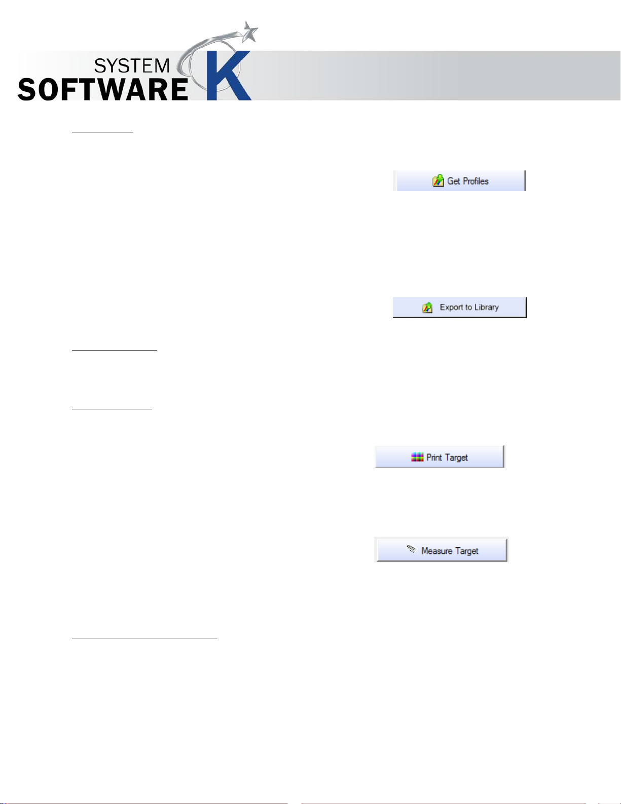
Get Profiles
With this function you can import calibrations that were made on another system.
Open the printer-specific profile library and select the desired filters.
Please consider that the included profile libraries are made for original media from the printer's manufacturer. If you
use different media or feel the quality of the print is not satisfying, please go to § E
proceeding the calibration.
Export to Library
You can save single or all RIP profiles applying to one given printer type.
KIP Graphics Pro
DIT MEDIA PARAMETERS before
Select your device for calibration. We recommend calibration with a spectrophotometer for quality reasons.
Print Target
Check the boxes of the targets you want to print, and click on PRINT TARGET. The
targets will be printed on the printer you have selected. Be sure to have selected the
correct type of target before.
Measure Target
Scan the targets with your spectrophotometer. If you use a
ICColor, the targets will be automatically assigned to their
print modes. That way, there is no definite order for scanning the targets.
Some spectrophotometers may not assign targets to their print modes. In that case, you will be prompted to input the 8 figures
you find on the left at the bottom of the targets.
GretagMacbeth
corresponding
When right-clicking on the quality settings, the following context menu appears
No part of this publication may be copied, reproduced or distributed in any form without express written permission
from KIP. 2015 KIP. v1.
- 24 -
Page 25
Edit media parameters
KIP Graphics Pro
Under certain circumstances, for example when you do not use original media, it may be necessary to change the default
media parameters I
These settings may be necessary for each print mode!
Media parameters should be edited in the order listed below. However, not all steps may be necessary.
1. Define Ink-limit
2. Define Gamma
3. Make grayscale calibration
4. Linearization
1. Ink-limit and Gamma (tab G
Adjust the ink-limit until all gray areas in the lower part are clearly visible. The gray areas should not fade out.
Change the Gamma value until, in the upper part of the print, the brightness of 50% Gray is exactly in the middle of the range
between 100% White and 100% Black.
To check the settings, print a scanner-calibration-target and look at the colors. If the colors fade out, or if you can see color
droplets, please reduce the ink-limit value via E
Then, print a new target and check the colors.
2. No Black Ink (applies only to inkjet printers)
When available, this option allows you to print without black ink. This option is possible for various printer types and media
NK-LIMIT or GAMMA.
ENERAL)
Print a test page via PRINT TEST SHEET.
DIT MEDIA PARAMETERS.
No part of this publication may be copied, reproduced or distributed in any form without express written permission
from KIP. 2015 KIP. v1.
- 25 -
Page 26
KIP Graphics Pro
(e.g. glossy paper) as some ink types do not dry on certain media.
3. Gray Calibration
A gray calibration may help reduce color shifts in gray areas.
To make a gray calibration, proceed as follows:
• Check the box M
• Click P
• Cut out the black & white mask on the left of the target along the trim lines and take the square out of the center.
• With the mask, find the most neutral gray tone within each level and enter the corresponding coordinates in the
• Check the new settings via PRINT TEST SHEET.
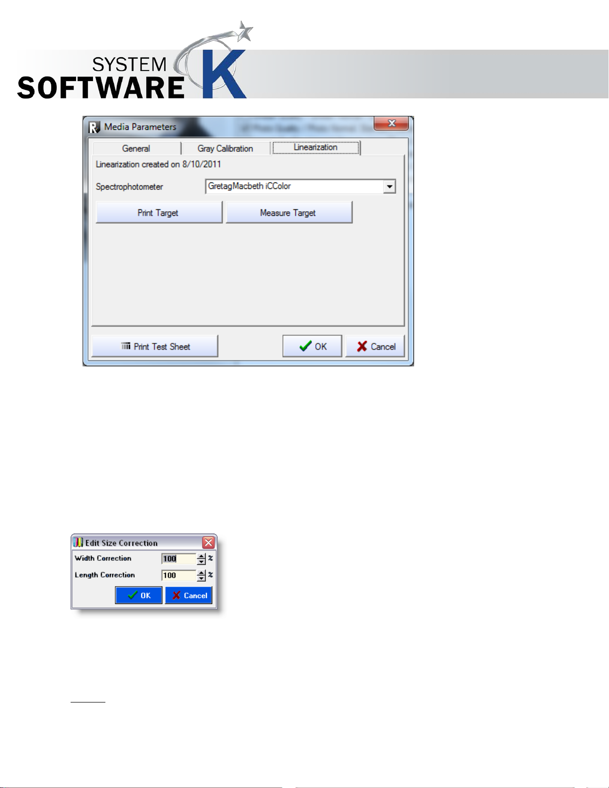
4. Linearization
RINT TARGET to get a calibration target.
window.
ODIFY DEFAULT GRAY VALUE.
Every LED printer has a slightly different curve of printing density. To achieve linear colors you can calibrate KIP Color 80 and
KIP Color 7800 with a spectrometer.
Please select your appropriate spectrometer press Print Target and afterwards start Measure Target.
For a successful linearization the date and time will be displayed.
No part of this publication may be copied, reproduced or distributed in any form without express written permission
from KIP. 2015 KIP. v1.
- 26 -
Page 27
KIP Graphics Pro
Reset media parameters
With this option, the parameters will be reset to the default values.
Delete Size Correction
The saved size correction for the selected print mode will be deleted.
Edit Size Correction
In this case, proceed as follows:
• Set the value for the width and height correction to 100.
• Print the file and calculate the difference between the sizes of original and copy.
• Use the rule of three to calculate the correction factor.
Example
: the original has a height of 120mm; the copy has a height of 126mm.
The correction factor is calculated as follows: 120 / 1.26 = 95.2381
Values between 90 and 110 are applicable.
No part of this publication may be copied, reproduced or distributed in any form without express written permission
from KIP. 2015 KIP. v1.
- 27 -
Page 28

Delete Calibration
The saved calibration for the selected print mode will be deleted.
Use default Calibration
Return to the default calibration delivered with the software.
Import ICC Profile
You may use profiles created without KIP Color Pro spectrophotometer options. Please specify the files here.
KIP Graphics Pro
Measure Target with Spectrophotometer
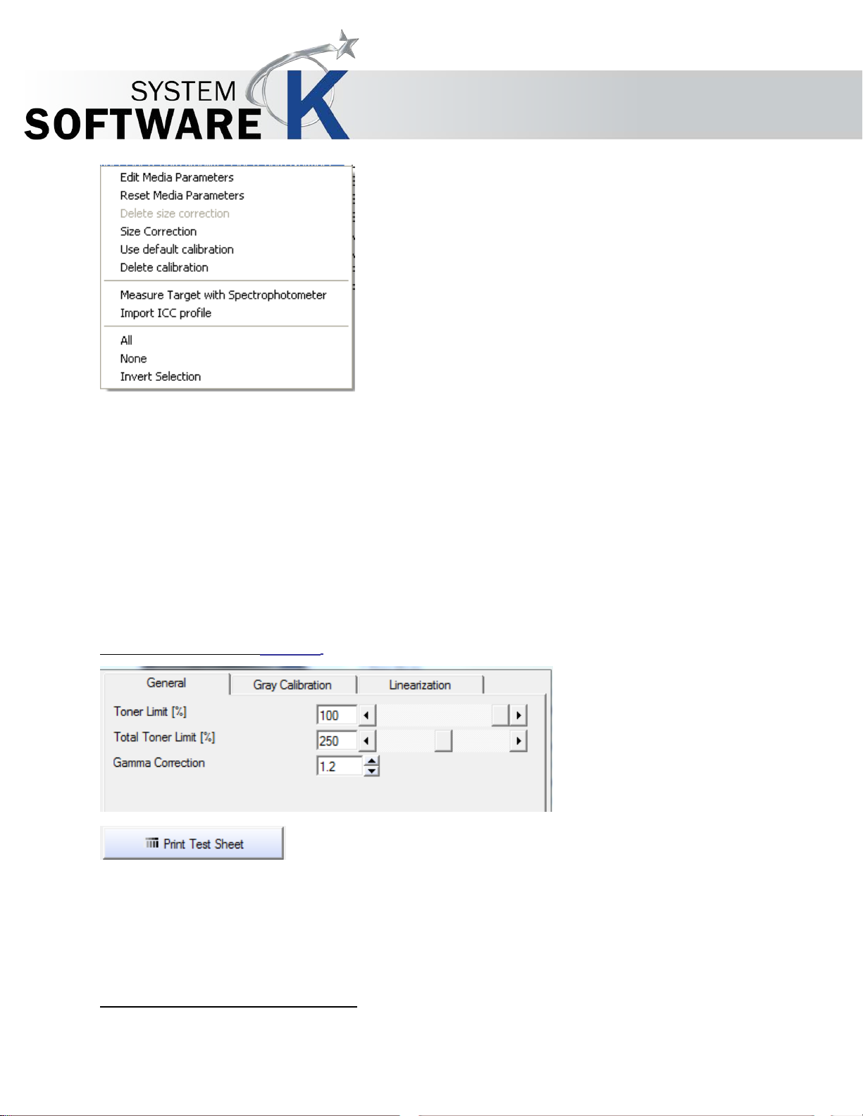
If you can read the target with a spectrophotometer, start the reading process with this option.
Print Mode selection
With AL L, all check boxes will be activated.
ONE, you can deactivate all check boxes with a single click.
With N
With INVERT SELECTION, all active check boxes will be deactivated and vice versa.
No part of this publication may be copied, reproduced or distributed in any form without express written permission
from KIP. 2015 KIP. v1.
- 28 -
Page 29
Printer
Medium
Set Print Size
KIP Graphics Pro
Create Queue
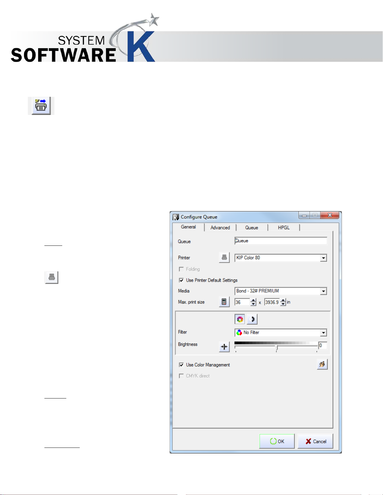
For installing a queue push the CREATE QUEUE button within in the HARDWARE window.
Please note that you first need a fully installed and configured printer on KIP Color RIP before you are able to
create a queue
Queues are prearranged printer configurations. Clients may (or even have to) use these fixed settings which e.g. involve paper and
printing size without having to set them all by themselves. Queues can be configured for each installed printer.
If you had pressed the C
DVANCED, QUEUES and HPGL.
A
Tab General
Queue
First you may rename the queue under QUEUE
enter a specific name.
REATE QUEUE button, the CONFIGURE QUEUE window with four tabs consequently appears: GENERAL,
and
Now select an installed PRINTER that is going
be used for this queue.
If you want to configure your printer first you
have got the opportunity to do so by pressing the
RINTER CONFIGURATION button left of it. A
P
dialog with three tabs appe ars: P
ECHNICAL LABEL and PRINT OPTIONS.
T
RINTER CONFIGURATION button is only
The P
available if the check box
PRINTER DEFAULT SETTINGS is NOT
activated.
For further details regarding to the options
given in this tabs got to § THE CONFIGURATION
WIZARD § PLACEMENT / § TECHNICAL LABEL / §
DEFAULT SET TIN GS FO R PRINT O P TIONS.
You also have to select a MEDIUM used for
queue and its printer. Select one from the drop
down list.
LACEMENT,
OPTION USE
to
this
No part of this publication may be copied, reproduced or distributed in any form without express written permission
from KIP. 2015 KIP. v1.
- 29 -
Page 30
Use Printer Default Settings
Filter and quality settings
KIP Graphics Pro
Next you can set the MAXIMUM PRINT SIZE. Enter manually width and length into the two boxes; or simply leave it to
the system detecting the maximum possible print size with the selected printer/medium by pressing the S
To keep all printer default settings, just activate the USE PRINTER DEFAULT SETTINGS check box option. Under
these circumstances, the button
PRINTER CONFIGURATION explained above is not accessible and the queue will
use all the printer settings set in the printer configuration.
ET SIZE button.
Finally you can set the entire color and filter settings which will take effect on every image sent to the queue.
Most of the options given in there are identical with the options available in the tab GENERAL of the main window. For
further details regarding to those identical functions please go to E
To select and set a customized F
first. For further details, see §
ILTER within the queue configuration window, you have to create one in the FILTER EDITOR
FILTER EDITOR.
DIT PICTURES AND OUTPUT § TAB GENERAL.
No part of this publication may be copied, reproduced or distributed in any form without express written permission
from KIP. 2015 KIP. v1.
- 30 -
Page 31

Copies
Set Output Size
Stamping
Rotation
KIP Graphics Pro
Tab Advanced
In general this tab offers several options to configure the size, number, rotation and similar settings. Most of the options given in
this tab are matching with the tab A
chapter.
For explanations about the rest of the identical functions see of §
DVANCED in the main window. Hence, only the queue specific options are explained in this
EDIT PICTURES AND OUTPUT § TAB OUTPUT OPTIONS.
First enter the desired number of COPIES of the same
Next you can determine the OUTPUT SIZE by
a scale factor from the SCALE BY drop down
You are able to choose among F
EIGHT. The chosen parameter becomes
and H
whilst the other parameters are adapted to the altered
size automatically.
FACTOR will always scale up or down with a fixed
W
IDTH will scale to a fixed width
HEIGHT will scale to a fixed height.
IT TO SHEET will make the SET SIZE button
F
By activating it you may now choose among different
predefined sizes or opt for using the maximum print size that
is possible with your printer/medium and its settings.
Adding a stamp onto the image will create a diagonal text entry
on the image. If you checkmark the option, further option will
become available:
ACTOR, WIDTH
document.
selecting
menu.
alterable
factor
available.
Stamp text
Enter the text that is going to be used as a stamp.
Stamp size
Enter the size of the text entry.
Being different from the same option in the main window, ROTATION given in the queue configuration lacks of the option to set
an AUTOMATIC (PAPER SAVE) mode. All other rotation degrees are available.
No part of this publication may be copied, reproduced or distributed in any form without express written permission
from KIP. 2015 KIP. v1.
- 31 -
Page 32

Queue description
Priority
De-/Activation of the Queue
Set Time Frame for Queue Activity
Listen to LPR
Tab Queues
KIP Graphics Pro
In this tab you can first type in a personal QUEUE DESCRIPTION. The description will appear as a pop up info box when
placing the mouse cursor on the print device’s name displayed in the main window’s tab G
You can then set a PRIORITY for the queue. NORMAL means that the print jobs send to this queue will be processed in
normal order. HIGH sets priority to a preferred level, whilst LOW sets a subordinate status. These low priority jobs do not start
processing unless higher rated jobs are finished.
Further you can manually activate/deactivate the queue. Simply check the box at ACTIVE to activate the queue. As default, it
is already active.
You can then define a range of time when the Queue will be active by checking the box at ONLY ACTIVE FROM. Now enter
the desired time frame.
ENERAL.
If you want to use a LPR connection, activate this option and type the queue name into the text field.
No part of this publication may be copied, reproduced or distributed in any form without express written permission
from KIP. 2015 KIP. v1.
- 32 -
Page 33

Listen to raw port
If you want to use a TCP/IP port input instead, just type in the correct port number you want to use.
Tab HPGL
KIP Graphics Pro
To determine how to manage HPGL-image files that are sent to this queue, use this tab.
For a detailed explanation of the functions and options given in this tab, see
The HPGL-queue configuration only lacks of the option C
When you are done, press OK in order so save and quit the queue configuration. The configured queue is now recognizable like a
printer in the HARDWARE window under INSTALLED PRINTERS indicated with a QU . Do not forget to press OK in the HARDWARE
window to save the new or changed devices.
§ EDIT PICTURES AND OUTPUT TAB HPGL.
OPIES; all other options are identically.
No part of this publication may be copied, reproduced or distributed in any form without express written permission
from KIP. 2015 KIP. v1.
- 33 -
Page 34

KIP Graphics Pro
Menu Bar Options
This chapter contains an overview about all the functions given in the menu bar. By using the menu bar, you can open most of the
KIP Color RIP.clients’ main applications and a lot of additional options. Some options may be inaccessible depending on you are
using the explorer main window or the preview main window of KIP Color RIP.
File
By opening FILE given in the menu bar section you may RESET the KIP Color RIP.client program – e.g. in order to update printer
settings or file selections – or EXIT the program.
Configuration
In general, you can configure all hardware and KIP Track settings by selecting this menu bar section.
No part of this publication may be copied, reproduced or distributed in any form without express written permission
from KIP. 2015 KIP. v1.
- 34 -
Page 35

KIP Graphics Pro
Hardware
This option will take you to the window HARDWARE as explained in § HARDWARE CONFIGURATION. New printers as well as queues
can be added and existing hardware installations can be altered.
Calibration
This is another alternative to reach the calibration dialog which is explained more detailed in § CALIBRATION within the § THE
CONFIGURATION WIZARD. After activating this command, you will directly be guided to the calibration dialog of the print device that is
at this time selected as P
RINTER within the tab GENERAL of the main window.
Pause Unattend / Resume Unattend
Pause or resume the unattend on the KIP Color Controller your client is connected to.
Preferences
Selecting this menu bar option will take you to the PREFERNCES dialog. The options given in this window are important further hardware settings. To learn more about the
To get to the window PREFERNCES, click CONFIGURATION in the menu bar, then
REFERNCES. The dialog contains two tabs: GENERAL and EXPLORER WINDOW.
P
REFERNCES-dialogs offer important additional hardware- and file settings.
The P
No part of this publication may be copied, reproduced or distributed in any form without express written permission
from KIP. 2015 KIP. v1.
- 35 -
Page 36

Create user-defined formats
Tab General
Paper Format
You can choose a standard ISO or US format or define your own formats.
ISO – DIN formats are selected as standard formats.
US – US formats are selected as standard.
USER DEFINED – customized formats will be applied.
1. In the drop down list under PAPER FORMAT, select USER DEFINED
and click on EDIT PAPER SIZES. 2. A dialog opens in which
adjust user-defined formats and select ISO and/or US formats additionally.
KIP Graphics Pro
you can
Unit
Select MILLIMETER or INCH from the drop down list.
Simple filter editor by Default for RIP
If this check box is checked, the filter editor will be displayed in the simple mode.
Learn more about the filter editor by referring to §
FILTER EDITOR
No part of this publication may be copied, reproduced or distributed in any form without express written permission
from KIP. 2015 KIP. v1.
- 36 -
Page 37

KIP Graphics Pro
Use Screen ICC Profile
If you want to use the ICC profile of the operating system for your screen, check the corresponding box.
Show warning for demo version
Check this box to activate the warning message window which shows up every time you start KIP Color RIP wi thout a lice nsed
dongle. You also can deactivate this message in the message window itself. Go to the main chapter § KEYCODE ENTRY for
further instructions.
Show warning when configuration changes
By activating this box a warning window will appear after various configuration changes.
Show warning when unsaved changes will be deleted
A warning message will appear if altered configurations are deleted.
Start new job after submit
Activate this option in order to automatically delete the job list after submitting. If you want to be asked first before deleting,
activate the lower A
SK ON JOB SUBMIT.
Job number in printer display
By selecting this option, the job number of the current print job is displayed at the printer’s display if available.
No part of this publication may be copied, reproduced or distributed in any form without express written permission
from KIP. 2015 KIP. v1.
- 37 -
Page 38

KIP Graphics Pro
Use compressed transfer
If you have a slow data connection, the option USE COMPRESSED TRANSFER is worth activating. Please bear in mind that
decompressing data will result in a higher system workload.
Tab Explorer Window
To determine which types of files will not be listed and appear in the system
RIP.client start up main window, use the A
subsequently.
Type in the correct system file description name (e.g.: *.pdf) to hide these files while using the explorer search window of KIP Color
RIP.client.
If you want to uncover previously hidden files, highlight a file type in the HIDDEN FILES list, then press the DELETE FILE
NAME bin-button.
DD FILE NAME button. The ADD FILE NAME window will appear
explorer window provided by the KIP Color
No part of this publication may be copied, reproduced or distributed in any form without express written permission
from KIP. 2015 KIP. v1.
- 38 -
Page 39

KIP Graphics Pro
features, see § FURTHER HARDWARE SETTINGS: PREFERNCES.
Show Filters
By using the FILTER EDITOR in order to work with and improve picture quality, you may create customized filter, which can be
saved on your system. To get an overview about all your customized and pre-arranged filters on your system, go to the FILTER
ARCHIVE window by using the menu bar option of the same name.
Change the appearance of the files within this window by using the buttons at the top right hand side of the
window.
Right-click on a filter representation and select among three options: R
To apply a highlighted filter to the currently selected image within the main window, hit the USE FILTER
button, which will become accessible after highlighting a filter icon. The filter name will now appear as the selected filter within the
ENERAL of the main window and the effects of the filter will be applied to the selected files.
tab G
To learn more about the F
ILTER EDITOR in general, go to § FILTER EDITOR.
ENAME or DELETE or USE FILTER.
Log in …
The window LOGIN, which appears after selecting the menu bar option, is exactly the same as seen with the first start (see § KIP
COLOR RIP.CLIENT LOGIN). You may now connect to another KIP Color RIP.server, while KIP Color RIP.client is still running.
No part of this publication may be copied, reproduced or distributed in any form without express written permission
from KIP. 2015 KIP. v1.
- 39 -
Page 40

KIP Graphics Pro
View
Refer to this tab to obtain various display configurations. These options will affect the way of representation of files within the explorer
list and are therefore not available when using the preview (image setting) window.
Large Icons
Alter the appearance of files within the explorer list to large icons.
Small Icons
Selecting this option will change the appearance of files within the explorer window to small icons.
List
Change the way of the file arrangement to a list arrangement.
Details
This option will expand the LIST display method explained above with additional information about the files.
Show button caption
If deactivated, the toolbar (below the menu bar) is not subtitled. To learn more about these icons and tools, go to § KIP COLOR
RIP.CLIENT MAIN APPLICATIONS § SELECTING FILES.
Thumbnails
You may determine if little preview images (called thumbnails) at the left of each file within the explorer list are displayed. Select
G
ENERATE ALWAYS to let them appear always as possible. Select GENERATE ONLY ON WRITEABLE DEVICES to determine
the appearances of thumbnails only on writeable devices. Finally, select GENERATE NEVER to switch off thumbnails within the
explorer screen of the KIP Color RIP.client main window.
Preview
This opens the PREVIEW of the highlighted file. For a detailed explanation of the Preview, go to § PREVIEW.
Refresh
This option provides a manual way to start a refreshing KIP Color RIP.client. In the most cases this will not be necessary because
No part of this publication may be copied, reproduced or distributed in any form without express written permission
from KIP. 2015 KIP. v1.
- 40 -
Page 41

KIP Graphics Pro
KIP Color RIP.client automatically refreshes after various settings.
A useful opportunity to use R
on your local or other available systems. This may be not the case if files in use have been changed its system location, so these
files will disappear from the explorer list.
Edit
This menu bar section offers to manage selection of files in the job list. It is only available in the explorer main window. At least one
file has to highlighted to get access to the edit options.
Select all
All files within the location/folder as seen in the middle part of the main window are
highlighted. Note: if the selections include non-printable files, you will receive a message,
informing you about the fact that the file failed to be imported to KIP Color RIP
successfully. You may try to convert these files into a compatible format. Nevertheless,
these non-printable files are selected like any other file within the selection.
EFRESH may be e.g. to check, if KIP Color RIP is still able to find the selected files of the explorer list
Select none
No file is highlighted. Previous selections are canc elled.
Invert Selection
To switch selected files to non-activated and vice versa use this command.
Actions
When opening the A
single file by clicking on V
window by clicking Job Editor. Both options mentioned here are also available in the tool bar of the
main window.
For detailed explanations see § VIEWER/EDITOR and § JOB EDITOR.
You also may R
system location, size, etc.
CTION-section, you get access to the VIEWER/EDITOR window for a
IEWER/EDITOR. Additionally, you may open THE JOB EDITOR
EDO a FILE CHECK in order to check and update if highlighted files have
current
altered in
Info
In general this option is everything you need to obtain information about your system, print jobs and KIP Color RIP.
No part of this publication may be copied, reproduced or distributed in any form without express written permission
from KIP. 2015 KIP. v1.
- 41 -
Page 42

KIP Graphics Pro
About
In this window you can have a look at everything necessary considering your KIP Color
RIP.client version.
Job Monitor
This opens the KIP Color RIP.monitor. This service is an important hel pful too l of KIP
Color RIP, which makes it possible to watch and control submitted print jobs.
To learn more about the essential KIP Color RIP.monitor go to §
Upload Local Filters to KIP
If there are new and customized filter edits, use this command to upload them to the filter archive of your network. They are now
available for all clients of your KIP Color RIP network.
KIP COLOR RIP. MONITOR.
Help
By using this option you can switch to the KIP Color RIP.client online help. Select the chapter of interest and double click to open
the subchapters. Use the icon bar at the top to activate further options.
No part of this publication may be copied, reproduced or distributed in any form without express written permission
from KIP. 2015 KIP. v1.
- 42 -
Page 43

KIP Color RIP.client main applications
Selecting Files and further basics:
Every time you start KIP Color RIP.client you will start with the explorer window:
KIP Graphics Pro
Search and select a system location (folder) of your system at the left. Selected files will appear in the middle part of the center
section of the window. (Please note that the context menu opened with a right-click on an explorer and file window entry will open the
standard context menu of your operating systems regarding to the selected file.)
Then select one or multiple printable file within the middle part of the window: The right part of the window, which is the actual image
configuration window, becomes now accessible. To navigate through your system location, you may also use the buttons B
ORWARD and UPWARD of the tool bar below the menu bar.
F
To change the representation of files within the central files display section, use the button VIEW of the tool bar. The
options L
explained in
To open the V
the tool bar as well. The VIEWER/EDITOR is a helpful tool in order to rearrange a picture in view of general arrangements,
e.g. changing the rotation or cut out parts of the picture. If you save any alterations of the image within the V
window, these alterations will be applied to the original file.
To open the J
print device or explode multipage files. See §
After selecting a printable file, the tab area at the right becomes available. All the options given in there are important to configure and
set your image/output.
No part of this publication may be copied, reproduced or distributed in any form without express written permission
from KIP. 2015 KIP. v1.
ARGE ICONS, SMALL ICONS, LIST and DETAILS given in there are identical with some of the options as
§ MENU BAR OPTIONS
IEWER/EDITOR window for the currently highlighted file, use the VIEWER/EDITOR button located within
OB EDITOR window use this button. Here you can line up multiple files and send them simultaneously to the
§ VIEW.
JOB EDITOR to learn more about this helpful tool.
- 43 -
ACK,
IEW/EDIT
Page 44

Remove white borders
Original Size
Copy Size
Copies
Factor
Fit to Sheet
Tab General
If the image files contain white borders, simply activate this
option to remove them from the print out. By removing white
borders, more media space is freed up and thus more images
may fit on one print out media.
The size of the original (width and height) is shown under
O
RIGINAL SIZE.
KIP Graphics Pro
The Print Size can be different from the original size.
By default, the original size entered is taken as the
output size. The output size can be increased or
reduced by a percentage. You may of course enter
the desired copy size directly in millimeter or inch. The copy
width or length always changes proportionally when you
alter one of these parameters.
ET SIZE button opens a menu, where
The S
can pick a predefined size or decide to print with
M
AXIMUM PRINT SIZE depending on the size
medium in use.
Hint: With th e key combination Ctrl and Page-up, the
maximum print width will be displayed.
Enter the number of copies required under COPIES. If
copy is supposed to be done first, set the number of copies to "1".
The option J
defines the number of repetitions of the same job, whilst C
to the information under the N
OB COUNT given below the tab area is not to be confused with the number of COPIES, since JOB COUNT
OPIES sets the number of the selected document. Just pay attention
O. column in the job list after altering the JOB COUNT or COPIES parameters.
you
of the
a test
Scaling / Position
Here you can define the scaling type of your print.
With factor the given scale factor is used. If the print does not fit on the media, the width will turn to red and you are not able to
submit the print until you change it.
No part of this publication may be copied, reproduced or distributed in any form without express written permission
from KIP. 2015 KIP. v1.
- 44 -
Page 45

Place on Sheet
Printer
Medium
Print Mode
Filter
KIP Graphics Pro
The image will be increased or decreased. Either width or height will fit to media size and the opposite value will be smaller
than the media size. With the position field you can decide where the origin is placed to start the calculation. The scaling factor
is calculated automatically.
Here you can define the scale factor yourself. The result will be placed on the chosen position. If the media is bigger, you will
have white area around. If the media size is smaller, the print will be clipped.
Select the desired output device from the drop down list which contains all installed printers and queues.
The button next to the printer list opens the window for the printer/queue configuration. The dialog for the printer
configuration is device-dependent:
In the tab P
arrangements of the picture. In the tab C
mandatory, KIP Color RIP will open the dialog during job submission.
RINT OPTIONS you can change the settings of your printer. In the tab PLACEMENT you set additional
OST TRACKING you may enter information for KIP Track. If values are
A selection of different media is displayed under MEDIUM. Select the paper type you want to use for your output.
All calibrated paper types are displayed with black letters, whereas the paper types with red fonts have not been calibrated yet
or are not available for the selected printer. A description of the problem is shown when pointing to the medium name.
You will only be able to start the output if you have selected a calibrated paper type.
The list of media can individually be set and calibrated for every printer by clicking on the configuration button left of
the media drop down list. It will take you to the C
ONFIGURATION / LOADED CONSUMABLES as known from THE
CONFIGURATION WIZARD. There is again the possibility to EDIT MEDIA by using the corresponding button which takes
you to the D
EFINE MEDIA dialog.
Select the print mode. You may choose color or gr ay scale / b/w mode.
The availability of selections is file and device dependent.
Select the corresponding color mode. You may choose color, gray scale or b/w mode. The a v ailab ility o f sele ctio n s is file
dependent.
You can then select a F
that were saved in the filter archive are displayed in the drop-dow n list under F
The Filter *N
The filter *C
O FILTER* means no filter is in effect.
URRENT* is a temporary filter with the settings made in the FILTER EDITOR which have not been saved yet.
ILTER from the drop down menu. Filters are procedures to alter the visual shape of an image. All filters
ILTER and can be selected from there.
No part of this publication may be copied, reproduced or distributed in any form without express written permission
from KIP. 2015 KIP. v1.
- 45 -
Page 46

Brightness
Use Color Management
KIP Graphics Pro
You will get to the filter editor with the menu fields CHANGE and NEW below the drop down list. Using them you will be able to
set a personalized FILTER.
You may save a current or new filter on your system if you push the S
ILTER EDITOR. Enter a filter name which will be at your disposal in the FILTER drop down list further on.
the F
AVE button. It becomes achievable after any changes in
Further details referring to creating, changing and saving filters are described in the §
You may alter the brightness of a copy with the brightness slider. When using normal originals, we recommend setting the
value of the slider to 0. Moving the slider to the left (negative values) will result in a copy darker than the original, whereas
moving the slider to the right (positive values) will make a brighter copy. Clicking on the button R
original position.
If you want to work with the color management, check the box USE COLOR MANAGEMENT. Click on the speed button
in the same field to open the C
OLOR MANAGEMENT OPTIONS window .
FILTER EDITOR.
ESET will reset the slider to its
No part of this publication may be copied, reproduced or distributed in any form without express written permission
from KIP. 2015 KIP. v1.
- 46 -
Page 47

KIP Graphics Pro
You may select profiles for RGB and CMYK. Embedded Profiles are used by default (check box USE EMBEDD ED
PROFILES). If no profiles are embedded in the file, the option from the dropdown menu is used. If you prefer a special profile
instead of the standard ones you can select ICM file and specify the path in the box below.
Rendering Intent
Often, device gamuts will not be large enough to reproduce the desired color appearances communicated by the PCS
values. Four rendering intents (gamut mapping styles) are provided to address this problem. Each one represents a different
compromise. The colorimetric rendering intents operate on measurement-based colorimetric values... The other rendering
intents operate on colorimetric values which are corrected in an as-needed fashion to account for any differences between
devices, media, and viewing condition s.
ERCEPTUAL
P
The exact gamut mapping of the perceptual intent is vendor specific and involves compromises such as trading off
preservation of contrast in order to preserve detail throughout the tonal range. It is useful for general reproduction of images,
particularly pictorial or photographic-type images.
ELATIVE (Colorimetric Intent)
R
This intent re-scales the in-gamut, tristimulus values such that the white point of the current medium is mapped to the PCS
white point (for either input or output). It is useful for colors that have already been mapped to a medium with a smaller
gamut than the reference medium (and therefore need no further compression).
ATURATION
S
This intent sets brighter colors by neglecting the color fidelity.
BSOLUTE (Colorimetric Intent)
A
For this intent, the tristimulus values of the in-gamut colors are unchanged. It is useful for spot colors and when simulating
one medium on another (proofing).
No part of this publication may be copied, reproduced or distributed in any form without express written permission
from KIP. 2015 KIP. v1.
- 47 -
Page 48

CMYK direkt
Margins
Mirroring
Rotate
With Color Management off you can use CMYK direct. For CMYK files the values will be directly given to the printer.
Tab Output Options
KIP Graphics Pro
You can set additional white margins, whose size can individually be set for the left, right, top and bottom. Bear in mind that the
maximum print width of the initial copy decreases by the size of the margins.
If you want a continuous white margin of e. g. 20 mm, just activate B
rest of the margins are adjusted automatically.
Check the box MIRRORING if you need a mirror image of the copy.
If you want the output to be rotated without paper-save function, select a rotation degree. The selection adds to the settings set
with T
HE CONFIGURATION WIZARD PLACEMENT.
No part of this publication may be copied, reproduced or distributed in any form without express written permission
from KIP. 2015 KIP. v1.
- 48 -
ORDERS EQUAL and set the left margin to 20 mm. The
Page 49

Label
Panel Size (Width/Height)
KIP Graphics Pro
Additional information can be entered for the label (e.g. customer, employee). You have the possibility to use the history for
frequently used label entries.
Please consider that the label edit explained here doe s not change label settings that are available in the P
of THE CONFIGURATION WIZARD; but it will extend the standard label with the additional, customized information.
Tab Paneling
For large format outputs, such as posters or presentations for fairs and exhibitions, it is necessary to divide the copy into several
different panels. As soon as the required output size exceeds the maximum print width or the maximum print length of a printer,
certain settings become necessary under PANELING.
LACEMENT dialog
You can choose to print panels in the width, in the height, or both.
To do so, check the box(es) W
GIVEN or COUNT GIVEN radio button.
If you have activated the automatic length recognition when scanning, a paneling with respect to height is not
possible.
No part of this publication may be copied, reproduced or distributed in any form without express written permission
from KIP. 2015 KIP. v1.
IDTH and/or HEIGHT. Enter then either a fixed size or a number of panels by selecting the SIZE
- 49 -
Page 50

Calculate (Panel Sizes)
Paneling is designed for easy use: KIP Color RIP.client calculates the number and maximum size of the panels that will fit on
the paper width, including the overlap (if selected).
Simply click C
The maximum print width of the selected printer is then entered under S
under C
If you change the output size or the output device in the main window, you must click on the button C
recalculate the size and number of panels. The values are then immediately updated. Of course, you may change the
suggested values manually.
Example:
The poster you want to print is supposed to be 4000 mm wide but the maximum output width of the printer is
900 mm.
* If you enter "900 mm" under S
* If you enter "5" under C
OUNT GIVEN.
KIP Graphics Pro
ALCULATE.
IZE GIVEN, while the number of panels is displayed
ALCULATE once again to
IZE GIVEN (width), four 900 mm wide panels and a 400 mm wide one will be printed.
OUNT GIVEN, five 800 mm wide panels will be printed.
Select Panels for the Output
If you choose to print an image with panels, you will see their distribution, including the overlap, in the preview after activating
the tab P
The preview of the panels is also possible in combination with the area of interest (AOI) (see §
ANELING.
PREVIEW § SELECT AN AREA).
You have the option to print single panels. Each panel is displayed with a magenta-colored border. To activate or deactivate
No part of this publication may be copied, reproduced or distributed in any form without express written permission
from KIP. 2015 KIP. v1.
- 50 -
Page 51

Advanced Paneling
Glueing Marks
Origin
KIP Graphics Pro
the panels just click on the desired panels.
Right-clicking on the Panel Preview image opens a context menu which provides other ways to select panels for printing:
ALL PANELS – activates all panels.
NO PANELS – deactivates all panels.
INVERT SELECTION – turns activated panels into deactivated and vice versa.
Overlap / Glueborder
You can print with overlaps or glueborders. Overlaps are filled with the image where as the glueborder will add white areas.
Note: If you set the maximal print width of the printer under SIZE GIVEN, it is reduced by the selected overlap.
For further customizing please tick ADVANCED PANELING and click CHANGE. Here you can change the size of each panel
individually.
If you check the box GLUEING MARKS, a mark will be set at the beginning of the overlap.
Define the first panel. The image will be printed row by row.
No part of this publication may be copied, reproduced or distributed in any form without express written permission
from KIP. 2015 KIP. v1.
- 51 -
Page 52

KIP Graphics Pro
Tab HPGL
If you are working with HPGL files (vector files), the tab HPGL will be available in the main window. With these files, the
emulation of some printers is possible.
Pen Settings
HPGL/2 files are able to store certain parameters within the file. The usage of this information can be switched on and off.
PAPER SIZE – If this option is active the image dimensions are read from the file. If you deactivate this option the imag e
dimensions is calculated by the software. Huge white areas outside of the image will not be printed.
PEN
WIDTHS – Deactivate this option in order to set the size of the pens manually.
PEN
COLORS - Deactivate this option in order to set the pens colors manually .
MERGECONTROL – Controls the merging of different layers. This command works like the menu on most HP printer displays.
If parts of an HPGL are not displayed correctly you can switch this option OFF/ON.
COPIES – Determines if the value for the number of copies is read from the file. If the option is checked, you cannot set the
number of copies in the main window’s tab GENERAL.
User Pen Settings
Under U
the file. If you are working with a HPGL file (not HPGL/2), you have to coordinate the pen width and the pen color. These files can
only be edited when the menu fields U
THE FILE are not activated. The user-defined pen parameters can be saved and loaded via the icons in the lower part of the
HPGL window.
SER PEN SETTINGS, you can alter the line thickness and RGB colors of pens and overwrite the values determined from
SE PEN WIDTH AS DEFINE D IN THE FILE and USE PEN COLORS AS DEFINED IN
No part of this publication may be copied, reproduced or distributed in any form without express written permission
from KIP. 2015 KIP. v1.
- 52 -
Page 53

KIP Graphics Pro
Change Pen Color
To change color values, click on the box to the right of the RGB value of the corresponding pen. The window EDIT COLORS
appears on the screen.
Select one of the 48 basic colors.
Confirm with OK.
The selected color is assigned to the corresponding pen.
Repeat this process for each color.
With the menu field D
pen as user-defined colors.
Save / Load Pen Parameters
You have the option to save the altered pen parameters of a file for later applications using the icon S
parameters are then stored under a filename (e.g. customer, employee or project) that gets the addition "PEN". Using the
icon L
EFINE CUSTOM COLORS, you can define more color tones and save or assign them to the corresponding
AVE. The
OAD, the parameter file can be reloaded at any time.
Preview
If you click on the button PREVIEW, you will get to the preview window for HPGL files. The HPGL file will be displayed with the
current settings (line thickness, colors, rotate file etc.).
If you want to check details of the drawing, you have the option to enlarge sections. To do this, draw a rectangle with the left
mouse button and click on the button ZOOM IN . This can be repeated several times.
With the button Z
With the cursor keys to the right of the button Z
left, up or down. With the rhombus, the complete picture (full picture) is recovered.
The status line in the lower part of the window shows the size of the window as well as the size of the drawing.
To get a preview of the possible print out, use the button P
the PREVIEW by opening the menu bar options VIEW
order to open a preview. To leave the P
To learn more about the P
Buttons:
OOM OUT, the drawing can progressively be reduced again.
OOM OUT you can move the enlargement half the size of the section to the right,
REVIEW at the bottom part of the tab area. You may also open
PREVIEW. Please note that an image file has to be highlighted in
REVIEW screen, once again press the PREVIEW button.
REVIEW feature, please continue reading at § PREVIEW.
SAVE / LOAD PRESET Your current selection of the different settings can be saved for further reuse wit htese
If one or multiple files have been selected you may start printing by using the large P
bottom’s right hand side corner. If no file is selected or problems with hardware or media configurations
occurred, the button will appear red. By pointing at the red button with the mouse cursor, a little information
bubble will appear which informs about the cause of the problem. Also pay attention to red entries in the tab
area indicating corrupted or incomplete hardware settings/installations (there are roll over information for
this entries, too).
RINT button at the
No part of this publication may be copied, reproduced or distributed in any form without express written permission
from KIP. 2015 KIP. v1.
- 53 -
Page 54

KIP Graphics Pro
Viewer/Editor
The Viewer/Editor is activated by selecting the option from the menu bar ACTIONS VIEWER/EDITOR or by using the
VIEWER/EDITOR button from the tool bar. You have to highlight one file of the job list to start the VIEWER window.
The Viewer can be used to view image files. Image files may be altered in general settings. You are e.g. able to mirror,
rotate and invert the image or add additional colors, text or erase parts of the picture. It is even possible to apply filter edits to the
image within the VIEW/EDIT window (to learn more about the FILTER EDITOR refer to § FILTER EDITOR). Please note: if you
save any of these altered settings, you may save this new image file on your system or just override the old file.
It is only possible to run one Viewer/Editor on one system at present time. If you want to view another document, you first have to
close the current viewer. To leave the V
IEWER/EDITOR just close the window
The V
IEW/EDIT window’s upper boundary presents specifications of the file in focus regarding to file-name, type and color mode (e.
g. RGB).
There are these following options represented by symbols at the upper tool bar of the V
No part of this publication may be copied, reproduced or distributed in any form without express written permission
from KIP. 2015 KIP. v1.
- 54 -
IEWER:
Page 55

Load File
You may open another file by pushing the folder button.
Save File
In order to save altered image setting, use the button SAVE FILE. You may override the old file version or create a new one
by allocating another file name.
KIP Graphics Pro
Print Image
PRINT IMAGE opens a window with the tabs GENERAL, ADVANCED and PANELING. Make settings as usual.
Undo Last Action (Ctrl +Z)
If the image has changed in some way, you may undo the last step to recapture the previous condition.
Show/Hide Spy Window
This opens a little window which shows the area pointed to. The zoom size (see above) chosen in the Viewer has no effect on
the representation size in the spy window.
No part of this publication may be copied, reproduced or distributed in any form without express written permission
from KIP. 2015 KIP. v1.
- 55 -
Page 56

KIP Graphics Pro
Zoom Options
Further you can locate buttons under ZOOM OPTIONS to ZOOM IN or to ZOOM OUT the picture.
Alternatively, press the left mouse button while pointing to the image in order to zoom in or use the right mouse button for
zooming out the image.
You get informed about the current zoom factor and resolution by paying attention to the figures given at the bottom of the Viewer
window.
OOM TO 1:1 takes you back to the original size. It is neither possible to set a scale lower than 1:1 nor there is a higher scale
Z
than 16:1.
Zoom to Window Size
If it is bigger than one window, an image is zoomed to a size fitting into one window by pressing the extra
TO
WINDOW SIZE button. Now you do not have to scroll in order to
view the whole picture.
Scale Image
You may alter the size (scale) of the image by clicking the
SCALE IMAGE button. The SCALE IMAGE
appear.
At top part of the window the original S
RESOLUTION is displayed.
You may now alter the size in the second part of the window,
named N
RESOLUTION and SCALING. If the checkbox Keep
activated, all factors are automatically altered harmonizing
the manual altered factor.
EW SIZES. You may alter the parameters SIZE,
IZE and
window will
Proportions is
ZOOM
Finally, the drop down menu SCALING METHOD offers different in detail scaling methods.
No part of this publication may be copied, reproduced or distributed in any form without express written permission
from KIP. 2015 KIP. v1.
- 56 -
Page 57

Horizontal Mirror
Press this button to mirror the image in horizontal dire ctio n.
Vertical Mirror
Press this button to mirror the image in vertical direction .
KIP Graphics Pro
Rotate by 90° ccw
Rotate the image by selecting three different rotation possibilities (ROTATE BY 90°COUNTER-CLOCKWISE, ROTATE
180°, ROTATE BY 90° CLOCKWISE).
BY
Invert Image
Invert the image colors and contrast by using this button.
No part of this publication may be copied, reproduced or distributed in any form without express written permission
from KIP. 2015 KIP. v1.
- 57 -
Page 58

Change Color Mode
Despeckle
KIP Graphics Pro
If you want to despeckle the image and the option is
accessible, press this button. It is only accessible if you work
with Black & White images. If you want to configure despeckle
parameters, click on the little triangle at the right of the symbol. A
drop down menu appears: click the single entry
ESPECKLE in order to open the window
D
DESPECKLE PARAMETERS.
The options are identical with the options given in the F
of the option I
NVERTED (within the VIEW/EDIT window you may invert the contrast by simply clicking on the button
INVERT IMAGE located in the tool bar and explained above).
To learn more about the despeckle routines, refer to §
WHITE MODE).
ILTER EDITOR’s tab POSTPROCESSING except of the omission
FILTER EDITOR TAB POSTPROCESSING (BLACK &
You can change the color space of the selected file into RGB, Lab, or CMYK. To do this, use the following options:
S
OURCE:
SE EMBEDDED PROFILE – the ICC profile of the file will be used
U
ELECT PR OFILE – according to the selected file, a standard sRGB or CMYK profile will be used. This option allows
S
you to select an external ICC (ICM) profile
R
ENDERING INTENT
In general, actual device gamuts will not be large enough to reproduce the desired color appearances communicated
by the PCS values. Four rendering intents (gamut mapping styles) are provided to address this problem. Each one
represents a different compromise. The colorimetric rendering intents operate on measurement-based colorimetric
values... The other rendering intents operate on colorimetric values which are corrected in an as-needed fashion to
account for any differences between devices, media, and viewing conditions.
ERCEPTUAL
P
The exact gamut mapping of the perceptual intent is vendor specific and involves compromises such as trading off
preservation of contrast in order to preserve detail throughout the tonal range. It is useful for general reproduction of
images, particularly pictorial or photographic-type images.
ELATIVE (Colormetric Intent)
R
This intent re-scales the in-gamut, tristimulus values such that the white point of the actual medium is mapped to the
PCS white point (for either input or output). It is useful for colors that have already been mapped to a medium with a
smaller gamut than the reference medium (and therefore need no further compression).
ATURATION
S
This intent sets brighter colors by neglecting the color fidelity.
A
BSOLUTE (Colormetric Intent)
No part of this publication may be copied, reproduced or distributed in any form without express written permission
from KIP. 2015 KIP. v1.
- 58 -
Page 59

Filter
KIP Graphics Pro
For this intent, the tristimulus values of the in-gamut colors are unchanged. It is useful for spot colors and when
simulating one medium on another (proofing).
TARGET: Select the target color space and, if need be, the corresponding ICC profile.
Open the filter editor to change the image.
Switch to Zoom Mode
Just press the button SWITCH TO ZOOM MODE in order to leave another currently activated image setting (e.g. 2-POINT
DESKEW) and to switch back to standard zoom screen represented by the cursor.
Switch to Pan Mode
If you zoomed in the picture, you may change the displayed area by using the pan mode. Click on the image and hold the
button. Now scroll in every direction to change the displayed part of the picture.
2-point Deskew
If you want to define a new horizontal or vertical alignment for the whole picture, e.g. if the image is not straightly aligned,
you should use the 2-P
After you have clicked the button, set a starting point for the new straight alignment in regard to horizontal or vertical order by
clicking anywhere at the picture. Now pull the cursor to another point, which will define the final reference point for the new
alignment. Then, once again click the button 2-P
to a position matching to the line set previously. If you spanned the line in horizontal direction, the image is rotated to match the
new horizontal line. If you spanned the line rather in vertical degree, the image is re-arranged to match the new vertical reference
point.
The 2-point Deskew is not possible if the vertical difference between the deskewing points is too high.
OINT DESKEW button, which helps to find a more detailed rotation.
OINT DESKEW. You will notice that the image has changed its general alignment
Crop Rectangle Area
you want to use and print only a certain part of the image, press this button. Now draw a rectangle area by
clicking on the image and pulling the rectangle to a certain size. Then, once again push the button
RECTANGLE AREA in order to display the
defined area only. Please bear in mind that the image will not rescaled or changed
CROP
(automatically) in resolution if an area has been cut out.
No part of this publication may be copied, reproduced or distributed in any form without express written permission
from KIP. 2015 KIP. v1.
- 59 -
Page 60

KIP Graphics Pro
Insert Text
If you want to add a text (letters, numbers, etc.) into the image, use this button and set a starting point with the cursor
where to start the text content on the image. Now type the text into the image. If you want to change fonts, font style, color and
size, double click on the text. The configuration window F
ONT OPTIONS will appear.
If your are satisfied with the text and its design, once again hit the button I
image.
NSERT TEXT in order to actually put the text on the
Erase Area
If you simply want to erase certain parts of the image, click the ERASE AREA button. Draw a rectangle around the area that is
going to be erased, and use the E
RASE AREA button again. The selected area is now erased.
Preview
The preview window can be gained by clicking on the button PREVIEW at the bottom of the main window or by selecting
the menu bar option V
Preview just activate the P
A file has to be highlighted in order to change to the preview screen. If multiple files are selected, only the first file is
displayed in the preview.
IEW PREVIEW. It is only possible to open up one preview at the same time. For leaving the
REVIEW button again.
No part of this publication may be copied, reproduced or distributed in any form without express written permission
from KIP. 2015 KIP. v1.
- 60 -
Page 61

Edit AOI
KIP Graphics Pro
The preview of the highlighted document is shown within the main window instead of the explorer list. Additionally, a role preview is
displayed at left hand corner bottom. It gives you an impression, how the image(s) will be located on the medium role.
Changing the size of the document will have an effect on the line and column left and above the preview image which let you know
the size of the picture. Furthermore, you can find additional figures about the size of the picture at the bottom line.
You can select these following features represented by icons within the Preview window:
RIP Preview
The preview has to be recalculated as soon as sizes are changed in the tab GENERAL or if you use a new original.
Select an Area
An arbitrary area can be defined from the preview: this is the “AOI” or area of interest. To set an area of interest, draw a rectangle
around the desired section, keeping the left mouse button pressed. The size of the defined area is entered as the C
the tab G
The AOI can be enlarged or reduced in any direction. To do this, move the mouse pointer to an edge of the rectangle so that a
double-arrow appears. Move then this arrow in the height or width.
To move the AOI to a new position, click into the AOI and move it while keeping the left mouse button pressed.
ENERAL.
OPY SIZE in
Instead of dragging the AOI manually, you can exactly determine its width, height and position and enter a scaling factor. To
open the window E
No part of this publication may be copied, reproduced or distributed in any form without express written permission
from KIP. 2015 KIP. v1.
DIT AOI, right-click into the picture or in the AOI and select EDIT AOI.
- 61 -
Page 62

Reset AOI Setting
This command cancels the current AOI. The complete image is displayed again and will be printed in full size.
KIP Graphics Pro
Zoom to AOI/Cropping
If you want to display the AOI area only within the preview screen, press the button ZOOM TO AOI/CROPPING.
Zoom In
To zoom in the picture press this button. The zoom size is no representation of the output size.
Zoom Out
To zoom back to original size, click on the button ZOOM OUT.
Apply Filtering
This option shows the effects caused by the current filtering and color management.
Further details according to Filters and Color Management are explained in §
USE COLOR MANAGEMENT and § FILTER EDITOR.
No part of this publication may be copied, reproduced or distributed in any form without express written permission
from KIP. 2015 KIP. v1.
- 62 -
Page 63

Show Gamut Warning
The colors of a file will not be the same if you print the image on printer A or on printer B. SHOW GAMUT WARNING allows
you to see which colors cannot be rendered correctly by the connected printer. When this option is activated, the image will
be displayed in greyscale and the deviating colors in red.
Softproof
SOFTPROOF shows you the difference between the image you see on screen and the image that will come out of your
printer. If you have an ICC-profile for your screen /set this under Preferences) the output is calibrated so that the image you
see on your screen will be the same that comes out of the printer.
Job Editor
KIP Graphics Pro
The job editor mode allows the lining up files for printing. The number of copies and some print parameters can still be
varied in this mode. When you have selected one or more files, click on J
OB EDITOR.
Speed Buttons within Job Editor
When the mouse pointer is on the individual buttons, a short help message (h int) abo ut th e corre spon din g function appears.
No part of this publication may be copied, reproduced or distributed in any form without express written permission
from KIP. 2015 KIP. v1.
- 63 -
Page 64

KIP Graphics Pro
Add File(s)
With this option you can add new files to the current job list. This is also possible by right-clicking anywhere on the job list. A
context menu will appear. Choose A
Select the files from the appearing window.
Selected files will appear in the job list and can now be edited.
Delete
Highlighted files are erased from the list by using this function. Again, it is alternatively possible to gain this command by choosing
the identical command from the context menu which appears after right-clicking on one or several files.
DD FILE(S) from there.
Load Job
This loads the job list with a selected job that has been saved before. Existing files in the job list are replaced with the loaded job.
Insert Job
Saved jobs are added to the files of the current job list.
Save Job
The actual job list profile will be saved on your system. You may use LOAD / INSERT JOB later on (explained above).
Please note that this command only will save a profile which files are used for the job; it does not save the full original file data
itself. Thus, if the source-files are altered in name and position or are erased, the job profile will not be restored completely after
the next load. If source-files are altered while the current job list is still using them, the altered files will disappear after the next
refresh.
Start New job
The job list window will be emptied. You may now create a new job list.
Reload Job
To reload an already submitted job-list with all its incorporated files you may use this button. If a list is already presented, you will
first be asked whether you want to erase the current job-list and replace it with the reloaded job. Click Y
No part of this publication may be copied, reproduced or distributed in any form without express written permission
from KIP. 2015 KIP. v1.
- 64 -
ES or NO.
Page 65

You get to the window R
corner. The same files as used with the previously submitted job are loaded as the new current job-list.
ELOAD JOB. Select the desired job which has been submitted before and press the button at the right
KIP Graphics Pro
Note: the possibilities of selecting submitted jobs are determined by settings set in the KIP Color RIP.monitor. To learn more about
this essential tool go to §
KIP COLOR RIP.MONITOR.
No part of this publication may be copied, reproduced or distributed in any form without express written permission
from KIP. 2015 KIP. v1.
- 65 -
Page 66

Remove white borders
Original Size
Print Size
KIP Graphics Pro
Options of the Job Editor
Composing and Print Order
A check box is set to the left of the filename. The pictures of the activated check boxes will be included in the batch, i.e. the
outputs will be placed next to each other to use the paper width optimally.
P – moves up the selected job (not available if OPTIMIZED NESTING has been activated).
U
D
OWN – moves down the selected job (not available if OPTIMIZED NESTING has been activated).
CTIVATE ALL – highlights all jobs for composing.
A
DEACTIVATE ALL – any selection will be canceled.
S
WITCH ACTIVE – you will reverse your selection.
REVIEW – enables or disables the preview of the selected file of the job list
P
Prefligth
A preflight of the selected file is shown under the list of print set jobs. It shows only the current orientation of the print out
Edit Pictures and Output
Three elements are essential to work on pictures with KIP Color RIP.client: the main windows tabs GENERAL, ADVANCED and
ANELING (as well as the tab HPGL) all located at the right hand side of the main window. At least one file has to be highlighted in
P
order to open the tab area. If multiple files are selected, some options and features may become unavailable.
Tab General
If the image files contain white borders, simply activate this option to remove them from the
print out. By removing white borders, more media space is freed up and thus more images
may fit on one print out media.
The size of the original (width and height) is shown under ORIGINAL SIZE.
The Print Size can be different from the original size.
No part of this publication may be copied, reproduced or distributed in any form without express written permission
from KIP. 2015 KIP. v1.
- 66 -
Page 67

Copies
Printer
Mediua
Print Mode
Filter
KIP Graphics Pro
By default, the original size entered is taken as the output size. The output size can be increased or reduced by a
percentage. You may of course enter the desired copy size directly in millimeter or inch. The copy width or length
always changes proportionally when you alter one of these parameters.
ET SIZE button opens a menu, where you can pick a predefined size or decide to print with MAXIMUM PRINT
The S
SIZE depending on the size of the medium in use.
Hint: With the key combination Ctrl and Page-up, the maximum print width will be displayed.
Enter the number of copies required under COPIES. If a test copy is supposed to be done first, set the number of copies to "1".
The option J
defines the number of repetitions of the same job, whilst C
to the information under the N
OB COUNT given below the tab area is not to be confused with the number of COPIES, since JOB COUNT
OPIES sets the number of the selected document. Just pay attention
O. column in the job list after altering the JOB COUNT or COPIES parameters.
Select the desired output device from the drop down list which contains all installed printers and queues.
The button next to the printer list opens the window for the printer/queue configuration. The dialog for the printer
configuration is device-dependent:
In the tab P
arrangements of the picture. In the tab C
RINT OPTIONS you can change the settings of your printer. In the tab PLACEMENT you set additional
OST TRACKING you may enter information for KIP Track. If values are
mandatory, KIP Color RIP will open the dialog during job submission.
A selection of different media is displayed under MEDIUM. Select the paper type you want to use for your output.
All calibrated paper types are displayed with black letters, whereas the paper types with red fonts have not been calibrated yet
or are not available for the selected printer. A description of the problem is shown when pointing to the medium name.
You will only be able to start the output if you have selected a calibrated paper type.
The list of media can individually be set and calibrated for every printer by clicking on the configuration button left of
the media drop down list. It will take you to the C
ONFIGURATION / LOADED CONSUMABLES as known from THE
CONFIGURATION WIZARD. There is again the possibility to EDIT MEDIA by using the corresponding button which takes
you to the D
EFINE MEDIA dialog.
Select the print mode. You may choose color or gray sc ale / b/w mode.
The availability of selections is file and device dependent.
Select the corresponding color mode. You may choose color, gray scale or b/w mode. The availability of selections is file
dependent.
No part of this publication may be copied, reproduced or distributed in any form without express written permission
from KIP. 2015 KIP. v1.
- 67 -
Page 68

Brightness
Use Color Management
KIP Graphics Pro
You can then select a F
that were saved in the filter archive are displayed in the drop-dow n list under F
The Filter *NO FILTER* means no filter is in effect.
The filter *C
URRENT* is a temporary filter with the settings made in the FILTER EDITOR which have not been saved yet.
ILTER from the drop down menu. Filters are procedures to alter the visual shape of an image. All filters
ILTER and can be selected from there.
You will get to the filter editor with the menu fields C
set a personalized F
ILTER.
HANGE and NEW below the drop down list. Using them you will be able to
You may save a current or new filter on your system if you push the S
ILTER EDITOR. Enter a filter name which will be at your disposal in the FILTER drop down list further on.
the F
AVE button. It becomes achievable after any changes in
Further details referring to creating, changing and saving filters are described in the §
FILTER EDITOR.
You may alter the brightness of a copy with the brightness slider. When using normal originals, we recommend setting the
value of the slider to 0. Moving the slider to the left (negative values) will result in a copy darker than the original, whereas
moving the slider to the right (positive values) will make a brighter copy . Cl ic king on the button RESET will reset the slider to its
original position.
If you want to work with the color management, check the box USE COLOR MANAGEMENT. Click on the speed button
in the same field to open the C
OLOR MANAGEMENT OPTIONS window .
No part of this publication may be copied, reproduced or distributed in any form without express written permission
from KIP. 2015 KIP. v1.
- 68 -
Page 69

CMYK direkt
KIP Graphics Pro
You may select profiles for RGB- and CMYK. Embeded Profiles are used by default (check box U
PROFILES). If no profiles are embeded in the file, the option from the dropdown menu is used. If you prefere an special profile
instead of the standard ones you can select ICM file and specify the path in the box below.
Rendering Intent
In general, actual device gamuts will not be large enough to reproduce the desired color appearances communicated by the
PCS values. Four rendering intents (gamut mapping styles) are provided to address this problem. Each one represents a
different compromise. The colorimetric rendering intents operate on measurement-based colorimetric values... The other
rendering intents operate on colorimetric values which are corrected in an as-needed fashion to account for any differences
between devices, media, and viewing conditions.
ERCEPTUAL
P
The exact gamut mapping of the perceptual intent is vendor specific and involves compromises such as trading off
preservation of contrast in order to preserve detail throughout the tonal range. It is useful for general reproduction of images,
particularly pictorial or photographic-type images.
ELATIVE (Colormetric Intent)
R
This intent re-scales the in-gamut, tristimulus values such that the white point of the actual medium is mapped to the PCS
white point (for either input or output). It is useful for colors that have already been mapped to a medium with a smaller
gamut than the reference medium (and therefore need no further compression).
ATURATION
S
This intent sets brighter colors by neglecting the color fidelity.
A
BSOLUTE (Colormetric Intent)
For this intent, the tristimulus values of the in-gamut colors are unchanged. It is useful for spot colors and when simulating
one medium on another (proofing).
SE EMBEDED
With Color Management off you can use CMYK direct. For CMYK files the values will be directly given to the printer.
No part of this publication may be copied, reproduced or distributed in any form without express written permission
from KIP. 2015 KIP. v1.
- 69 -
Page 70

Margins
Mirroring
Rotate
Label
Panel Size (Width/Height)
Tab Advanced
You can set additional white margins, whose size
can individually be set for the left, right, top and bottom.
Bear in mind that the maximum print width of the
initial copy decreases by the size of the
margins.
If you want a continuous white margin of e. g. 20 mm,
just activate B
to 20 mm. The rest of the margins are adjusted
automatically.
ORDERS EQUAL and set the left
KIP Graphics Pro
margin
Check the box MIRRORING if you need a
image of the copy.
If you want the output to be rotated without paper-save function, select a rotation degree. The selection adds to the settings set
with T
HE CONFIGURATION WIZARD PLACEMENT.
Additional information can be entered for the label (e.g. customer, employee). You have the possibility to use the history for
frequently used label entries.
Please consider that the label edit explained here does not
change label settings that are available in the
LACEMENT dialog of THE CONFIGURATION WIZARD;
P
extend the standard label with the additional,
customized information.
Tab Paneling
For large format outputs, such as posters or
presentations for fairs and exhibitions, it is necessary to divide the
copy into several different panels. As soon as the required
output size exceeds the maximum print width or the maximum
print length of a printer, certain settings become necessary
under P
ANELING.
mirror
but it will
You can choose to print panels in the width, in the hei ght, or
both.
To do so, check the box(es) W
Enter then either a fixed size or a number of panels by
No part of this publication may be copied, reproduced or distributed in any form without express written permission
from KIP. 2015 KIP. v1.
IDTH and/or HEIGHT.
- 70 -
Page 71

selecting the SIZE GIVEN or COUNT GIVEN radio button.
If you have activated the automatic length recognition when scanning, a paneling with respect to height is not
possible.
Calculate (Panel Sizes)
Paneling is designed for easy use: KIP Color RIP.client c alculates the number and maximum size of the panels that will fit on
the paper width, including the overlap (if selected).
Simply click CALCULATE.
The maximum print width of the selected printer is then entered under S
under C
If you change the output size or the output device in the main window, you must click on the button C
recalculate the size and number of panels. The values are then immediately updated. Of course, you may change the
suggested values manually.
Example:
The poster you want to print is supposed to be 4000 mm wide but the maximum output width of the printer is
900 mm.
* If you enter "900 mm" under S
* If you enter "5" under C
OUNT GIVEN.
KIP Graphics Pro
IZE GIVEN, while the number of panels is displayed
ALCULATE once again to
IZE GIVEN (width), four 900 mm wide panels and a 400 mm wide one will be printed.
OUNT GIVEN, five 800 mm wide panels will be printed.
Select Panels for the Output
If you choose to print an image with panels, you will see their distribution, including the overlap, in the preview after activating
the tab P
The preview of the panels is also possible in combination with the area of interest (AOI) (see § PREVIEW § SELECT AN AREA).
ANELING.
No part of this publication may be copied, reproduced or distributed in any form without express written permission
from KIP. 2015 KIP. v1.
- 71 -
Page 72

Advanced Paneling
KIP Graphics Pro
You have the option to print single panels. Each panel is displayed with a magenta-colored border. To activate or deactivate
the panels just click on the desired panels.
Right-clicking on the Panel Preview image opens a context menu which provides other ways to select panels for printing:
ALL PANELS – activates all panels.
NO PANELS – deactivates all panels.
INVERT SELECTION – turns activated panels into deactivated and vice versa.
Overlap / Glueborder
You can print with overlaps or glueborders. Overlaps are filled with the image where as the glueborder will add white areas.
Note: If you set the maximal print width of the printer under SIZE GIVEN, it is reduced by the selected overlap.
For further customizing please tick ADVANCED PANELING and click CHANGE. Here you can change the size of each panel
individually.
No part of this publication may be copied, reproduced or distributed in any form without express written permission
from KIP. 2015 KIP. v1.
- 72 -
Page 73

Glueing Marks
Origin
KIP Graphics Pro
If you check the box GLUEING MARKS, a mark will be set at the beginning of the overlap.
Define the first panel. The image will be printed row by row.
No part of this publication may be copied, reproduced or distributed in any form without express written permission
from KIP. 2015 KIP. v1.
- 73 -
Page 74

KIP Graphics Pro
Tab HPGL
If you are working with HPGL files (vector files), the tab HPGL will be available in the main window. With these files, the
emulation of some printers is possible.
Pen Settings
HPGL/2 files are able to store certain parameters within the file. The usage of this information can be switched on and off.
PAPER SIZE – If this option is active the image dimensions are read from the file. If you deactivate this option the image
dimensions is calculated by the software. Huge white areas outside of the image will not be printed.
PEN
WIDTHS – Deactivate this option in order to set the size of the pens manually.
PEN
COLORS - Deactivate this option in order to set the pens colors manually.
MERGECONTROL – Controls the merging of different layers. This command works like the menu on most HP printer displays.
If parts of an HPGL are not displayed correctly you can switch this option OFF/ON.
COPIES – Determines if the value for the number of copies is read from the file. If the option is checked, you cannot set the
number of copies in the main window’s tab GENERAL.
User Pen Settings
Under U
the file. If you are working with a HPGL file (not HPGL/2), you have to coordinate the pen width and the pen color. These files can
only be edited when the menu fields U
THE
HPGL window.
SER PEN SETTINGS, you can alter the line thickness and RGB colors of pens and overwrite the values determined from
SE PEN WIDTH AS DEFINED IN THE FILE and USE PEN COLORS AS DEFINED IN
FILE are not activated. The user-defined pen parameters can be saved and loaded via the icons in the lower part of the
Change Pen Color
To change color values, click on the box to the right of the RGB value of the corresponding pen. The window EDIT COLORS
appears on the screen.
No part of this publication may be copied, reproduced or distributed in any form without express written permission
from KIP. 2015 KIP. v1.
- 74 -
Page 75

KIP Graphics Pro
Select one of the 48 basic colors.
Confirm with OK.
The selected color is assigned to the corresponding pen.
Repeat this process for each color.
With the menu field D
pen as user-defined colors.
Save / Load Pen Parameters
You have the option to save the altered pen parameters of a file for later applications using the icon SAVE. The
parameters are then stored under a filename (e.g. customer, employee or project) that gets the addition "
the icon L
Preview
If you click on the button PREVIEW, you will get to the preview window for HPGL files. The HPGL file will be displayed with the
current settings (line thickness, colors, rotate file etc.).
If you want to check details of the drawing, you have the option to enlarge sections. To do this, draw a rectangle with the left
mouse button and click on the button ZOOM IN . This can be repeated several times.
With the button ZOOM OUT, the drawing can progressively be reduced again.
With the cursor keys to the right of the button Z
left, up or down. With the rhombus, the complete picture (full picture) is recovered.
The status line in the lower part of the window shows the size of the window as well as the size of the drawing.
EFINE CUSTOM COLORS, you can define more color tones and save or assign them to the corresponding
OAD, the parameter file can be reloaded at any time.
OOM OUT you can move the enlargement half the size of the section to the right,
PEN". Using
Job Count
It shows how many times this job will be printed.
Reverse Print Order
Activate this box to start printing with the last jobs listed.
Filter Editor
You will get to the filter editor by clicking the buttons NEW or CHANGE inside the tab GENERAL of the main window. After having
started the filter editor, the name of the loaded filter or “N
You will start with the simple version of the filter editor. To open the expert level, just press the button E
the filter editor window. If you want to activate the expert mode as your default filter editor, erase the checkmark at S
EDITOR BY DEFAULT FOR RIP to be found at PREFERENCES (menu bar) tab GENERAL.
No part of this publication may be copied, reproduced or distributed in any form without express written permission
from KIP. 2015 KIP. v1.
EW” is displayed on the upper boundary of the window.
XPERT at the bottom part of
IMPLE FILTER
- 75 -
Page 76

KIP Graphics Pro
The F
ILTER EDITOR is an indispensable tool which will help you achieve optimal results even with difficult originals. The filter editor
will give you a preview of the copy on the screen. Each altered setting -e.g. black and white point correction- is immediately displayed
on the screen. That way unnecessary test prints are avoided, since the optimal parameters can be determined before the output is
done.
We recommend you to save the settings made for difficult originals as filters for similar documents.
Alterations applied to images by using the F
well as on the print out. The F
ILTER EDITOR will not change the original file itself located on your system
Functions and Structure of the Filter Editor
Depending on the selected color mode and on the color management you will be able to use different editors:
Filter editor in Color Mode without color management
Filter editor in Color Mode with color management
Filter editor in grayscale mode
Filter editor in black and white mode
1-bit files (b&w files) cannot be edited.
You have got always these following main button commands within and below the tab-area:
ILTER EDITOR will only take effect on the image represented in KIP Color RIP.client as
RESET sets all settings back to the default values
PREVIEW displays or calculates the preview.
SIMPLE will change the filter editor window to a limited, simpler version. Equivalently, when operating in simple
mode, the button will alter to E
CANCEL closes the filter editor.
OK closes the filter editor; the created filter is taken into the GENERAL tab without having been saved.
XPERT in order to switch to the expert mode.
Furthermore, FILE located in the menu bar of the filter editor window provides the additional options to save filter edits (SAVE AS)
OAD filter edits.
and L
No part of this publication may be copied, reproduced or distributed in any form without express written permission
from KIP. 2015 KIP. v1.
- 76 -
Page 77

Preview (of the Filter Editor)
If you click on the button PREVIEW, the complete original is directly displayed in the overview window.
KIP Graphics Pro
Simultaneously a small frame is superimposed in the
OVERVIEW
window. This frame can be moved with the left mouse button. The
image section included in the small frame is shown enlarged in the
zoom. The zoom window shows the original on the left, the effect of
the filter on the right in a split screen. The overview and the zoom
windows can arbitrarily be enlarged or reduced and placed
anywhere on the screen.
Right-click within the zoom window to rescale the zoom factor.
The results of your settings are immediately shown in the preview. This way, it becomes easier to find optimal settings
without test prints.
No part of this publication may be copied, reproduced or distributed in any form without express written permission
from KIP. 2015 KIP. v1.
- 77 -
Page 78

KIP Graphics Pro
Histogram
The histogram is shown once you have clicked on the button PREVIEW.
The x-axis represents the spread of each color, or its respective brightness values, while the y-axis displays the frequency of
occurrence of each RGB-value. So the x-axis goes from black to white, with values of low intensity on the left, and values of higher
intensity on the right.
The arrow keys allow you to rescale the histogram.
The check boxes on the left side of the histogram allow you to activate or deactivate the single color bars.
Histogramm without color management
Histogramm with color management
Tab Black and White Points (Color Mode without Color Management)
You can adjust the black and white points to ensure colors will be rendered with fidelity. The black and white points can be set with
the static or dynamic/adaptive method.
No part of this publication may be copied, reproduced or distributed in any form without express written permission
from KIP. 2015 KIP. v1.
- 78 -
Page 79

Setting the Black and White Points with the Pickers
Black Point
KIP Graphics Pro
Pickers are only available, if STATIC is activated. Click at PREVIEW on the icon of the black or white picker. Draw a box
around the black or white area of the image that is to serve as a reference. The average color value of the selected area will be
assigned to the black or white point and automatically corrected.
Adaptive
The adaptive values cannot be edited; they are calculated for every file.
If the black values contain colors, please check the box C
Example
dark gray with red tones. If a filter is calculated for this document without CONSIDER CHROMA, the letters will be printed in
black with red tones, whereas the option CONSIDER CHROMA will ensure the printing of the letters in black.
You can see the result in the preview.
If you want to edit the values of the adaptive filter, please click on the button MAKE STATIC.
ONSIDER CHROMA to remove them.
: you have scanned a newspaper page and now you want to print this file. The scanner read the black of the letters as
No part of this publication may be copied, reproduced or distributed in any form without express written permission
from KIP. 2015 KIP. v1.
- 79 -
Page 80

White Point
Black Enhancement & Clip
Background Removal & Clip
Static
You can directly change the values.
Click at the black picker and draw a box around the black area of the image that is to serve as a reference.
The average color value of the selected area will be assigned to the black point and automatically corrected.
If you left-click in the histogram, all colors bars will be set at a given value. If you left-click on the single color bars, you can set
the values individually.
Adaptive
The adaptive values cannot be edited and are calculated for every file.
If the white values contain colors, please check the box C
Example: you have scanned a newspaper page and now you want to print this file. The scanner read white as yellowish. If a
filter is calculated for this document without CONSIDER CHROMA, the white of the newspaper will be printed in yellow,
whereas the option C
You can see the result in the preview.
If you want to edit the values of the adaptive filter, please click on the button M
KIP Graphics Pro
ONSIDER CHROMA to remove the colors.
ONSIDER CHROMA ensures the output will be white.
AKE STATIC.
Static
You can directly change the values.
Click at the white picker and draw a box around the white area of the image that is to serve as a reference.
The average color value of the selected area will be assigned to the white point and automatically corrected.
If you right-click in the histogram, a ll colors ba rs will be set at a given value. If you right-click on the single color bars, you can
set the values individually.
The black enhancement enables you to edit black values. Setting the slider to the left will cause a lighter black value, whereas
pulling it to the right will result in darker black. You may fine-tune the values by setting up a clipping at C
The value set at C
This way, you can e.g. gain back deep black values for certain parts of the image after having set a rather light black value in
the B
LACK ENHANCEMENT.
The clipping feature is especially helpful to improve the visibility of black character elements of the picture, whereas an
appropriate setting at
attention away from the text elements.
Likewise, to tune background contrast (e.g. in order to further fine-tune text visibility) you may additionally reduce or improve
the white to grey-values: set the slider to the right to set a brighter contrast, set it to the left to determine a low key contrast.
Again, fine-tune the contrast settings by using the C
image’s most white elements will become.
LIP will determine the new base black value depending on the black value set in BLACK ENHANCEMENT.
BLACK ENHANCEMENT will cause other (lower) black values to diminish and thus draw less visual
LIP slide bar. The higher the clipping value, the brighter and whiter the
LIP.
No part of this publication may be copied, reproduced or distributed in any form without express written permission
from KIP. 2015 KIP. v1.
- 80 -
Page 81

Preserve Color Saturation
Despeckling
With aggressive black or white point settings, very often the colors become glaring. To avoid this please tick the check box
P
RESERVE COLOR SATURATION.
Tab Postprocessing (Black & White Mode)
KIP Graphics Pro
This option removes black pixels in black & white mode, for example from scans of murky originals. The filter searches for
groups of black pixels and converts them into white. Small-sized pixel groups, such as those forming punctuation dots, are
kept.
LL PIXEL NEIGHBORS - Pixels are connected neighbors when there is a series of 8 (instead of 4) adjacent pixels, i.e.
A
additionally to pixels of the same row or column, the diagonally-adjacent pixels are considered to be connected.
ILTER SIZE – It corresponds to the maximum "diameter" of the pixel area which is to be removed.
F
REL. AREA SIZE – This limits the proportion of the actual maximum number of pixels to the filter size. 0 represent s the
smallest possible surface relatively to the selected filter size.
To use this filter:
Select an area with black pixels in the preview.
In the zoom window, open the context menu and select the view 2:1 or 4:1.
In this view, the removed pixels will appear in light gray.
When you make settings with the despeckling filter, be sure n ot to remove sm all ele men ts.
No part of this publication may be copied, reproduced or distributed in any form without express written permission
from KIP. 2015 KIP. v1.
- 81 -
Page 82

Hole Filling
Inverted
If the unwanted pixels form a round area, set the filter size between 70%-100%. If the pixels stretch on a line, the filter size
should lie under 70%.
This function makes it possible to remove single pixel-sized white holes from black area s in b&w mode.
OLE FILLING works like DESPECKLING except of not removing black pixels but white.
H
This function shows a negative version of the picture.
Tab Gamma Correction (Color Mode without Color Management)
A gamma correction allows the adjustment of color shifts in the middle tone range.
Gamma (Gamma sliders)
You can select between the color spaces RGB (Red, Green,
Blue) and CMY (Cyan, Magenta, Yellow). If you move all
sliders at once, you will change the brightness of the image as a
whole.
If you choose RGB, you will be able to alter the red, green and
shifts. If your picture has, say, red shifts, you will neutralize this
effect by reducing the gamma value of the red color bar.
If you choose CMY, you will be able to alter the cyan, magenta
yellow values. If your picture has, say, cyan shifts, you will
neutralize this effect by reducing the gamma value of the cyan color
bar.
Value range: 0.433 to 3.185
Default value: 1.0
KIP Graphics Pro
blue
and
Gray Balance
Select this option when your devices have failed to recognize
colors. Not available with U
Click the color picker and select an area zone in the image that has
no correct gray. You may define multiple entries. For each entry a
seperate pure gray is calculated and set. With SNAP TO GR AY
can define how far the RGB values can differ. You may combine the
two options.
No part of this publication may be copied, reproduced or distributed in any form without express written permission
from KIP. 2015 KIP. v1.
SE COLOR MANAGEMENT tion.
you
- 82 -
Page 83

Setting the Black and White Points with the Pickers
Sliders for the White Point
Preserve Color Saturation
Tab Enhancement (Color Mode with Color Management)
KIP Graphics Pro
For an optimal luminance adjustment the black and white points can be set. The contrast filters determine two points for each color
channel (red, green, and blue). Each color value below the first point will be interpreted as black; similarly, each color value above
the second point is seen as white to ensure that the scanned original will contain a "pure" white without a gray haze and a "pure"
black with full saturation.
The values ranging between the two points will be transformed to the full contrast range of 0% to 100 % to guarantee an optimal
color reproduction.
You can set the black point on the left side of the slider with the left mouse button and the white point on the right side with the
right mouse button. You can also directly enter values in the entry fields.
The histogram is flanked with color pickers: the one on the left is for the black point, while the color picker on the right is
for the white point.
To define a reference area as the black point, click on the black color picker and select a dark area in the image by
drawing a box around it, keeping the mouse button pressed.
The averaged color value of the selected area will be assigned to the black point, and automatically corrected.
Proceed likewise for the white point choosing a white area in the image.
With the two sliders below the histogram, you can simply filter out a color drift or tune the colors.
Both sliders set the white point. Move them to the left or to the right to reach the best result. The upper slider controls green
and red; the lower is for blue and yellow.
With agg ressive black or white point sett ings, very often the colors become glaring. To avoid this please tick the check box
P
RESERVE COLOR SATURATION.
No part of this publication may be copied, reproduced or distributed in any form without express written permission
from KIP. 2015 KIP. v1.
- 83 -
Page 84

None
Adaptive Sharpness
KIP Graphics Pro
Tab Special Filter (All Modes except Black & White Mode)
This tab offers several methods to change the level of sharpness of the whole image or of specific elements of the image.
If NONE is selected, no special filter is in use.
This option reduces print raster.
By combining the smoothening and sharpening filters,
DAPTIVE SHARPNESS softens the image sections with
A
constant colors in order to make raster virtually invisible.
Object edges and text remain sharp and can even be
sharpened.
You can enter values for the L
entry fields or move the white squares corresponding to the
“coordinates” of the filters in the diagram.
EVEL and LIMIT dire c tl y in
the
Level
Limit
You can set the level, or intensity, of the sharpening and
softening filters individually. Picture sections with poor
contrast or image backgrounds are edited with the lower entry
field, whereas the highly contrasted sections, such as text
and edges, are edited with the upper field.
0: max. smoothing
100: max. sharpening
Default value: 0 - 100
You can determine for each filter up to which or from which value they will work. The left entry field works in combination with
the smoothing filter (lower field under L
Picture sections whose contrast is under the value set in the left field will be smoothened; sections with contrast values greater
than the figure entered in the left field will be sharpened. Pictures sections with contrast values between those of the left and
right fields will be sharpened or softened according to their contrast.
100: max. contrast
Default value: 30 - 50
EVEL); the right one with the sharpening filter.
Display Transfer Function
Activate this check box to check the effects of sharpness and smoothing filters. Areas that have been sharpened are displayed
black; areas appearing white have been smoothed. By using the D
No part of this publication may be copied, reproduced or distributed in any form without express written permission
from KIP. 2015 KIP. v1.
ISPLAY TRANSFER FUNCTION option it is easier to find a
- 84 -
Page 85

clear edit.
Hint: Using the adaptive sharpness filter
SHARP and SMOOTH are combined in ADAPTIVE SHARPNESS to allow you to reduce apparent raster pattern without
undesirable side-effect: text and edges remain sharp and can even be sharpened.
A
DAPTIVE SHARPNESS is made of two unique filters, both possessing the features of SHARP and SMOOTH, whose intensity
can be adjusted in the entry fields under L
such as text, whereas the lower field is for image backgrounds needing smoothing. With both filters, you will reach a maximum
smoothing effect at 0 and a maximum sharpening effect at 100.
L
IMIT works as a threshold. The figures entered on the abscissa are contrast values. 0 stands for minimum contrast, 100 for
maximum contrast.
The left entry field is dedicated to the background and affects the smoothing filter, which will be applied up to the value
entered. In the right entry field, corresponding to foreground objects and the sharpening filter, enter a value from which the
sharpening filter will be applied.
Both smoothing and sharpening filters will be applied to values between the two ones entered as L
To use this filter:
Open the filter editor and select the tab S
Make a P
Select A
Now look in our before/after illustrations at the effects reached by the adaptive-sharp nes s filter:
REVIEW.
DAPTIVE SHARPNESS.
Step 1: Setting the level of the smoothening filter:
o
Move the boxes to the extreme right in the histogram, at about the middle in the height.
You will see raster pattern in the zoom window. Move the left or lower box towards the bottom of the
histogram until the raster pattern disappears. Usually, the box must be moved almost to the base of the
histogram.
EVEL. The upper entry field controls foreground objects that should be enhanced,
PECIAL FILTER.
KIP Graphics Pro
IMIT.
o Step 2: Setting the level of the sharpening filter:
Move both boxes to the extreme left, but leave their position in the height unchanged.
In the zoom window, look at text sharpness. Move the upper box upwards until text is sharp enough.
No part of this publication may be copied, reproduced or distributed in any form without express written permission
from KIP. 2015 KIP. v1.
- 85 -
Page 86

Smooth
KIP Graphics Pro
o Step 3: Setting the limit:
Move first the upper box, then the lower box to the left without changing their position in the height, until
raster pattern disappears and text is sharpened.
To see the effect of the filter ADAPTIVE SHARPNESS, activate the radio button NONE and compare the
results you had achieved with the original image.
To edit a filter already existing, open the filter editor via the button C
HANGE, and click on the tab SPECIAL FILTER.
Display a preview.
Activate the radio button A
DAPTIVE SHARPNESS.
To reduce raster pattern in single-color area, enter a lower value in the bottom field under L
smoothing effect.
Enter a larger value in the left L
To enhance edge sharpness, enter a bigger value in the upper field under L
Enter a smaller value in the right L
IMIT field to apply the smoothing filter to areas with higher contrast.
EVEL in order to get a greater sharpening effect.
IMIT field to lower the threshold from which the sharpening filter is active.
EVEL in order to get a greater
This filter is intended to reduce image noise and distortions, and affects the whole picture contrast.
Edit the picture with the slider.
0: no smoothing
100: max. smoothing
Default value: 50
No part of this publication may be copied, reproduced or distributed in any form without express written permission
from KIP. 2015 KIP. v1.
- 86 -
Page 87

Sharp
Filter Radius [µm]
With SHARP, you will be able to make fuzzy pictures clear. As outlines are enhanced, pictures become clearer. This filter
increases the contrast between light and dark pixels and enhances the edge sharpness of text and lines drastically.
0: no sharpening
100: max. sharpening
Default value: 50
You may additionally fine-tune the effects of the current selected special filter (including ADAPTIVE SHARPNESS, SMOOTH
HARP), by altering the filter radius. The FILTER RADIUS slide bar will change the number of pixels that are affected by
and S
the current filter.
Tab Color Adjust (Color with Color Management)
The tab COLOR ADJUST allows a fine tuning of the colors in the LAB color space.
KIP Graphics Pro
The saturation channels are two half axes of the a- and b-channels. They can me modified either separately or all at once.
If you want to change them simultaneously, please activate the checkbox right of the controls.
To remove a color tint you can use the C
No part of this publication may be copied, reproduced or distributed in any form without express written permission
from KIP. 2015 KIP. v1.
OLOR ADJUSTMENT sliders.
- 87 -
Page 88

Tab Color Exchange (Color with Color Management)
KIP Graphics Pro
In this tab, you will be able to select a color or a color range and substitute it by another color or color range with a color-exchange
filter. For each manual filter you can define an unlimited number of color exchange filters.
By pressing the icon ADD COLOR REPLACEMENT, you can create a color exchange filter.
Delete unwanted filters with the bin.
The arrow keys change the order of filters.
To exchange one color or color range:
Click the icon A
Draw a frame in the preview or zoom window around an area containing the color(s) you want to replace.
The following window appears:
DD COLOR REPLACEMENT.
The values in the input box under S
The RADIUS value determines how many colors are to be replaced (one color: Radius=0). This, however, only makes sense if the
No part of this publication may be copied, reproduced or distributed in any form without express written permission
from KIP. 2015 KIP. v1.
OURCE COLOR are determined by the color(s) contained in the frame you draw.
- 88 -
Page 89

Lab Color Space
KIP Graphics Pro
frame you drew contains only pixels of the same color or if you want to change a range of colors (Radius>0).
In the lower part of the window you can define the target color. Depending on which color space you decide to work in, please
choose one of the tabs LAB, RGB, CMYK or HKS.
If you choose the LAB color space, set the target color by changing the values for the L-, a- and b-channels.
In the RGB color space please set the target color by changing the R-, G- and B-channels:
In the CMYK color space, please set the target color by changing the C-, M- , Y- and K-channels:
In the HKS color space, please set the target color by selecting the HKS number. A color sample behind the number will indicate
the color:
The LAB color space displays the colors in a sphere with three axes:
the L-axis
the a-axis
the b-axis
The L-axis ranges from 0 to 100 and controls the luminance.
A and b-axes determine the color. They range from -12 7 to 127.
The following diagram shows how the axes are positioned.
The LAB model is built on the insight that the human eye can see some colors distinctly, while it can perceive others only
vaguely.
Simple Filter Editor (Tab Gamma Correction)
If you work with the simple filter editor as explained at the
beginning of this main chapter, you will only see the tab
G
AMMA CORRECTION when working with color
(including both color management act iv ated and
deactivated). There is no special simple filter editor when
working with grayscale or black & white files.
Alter the positions of the three sliders at C
ADJUSTMENT
image.
to change the color appearances of
OLOR
images
the
No part of this publication may be copied, reproduced or distributed in any form without express written permission
from KIP. 2015 KIP. v1.
- 89 -
Page 90

KIP Graphics Pro
KIP Color RIP.monitor
You can get to KIP Color RIP.monitor by selecting INFO JOB MONITOR in the menu bar of the KIP Color RIP.client’s main
window.
KIP Color RIP.monitor is a post-management service for all submitted print jobs. You may monitor and control (stop, delete, etc.)
submitted jobs with this service.
After selecting the command to open KIP Color RIP.monitor, the KIP
tabs and an additional M
ENU in the menu bar.
Tab Jobs
COLOR RIP.MONITOR window will appear. It contains three
Submitted jobs are listed. They are categorized via different columns: N
and time), USER NAME (user, who submitted the job), STATUS (number of files done by now compared to files waiting for being
processed) and finally P
Within the column F
displayed if you use the + at the left hand side of the job number to open up a more detailed description of the job. If the more
detailed description level is put on view, you can also check which printer/print device will process the job. This information is
displayed within the P
printer/queue-name within the P
Alter the arrangement of jobs and files by selecting the title of each column.
You get more detailed information about the printing status by paying attention to the reference displayed within the STATUS bar.
There are various main notifications, e.g.:
• RIP - notifies that the job is in the final process of being printed.
No part of this publication may be copied, reproduced or distributed in any form without express written permission
from KIP. 2015 KIP. v1.
RIORITY.
ILE the number of print documents included to the job is shown - respectively the individual name of the file is
RINTER/QUEUE column. If you leave the description level to the normal job level, you will only see the
RINTER/QUEUE-column in cases the whole job and all its files included use the same print device.
O. (number of sequence of received jobs), RECEIPT (date
- 90 -
Page 91

Start
Pause
Express
KIP Graphics Pro
• DONE - indicates that the job is fully transmitted to the printer(s). The actual printing activity for the files in question should
have been started by now.
• WAITING - notifies that the job in question has to wait for other jobs to be printed first, if these jobs have a higher priority or
if they were just submitted earlier than the waiting job.
• HOLD - indicates that the jobs in question have been stopped manually by the button commands at the bottom. Held jobs
can be restarted by using the S
• ERROR - is displayed in cases the job has not been able to finish processing, e.g. because of wrong printer settings.
Highlight the job in question and press the DETAILS-button at the bottom of the window to activate an information window
where you can get more information why the printout has failed.
Job Selection
At the left of each file, file registrations can be checked in order to use the button commands at the bottom of the KIP Color
RIP.monitor window.
You can also right-click anywhere on the job list to open a context menu which provides several options to control a global file
selection:
LL causes a checkmark at each file, whereas NONE removes existing ones.
A
ELECTION INVERTED changes activated jobs to deactivated and vice versa.
S
TART-button at the bottom of the window.
Button commands
If one or more job registration is checked, they can be controlled with nine different commands represented as buttons at the
bottom of the window.
This command is only available if used with WAITING jobs. Checked jobs are released for printing at once or at the next
possible step depending on their priority.
This button stops already submitted jobs before being printed. They can be restarted by using the START button. Only waiting
jobs can be changed to held jobs. This command will not have an effect on jobs that are already in RIP-process.
The selected job/single file gets the highest priority. An express job/file is always printed first regardless of its sequence
position and other defined priorities. Express files and jobs are indicated with an E
There can only be one express job/file in the list at the same time. If a preferred job/file is done, you may choose another
express job/file or just let the rest of the jobs and its files proceed in regular/predefined order.
No part of this publication may be copied, reproduced or distributed in any form without express written permission
from KIP. 2015 KIP. v1.
- 91 -
XPRESS within the column PRIORITY.
Page 92

Details
Delete
First highlight the job in question (there is no need to set a checkmark in this case); then click at the DETAILS-button (or as
explained before just double -click on the job in question).
Consequently, a window is opened which informs you about the job data and its files. Particularly, pay attention to error
messages in cases of print failures.
Selected jobs are removed from the list. These may be finished or waiting jobs, whilst jobs being in a RIP-status c annot be
erased at once. These jobs have to be cancelled first.
Tab Printers/Queues
KIP Graphics Pro
Within this tab you have got the possibility to check the print devices (printers and queues) in use and its current activity. You can
switch to a more detailed view if you use the + symbol at the left hand side of each device. If you activate the more detailed level, all
print files associated with the print device are listed. A figure next to the print device’s name indicates the number of print files that are
associated with this print device.
Stopped and waiting files can be started if you click the S
TART icon while the file of interest is highlighted.
No part of this publication may be copied, reproduced or distributed in any form without express written permission
from KIP. 2015 KIP. v1.
- 92 -
Page 93

Tab Connection
KIP Graphics Pro
This tab monitors all connections to the KIP Color RIP.server, including clients and monitors.
The connections are described with four different categories: U
the user), MACHINE (name of the computer that runs the program/service) and finally CLIENT-TYPE.
You may control the sessions by using the two red buttons at the bottom of the tab:
TERMINATE SESSION will close the selected application. TERMINATE ALL USER’S SESSIONS closes every application which
shares the same user with the selected session.
SER NAME (user, who runs the program/service), IP-ADDRESS (of
Menu Options
By opening MENU in the menu bar of the KIP Color RIP.monitor window, you get access to the options LOG IN…,
CONFIGURATION and EXIT.
Use L
OG IN … to log in another server. T learn more about logging in, see § LOGIN.
XIT to close and leave KIP Color RIP.monitor.
Use E
If you choose C
explained in detail below:
ONFIGURATION you will open a new window named CONFIGURATION. The CONFIGURATION options are
No part of this publication may be copied, reproduced or distributed in any form without express written permission
from KIP. 2015 KIP. v1.
- 93 -
Page 94

Hide done jobs after
KIP Graphics Pro
Keycode
You have to enter the correct keycode to unlock the full extent of all the KIP Color RIP.client features. Otherwise, only the limited
demo mode is available. The code will be kept here to take a look at it later on.
Go back to §
Below the keycode entry, you will see text notifications about the dongle’s status.
KEYCODE ENTRY to get more details about licensing.
Job Database
Below, JOB DATABASE can be configured.
First you can set the number of days while done jobs are shown in KIP Color RIP.monitor.
No part of this publication may be copied, reproduced or distributed in any form without express written permission
from KIP. 2015 KIP. v1.
- 94 -
Page 95

Delete done job files after
Remove done job records after
KIP Graphics Pro
Below you can set the range of days done job files are saved to your system. The range of time set here will influence the
option to restore jobs when using the KIP Color RIP.client.
Analogous, you may determine the range of days finished job-information is saved.
Unit
Eventually, you can set your preferred unit which will be used for any job information. Choose among MILLIMETER and INCH. The
unit chosen in this window does not correspond to the unit set in P
want to work with.
REFERENCES (see § PREFERENCES) which sets the unit you
No part of this publication may be copied, reproduced or distributed in any form without express written permission
from KIP. 2015 KIP. v1.
- 95 -
Page 96

KIP Graphics Pro
KIP Color RIP.hotfolder
To make use of the hotfolder program, the program has to be installed separately (see § INSTALLATION) . After s uccessful installation, a
system tray icon of KIP Color RIP.hotfolder will appear at the bottom part of the desktop window and a start icon on the desktop itself
of your operating system. You will find an executable entry in the Autostart folder as well.
The KIP Color RIP.hotfolder program provides a tool to manage print jobs quickly and flexible by creating one or multiple special print
folders. If printable files are relocated into those folders, printing will start automatically by using a queue and its associated printer.
To start the KIP Color RIP.hotfolder configuration program, go to the main menu bar of the KIP Color RIP.client main window and
NFO CONFIGURE HOTFOLDER. The program is also accessible by using the desktop icon or system tray icon, which w ill
open I
be created with the installation of KIP Color RIP.hotfolder.
If the hotfolder is inactive, the flame-icon in the system tray bar is displayed without color. To activate it, click the icon with the
right mouse button. Now select START ALL from the context menu. To stop the hotfolder activity, just activate STOP ALL from
the same context menu. To get access to those options, a queue has to be selected in the hotfolder configuration
(explained below).
It may also be necessary to log in the hotfolder configuration separately. To do so, click LOGIN from the context menu explained
above. The standard L
After having activated a command to open the hotfolder configuration window, the following seen below will appear:
The window below will appear:
OGIN window will appear. To learn more about logging in see § LOGIN.
No part of this publication may be copied, reproduced or distributed in any form without express written permission
from KIP. 2015 KIP. v1.
- 96 -
Page 97

Hotfolder Configuration
Add Hotfolders
To create a hotfolder to your (network) system and connect it with a previously installed queue and cluster,
proceed as follows:
The window A
Press the A
DD HOTFOLDER will appear.
DD button.
KIP Graphics Pro
Select the target (only one queue or cluster) by using the drop down menu or just type in the device’s proper name manually. The
selected target will automatically print out files that are moved into the hotfolder.
To learn more about queue and cluster installation, go to §
HARDWARE CONFIGURATION.
§
Now select or create a hotfolder by pressing the C
one by using the C
If you want to send data-information by TCP/IP-port, just activate the corresponding ch eck box and enter the correct port number.
Click OK to finish folder selection/creation.
The new hotfolder is now displayed in the hotfolder configuration’s main window. Remove the checkmark at the left of each
represented folder to deactivate the folder.
REATE NEW FOLDER located in the SEARCH FOLDER window.
CREATE QUEUE and § CREATE PRINTER-CLUSTER within the main chapter
HOSE DIRECTORY button. Select a folder from your system or create a new
Edit
To change a hotfolder configuration of a highlighted hotfolder in the main window, use the EDIT button. You will
then have the opportunity to change settings that have been set while adding the specific hotfolder as explained
above.
Delete
To delete an existing hotfolder from the service, highlight a folder within the list and press the DELETE button.
Please note that the actual folder will not be deleted from your system. However, it will no longer serve as a KIP
Color RIP.hotfolder.
No part of this publication may be copied, reproduced or distributed in any form without express written permission
from KIP. 2015 KIP. v1.
- 97 -
Page 98

KIP Graphics Pro
FTP-timeout after file completion
If you want the hotfolder to wait some seconds after the receipt of the final file, enter the desired value representing the waiting
time. Leave it to 0 to let it run right after each transmitted file. This option is a general setting influencing all created hotfolders
presented in the hotfolder configurat ion ma in window.
KIP Color RIP.backup
KIP Color RIP supports saving and recovery of essential KIP Color RIP.client data by consulting the KIP COLOR RIP.B ACKUP
feature. You may find this program within the start menu folder. After selecting it, the window below will appear:
The backup feature will save information that may be useful to recover after a previous installation of KIP Color RIP.client has been
lost or corrupted. This may include printer installations and configurations as well as user data.
To backup your current KIP Color RIP.client, proceed as follows:
• Press the button B
• Now select or create a backup folder.
• You are asked if you really want to create a backup file. Confirm by pressing Y
• Note: while the backup file is being created, the program will be shut down. Hence, after backup file creation you may restart
the server.
• After a couple of moments a window is displayed informing the backup file has been created.
• You may now close the window B
In order to recover a certain KIP Color RIP.client status that h as been saved ear l ier (as des c ribed abov e) , proc eed as fol lo ws:
• Close any KIP Color RIP.client application
• Press the button R
button at the left of it.
• Select the preferred backup file created previously.
• Confirm by pressing YES.
• The client is now set back to the previous conditions.
• To leave the B
ACKUP.
ACKUP AND RECOVERY.
ECOVERY. You may also directly search the appropriate file on your system by pressing the search
ACKUP AND RECOVERY window, simply close it.
ES.
No part of this publication may be copied, reproduced or distributed in any form without express written permission
from KIP. 2015 KIP. v1.
- 98 -
Page 99

KIP Graphics Pro
No part of this publication may be copied, reproduced or distributed in any form without express written permission
from KIP. 2015 KIP. v1.
- 99 -
 Loading...