

Page 1

KIP Color 80 Printer Operator’s Guide
Guide 2
Version A3
Page 2
Thank you for purchasing the KIP Color 80 Digital Color / Mono Large Format Printer.
This USER’S MANUAL contains functional and operational explanations for the KIP Color 80.
Please read this USER’S MANUAL carefully before using the Printer.
Please keep this USER’S MANUAL for future reference.
When this machine is installed in U.S.A.
This equipment satisfies the requirements in Part 15 of FCC Rules for a Class A computing device.
Operation is subject to the following two conditions:
(1) This device may not cause harmful interference.
(2) This device must accept any interference received, including interference that may cause
undesired operation.
When this machine is installed in Europe
This equipment satisfies the requirements in Pub.22 of CISPR Rules for a Classic B computing
device.
Operation of this equipment in a residential area may cause unacceptable interference to radio and
TV reception requiring the operator to take whatever steps are necessary to correct the
interference.
Do not install this machine around electronic equipment or precision instruments.
Other devices may be affected by electrical noise during operation.
If Machine is installed near other electronic equipment, such as a TV or a radio, interference
to said equipment, such as noise or flickering, may occur.
Use a separate power line and install the PRINTER as far as possible from said equipment.
As an ENERGY STAR ® Partner, Katsuragawa Electric Co., Ltd. has determined
that this product meets the
The International
promotes energy saving through the penetration of energy efficient computers and other office
equipment. The program backs the development and dissemination of products with functions that
effectively reduce energy consumption. It is an open system in which business proprietors can
participate voluntarily. The targeted products are office equipment such as computers, monitors,
printers, facsimiles, copiers, scanners, and multifunction devices. Their standards and logos are
uniform among participating nations.
The symbol shown indicates that this product conforms to
SJ/T11364-2006 of People’s Republic of China Electronic
Industry Standard and does not apply to countries outside of
People’s Republic of China.
The symbol shown indicates that this product conforms to GB
18455-2001 11364-2006 of National Standard of the People’s
Republic of China and does not apply to countries outside of
People’s Republic of China.
NOTE
The KIP Color 80 will require a print finisher. Either a KIP print stacker or a KIP folder is
available. Please ask your Service or Sale Personnel for details on the optional devices.
ENERGY STAR ® Office Equipment Program is an international program that
ENERGY STAR ® guidelines for energy efficiency.
(1)
Page 3

The following warnings are very important in order to safely use this product.
These notes are very important in preventing danger to the operator or operation of the printer.
The following symbols are found throughout the USER’S Manual and have the following meaning:
WARNING
This WARNING mark means that there is a possibility of death or serious
injury if you ignore or do not follow the said instruction.
CAUTION
This CAUTION mark means that there is a possibility of injury or physical
damage if you ignore or do not follow the said instruction.
When marked with this symbol, “DO NOT ATTEMPT”
When marked with this symbol, “pay close attention to”
Safety Warnings
(2)
Page 4
WARNING
Ground the product with a correct ground source or you may be electrically
shocked.
1. Connected outlet must satisfy the following condition.
220 to 240V (+6% to -10%), 20A or higher, and 50/60Hz
2. Use a circuit with an exclusive breaker.
3. Install the machine as close to the wall outlet as possible.
4. If you wish to move the printer, please contact to your service personnel.
1. Do not remove the screw and do not open the cover if not instructed to do
so in this User’s Manual. If you ignore this warning, you may be burnt or
receive an electric shock due to a hot item or electrically charged part
inside of the printer.
2. Do not disassemble or tamper with the printer. It may result in a fire or
electrical shock.
1. Do not plug in the printer into a multi-wire connector in which some other
equipment is plugged into. It may cause a fire due to outlet overheating.
2. Do not damage the Power Cord by stepping on or placing something heavy
items on it. If the Power Cord is damaged, it may cause a fire or you may
receive an electric shock.
REPLACE THE CORD IF DAMAGED.
1. Do not PUT a flower vase, a flowerpot or any water-filled item on the
product. Spilt water could cause a fire or an electric shock.
2. If the product generates an abnormal smell or noise, turn it off and unplug it
from the wall outlet immediately.
Do not throw the toner into a fire or other sources of heat, as it can explode.
(3)
Page 5
CAUTION
Do not install the machine in a humidified room or a dusty room.
Also, do not install the machine on an unstable floor as injuries may occur.
1. Unplug the printer before you move it. The power cord may be damaged
and it may result in a fire or electric shock.
2. If you do not use the printer for a long duration (holidays, company
shutdown) turn off and unplug the printer from the outlet for safety.
Do not pull the cord when you unplug the printer as you may damage the
Power Cord. Make sure to unplug the plug from the plug case.
There are hot items inside of the machine. Take great care not to touch these
items when you remove mis-fed media.
Ventilate the room well if you print in a small area.
(4)
Page 6

Table of Contents
1 Before System Use 1- 3
1. 1 Installation Requirements 1- 3
1. 2 Originals Prohibited from Duplication 1- 4
1. 3 Features 1- 5
1. 4 Specifications 1- 6
1. 5 Appearance 1- 8
1. 5. 1 Front view 1- 8
1. 5. 2 Right side view 1- 9
1. 5. 3 Rear view 1-11
1. 5. 4 Operation Panel 1-13
1. 5. 5 Media & Toner Information Panel 1-15
2 Operation Details 1-16
2. 1 Turning on the KIP Color 80 1-16
2. 2 Turning off the KIP Color 80 1-18
2. 3 Replacing the Roll Media 1-19
2. 4 Setting Cut Sheet Media to Bypass Feeder 1-25
2. 4. 1 Multi-feeding of cut sheet media 1-26
2. 4. 2 Singular feeding of cut sheet media 1-28
2. 5 Replacing the Toner Cartridge 1-30
2. 6 Replacing the Waste Toner Box 1-34
2. 7 Dehumidifying the Roll Media 1-38
2. 8 Initial Cut (Straighten the leading edge of roll media) 1-40
2. 9 User Modes 1-41
2. 9. 1 User Mode 01 (Test Print Start Mode) 1-42
2. 9. 2 User Mode 02 (Warm Sleep Mode setting [ON/OFF, Timer]) 1-44
2. 9. 3 User Mode 03 (Cold Sleep Mode setting [Timer]) 1-46
2. 9. 4 User Mode 04 (Temporary clear E-2132) 1-48
2. 9. 5 User Mode 05 (Temporary clear E-2232) 1-50
2. 9. 6 User Mode 06 (Temporary clear E-2332) 1-52
2. 9. 7 User Mode 07 (Temporary clear E-2432) 1-54
2. 9. 8 User Mode 08 (Temporary clear E-2142) 1-56
2. 9. 9 User Mode 09 (Temporary clear E-2242) 1-58
2. 9.10 User Mode 10 (Temporary clear E-2342) 1-60
2. 9.11 User Mode 11 (Temporary clear E-2442) 1-62
2. 9.12 User Mode 12 (Test Print setting – Output mode) 1-64
2. 9.13 User Mode 13 (Test Print setting - Selection of Roll Deck) 1-66
2. 9.14 User Mode 14 (Test Print setting - Selection of media type [type #X]) 1-68
3 Error Messages 1-70
3. 1 General Outlines of Error Codes / Error Indications 1-70
3. 2 Mis-feed Errors (Codes: J-xxxx) 1-74
3. 2. 1 Mis-feed around the Roll Deck 1 Region
(Code: J-0101, J-0201 & J-0401) 1-76
3. 2. 2 Mis-feed around the Roll Deck 2 Region
(Code: J-0102, J-0202 & J-0402) 1-79
3. 2. 3 Mis-feed around the Roll Deck 3 Region
(Code: J-0103, J-0203 & J-0403) 1-82
3. 2. 4 Mis-feed around the Roll Deck 4 Region
(Code: J-0104, J-0204 & J-0404) 1-85
3. 2. 5 Mis-feed around the Bypass Feeder Region
(Code: J-0105, J-0205 & J-0405) 1-88
3. 2. 6 Mis-feed around the Cutter Region (Code: J-0111, J-0211 & J-0411) 1-89
3. 2. 7 Mis-feed around the Bottom Corner Region
(Code: J-0112, J-0212 & J-0412) 1-92
1-1
Page 7

3. 2. 8 Mis-feed around the Transportation Unit 1 Region
(Code: J-0121, J-0221 & J-0421) 1-95
3. 2. 9 Mis-feed around the Transportation Unit 2 Region
(Code: J-0122, J-0222 & J-0422) 1-100
3. 2.10 Mis-feed around the Transportation Unit 3 Region
(Code: J-0123, J-0223 & J-0423) 1-105
3. 2.11 Mis-feed around the Transportation Unit 4 Region
(Code: J-0124, J-0224 & J-0424) 1-110
3. 2.12 Mis-feed in the Fuser Region (Code: J-0131, J-0231 & J-0431) 1-114
3. 3 Open Errors (Codes: U-xxxx) 1-120
3. 3. 1 Roll Deck 1 open (Code: U-0101) 1-121
3. 3. 2 Roll Deck 2 open (Code: U-0102) 1-121
3. 3. 3 Roll Deck 3 open (Code: U-0103) 1-121
3. 3. 4 Roll Deck 4 open (Code: U-0104) 1-122
3. 3. 5 Interlock open (Code: U-0110) 1-122
3. 3. 6 Bypass Feeder open (Code: U-0111) 1-123
3. 3. 7 Right Side Door open (Code: U-0112) 1-123
3. 3. 8 Transportation Unit 1 open (Code: U-0121) 1-123
3. 3. 9 Transportation Unit 2 open (Code: U-0122) 1-124
3. 3.10 Transportation Unit 3 open (Code: U-0123) 1-124
3. 3.11 Transportation Unit 4 open (Code: U-0120) 1-124
3. 3.12 Fuser Cover open (Code: U-0130) 1-125
3. 3.13 Fuser Upper Cover open (Code: U-0131) 1-125
3. 3.14 Waste Toner Door open (Code: U-0140) 1-125
3. 3.15 Waste Toner Box is not set (Code: U-0150) 1-126
3. 3.16 Folder Cover open (Code: U-01A1) 1-126
3. 4 Call Service Errors (Codes: E-xxxx) 1-127
3. 5 Error Indicators 1-130
3. 5. 1 Open Indicator 1-131
3. 5. 2 Web Cleaner Empty Indicator 1-132
3. 5. 3 Toner Empty Indicator 1-132
3. 5. 4 Roll Empty Indicator 1-133
3. 5. 5 Mis-feed Indicator 1-134
3. 5. 6 Waste Toner Full Indicator 1-135
3. 6 Other Indications (Not error) 1-136
3. 6. 1 Flash of Ready Indicator 1-136
3. 6. 2 Flash of Wire-Clean Key 1-137
3. 6. 3 “In Use” Indicator 1-138
3. 7 Treatment for Print Quality Problem 1-140
3. 7. 1 Unnecessary vertical line on the print 1-140
3. 7. 2 Creasing of the print media 1-141
3. 7. 3 Lack of image 1-141
4 IPS Dashboard 1-142
4. 1 KIP Tab - Main Screen 1-142
4. 1. 1 Request 1-142
4. 1. 2 Production Station 1-142
4. 1. 3 KC80 RIP 1-142
4. 2 About Tab 1-143
4. 3 Service Tab 1-143
4. 3. 1 Regional Setting 1-144
4. 3. 2 Service 1-144
4. 3. 3 Configuration 1-144
1-2
Page 8

1 Before System Use
1. 1 Installation Requirements
The following conditions are required for installation of the equipment.
(1) Power source should be as follows (according to your region).
U.S.A. / Europe 220 to 240V (+6% to -10%), 20A or higher, and 50/60Hz
(2) The equipment must be on an exclusive circuit.
The outlet must be near the equipment and easy accessible.
(3) Make sure to connect this equipment to a grounded outlet.
(4) The site temperature range = 10 to 32.5 degrees centigrade, (50 - 89 F) with the humidity 30%
to 70% RH (NON CONDENSING). Keep the equipment away from water sources, boilers,
humidifiers or refrigerators.
(5) The installation site must not have open flames, dust or ammonia gases.
(6) The equipment should not be exposed to the direct sunlight. Please draw curtains to block any
sunlight.
(7) Ozone will be generated while this equipment is in use, although the quantity generated is
within safe levels. (see certifications) Ventilate the room, if required.
(8) Levelling Bolts on the bottom of the KIP Color 80 should touch the floor correctly.
And the equipment must be levelled. Floor strength must be ample to sustain the weight of the
equipment.
(9) Keep ample room around the equipment to ensure comfortable operation. Required space is
noted.
Not to scale
1-3
Page 9

1. 2 Originals Prohibited from Duplication
It may be illegal to duplicate or copy certain types of originals and you may be punished by local or
regional laws, if copies are made of these types of originals.
Please be aware of your local or regional laws and which originals they forbid you to duplicate.
Some Examples:
[Originals prohibited from copying by the law(s)]
1. Do not copy Currency (Bill, Money, Bank Note, etc.), Government issued Negotiable
Instruments (National Bonds, Security, Local Debt Bonds, etc.).
2. Do not copy Foreign Currency or Foreign Negotiable Instruments.
3. Do not copy unused postal stamps or government postcards without permission to
make replica from said Governments.
4. Do not copy Government issued revenue stamps, certificate stamps that are
prescribed by Liquor Tax Act or the Commodity Tax Act.
[Special items which require your attention]
1. The government issues warnings if you are to copy private issued securities (stock certificate,
draft, check, goods ticket, etc.), commutation ticket or book of tickets, excluding that some
specific company copies such originals as many as it requires for its own business.
2. We recommend you not copy originals as government issued passports, public or
private issued licenses, automobile inspection certification, ID and tickets passes or meals.
[Originals protected by the copyright]
It is prohibited to copy originals such as books, music, paintings, printed copies, maps, drawings,
movie posters and pictures which are protected by the copyright laws.
Please see your local or regional laws.
1-4
Page 10

1. 3 Features
(1) Contact Development Technology with non-magnetic mono-component toner
Provides high definition lines and consistent solid images.
(2) Superior printing productivity
Print speed is 80mm / second (3 A0 prints/minute or up to 2200 sq ft per hour).
(3) Long parts life and low frequency of service maintenance
Long life of parts and self-maintaining functions reduce the frequency of service calls.
(4) 4-Bit Multi-Level LED Head
Pre-calibrated LED Head provides the finest color image quality.
(5) Automatic adjustment of printing parameters according to the environmental condition
To attain constant image quality in changing environmental conditions, several printing
parameters are adjusted automatically. Please note that the printer must still be installed within
space and environmental specifications to ensure proper image quality.
(6) KIP Image Enhancement Technology
The power of each LED pixels is automatically optimized with KIP Image Enhancement
Technology providing exceptional lines and shades.
(7) Roll replacement without interrupting print process
Roll media can be replaced while the KIP Color 80 is in the process of printing.
(8) Long print length
The print length is 6 meters (19.7 feet) on plain paper. Up to 45 meters printing is possible
(please note that image quality and reliability is not guaranteed past 6m)
1-5
Page 11
1. 4 Specifications
Subject Specification
Model KIP Color 80
Type Console
Printing method LED - Electro Photography
Color CMYK
Photoconductor Organic Photoconductive Drums
Print speed 80mm / second (3 A0 / minute - 2200 sq. ft. / hour)
Exposure method Multi-Level (4-Bit) LED Print Head
Resolution 600dpi x 600dpi
Print width Maximum : 36 inches
Minimum : 11 inches
Print length Maximum : Plain paper : 19.7 ft
Tracing paper : 19.7 ft
Film : 48”
Glossy paper : 48”
Minimum : 17 inch)
NOTE : If the print is longer than 6m, KIP does not guarantee
image quality or the reliability of media feeding systems.
Warm up time Less than 6 minutes
(At 23C, RH= 60% and 220Vac line voltage)
First print time Shorter than 45 seconds (A0 or E)
Fusing method Roller - heat pressure fusing
Development Contact type mono component non-magnetic development system
Charging method Corona -Self Cleaning
Media feeding method Automatic (4 Roll Decks) and manual (50 cut sheets capacity)
Transfer method Corona
Separation method Corona
Input power 220 to 240V (+6% to -10%), 20A and 50/60Hz
Interface KIP LVDS
Maximum power
consumption
Acoustic noise Less than 70db (Printing)
Ozone Less than 0.05ppm (Average of 8 hours)
Dimensions 1544mm (Width) x 942mm (Depth) x 1435mm (Height)
Weight About 1000 kg or 2200lbs
Media See Media Specification
On 230V, 50/60Hz and Dehumidify Heater is ON
Stand by 0.8 Kwh
Printing 2.6 Kwh
Warm up 2.6 Kwh
NOTE : Impact noise such as cutting sound is excluded.
Less than 55db (Stand by)
(61”x37”x57”)
1-6
Page 12
Subject Specification
Environmental condition Temperature 10 to 32.5 degrees centigrade (50 - 89 F)
Humidity 30 to 70% RH
Storage condition of
consumables
Print media Wrap the media surely to shut out the humidity.
Toner Keep the toner cartridge away from the direct
sunlight, and store it in the condition of 0 - 35
and 10 - 85% RH.
NOTE
These specifications may be changed without notice.
o
C
1-7
Page 13

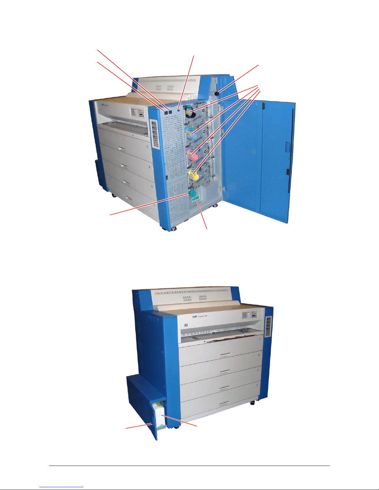
1. 5 Appearance
1. 5. 1 Front view
Power Switch
Bypass Feeder
Roll Decks
Name of part Function
Power Switch Turns on the KIP Color 80.
Bypass Feeder Feeds in the cut sheet media.
50 sheets can be set at once if the media is A2 (594mm) or
smaller. (24” or narrower)
Operation Panel Indicates information like printer status, error, mis-feed location
and etc.
Roll Decks 4 rolls of media can be installed.
Media / Toner
Information Panel
Right Side Door Can access the mis-fed media by opening Right Side Door.
Indicates the information about media (size, type & remaining
level) and toner (remaining level).
Operation Panel
Right Side Door
Media & Toner Information Panel
1-8
Page 14
1. 5. 2 Right side view
Counter B Dehumidify Heater Switch
Counter A
Cutter Handle
Waste Toner Door Waste Toner Box
Dust Tray
Fuser Handle
Toner Cartridge
1-9
Page 15

Name of part Function
Cutter Handle Can manually cut the mis-fed media rotating the Cutter Handle.
Fuser Handle Can remove the mos-fed media from the Fuser Region safely.
Dust Tray Collects the paper dust generated inside of the machine. Dust can
be disposed by pulling out the Dust Tray.
Counter A Counts the linear meter (linear feet - NA) of total prints.
Counter B Counts the square meter (square feet - NA) of total prints.
Dehumidify Heater
Switch
Can turn on the Dehumidify Heater by pressing the “H” side, and
turn it off by pressing the “L” side
Fuser Handle Can eject mis-fed media from the Fuser Unit by rotating the Fuser
Handle when the media is mis-fed in the Fuser Unit.
Toner Cartridge 4 Toner Cartridges (cyan, magenta, yellow and black)
Waste Toner Door Can access the Waste Toner Box by opening the Waste Toner
Door.
Waste Toner Box Collects the wasted toner.
1-10
Page 16
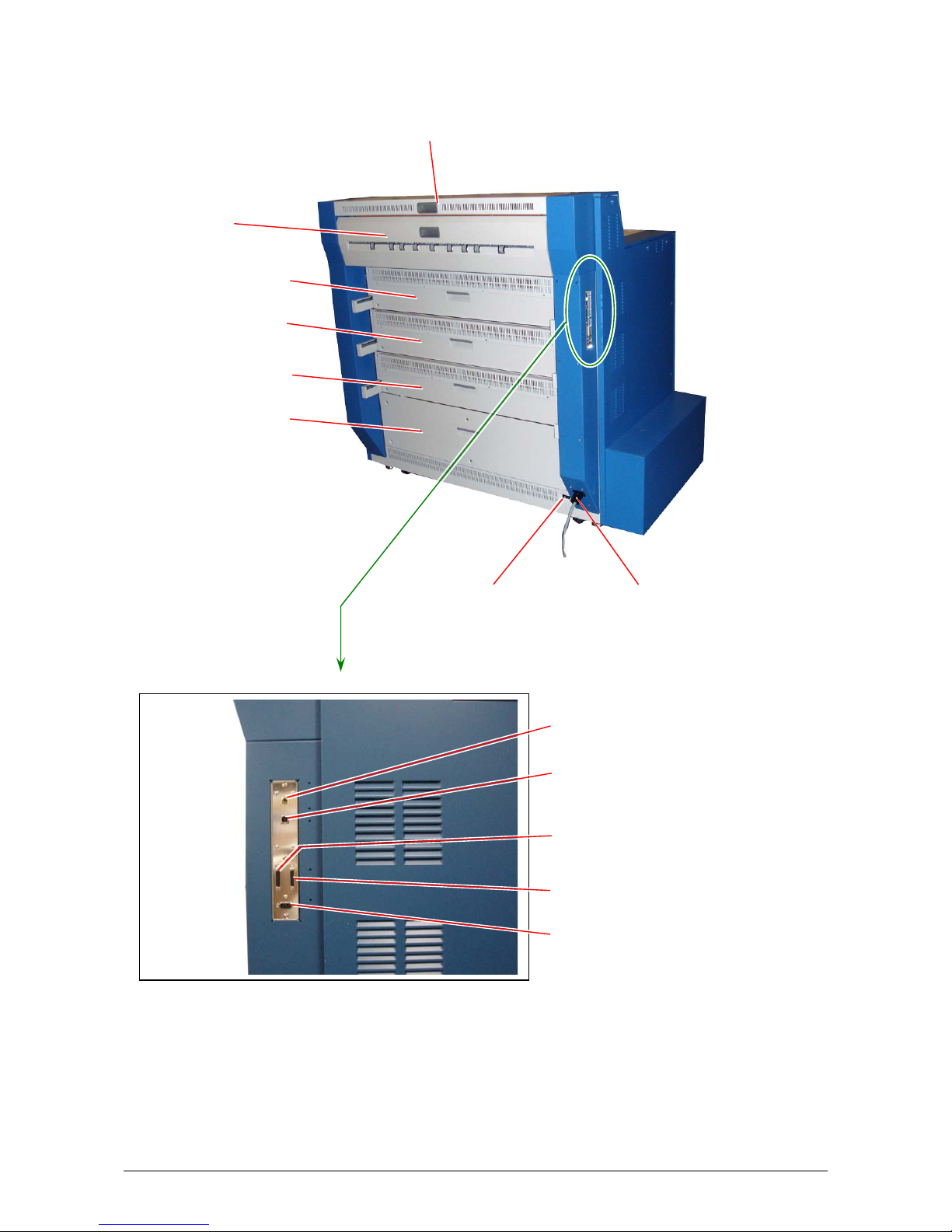
1. 5. 3 Rear view
Fuser Cover
Transportation Unit 1
Transportation Unit 2
Transportation Unit 3
Transportation Unit 4
Fuser Upper Cover
AC Main Switch Power Cord
Stacker Communication Port
USB PC Port
(For Service use only)
Not used (Interface VIII A )
Interface VIII B (for KCS)
Not used - (Folder Port)
1-11
Page 17

Name of part Function
Fuser Upper Cover Can access the media mis-fed around the entrance of the Fuser
Unit.
Fuser Cover Can access the media mis-fed around the Fuser Unit by opening the
Fuser Cover.
Transportation Unit 1 Can access the media mis-fed around the Transportation Unit 1.
Transportation Unit 2 Can access the media mis-fed around the Transportation Unit 2.
Transportation Unit 3 Can access the media mis-fed around the Transportation Unit 3.
Transportation Unit 4 Can access the media mis-fed around the Transportation Unit 4.
Power Cord To be connected to the wall outlet alone.
NOTE : Specification for the power cord used in North America
Use the following type of power cord (UL-Listed).
(1) Rating 250VAC, 20A
(2) Plug type NEMA6-20
(3) Socket type IEC60320 : C19
(4) Cord SJT 3xAWG12 L <4.5m
(5) UL-Listed
AC Main Switch Supplies or shuts off the AC main power.
Stacker Communication
Port
Connect the signal cable from the Auto Stacker. Connector type is
RJ11 : 5VDC max
(NOTE : Do not connect a telephone line.)
PC Port
(Service use only)
Interface VIII A
Interface VIII B (for
KCS)
Service personnel only use this port :
USB 2.0 Type B male : 5VDC max
Not Used
MDR Connector 36 pins : 3.3VDC max
Connect the signal cable from the PC unit.
MDR Connector 36 pins : 3.3VDC max
Folder Port Not Used
1-12
Page 18

1. 5. 4 Operation Panel
The Operation Panel on the upper right of front face is available for several settings. It also
indicates several status of KIP Color 80.
1 2 3 6 4 7 8 9 10 11 5
Paper Deck
2 3 4
1
Selec t Cut
Copy Density
K
C
M
Y
MF
D1
D2
D3
D4
D5
12 13 14 18 15 16 17
No. Name of part Function Refer to
1 Roll Deck Selection
Indicator
2 Roll Deck Selection
Indicates the present selection of Roll Deck for Initial
Cut.
Selects one Roll Deck for Initial Cut. 1-40
Key
3 Cut Key Makes an Initial Cut for the roll media on the selected
Roll Deck.
4 Wire-Clean Key Starts wire cleaning operation to prevent any image
problem. Lights when ready for wire cleaning, flashing
for cleaning, off for disabled for cleaning
5 Ready Indicator Flashes green when the KIP Color 80 is warming up.
Lights green when the KIP Color 80 gets ready.
6 Open Indicator Lights orange when any door or unit is open or
unlocked.
7 Web Cleaner Empty
Indicator
Flashes red when the Web Cleaner is near empty.
Lights red when the Web Cleaner is emptied completely
and no more copy/print become available.
8 Toner Empty
Indicator
Lights red when the toner is emptied completely and no
more copy/print become available.
9 Roll Empty Indicator Lights red when the roll media in use is emptied. 1-19
10 Mis-feed Indicator Lights red when a printing media is mis-fed.
(A mis-feed code like “J-xxxx” is indicated on the Status
Display and some indication LED of Mis-feed Location
Indicator lights red to inform the location of mis-feed.)
11 Waste Toner Full
Indicator
Lights red when the Waste Toner Box is filled with the
toner or when it is not installed correctly.
12 Density Indicator Indicates the density level presently selected by the
Copy Density Key.
13 Copy Density Key Can change the density level to make the printed image
lighter or darker.
D10
D9
D8
D7
D6
W ire-Clean
Menu Ent er Online
page;
1-40
1-40
1-140
1-16
1-120
1-131
1-132
1-30
1-132
1-133
1-74
1-134
1-135
-
-
1-13
Page 19

No. Name of part Function Refer to
14 Mis-feed / Open
Location Indicator
Indicates the location of mis-fed media by lighting any
LED in red.
Indicates the location of open door or open unit by
lighting any LED in orange.
15 Menu Key
These keys are used in the User Modes. Key
Key
Key
Enter Key
16 Online Key Lights when the KIP Color 80 is online, and goes off
when offline.
17 Online Indicator Switches between online and offline.
Cancels the User Mode.
Flashes during Warm / Cold Sleep mode.
18 Status Display Indicates error code, mis-feed code and other
information.
page;
1-74
-
-
-
1-14
Page 20

1. 5. 5 Media & Toner Information Panel
The Media & Toner Information Panel indicates the information of roll media on each Roll Deck
and that of toner of each color independently.
Media Type Indicator
1
Media Size Indicator
In Use Indicator
Roll Level Indicator
Roll Level
2
Roll Level
3
Roll Level
4
Roll Level
Toner Level
Toner Level
Toner Level Indicator
Toner Level
Toner Level
No. Name of part Function
1 Media Size Indicator Indicates the size of roll media installed on each Roll Deck.
2 Media Type Indicator Indicates the type of roll media installed on each Roll Deck.
3 Roll Level Indicator Indicates how much the roll media in the concerning Roll
Deck is remaining by 4 levels.
4 In Use Indicator Notices that the concerning Roll Deck must not be opened as
it is in use.
5 Toner Level Indicators Indicates how much the toner of each color is remaining by 4
levels.
Plain Paper
Vellum/Tracing
Film
Gloss
Plain Paper
Vellum/Tracing
Film
Gloss
Plain Paper
Vellum/Tracing
Film
Gloss
Plain Paper
Vellum/Tracing
Film
Gloss
In Use
In Use
In Use
In Use
1-15
Page 21

2 Operation Details
2. 1 Turning on the KIP Color 80
1. Plug the KIP Color 80 to a dedicated wall outlet.
NOTE
Please confirm the outlet satisfies the following condition before plugging the KIP Color 80
into.
220 - 240V (+6% to -10%), 20A, and 50/60Hz
2. Press “|” side of the AC Main Switch on the rear to supply the KIP Color 80 with AC voltage.
3. Press “|” side of the Power Switch on the front to turn on the KIP Color 80.
AC Main Switch
Power Switch
1-16
Page 22

4. KIP Color 80 starts warming up.
The Ready Indicator on the operation Panel flashes green during warming up.
Ready Indicator
Paper Deck
2 3 4
1
Selec t Cu t
Copy Density
K
C
M
Y
MF
D1
D2
D3
D4
D5
D10
D9
D8
D7
D6
Wi re- Cl ea n
Menu Enter Online
NOTE
The Wire-Clean Key may flash synchronized with the Ready Indicator. Wire Cleaning is
performed when it is flashing. Refer to [1.3.6.2 Flash of Wire-Clean Key] on page 1-137 for the
detail.
5. KIP Color 80 will get ready about 6 minutes after turning on.
The Ready Indicator stops flashing and lights green when ready.
1-17
Page 23
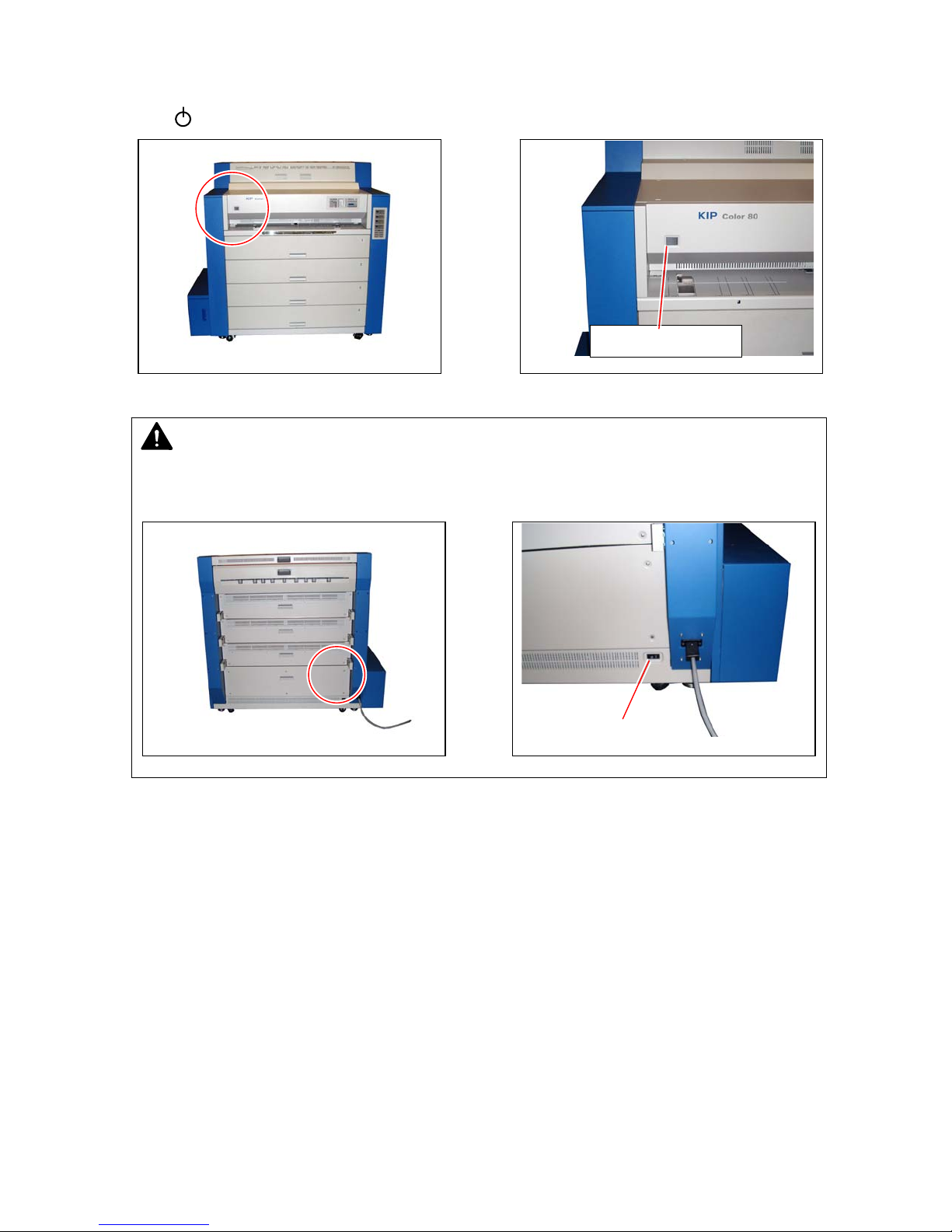
2. 2 Turning off the KIP Color 80
Press “ ” side of the Power Switch on the front to turn off the KIP Color 80.
NOTE
If you will disconnect the power cord, turn off the AC Main Switch at first pressing “O” side
then disconnecting the power cord.
AC Main Switch
Power Switch
1-18
Page 24

2. 3 Replacing the Roll Media
The Roll Empty Indicator lights red when the used roll media is emptied during printing.
Install a new roll media as instructed in below.
Roll Empty Indicator
Paper Deck
2 3 4
1
Selec t Cu t
Copy Density
K
C
M
Y
MF
D1
D2
D3
D4
D5
Reference
(1) Even if the KIP Color 80 is printing, a Roll Deck may be able to open without
interrupting the printing operation for replacing the roll media.
Whether a certain Roll Deck can be opened or not is shown by the corresponding”In Use”
indicator.
A Roll Deck can be opened for replacing the roll media even during printing if the
concerning In Use Indicator is not lighting.
Do not open the Roll Deck when its In Use Indicator is lighting.
Refer to the [1.3.6.3 “In Use” Indicator] on page 1-138 for further detail.
(2) The Roll Empty Indicator informs just “any” roll media is empty. Check the Roll Level
Indicator on the Media & Toner Information Panel to know which of 4 roll media is empty.
Media Size Indicator, Media Type Indicator and all of 4 LED of the Roll Level Indicator go
off if the concerning roll media is empty.
All the indicators go off when empty
(3) A new roll paper can be installed by the common method to all of 4 Roll Decks.
1
Roll Level
Plain Paper
Vellum/T ra cing
Film
Gloss
D10
D9
D8
D7
D6
Wi r e- Cl ea n
Menu Enter Online
In Us e
1-19
Page 25

1. Pulling up the handle to unlock the Roll Deck, and
draw out the deck.
Handle
2. Rotate the Roll Spool one revolution in the direction of arrow to put it out of gear, and then
remove it from the Roll Deck.
Spool
NOTE
The Roll Spool is in gear if not rotated in the
direction of arrow. The gear on the left end of the
Roll Spool will be broken if you remove the Roll
Spool without putting it out of gear.
This gear will be broken
1-20
Page 26
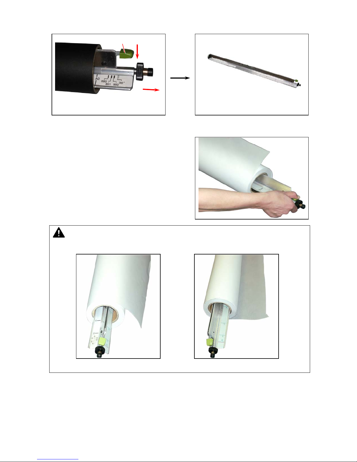
3. Pressing down the green lever to release the core of roll media, and pull out the Roll Spool
from the core.
Lever
4. Pressing down the green lever, insert the Roll
Spool into the new roll media.
NOTE
Set the roll media in the correct direction.
Correct Not correct
1-21
Page 27
5. Align the edge of roll media with the concerning
size guide, and then release the green lever to
fix the roll media onto the Roll Spool firmly.
6. Install the Roll Spool into the Roll Deck.
NOTE
The driving rubber belt on the right must be surely
placed under the black cylinder of the Roll Spool.
Paper feeding problem will occur if it is not under
the black cylinder as the following incorrect case.
Black cylinder Driving belt
Correct Incorrect
Size guide
1-22
Page 28

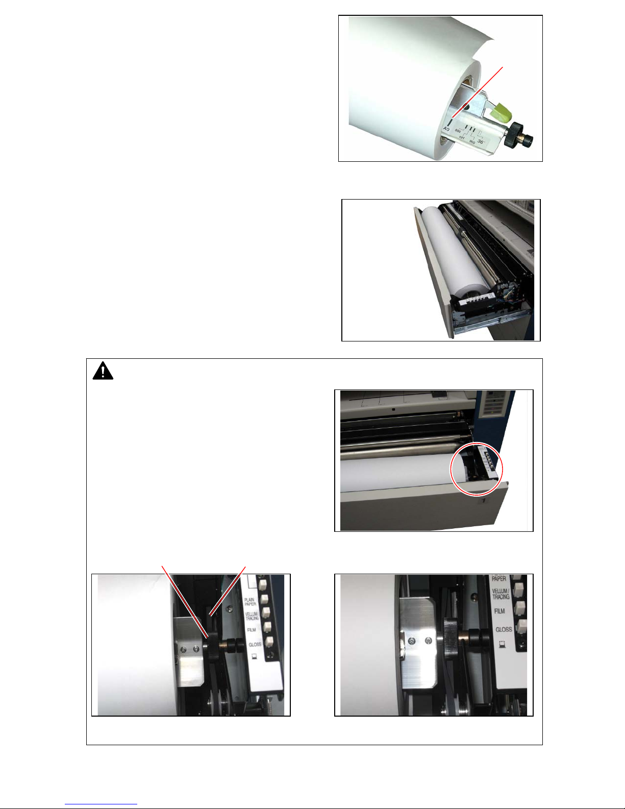
7. As there is a slit for receiving a cutter knife on each Roll Deck, cut off the leading part of roll
media to straighten the leading edge.
Slit
Cutter knife
8. Insert the leading edge of roll media between both feeding rollers, and rotate the upper feeding
roller to feed the roll media about 1 or 2cm.
Feeding rollers
1-23
Page 29
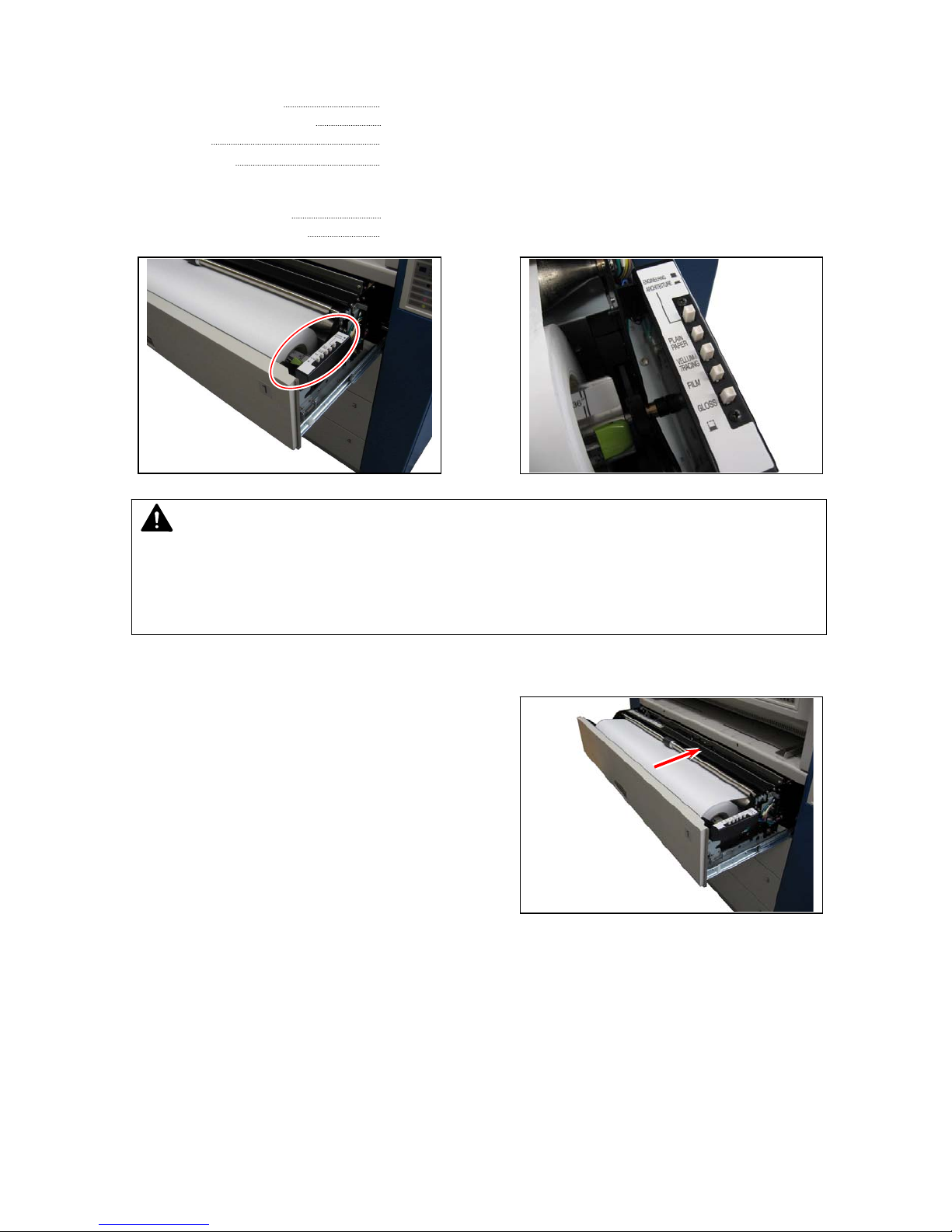
9. Media Selector is on the right of the Roll Deck.
Press any of “PLAIN PAPER”, “VELLUM / TRACING”, “FILM” and “GLOSS” according to the
type of the installed media.
PLAIN PAPER Select when bond (plain) paper is installed.
VELLUM/TRACING Select when vellum (tracing paper) is installed.
FILM Select when film is installed.
GLOSS Select when glossy paper is installed.
Select either “ENGINEERING” or “ARCHITECTURE” according to the format as well.
ENGINEERING Selected when the switch is up.
ARCHITECTURE Selected when the switch is down.
NOTE
Do not make a wrong selection on these switches.
A wrong setting for the type of media will lead to an unstable image (fusing defect) or some
other quality problem.
A wrong setting for the format of media will lead to a wrong image placement on the media.
10. Close the Roll Deck until it is locked firmly.
11. Set / confirm the type of media on the KIP Color Server (PC).
1-24
Page 30

2. 4 Setting Cut Sheet Media to Bypass Feeder
Cut sheet media can be fed from the Bypass Feeder.
Each size has its own availability for orientation and multi-feeding respectively as follows.
Metric
Media size Available orientation
A4 Landscape
A3 Landscape
A2 Landscape
A1 Landscape
A0 Portrait
841mm wide
(Not standard length)
(Length x Width)
(210mm x 297mm)
(297mm x 420mm)
(420mm x 597mm)
(597mm x 841mm)
(1189mm x 841mm)
Portrait & Landscape Not available Must be longer than 440mm at least.
Inch
Media size
(Length x Width)
8.5” x 11” Landscape Available
9” x 12” Landscape Available
11” x 17” Landsca pe Available
12” x 18” Landsca pe Available
17” x 22” Landsca pe Available
18” x 24” Landsca pe Available
30” wide
(Not standard length)
34” wide
(Not standard length)
36” wide
(Not standard length)
Available orientation Availability of
Portrait & Landscape Not available Must be longer than 440mm at least.
Portrait & Landscape Not available Must be longer than 440mm at least.
Portrait & Landscape Not available Must be longer than 440mm at least.
NOTE
(1) Availability of orientation for each media size is
illustrated on the Bypass Feeder.
Please follow the illustration when setting the
cut sheet media.
Landscape Portrait
(2) Multi-feeding is available when a small size of cut sheet media is used.
Refer to [1.2.4.1 Multi-feeding of cut sheet media ] on the page 1-26.
Availability of
multi-feeding
Available
Available
Available
Not available
Not available
multi-feeding
Remarks
Remarks
1-25
Page 31

2. 4. 1 Multi-feeding of cut sheet media
Multi-feeding is available when a small cut sheet media is used.
“Small sizes” are as follows.
Metric : A4 (210mm x 297mm) Inch : 8.5” x 11” 12” x 18”
A3 (297mm x 420mm) 9” x 12” 17” x 22”
A2 (420mm x 594mm) 11” x 17” 18” x 24”
NOTE
(1) Do not attempt to make multi-feeding with a wider media than the above ones as it will
cause a mis-feed or duplicate feeding. The internal mechanism might be broken in the
worst case.
(2) Do not leave the cut sheet media for a long time on the Bypass Feeder as it will get
moisture, which will result in a mis-feed or image defect. (Put the media in a vinyl bad to
block the moisture.)
(3) Only landscape position is available in case of multi-feeding.
1. Select the cut sheet feeding mode on the output device connected to the KIP Color 80.
Refer to your system reference for media source information.
2. Sliding left and right, place the cut sheet guides
properly according to the size of cut sheet media.
Cut sheet guides
1-26
Page 32

3. Arrange the edges of multiple media, put them on the Bypass Feeder by landscape position,
and move them forward until contacted to feeding roller.
Feeding roller
NOTE
As curled cut sheet media will cause a mis-feed, straighten the media as far as possible
before printing. And set the media by “curl down” direction as a mis-feed can be avoided.
Setting of media by “curl up” direction tends to result in a mis-feed.
Correct (curl down) Incorrect (curl up)
4. Output a copy/print job from the output device.
1-27
Page 33

2. 4. 2 Singular feeding of cut sheet media
A large cut sheet media can not be fed by multi-feeding.
Please feed it singularly as instructed in below.
“Large sizes” are as follows.
Metric : A1 landscape (210mm x 297mm) Inch : 30” wide (Not standard length)
A0 portrait (1189mm x 841mm) 34” wide (Not standard length)
841mm wide (Not standard length) 36” wide (Not standard length)
NOTE
Do not leave the cut sheet media for a long time on the Bypass Feeder as it will get moisture,
which will result in a mis-feed or image defect. (Put the media in a vinyl bad to block the
moisture.)
1. Select the cut sheet feeding mode on the output device connected to the KIP Color 80.
Refer to your system reference for media source information.
2. Sliding left and right, place the cut sheet guides
properly according to the size of cut sheet media.
3. Put the media on the Bypass Feeder, and move it in the direction of arrow until contacted to
the feeding roller.
The feeding rollers rotate automatically to place the cut sheet media at the starting position.
4. Output a copy/print job from the output device.
Feeding roller
Cut sheet guides
1-28
Page 34

NOTE
As curled cut sheet media will cause a mis-feed, straighten the media as far as possible
before printing.
And also please set the media by “curl down” direction as a mis-feed can be avoided.
Setting of media by “curl up” direction tends to result in a mis-feed.
Correct (curl down) Incorrect (curl up)
1-29
Page 35

2. 5 Replacing the Toner Cartridge
The Toner Empty Indicator on the Operation Panel lights red when any of 4 Toner Cartridges is
empty. On the Media & Toner Information Panel, the Toner Level Indicator informs which color of
Toner Cartridge is empty as all of 4 lamps go off when the concerning color of cartridge is empty.
As printing is not available until the cartridge is replaced, replace it as instructed on and after the
next page.
Paper Deck
2 3 4
1
Select Cut
Copy Density
K
C
M
Y
MF
D1
D2
D3
D4
D5
Toner Empty Indicator
NOTE
If very dark image is printed consuming great amount of
toner, the Toner Empty indicator may rarely light even
though the Toner Cartridge still has enough toner. If this
cartridge is installed again, the Toner Empty Indicator
will stop lighting and you will be able to continue printing.
Therefore make sure to check if the toner is still
remaining in the cartridge whenever you remove the
cartridge.
Toner Level Indicator
(Example : Yellow cartridge is empty.)
D10
D9
D8
D7
D6
Wi re- Cl ean
Menu Enter Online
1
Roll Level
2
Roll Level
3
Roll Level
4
Roll Level
Toner Level
Toner Level
Toner Level
Toner Level
Plain Paper
Vellum/Tracing
Film
Gloss
Plain Paper
Vellum/Tracing
Film
Gloss
Plain Paper
Vellum/Tracing
Film
Gloss
Plain Paper
Vellum/Tracing
Film
Gloss
In Use
In Use
In Use
In Use
1-30
Page 36

1. Open the Right Side Door.
2. Rotate the Toner Cartridge 180 degrees in the direction of arrow until it is stopped.
Remove the Toner Cartridge from the machine.
Toner Cartridge
NOTE
(1) Toner Cartridge can not be removed if not rotated 180 degrees completely as the above.
(2) Do not hold the ventral region of Toner Cartridge. Otherwise the toner may blow out from
the supplying hole.
(3) Be careful not to direct the supplying hole to the floor after removing the Toner Cartridge.
Otherwise toner will come out from the supplying hole.
(4) Do not remove Toner Cartridge with unused
toner portion inside. Otherwise the toner portion
may come out from the supplying hole.
WARNING
Dispose the used Toner Cartridge properly. Excess heat /sparks/flames may cause it explode!
Right Side Door
Supplying hole
1-31
Page 37

3. Choose the new Toner Cartridge of the same color, and shake it well to loosen the toner.
4. Insert the Toner Cartridge into the machine with
its green seal up.
Green seal
5. Rotate the Toner Cartridge 180 degrees in the direction of arrow until it is stopped.
1-32
Page 38

6. Strip off the green seal to open the cartridge.
Green seal
NOTE
Toner Empty Indicator will light soon if the supplying hole is directed upward or, if green seal
is not removed.
7. Close the Right Side Door.
Right Side Door
1-33
Page 39

2. 6 Replacing the Waste Toner Box
The Waste Toner Full Indicator on the Operation Panel lights red when the Waste Toner Box is
completely filled with the wasted toner. Printing is not available until the Waste Toner Box is
replaced>Replace it as instructed below.
Waste Toner Full Indicator
Paper Deck
2 3 4
1
Selec t Cu t
Copy Density
K
C
M
Y
MF
D1
D2
D3
D4
D5
1. Open the Waster Toner Door on the lower left.
D10
D9
D8
D7
D6
Wi r e- Cl ea n
Menu Enter Online
Waste Toner Door
1-34
Page 40

2. Remove the Waste Toner Box.
Waste Toner Box
NOTE
Do not handle the Waste Toner Box roughly. Otherwise the toner will come out from its open
hole.
3. Strip off the release paper beside the open hole.
Release paper
4. Close the open hold of the box with the white seal.
Dispose the Waste Toner Box in a correct way.
White seal
WARNING
Do not dispose the Waste Toner Box as a flammable. Toner will explode if thrown into the
fire. Please ask the seller for the way of dispose.
1-35
Page 41

5. Assemble a folded Waste Toner Box.
6. Strip off the protection papers on 3 tabs, and apply these 3 tabs to the side face of the box
folding inward. (1 of 4 tabs can not be applied.)
Rear side Front side
Tab Tab
This tab can not be applied.
1-36
Page 42

7. Holding the free tab, set the Waste Toner Box into
the machine so that the hole on the top of the box
is located on the rear side.
NOTE
(1) Direct the free tab upside. Otherwise it may
intervene to close the Waste Toner Door.
(2) Make sure that the hole on the top of Waste Toner Box is located on the rear side.
Otherwise it may cause the machine’s malfunction.
hole
8. Close the Waste Toner Door.
Waste Toner Door
1-37
Page 43

2. 7 Dehumidifying the Roll Media
A print defect may occur if the roll media is very humid. The usual defects are “crease of media”
and “lack of image”.
Roll media will become humid if it is kept in the Roll Deck for a long time, and will result in the
above types of issues. Turn on the Dehumidify Heater to dehumidify the roll media if the room has
too much humidity (higher than 60%RH). Then the above image issues should be resolved.
1. Open the Right Side Door.
Normal Print
Normal Print
Crease of media
When media is humidified;
Lack of image
When media is humidified;
Right Side Door
1-38
Page 44

2. Press the “H” side of the Dehumidify Heater Switch to turn on the Dehumidify Heater.
(Press the “L” side to turn off.)
Reference
(1) The Dehumidify Heater operates even if the Power Switch is OFF. Be careful not to
disconnect the power cord or not to turn off the AC Main Switch. The Dehumidify Heater
can not operate if unplugged.
(2) It is recommended for getting a better print quality to use a roll media right after it is
unpacked. The roll media will be more humid if exposed to the room air for longer
time.
Dehumidify Heater Switch
L
H
HL
1-39
Page 45

2. 8 Initial Cut
(Straighten the leading edge of roll media)
A new roll media tends to have a rough or folded leading edge. Initial Cut will easily straighten the
leading edge by cutting off such poor quality part of the media automatically. The selected roll
media is cut by 260mm long, and the portion of media after the cut is automatically ejected.
Roll Deck Selection Indicator (1), Roll Deck Selection Key (2), and Cut Key (3) are used for the
operation.
1 2 3
Paper Deck
2 3 4
1
Select Cut
Copy Density
K
C
M
Y
MF
D1
D2
D3
D4
D5
D10
D9
D8
D7
D6
Wire-Clean
Menu Enter On lin e
Operate as follows for making Initial Cut.
1. Select any Roll Deck number pressing the Roll Deck Selection Key. Green light turns on for the
selected Roll Deck number. Initial Cut will be done for selected roll media.
Pape r Deck
2 3 4
1
Select Cut
Pape r Deck
2 3 4
1
Select Cut
2. Press the Cut Key. The roll media of the selected Roll Deck is
automatically transported and its leading edge is cut off. The
portion of media after the cut is automatically ejected.
Pape r Deck
2 3 4
1
Select Cut
NOTE
When the KIP Color 80 is not available for the Initial Cut by
some reason like “warm up” or “door open”, all of 4 lamps of
the Roll Deck Selection Indicator go off.
Some Media manufactures / suppliers place tape or adhesive on the edge of the media to
prevent it from unrolling in the package. Any adhesive that remains on the media and is
transported through the printer will cause internal parts to become damaged or dirty.
Pape r Deck
2 3 4
1
Select Cut
REMOVE THIS AREA OF THE MEDIA MANUALLY PRIO R TO INSTALLING THE ROLL
IN THE PRINTER.
1-40
Page 46

2. 9 User Modes
KIP Color 80 provides 14 User Modes. Please note that not all of these modes are to be used
and are meant more for service functions.
User Mode No. Description User Mode
Code
User Mode 01 Test Print Start Mode 01.
User Mode 02 Warm Sleep Mode setting (ON/OFF, Timer) 02.
User Mode 03 Cold Sleep Mode setting (Timer) 03.
User Mode 04 Temporary clearance of E-2132 04.
User Mode 05 Temporary clearance of E-2232 05.
User Mode 06 Temporary clearance of E-2332 06.
User Mode 07 Temporary clearance of E-2432 07.
User Mode 08 Temporary clearance of E-2142 08.
User Mode 09 Temporary clearance of E-2242 09.
User Mode 10 Temporary clearance of E-2342 10.
User Mode 11 Temporary clearance of E-2442 11.
User Mode 12 Test Print setting – Output mode 12.
User Mode 13 Test Print setting - Selection of Roll Deck 13.
User Mode 14 Test Print setting - Selection of media type (type #X) 14.
All the operations in the User Mode are done on the following region of the Operation Panel.
Paper Deck
2 3 4
1
Selec t Cu t
Copy Density
K
C
M
Y
MF
D1
D2
D3
D4
D5
D10
D9
D8
D7
D6
Wi re- Cl ea n
Menu Enter Online
1-41
Page 47

2. 9. 1 User Mode 01 (Test Print Start Mode)
User Mode 01 can start a Test Print.
NOTE
When test print is started from User Mode 01, KC80 will perform test printing depending on
your specification for “output mode”, “roll deck” and “media type” which can be specified in
different user modes respectively. See the following sections for more details.
[1.2.9.12 User Mode 12 (Test Print setting – Output mode)] on page 1-64
[1.2.9.13 User Mode 13 (Test Print setting - Selection of Roll Deck)] on page 1-66
[1.2.9.14 User Mode 14 (Test Print setting - Selection of media type [type #X])] on page 1-68
[Operation]
1. Press the Menu Key once to select the User Mode 01. The Status Display indicates any of
“01.Poo”, “01.1oo” and “01.2oo”.
Menu Enter Online
Menu Enter Online
Menu Enter Online
Menu Enter Online
NOTE
The selection of output mode specified in User Mode 12 decides which code is indicated on
the LCD at this time. The LCD indicates;
• “01.Poo” when the output mode is set to “Prn” (Normal test print).
• “01.1oo” when the output mode is set to “C_1” (Color Registration V calibration).
• “01.2oo” when the output mode is set to “C_2” (Color Registration H calibration).
1-42
Page 48

2. Press the Enter Key to start test printing. The KIP Color 80 will perform test printing depending
on your test print settings. “Poo” (or “1oo”, “2oo”) on the Status Display flashes during printing.
Menu Enter Online
Menu Enter Online
NOTE
(1) Test print is not available when “- - -” lights.
(2) If test print is started with setting the output mode to “Color Registration V calibration”
(“1oo” on LCD) or “Color Registration H calibration” (“2oo”), KC80 will print out an
exclusive pattern on 3 different lengths of sheets. Color Registration V or H is calibrated
at this time. Ask your service personnel for the detail of Color Registrations V and H.
Menu Enter Online
3. Press the Online Key to cancel the User Mode 01.
Menu Enter Online
Menu Enter Online
NOTE
Online Key will cancel the User Mode 01 when in any stage of the setting.
1-43
Page 49

2. 9. 2 User Mode 02 (Warm Sleep Mode)
Warm Sleep Mode can be worked or cancelled, and the timer setting is available as well if Warm
Sleep Mode is worked.
Reference
Warm Sleep Mode is a kind of power saving mode. It works when the KIP Color 80 does not
print for the time the timer specifies. Power consumption is reduced by maintaining the
temperature of fuser at a lower degree than usual stand by state.
Warm Sleep Mode will be cancelled automatically when a print job or a copy job is sent from
the outer device. However it may take time until the KIP Color 80 starts printing as it needs to
recover enough temperature on the fuser. (Print does not start until the KIP Color 80 gets
ready recovering enough temperature.)
[Operation]
1. Press the Menu Key twice to select the User Mode 02.
Menu Enter Online
2. Press the Enter Key. The setting value on the right hand flashes and becomes changeable.
Menu Enter Online
3. ON/OFF selection for the Warm Sleep Mode can be specified at first. Select “On” for making
the Warm Sleep Mode work, and select “OFF” for cancelling it. “On” and “OFF” can be
switched with pressing [ ] and [ ] keys.
On : Warm Sleep ON (enabled)
OFF : Warm Sleep OFF (disabled)
Menu Enter Online Menu Enter On line
Menu Enter Online
Menu Enter Online
1-44
Page 50

4. Press the Enter Key to decide the ON/OFF setting. Then the next setting item “timer setting”
becomes available to change. (Setting will be finished when “oFF” was selected.)
Menu Enter Online
Menu Enter Online
5. Set the timer for the Warm Sleep Mode selecting a required time pressing [ ] and [ ] keys.
Selectable timers are 10, 15, 20, 30, 40, 50, 60, 90, 120, 180, and 240 minutes.
Menu Enter Online
Menu Enter Online
6. Decide the timer pressing the Enter Key. The setting value stops flashing when decided.
Menu Enter OnlineMenu Enter Online
7. Press the Online Key to cancel the User Mode 02.
Menu Enter Online
Menu Enter Online
NOTE
Online Key will cancel the User Mode 02 when in any stage of the setting. The setting value
on changing is not saved in this case.
1-45
Page 51

2. 9. 3 User Mode 03 (Cold Sleep Mode setting)
The timer setting for the Cold Sleep Mode is available.
Reference
(1) Cold Sleep Mode is a kind of power saving mode that can save more power than Warm
Sleep Mode. It works when the KIP Color 80 does not print for the time the timer specifies.
Power consumption is reduced greatly by completely shutting off supplying the power to
the fuser unit.
The Cold Sleep Mode will be cancelled automatically when a print job or a copy job is sent
from the outer device. However it may take time until the KIP Color 80 starts printing as it
needs to recover enough temperature on the fuser. (Print does not start until the KIP Color
80 becomes ready recovering enough temperature.) Note that the Cold Sleep Mode will
require
longer recovering time than Warm Sleep.
(2) Cold Sleep Mode works prior to the Warm Sleep Mode.
Supposing the timer is set as;
“30 minutes” for the Warm Sleep Mode
“15 minutes” for the Cold Sleep Mode
In this case the Cold Sleep Mode works 15 minutes later but the Warm Sleep Mode does
not work even if 30 minutes passes.
Supposing the timer is set as;
“15 minutes” for the Warm Sleep Mode
“30 minutes” for the Cold Sleep Mode
In this case the Warm Sleep Mode works 15 minutes later and the Cold Sleep Mode works
30 minutes later.
[Operation]
1. Press the Menu Key 3 times to select the User Mode 03.
Menu Enter Online
2. Press the Enter Key. The setting value on the right hand flashes and becomes changeable.
Menu Ente r Online
Menu Ente r Online
Menu Enter Online
1-46
Page 52

3. Set the timer for the Cold Sleep Mode selecting a required time pressing [ ] and [ ] keys.
Selectable timers are 10, 15, 20, 30, 40, 50, 60, 90, 120, 180, and 240 minutes.
Menu Enter Online
Menu Enter Online
4. Decide the timer pressing the Enter Key. The setting value stops flashing when decided.
Menu Enter Online
Menu Enter Online
5. Press the Online Key to cancel the User Mode 03.
Menu Enter Online
Menu Enter Online
NOTE
Online Key will cancel the User Mode 03 when in any stage of the setting. The setting value
on changing is not saved in this case.
1-47
Page 53

2. 9. 4 User Mode 04 (Temporary clearance of E-2132)
Service call error E-2132 might be temporarily cleared by easing the error check level, which may
avoid the breakdown of KIP Color 80.
Reference
The image quality (especially the color quality) varies according to the variation of temperature
of surrounding environment. To achieve a constant image quality in any environment, some
printing parameters are adjusted in real time according to the temperature condition. If the real
time adjustment can not work for some reason, any of service call errors E-2132, E-2232, E2332 and E-2432 is indicated and no more print becomes available.
As the user can not clear these errors, the KIP Color 80 will continue to be in breakdown until
the error is cleared by the service staff. But if the error can be temporarily cleared in the User
Mode 04 by easing the error check level, the KIP Color 80 will be relieved from breakdown
and you will be able to continue printing.
When you will clear the error by the User Mode 04 (and 05, 06, 07 as well), note that;
• Image quality may not be satisfactory as the real time adjustment does not work.
• There may be some case that the error can not be cleared even if you ease the error
1. Press the Menu Key 4 times to select the User Mode 04.
2. Press the Enter Key. The setting value on the right hand flashes and becomes changeable.
check level. Call the service staff immediately in this case.
• The User Mode 04 (and 05, 06, 07 as well) does not remove the real cause of error.
Therefore call the service staff as soon as possible although the KIP Color 80 seems to
be working fine.
Menu Enter Online Menu Enter On line
Menu Enter Online
Menu Enter Online
1-48
Page 54

3. Select “On” or “OFF” with pressing [ ] and [ ] keys.
On : Normal error check level
OFF : Low error check level
Menu Enter Online
Menu Enter Online
NOTE
Select “OFF” for cancelling the service call error E-2132.
4. Decide the setting pressing the Enter Key. The setting value stops flashing when decided.
Menu Enter Online
Menu Enter Online
5. Press the Online Key to cancel the User Mode 04.
Menu Enter Online
Menu Enter Online
NOTE
(1) Online Key will cancel the User Mode 04 when in any stage of the setting. The setting
value on changing is not saved in this case.
(2) The LCD will continue indicating the error code until the KIP Color 80 is rebooted.
6. Turn off/on the KC80 to reset the error code indication.
1-49
Page 55

2. 9. 5 User Mode 05 (Temporary clearance of E-2232)
Service call error E-2232 might be temporarily cleared by easing the error check level, which may
avoid the breakdown of KIP Color 80. Please see [Reference] on page 1-48 for the detail.
1. Press the Menu Key 5 times to select the User Mode 05.
2. Press the Enter Key. The setting value on the right hand flashes and becomes changeable.
3. Select “On” or “OFF” with pressing [ ] and [ ] keys.
On : Normal error check level
OFF : Low error check level
4. Decide the setting pressing the Enter Key. The setting value stops flashing when decided.
Menu Enter Online
Menu Enter Online
Menu Enter Online
Menu Enter Online
Menu Enter Online
Menu Enter Online
NOTE
Select “OFF” for cancelling the service call error E-2232.
Menu Enter Online
Menu Enter Online
1-50
Page 56

5. Press the Online Key to cancel the User Mode 05.
Menu Enter Online
Menu Enter Online
NOTE
(1) Online Key will cancel the User Mode 05 when in any stage of the setting. The setting
value on changing is not saved in this case.
(2) The LCD will continue indicating the error code until the KIP Color 80 is rebooted.
6. Turn off/on the KC80 to reset the error code indication.
1-51
Page 57

2. 9. 6 User Mode 06 (Temporary clearance of E-2332)
Service call error E-2332 might be temporarily cleared by easing the error check level, which may
avoid the breakdown of KIP Color 80. Please see [Reference] on page 1-48 for the detail.
1. Press the Menu Key 6 times to select the User Mode 06.
2. Press the Enter Key. The setting value on the right hand flashes and becomes changeable.
3. Select “On” or “OFF” with pressing [ ] and [ ] keys.
On : Normal error check level
OFF : Low error check level
4. Decide the setting pressing the Enter Key. The setting value stops flashing when decided.
Menu Enter Online
Menu Enter Online
Menu Enter Online
Menu Enter OnlineMenu Enter Online
Menu Enter Online
NOTE
Select “OFF” for cancelling the service call error E-2332.
Menu Enter Online
Menu Enter Online
1-52
Page 58

5. Press the Online Key to cancel the User Mode 06.
Menu Enter OnlineMenu Enter Online
NOTE
(1) Online Key will cancel the User Mode 06 when in any stage of the setting. The setting
value on changing is not saved in this case.
(2) The LCD will continue indicating the error code until the KIP Color 80 is rebooted.
6. Turn off/on the KC80 to reset the error code indication.
1-53
Page 59

2. 9. 7 User Mode 07 (Temporary clearance of E-2432)
Service call error E-2432 might be temporarily cleared by easing the error check level, which may
avoid the breakdown of KIP Color 80. Please see [Reference] on page 1-48 for the detail.
1. Press the Menu Key 7 times to select the User Mode 07.
2. Press the Enter Key. The setting value on the right hand flashes and becomes changeable.
3. Select “On” or “OFF” with pressing [ ] and [ ] keys.
On : Normal error check level
OFF : Low error check level
4. Decide the setting pressing the Enter Key. The setting value stops flashing when decided.
Menu Enter Online
Menu Enter Online
Menu Enter Online
Menu Enter Online
Menu Enter Online
Menu Enter Online
NOTE
Select “OFF” for cancelling the service call error E-2432.
Menu Enter Online
Menu Enter Online
1-54
Page 60

5. Press the Online Key to cancel the User Mode 07.
Menu Enter OnlineMenu Enter Online
NOTE
(1) Online Key will cancel the User Mode 07 when in any stage of the setting. The setting
value on changing is not saved in this case.
(2) The LCD will continue indicating the error code until the KIP Color 80 is rebooted.
6. Turn off/on the KC80 to reset the error code indication.
1-55
Page 61

2. 9. 8 User Mode 08 (Temporary clearance of E-2142)
Service call errors E-2142 might be temporarily cleared by easing the error check level, which may
avoid the breakdown of KIP Color 80.
Reference
The image quality (especially the color quality) varies according to the variation of temperature
of surrounding environment. To achieve a constant image quality in any environment, some
printing parameters are adjusted in real time according to the temperature condition. If the real
time adjustment can not work for some reason, any of service call errors E-2142, E-2242, E2342 and E-2442 is indicated and no more print becomes available.
As the user can not clear these errors, the KIP Color 80 will continue to be in breakdown until
the error is cleared by the service staff. But if the error can be temporarily cleared in the User
Mode 04 by easing the error check level, the KIP Color 80 will be relieved from breakdown
and you will be able to continue printing.
When you will clear the error by the User Mode 08 (and 09, 0A, 0b as well), note that;
• Image quality may not be satisfactory as the real time adjustment does not work.
• There may be some case that the error can not be cleared even if you ease the error
check level. Call the service staff immediately in this case.
• The User Mode 08 (and 09, 0A, 0b as well) does not remove the real cause of error.
Therefore call the service staff as soon as possible although the KIP Color 80 seems to
be working fine.
1. Press the Menu Key 8 times to select the User Mode 08.
Menu Enter Online
2. Press the Enter Key. The setting value on the right hand flashes and becomes changeable.
Menu Enter Online
Menu Enter Online
Menu Enter Online
1-56
Page 62

3. Select any of “OFF”, “On1” and “On2” with pressing [ ] and [ ] keys.
OFF : Low error check level
On1 : Normal error check level
On2 : High error check level
Menu Enter Online
Menu Enter Online
NOTE
Select lower error check level for cancelling the service call error E-2142.
4. Decide the setting pressing the Enter Key. The setting value stops flashing when decided.
Menu Enter Online
Menu Enter Online
5. Press the Online Key to cancel the User Mode 08.
Menu Enter Online
Menu Enter Online
NOTE
(1) Online Key will cancel the User Mode 08 when in any stage of the setting. The setting
value on changing is not saved in this case.
(2) The LCD will continue indicating the error code until the KIP Color 80 is rebooted.
6. Turn off/on the KC80 to reset the error code indication.
1-57
Page 63

2. 9. 9 User Mode 09 (Temporary clearance of E-2242)
Service call error E-2242 might be temporarily cleared by easing the error check level, which may
avoid the breakdown of KIP Color 80. Please see [Reference] on page 1-56 for the detail.
1. Press the Menu Key 9 times to select the User Mode 09.
Menu Enter Online
2. Press the Enter Key. The setting value on the right hand flashes and becomes changeable.
Menu Enter Online
3. Select any of “OFF”, “On1” and “On2” with pressing [ ] and [ ] keys.
OFF : Low error check level
On1 : Normal error check level
On2 : High error check level
Menu Enter Online
NOTE
Select lower error check level for cancelling the service call error E-2242.
4. Decide the setting pressing the Enter Key. The setting value stops flashing when decided.
Menu Enter Online
Menu Enter Online
Menu Enter Online
Menu Enter Online
Menu Enter Online
1-58
Page 64

5. Press the Online Key to cancel the User Mode 09.
Menu Enter Online
Menu Enter Online
NOTE
(1) Online Key will cancel the User Mode 09 when in any stage of the setting. The setting
value on changing is not saved in this case.
(2) The LCD will continue indicating the error code until the KIP Color 80 is rebooted.
6. Turn off/on the KC80 to reset the error code indication.
1-59
Page 65

2. 9.10 User Mode 10 (Temporary clearance of E-2342)
Service call error E-2342 might be temporarily cleared by easing the error check level, which may
avoid the breakdown of KIP Color 80. Please see [Reference] on page 1-56 for the detail.
1. Press the Menu Key 10 times to select the User Mode 10.
Menu Enter Online
2. Press the Enter Key. The setting value on the right hand flashes and becomes changeable.
Menu Enter Online
3. Select any of “OFF”, “On1” and “On2” with pressing [ ] and [ ] keys.
OFF : Low error check level
On1 : Normal error check level
On2 : High error check level
Menu Enter Online
NOTE
Select lower error check level for cancelling the service call error E-2342.
4. Decide the setting pressing the Enter Key. The setting value stops flashing when decided.
Menu Enter Online
Menu Enter Online
Menu Enter Online
Menu Enter Online
Menu Enter Online
1-60
Page 66

5. Press the Online Key to cancel the User Mode 10.
Menu Enter OnlineMenu Enter Online
NOTE
(1) Online Key will cancel the User Mode 10 when in any stage of the setting. The setting
value on changing is not saved in this case.
(2) The LCD will continue indicating the error code until the KIP Color 80 is rebooted.
6. Turn off/on the KC80 to reset the error code indication.
1-61
Page 67

2. 9.11 User Mode 11 (Temporary clearance of E-2442)
Service call error E-2442 might be temporarily cleared by easing the error check level, which may
avoid the breakdown of KIP Color 80. Please see [Reference] on page 1-56 for the detail.
1. Press the Menu Key 11 times to select the User Mode 11.
Menu Enter Online
2. Press the Enter Key. The setting value on the right hand flashes and becomes changeable.
Menu Enter Online
3. Select any of “OFF”, “On1” and “On2” with pressing [ ] and [ ] keys.
OFF : Low error check level
On1 : Normal error check level
On2 : High error check level
Menu Enter Online
NOTE
Select lower error check level for cancelling the service call error E-2442.
4. Decide the setting pressing the Enter Key. The setting value stops flashing when decided.
Menu Enter Online
Menu Enter Online
Menu Enter Online
Menu Enter Online
Menu Enter Online
1-62
Page 68

5. Press the Online Key to cancel the User Mode 11.
Menu Enter OnlineMenu Enter Online
NOTE
(1) Online Key will cancel the User Mode 11 when in any stage of the setting. The setting
value on changing is not saved in this case.
(2) The LCD will continue indicating the error code until the KIP Color 80 is rebooted.
6. Turn off/on the KC80 to reset the error code indication.
1-63
Page 69

2. 9.12 User Mode 12 (Test Print setting – Output mode)
It is possible to set the output mode of Test Print to any of the following 3.
Operation mode Description
Normal test print mode 1 sheet of internal test pattern is printed out. This is
a popular way of test printing, and used for checking
the printed image. (User can not specify the test
pattern.)
Color Registration V calibration mode 3 sheets of exclusive calibration pattern are printed
out in different paper length. Calibration of Color
Registration V is performed at the same time.
Color Registration H calibration mode 1 sheet of exclusive calibration pattern is printed out.
Calibration of Color Registration H is performed at
the same time.
NOTE
“Color Registration V” and “Color Registration H” are the calibration processes to place
4 color (CMYK) images correctly on the printing media. It is unnecessary for the user to
make these calibrations in usual situation. Rather, it is not recommended to make calibration
unless the service personnel ask you to do so.
Ask your service personnel for more detail about Color Registrations V and H.
1. Press the Menu Key 12 times to select the User Mode 12.
2. Press the Enter Key. The setting value on the right hand flashes and becomes changeable.
Menu Enter Online
Menu Enter Online
Menu Enter Online
Menu Enter Online
1-64
Page 70

3. Select any of “Prn”, “C_1” and “C_2” with pressing [ ] and [ ] keys.
Prn : Normal test print mode
C_1 : Color Registration V calibration mode
C_2 : Color Registration H calibration mode
Menu Enter Online
Menu Enter Online
4. Decide the setting pressing the Enter Key. The setting value stops flashing when decided.
Menu Enter Online
Menu Enter Online
5. Press the Online Key to cancel the User Mode 12.
Menu Enter Online
Menu Enter Online
NOTE
Online Key will cancel the User Mode 12 when in any stage of the setting. The setting value
on changing is not saved in this case.
1-65
Page 71

2. 9.13 User Mode 13 (Test Print setting - Selection of Roll Deck)
It is possible to select the Roll Deck used for test printing.
1. Press the Menu Key 13 times to select the User Mode 13.
2. Press the Enter Key. The setting value on the right hand flashes and becomes changeable.
3. Select any of “d1” to “d4” with pressing [ ] and [ ] keys.
d1 : Roll Deck 1
d2 : Roll Deck 2
d3 : Roll Deck 3
d4 : Roll Deck 4
4. Decide the setting pressing the Enter Key. The setting value stops flashing when decided.
Menu Enter Online
Menu Enter Online Menu Enter Online
Menu Enter Online
Menu Enter Online
Menu Enter OnlineMenu Enter Online
Menu Enter Online
1-66
Page 72

5. Press the Online Key to cancel the User Mode 13.
Menu Enter Online
Menu Enter Online
NOTE
Online Key will cancel the User Mode 13 when in any stage of the setting. The setting value
on changing is not saved in this case.
1-67
Page 73

2. 9.14 User Mode 14
(Test Print setting - Selection of media type [type #X])
It is possible to specify the media type (type #1 to 4) used for test printing.
1. Press the Menu Key 14 times to select the User Mode 14.
2. Press the Enter Key. The setting value on the right hand flashes and becomes changeable.
3. Select any of “1” to “4” with pressing [ ] and [ ] keys.
1 : Type #1
2 : Type #2
3 : Type #3
4 : Type #4
4. Decide the setting pressing the Enter Key. The setting value stops flashing when decided.
Menu Enter Online
Menu Enter Online
Menu Enter Online
Menu Enter Online
Menu Enter Online
Menu Enter Online
Menu Enter Online
Menu Enter Online
1-68
Page 74

5. Press the Online Key to cancel the User Mode 14.
Menu Enter Online
Menu Enter Online
NOTE
Online Key will cancel the User Mode 14 when in any stage of the setting. The setting value
on changing is not saved in this case.
1-69
Page 75

3 Error Messages
3. 1 General Outlines of Error Codes / Error
Indications
If any error occurs on the KIP Color 80, the error type and the location are shown on the Operation
Panel.
Error Indicator region indicates the type of error “by the illustration.
Mis-feed / Open Location Indicator region indicates the location of mis-feed error and open error.
The Status Display informs the description of error by indicating an error code.
Mis-feed / Open Location Indicator region Error Indicator region
Paper Deck
2 3 4
1
Select Cut
Copy Density
K
C
M
Y
MF
D1
D2
D3
D4
D5
Status Display
The following list shows all the possible error codes and error indications. See the reference page
for the solution.
Error Code / Error Indication Error Name Reference page
J-0101
J-0201
Mis-feed around the Roll Deck 1
Region
J-0401
J-0102
J-0202
Mis-feed around the Roll Deck 2
Region
J-0402
J-0103
J-0203
Mis-feed around the Roll Deck 3
Region
J-0403
J-0104
J-0204
Mis-feed around the Roll Deck 4
Region
J-0404
J-0105
J-0205
Mis-feed around the Bypass Feeder
Region
J-0405
J-0111
Mis-feed around the Cutter Region 1-89
J-0211
J-0411
D10
D9
D8
D7
D6
Wir e- Cl ean
Menu Enter Online
for the solution
1-76
1-79
1-82
1-85
1-88
1-70
Page 76

Error Code / Error Indication Error Name Reference page
for the solution
J-0112
J-0212
Mis-feed around the Bottom Corner
Region
1-92
J-0412
J-0121
J-0221
Mis-feed around the Transportation
Unit 1 Region
1-95
J-0421
J-0122
J-0222
Mis-feed around the Transportation
Unit 2 Region
1-100
J-0422
J-0123
J-0223
Mis-feed around the Transportation
Unit 3 Region
1-105
J-0423
J-0124
J-0224
Mis-feed around the Transportation
Unit 4 Region
1-110
J-0424
J-0131
Mis-feed in the Fuser Region 1-114
J-0231
J-0431
J-0181
Mis-feed in the Auto Stacker J-0281
J-0481
J-0182
Mis-feed in the Folder J-0282
J-0482
U-0101 Roll Deck 1 open 1-121
U-0102 Roll Deck 2 open 1-121
U-0103 Roll Deck 3 open 1-121
U-0104 Roll Deck 4 open 1-122
U-0110 Interlock open 1-122
U-0111 Bypass Feeder open 1-123
U-0112 Right Side Door open 1-123
U-0120 Transportation Unit 1 open 1-123
U-0121 Transportation Unit 2 open 1-124
U-0122 Transportation Unit 3 open 1-124
U-0123 Transportation Unit 4 open 1-124
U-0130 Fuser Cover open 1-125
U-0131 Fuser Upper Cover open 1-125
U-0140 Waste Toner Door open 1-125
U-0141 1-120
U-0142 1-120
U-0143 1-120
U-0144 1-120
U-0150 Waste Toner Box is not set 1-126
U-01A1 Folder Cover is open 1-126
Open Indicator
1-131
Web Cleaner Empty Indicator
Toner Empty Indicator
Roll Empty Indicator
Mis-feed Indicator 1-134
Waste Toner Full Indicator 1-135
1-71
1-132
1-132
1-133
Page 77

Error Code /
Error Indication
Error Name Reference page
for the solution
E-0001 Fuser temperature rising error 1-127
E-0002 Fuser abnormal high temperature error 1-127
E-0020 Fuser thermostat error 1-127
E-0011 Web feeding error 1-127
E-0051 Web end error 1-127
E-1012 Registration roller motor 4 error 1-127
E-1114 Transportation unit 1 motor error 1-127
E-1214 Transportation unit 2 motor error 1-127
E-1314 Transportation unit 3 motor error 1-127
E-1021 Cutter error 1-127
E-2010 Waste toner motor error 1-127
E-2111 Drum motor 1 error 1-127
E-2112 Developer motor 1 error 1-127
E-2113 Developer press motor 1 error 1-127
E-2114 Image corona 1 cleaning error (Delay) 1-127
E-2115 Image corona 1 cleaning error (Early) 1-127
E-2116 Image corona 1 cleaning error (Over current) 1-127
E-2117 Toner cartridge motor 1 error 1-127
E-2121 Image corona 1 output error 1-127
E-2122 Transfer corona 1 output error 1-127
E-2123 Separation corona 1 output error 1-127
E-2124 Developer bias 1 output error 1-127
E-2131 Surface potential sensor 1 error 1-127
E-2132 Automatic surface potential control 1 error 1-127
E-2141 Density sensor 1 error 1-127
E-2142 Automatic density control 1 error 1-127
E-2150 Developer unit 1 missing error 1-127
E-2161 Head 1 error (LED head unit 1) 1-127
E-2162 Head 2 error (LED head unit 1) 1-127
E-2163 Head 3 error (LED head unit 1) 1-127
E-2211 Drum motor 2 error 1-127
E-2212 Developer motor 2 error 1-127
E-2213 Developer press motor 2 error 1-127
E-2214 Image corona 2 cleaning error (Delay) 1-127
E-2215 Image corona 2 cleaning error (Early) 1-127
E-2216 Image corona 2 cleaning error (Over current) 1-127
E-2217 Toner cartridge motor 2 error 1-127
E-2221 Image corona 2 output error 1-127
E-2222 Transfer corona 2 output error 1-127
E-2223 Separation corona 2 output error 1-127
E-2224 Developer bias 2 output error 1-127
E-2231 Surface potential sensor 2 error 1-127
E-2232 Automatic surface potential control 2 error 1-127
E-2241 Density sensor 2 error 1-127
E-2242 Automatic density control 2 error 1-127
E-2250 Developer unit 2 missing error 1-127
E-2261 Head 1 error (LED head unit 2) 1-127
E-2262 Head 2 error (LED head unit 2) 1-127
E-2263 Head 3 error (LED head unit 2) 1-127
E-2311 Drum motor 3 error 1-127
E-2312 Developer motor 3 error 1-127
E-2313 Developer press motor 3 error 1-127
E-2314 Image corona 3 cleaning error (Delay) 1-127
E-2315 Image corona 3 cleaning error (Early) 1-127
E-2316 Image corona 3 cleaning error (Over current) 1-127
E-2317 Toner cartridge motor 3 error 1-127
1-72
Page 78

Error Code /
Error Name Reference page
Error Indication
E-2321 Image corona 3 output error 1-127
E-2322 Transfer corona 3 output error 1-127
E-2323 Separation corona 3 output error 1-127
E-2324 Developer bias 3 output error 1-127
E-2331 Surface potential sensor 3 error 1-127
E-2332 Automatic surface potential control 3 error 1-127
E-2341 Density sensor 3 error 1-127
E-2342 Automatic density control 3 error 1-127
E-2350 Developer unit 3 missing error 1-127
E-2361 Head 1 error (LED head unit 3) 1-127
E-2362 Head 2 error (LED head unit 3) 1-127
E-2363 Head 3 error (LED head unit 3) 1-127
E-2411 Drum motor 4 error 1-127
E-2412 Developer motor 4 error 1-127
E-2413 Developer press motor 4 error 1-127
E-2414 Image corona 4 cleaning error (Delay) 1-127
E-2415 Image corona 4 cleaning error (Early) 1-127
E-2416 Image corona 4 cleaning error (Over current) 1-127
E-2417 Toner cartridge motor 4 error 1-127
E-2421 Image corona 4 output error 1-127
E-2422 Transfer corona 4 output error 1-127
E-2423 Separation corona 4 output error 1-127
E-2424 Developer bias 4 output error 1-127
E-2431 Surface potential sensor 4 error 1-127
E-2432 Automatic surface potential control 4 error 1-127
E-2441 Density sensor 4 error 1-127
E-2442 Automatic density control 4 error 1-127
E-2450 Developer unit 4 missing error 1-127
E-2461 Head 1 error (LED head unit 4) 1-127
E-2462 Head 2 error (LED head unit 4) 1-127
E-2463 Head 3 error (LED head unit 4) 1-127
E-3001 Color Sensor error (Process 1) 1-127
E-3002 Color Sensor error (Process 2) 1-127
E-3003 Color Sensor error (Process 3) 1-127
E-3004 Color Sensor error (Process 4) 1-127
E-3011 Color Sensor reading error (Process 1) 1-127
E-3012 Color Sensor reading error (Process 2) 1-127
E-3013 Color Sensor reading error (Process 3) 1-127
E-3014 Color Sensor reading error (Process 4) 1-127
E-A001 Flash memory writing error 1-127
E-A010 IO board A communication error 1-127
E-A011 IO board B communication error 1-127
for the solution
1-73
Page 79

3. 2 Mis-feed Errors (Codes: J-xxxx)
If a mis-feed of printing media occurs anywhere in the KIP Color 80, the Mis-feed Indicator on the
Operation Panel lights red. The location of mis-feed is noticed by the lamp indication of the Misfeed / Open Location Indicator and the “mis-feed code” (J-xxxx) on the Status Display.
Mis-feed / Open Location Indicator Status Display (J-xxxx) Mis-feed Indicator
Paper Deck
2 3 4
1
Selec t Cu t
Copy Density
K
C
M
Y
MF
D1
D2
D3
D4
D5
LED lamp indication on the Mis-feed / Open Location Indicator and mis-feed codes on the Status
Display are related as follows. Refer to the page shown in the list for the solution of each mis-feed.
J-0121, J-0221 & J-0421 J-0131, J-0231 & J-0431
J-0122, J-0222 & J-0422
J-0101, J-0201 & J-0401
J-0123, J-0223 & J-0423
J-0102, J-0202 & J-0402
J-0124, J-0224 & J-0424
J-0103, J-0203 & J-0403
MF
D1
D2
D3
J-0104, J-0204 & J-0404 J-0112, J-0212 & J-0412
D4
J-0111, J-0211 & J-0411
Mis-feed
code
J-0101 J-0121
J-0201 J-0221
J-0401
J-0102 J-0122
J-0202 J-0222
J-0402
J-0103 J-0123
J-0203 J-0223
J-0403
J-0104 J-0124
J-0204 J-0224
J-0404
J-0111 J-0131
J-0211 J-0231
J-0411
J-0112
J-0212
J-0412
Location of mis-feed Refer to
page ;
Roll Deck 1 1-76
Roll Deck 2 1-79
Roll Deck 3 1-82
Roll Deck 4 1-85
Cutter Region 1-89
Bottom Corner Region 1-92
D5
Mis-feed
code
J-0421
J-0422
J-0423
J-0424
J-0431
D10
D9
D8
D7
D6
Wi r e- Cl ea n
Menu Enter Online
D10
D9
D8
D7
D6
Location of mis-feed Refer to
Transportation Unit 1 1-95
Transportation Unit 2 1-100
Transportation Unit 3 1-105
Transportation Unit 4 1-110
Fuser Region 1-114
page ;
1-74
Page 80

NOTE
(1) Some sheets of media may be staying in the KIP Color 80 simultaneously as the following
picture when mis-feed occurs during a continuous small size printing. Please check the
Operation Panel after removing one sheet of media. If the code remains, another media is
still staying in the machine. Remove all the remained media according to the reference
table in the previous page in the following section order “Fuser region”, “Transportation
Unit 1” and the specified “Roll Deck”.
1st sheet
3rd sheet
2nd sheet
(2) When open a unit on the rear to remove a jammed media, move a finishing device out of
the way for efficient operation.
1-75
Page 81

3. 2. 1 Mis-feed around the Roll Deck 1 Region
(Code: J-0101, J-0201 & J-0401)
When the roll media is mis-fed in the Roll Deck 1, any of J-0101, J-0201 and J-0401 is indicated.
(Refer to the following section picture for the location of mis-fed media.)
Roll Deck 1 region
Remove the mis-fed media as instructed in below.
1. Pull up the handle to unlock, draw out the Roll Deck 1.
2. Rewind the roll media rotating in the direction of
arrow.
Handle Roll Deck 1
1-76
Page 82

3. Straighten the leading edge by cutting off the
damaged part with a cutter knife.
NOTE
Please straighten the leading edge as the damaged edge will result in a mis-feed again.
4. Insert the leading edge of roll media between both feeding rollers, and rotate the upper feeding
roller to feed the roll media about 1 or 2cm.
Feeding Rollers
5. Close the Roll Deck 1.
Roll Deck 1
1-77
Page 83

6. Initial Cut is recommended to straighten the leading edge perfectly. Select the Roll Deck No.1
pressing the SELECT Key, and press the CUT Key to make the Initial Cut for the roll media in
the Roll Deck 1. (Details of the Initial Cut are described in [1.2.8 Initial Cut (Straighten the
leading edge of roll media)] on page 1-40.)
Select Key Cut Key
Paper Deck
2 3 4
1
Selec t Cu t
Copy Density
K
C
M
Y
MF
D1
D2
D3
D4
D5
D10
D9
D8
D7
D6
Wi re- Cl ea n
Menu Enter Online
1-78
Page 84

3. 2. 2 Mis-feed around the Roll Deck 2 Region
(Code: J-0102, J-0202 & J-0402)
When the roll media is mis-fed in the Roll Deck 2, any of J-0102, J-0202 and J-0402 is indicated.
(Refer to the following section picture for the location of mis-fed media.)
Roll Deck 2 region
Remove the mis-fed media as instructed in below.
1. Pull up the handle to unlock, draw out the Roll Deck 2.
2. Rewind the roll media rotating in the direction of
arrow.
Handle
Roll Deck 2
1-79
Page 85

3. Straighten the leading edge by cutting off the
damaged part with a cutter knife.
NOTE
Please straighten the leading edge as the damaged edge will result in a mis-feed again.
4. Insert the leading edge of roll media between both feeding rollers, and rotate the upper feeding
roller to feed the roll media about 1 or 2cm.
Feeding Rollers
5. Close the Roll Deck 2.
Roll Deck 2
1-80
Page 86

6. Initial Cut is recommended to straighten the leading edge perfectly. Select the Roll Deck No.2
pressing the SELECT Key, and press the CUT Key to make the Initial Cut for the roll media in
the Roll Deck 2. (Details of the Initial Cut are described in [1.2.8 Initial Cut (Straighten the
leading edge of roll media)] on page 1-40.)
Select Key Cut Key
Paper Deck
2 3 4
1
Select Cut
Copy Density
K
C
M
Y
MF
D1
D2
D3
D4
D5
D10
D9
D8
D7
D6
Wire-Clean
Menu Enter Online
1-81
Page 87

3. 2. 3 Mis-feed around the Roll Deck 3 Region
(Code: J-0103, J-0203 & J-0403)
When the roll media is mis-fed in the Roll Deck 3, any of J-0103, J-0203 and J-0403 is indicated.
(Refer to the following section picture for the location of mis-fed media.)
Roll Deck 3 region
Remove the mis-fed media as instructed in below.
1. Pull up the handle to unlock, draw out the Roll Deck 3.
2. Rewind the roll media rotating in the direction of
arrow.
Handle
Roll Deck 3
1-82
Page 88

3. Straighten the leading edge by cutting off the
damaged part with a cutter knife.
NOTE
Please straighten the leading edge as the damaged edge will result in a mis-feed again.
4. Insert the leading edge of roll media between both feeding rollers, and rotate the upper feeding
roller to feed the roll media about 1 or 2cm.
Feeding Rollers
5. Close the Roll Deck 3.
Roll Deck 3
1-83
Page 89

6. Initial Cut is recommended to straighten the leading edge perfectly. Select the Roll Deck No.3
pressing the SELECT Key, and press the CUT Key to make the Initial Cut for the roll media in
the Roll Deck 3. (Details of the Initial Cut are described in [1.2.8 Initial Cut (Straighten the
leading edge of roll media)] on page 1-40.)
Select Key Cut Key
Paper Deck
2 3 4
1
Select Cut
Copy Density
K
C
M
Y
MF
D1
D2
D3
D4
D5
D10
D9
D8
D7
D6
Wire-Clean
Menu Enter Online
1-84
Page 90

3. 2. 4 Mis-feed around the Roll Deck 4 Region
(Code: J-0104, J-0204 & J-0404)
When the roll media is mis-fed in the Roll Deck 4, any of J-0104, J-0204 and J-0404 is indicated.
(Refer to the following section picture for the location of mis-fed media.)
Roll Deck 4 region
Remove the mis-fed media as instructed in below.
1. Pull up the handle to unlock, draw out the Roll Deck 4.
2. Rewind the roll media rotating in the direction of
arrow.
Handle
Roll Deck 4
1-85
Page 91

3. Straighten the leading edge by cutting off the
damaged part with a cutter knife.
NOTE
Please straighten the leading edge as the damaged edge will result in a mis-feed again.
4. Insert the leading edge of roll media between both feeding rollers, and rotate the upper feeding
roller to feed the roll media about 1 or 2cm.
Feeding Rollers
5. Close the Roll Deck 4.
Roll Deck 4
1-86
Page 92

6. Initial Cut is recommended to straighten the leading edge perfectly. Select the Roll Deck No.3
pressing the SELECT Key, and press the CUT Key to make the Initial Cut for the roll media in
the Roll Deck 3. (Details of the Initial Cut are described in [1.2.8 Initial Cut (Straighten the
leading edge of roll media)] on page 1-40.)
Select Key Cut Key
Paper Deck
2 3 4
1
Select Cut
Copy Density
K
C
M
Y
MF
D1
D2
D3
D4
D5
D10
D9
D8
D7
D6
Wire-Clean
Menu Enter Online
1-87
Page 93

3. 2. 5 Mis-feed around the Bypass Feeder Region
(Code: J-0105, J-0205 & J-0405)
When the roll media is mis-fed in the Bypass Feeder, any of J-0105, J-0205 and J-0405 is
indicated. (Refer to the following section picture for the location of mis-fed media.)
Bypass Feeder region
NOTE
Mis-Feed / Open Location Indicator does not inform the location of the mis-feed in the
Bypass Feeder region because there is no concerning LED lamp.
Remove the mis-fed media as instructed in below.
1. Open both the Bypass Feeder and the Roll Deck 1, and remove the mis-fed media.
Bypass Feeder
Roll Deck 1
2. Close both the Bypass Feeder and the Roll Deck 1.
Bypass Feeder
Roll Deck 1
1-88
Page 94

3. 2. 6 Mis-feed around the Cutter Region
(Code: J-0111, J-0211 & J-0411)
When the roll media is mis-fed around the Cutter region, any of J-0111, J-0211 and J-0411 is
indicated. (Refer to the following section picture for the location of mis-fed media.)
Cutter region
Remove the mis-fed media as instructed in below.
1. Open the Transportation Unit 4 on the back.
Transportation
Unit 4
2. Check if the media is found inside of the machine. Whether or not the media is found decides
what to do next.
• If the media is found as the following left photo, proceed to the next procedure 3 to cut the
roll media.
• If it is not found, no more operation is required. Just close the Transportation Unit 4.
The concerned roll deck automatically rewinds the leading edge to the print start position.
Media is found Media is not found
Media
1-89
Page 95

3. Open the Right Side Door again, if it is closed.
4. Rotate the Cutter Handle one revolution in the direction of arrow to cut the roll media manually.
CAUTION
(1) Do not rotate the Cutter Handle to the other direction as the cutter blade may be broken.
(2) Do not rotate the Cutter Handle more than once. Otherwise it may result in paper feeding
malfunction.
5. Remove the media from the Transportation Unit 4
region.
NOTE
Initial Cut will be required on the later procedure as manual cutting by Cutter Handle can not
make the leading edge perpendicular to the side edge.
Right Side Door
Cutter Handle
1-90
Page 96

6. Close the Transportation Unit 4 and Right Side Door.
Right Side Door
Transportation Unit 4
NOTE
Close the Transportation Unit 4 surely and gently. The inside part of machine may be
damaged if closed roughly. And the Transportation Unit 4 may not be locked firmly if not
closed surely.
7. Initial Cut is recommended to straighten the leading edge perfectly. Select the concerning Roll
Deck Number pressing the SELECT Key, and press the CUT Key to make the Initial Cut.
(Details of the Initial Cut are described in [1.2.8 Initial Cut (Straighten the leading edge of roll
media)] on page 1-40.)
Select Key Cut Key
Paper Deck
2 3 4
1
Selec t Cu t
Copy Density
K
C
M
Y
MF
D1
D2
D3
D4
D5
D10
D9
D8
D7
D6
Wi r e- Cl ea n
Menu Enter Online
1-91
Page 97

3. 2. 7 Mis-feed around the Bottom Corner Region
(Code: J-0112, J-0212 & J-0412)
When the roll media is mis-fed around the Bottom Corner region, any of J-0112, J-0212 and
J-0412 is indicated. (Refer to the following section picture for the location of mis-fed media.)
Bottom Corner region
Remove the mis-fed media as instructed in below.
1. Open the Transportation Units 4. The mis-fed media will be found inside.
Transportation
Unit 4
NOTE
Make sure to open the Transportation Units before removing the mis-fed media. Otherwise the
inside of machine will become dirty with the toner.
2. Check if the mis-fed is cut or not by pulling it.
Whether the media is cut or not decides what to do
next.
• If the mis-fed media is cut and can be removed
from the machine easily, proceed to the
following procedure 3.
• If it has not been cut yet so can not be
removed from the machine, jump to the
procedure 4. (Procedure 3 is not needed.)
1-92
Page 98

3. After removing the mis-fed media from the Bottom Corner region, check if some more media is
g
found around there. Whether or not the media is found decides what to do next.
• If the media is found as the following left photo, proceed to the next procedure 4 to cut the
roll media.
• If it is not found, no more operation is required. Just close the Transportation Unit 4.
The concerned roll deck automatically rewinds the leading edge to the print start position.
Media is found Media is not found
4. Open the Right Side Door.
5. Rotate the Cutter Handle one revolution in the direction of arrow to cut the roll media manually.
CAUTION
(1) Do not rotate the Cutter Handle to the other direction as the cutter blade may be broken.
(2) Do not rotate the Cutter Handle more than once. Otherwise it may result in paper feeding
malfunction.
NOTE
Initial Cut will be required on the later procedure as manual cutting by Cutter Handle can not
make the leadin
Media
Right Side Door
Cutter Handle
edge perpendicular to the side edge.
1-93
Page 99

6. Remove the media from the Transportation Unit 4
region.
7. Close the Transportation Unit 4 and Right Side Door (if opened).
Right Side Door
Transportation Unit 4
NOTE
Close the Transportation Unit 4 surely and gently. The inside part of machine may be
damaged if closed roughly. And the Transportation Unit 4 may not be locked firmly if not
closed surely.
8. Initial Cut is recommended to straighten the leading edge perfectly. Select the concerning Roll
Deck Number pressing the SELECT Key, and press the CUT Key to make the Initial Cut.
(Details of the Initial Cut are described in [1.2.8 Initial Cut (Straighten the leading edge of roll
media)] on page 1-40.)
Select Key Cut Key
Paper Deck
2 3 4
1
Selec t Cu t
Copy Density
K
C
M
Y
MF
D1
D2
D3
D4
D5
D10
D9
D8
D7
D6
Wi r e- Cl ea n
Menu Enter Online
1-94
Page 100

3. 2. 8 Mis-feed around the Transportation Unit 1 Region
(Code: J-0121, J-0221 & J-0421)
When the roll media is mis-fed around the Transportation Unit 1 region, any of J-0121, J-0221 and
J-0421 is indicated. (Refer to the following section picture for the location of mis-fed media.)
Transportation Unit 1 region
Remove the mis-fed media as instructed in below.
1. Open all the Transportation Units 1 to 4. The mis-fed media will be found inside.
Transportation Unit 1
Transportation Unit 2
Transportation Unit 3
Transportation Unit 4
NOTE
Make sure to open the Transportation Units before removing the mis-fed media. Otherwise the
inside of machine will become dirty with the toner.
1-95
 Loading...