

Page 1
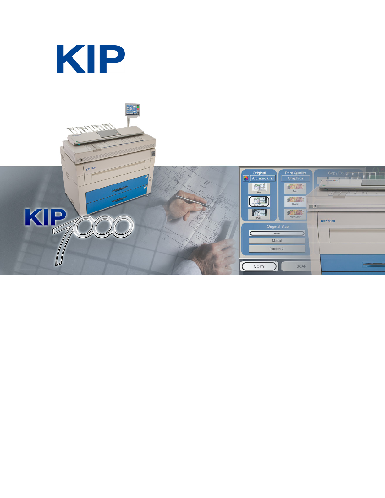
KIP 7000 User Guide
Version A.3
Page 2
Thank you for purchasing the KIP 7000.
This USER'S MANUAL contains functional and operational explanations for the KIP 7000.
Please read this USER'S MANUAL carefully before using the Printer.
Please keep this USER'S MANUAL for future reference.
1. When this product is installed in North America.
This device complies with part 15 of the FCC Rules. Operation is subject to the following two
conditions: (1) This device may not cause harmful interference, and (2) this device must
accept any interference received, including interference that may cause undesired operation.
2. When this product is installed in Europe
This equipment complies with the requirements in Pub.22 of CISPR Rules for a Class B
computing device.
Operation of this equipment in a residential area may cause unacceptable interference to radio
and TV reception requiring the operator to take whatever steps are necessary to correct the
interference.
Do not install Machine around other electronic equipment or other precision instruments.
Other devices may be effected by electrical noise during operation.
If the Machine is installed near other electronic equipment, such as a TV or a radio,
interference to said equipment, such as noise or flickering, may occur.
Use a separate power line and install the PRINTER as far as possible from said equipment.
As an ENERGY STAR ® Partner, Katsuragawa Electric Co., Ltd. has determined
that this product meets the
The International
promotes energy saving through the penetration of energy efficient computers and other office
equipment. The program backs the development and dissemination of products with functions that
effectively reduce energy consumption. It is an open system in which business proprietors can
participate voluntarily. The targeted products are office equipment such as computers, monitors,
printers, facsimiles, copiers, scanners, and multifunction devices. Their standards and logos are
uniform among participating nations.
The symbol shown indicates that this product conforms to
SJ/T11364-2006 of People’s Republic of China Electronic
Industry Standard and does not apply to countries outside of
People’s Republic of China.
The symbol shown indicates that this product conforms to GB
18455-2001 11364-2006 of National Standard of the People’s
Republic of China and does not apply to countries outside of
People’s Republic of China.
ENERGY STAR ® Office Equipment Program is an international program that
ENERGY STAR ® guidelines for energy efficiency.
(1)
Page 3

Safety Warnings
The following warnings are very important in order to safely use this product.
These notes are important in preventing danger to the operator or operation of the printer.
The following symbols are found throughout the USER’S Manual and have the following meaning:
WARNING
This WARNING mark means that there is a possibility of death or serious
injury if you ignore or do not follow the said instruction.
CAUTION
This CAUTION mark means that there is a possibility of injury or physical
damage if you ignore or do not follow the said instruction.
When marked with this symbol, “DO NOT ATTEMPT”
When marked with this symbol, “pay close attention to”
(2)
Page 4
WARNING
Ground the product with a correct ground source or you may be electrically
shocked.
1. The Power source should be as follows:
2. Use a circuit with a dedicated breaker.
3. Install the product as close to the wall outlet as possible.
4. If you wish to move the printer, please contact your service personnel.
1. Do not remove the screw and do not open the cover if not instructed to
do so in this User’s Manual. If you ignore this warning, you may be burnt
or receive an electric shock due to a hot item or electrically charged part
inside of the printer.
2. Do not disassemble or tamper with the printer.
It may result in a fire or an electrical shock.
1. Do not plug in the printer into a multi-wire connector in which some other
equipment is plugged into.
It may cause a fire due to outlet overheating.
2. Do not damage the Power Cord by stepping on or placing heavy items
on it.
If the Power Cord is damaged, it may cause a fire or you may receive
an electric shock. REPLACE THE CORD IF DAMAGED!
1. Do not put a flower vase, a flowerpot or any water-filled item on the
product.
Spilt water could cause a fire or an electric shock.
2. If the product generates an abnormal smell or noise, turn it off and
unplug it from the wall electrical outlet immediately.
Do not throw the toner into a fire or other sources of heat, as it can
explode.
220 – 240V plus 6% or minus 10%, 50/60Hz, 20A or higher
(3)
Page 5
CAUTION
Do not install the printer in a humidified room or a dusty room.
Also, do not install the printer on an unstable floor as injuries may occur.
1. Unplug the printer before you move it.
The power cord may be damaged and it may result in a fire or electric
shock.
Do not pull the cord when you unplug the printer as you may damage the
Power Cord.
There are hot items inside of the printer.
Take great care not to touch these items when you remove mis-fed media.
Ventilate the room well if you print in a small area.
2. If you do not use the printer for a long duration (holidays, company
shutdown) turn off and unplug the printer from the outlet for safety.
(4)
Page 6

TABLE OF CONTENTS
Part 1 Basic Functions
Part 2 Job Info Mode
Part 3 Help / Configuration Screen
Part 4 Windows Driver
Part 5 AutoCAD HDI Driver
Part 6 KIP Request
Part 7 KIP PrintNET
Part 8 Network Connectivity
(5)
Page 7

Part 1
Basic Functions
Page
Chapter 1 Before Use
1.1 Installation Requirements 1- 3
1.2 Originals Prohibited from Duplication 1- 4
1.3 Features 1- 5
1.4 Specifications 1- 6
1.5 Appearance 1- 7
1.5.1 Front view 1- 7
1.5.2 Rear view 1- 8
1.5.3 Operation Panel 1- 9
1.6 Indications during Normal Use 1-11
1.7 Optional Configurations 1-13
1.8 Specifications for the Printing Paper 1-15
1.8.1 Available Print Size 1-15
1.8.2 Media not to be used 1-16
1.8.3 Maintaining the Media 1-17
1.8.4 Environmental Condition - Correction 1-18
Chapter 2 Basic Operations
2.1 Turning on the KIP 7000 1-20
2.2 Turning off the KIP 7000 1-22
2.3 Replacing the Roll Media 1-23
2.4 Replacing the Toner Cartridge 1-32
2.5 Setting the Cut Sheet Paper 1-36
2.6 Dehumidifying the Roll Media 1-37
Chapter 3 Operations for the Useful Functions
3.1 Changing the Density Level 1-39
3.2 User Mode 1-40
3.2. 1 User Mode 0: (Reserved) 1-41
3.2. 2 User Mode 1: Image Enhancement Setting Mode 1-42
3.2. 3 User Mode 2: Auto Power Off Timer Setting Mode 1-44
3.2. 4 User Mode 3: Auto Power Off Setting Mode 1-45
3.2. 5 User Mode 4: Cold Sleep Timer Setting Mode 1-46
3.2. 6 User Mode 5: Cold Sleep Setting Mode 1-47
3.2. 7 User Mode 6: Warm Sleep Timer Setting Mode 1-48
3.2. 8 User Mode 7: Warm Sleep Setting Mode 1-49
3.2. 9 User Mode 8: (Reserved) 1-50
3.2.10 User Mode 9: L/L Environment Setting Mode 1-51
3.2.11 User Mode A: H/H Environment Setting Mode 1-53
3.2.12 User Mode b: High Coverage Setting Mode 1-55
3.2.13 User Mode C: (Reserved) 1-56
3.2.14 User Mode d: (Reserved) 1-57
Part 1 Basic Functions 1-1
Page 8
Chapter 4 Error Indications and Treatments
4.1 Paper Mis-feed Errors 1-58
4.1.1 Paper Mis-feed in the Roll Deck Section (J-01, J-02, J-03, J-04) 1-60
4.1.2 Paper Mis-feed in the Manual Feeder Section (J-05) 1-62
4.1.3 Paper Mis-feed in the Paper Feeder Section (J-10, J-11, J-12) 1-63
4.1.4 Paper Mis-feed in Fuser Section (J-13, J-14) 1-65
4.1.5 Paper Mis-feed in Outer Device (J-21, J-22) 1-68
4.2 Open Cover Errors 1-69
4.2.1 Roll Deck Open (U-01, U-02) 1-69
4.2.2 Upper Frame Unit / Top Cover Open (U-05) 1-71
4.2.3 Exit Cover Open (U-06) 1-72
4.3 Other Errors 1-73
4.3.1 Toner Low 1-73
4.3.2 Roll Empty 1-74
4.3.3 No Manual Paper (P.E.) 1-75
4.4 Call Service Errors 1-76
Part 1 Basic Functions 1-2
Page 9
Chapter 1 Before Use
1. 1 Installation Requirements
The following conditions are required for installation of the equipment.
1. Power source should be rated as follows.
220V - 240V plus 6% or minus 10%, 50/60Hz, 20A or higher
2. The equipment must be on an exclusive circuit.
3. The outlet must be near the equipment and easily accessible.
1. Make sure to connect this equipment to a grounded outlet.
2. For PLUGGABLE EQUIPMENT, the socket-outlet shall be installed near
the equipment and shall be easily accessible.
The site temperature range = 10 to 32 degrees Centigrade, with the humidity between
15% to 85% RH. (NON CONDENSING)
Keep the printer away from water sources, boilers, humidifiers or refrigerators.
1. The installation site must not have open flames, dust or ammonia gases.
2. The equipment must not be exposed to the air vents from air conditioners.
It may affect the image quality.
3. The equipment should not be exposed to the direct sunlight.
Please draw curtains to block any sunlight.
When you open the Movable Unit, do not expose the Photoconductive Drum
to strong (intense) light as this will damage the Drum.
Ozone will be generated while this equipment is use, although the quantity generated
is within safe levels. (see certifications)
Ventilate the room, if required.
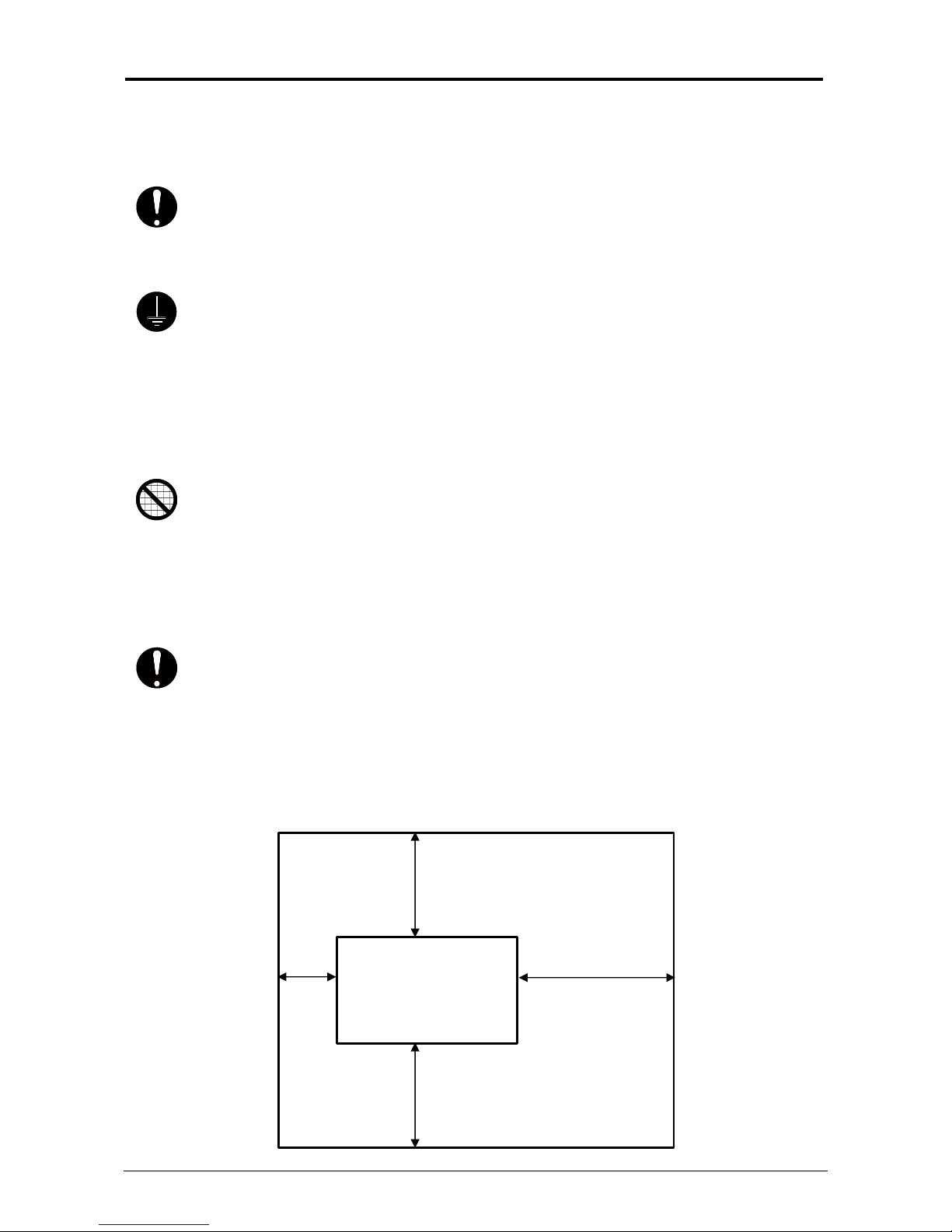
Keep ample room around the equipment to ensure comfortable operation.
(Refer to the following figure.)
The equipment must be levelled and the floor strength must be ample to sustain the
weight of the equipment.
80cm or wider
45cm 120cm or wider
or
wider
80cm or wider
Printer
Part 1 Basic Functions 1-3
Page 10

1. 2 Originals Prohibited to Copy
It is not necessarily allowed to copy every kind of original.
You may be punished by the law if only you possess the copy of some kind of original.
We recommend you to consider enough before you copy such original.
[Originals prohibited from copying by the law]
1. It is not allowed to copy Currency (Bill, Money, Bank Note, etc.), Government issued
Negotiable Instruments (National Bonds, Security, Local Debt Bonds, etc.).
2. It is not allowed to copy Foreign Currency or Foreign Negotiable Instruments.
3. It is not allowed to copy unused postal stamps or government postcards without permission
to make replica from Government.
4. It is not allowed to copy Government issued revenue stamps, certificate stamps which are
prescribed by Liquor Tax Act or the Commodity Tax Act.
[Special items to be cared]
1. It is warned by the government to copy private issued securities (stock certificate, draft,
check, goods ticket, etc.), commutation ticket or book of tickets, excluding that some specific
company copies such originals as many as it requires for its own business.
2. We recommend you not to copy freely such originals as government issued passport, public
or private issued licenses, automobile inspection certification, IDs and tickets like pass or
meal.
Reference Law Prohibited items to copy
Regulations to control fake currency and
Bond.
Control Law against Forged & faked
Foreign Currency, Bill, Bank Note and Bond
Forged postal stamps control law Unused postal stamps or government postcards
Forged revenue stamps control law Government issued revenue stamps, and
Currency similarity securities Control Law Private issued securities (stock, draft, check,
[Originals protected by the copyright]
It is prohibited to copy such originals as book, music, paintings, printed copy, maps, drawings,
movie and pictures which are protected by the copyright, except for personnel or family use or
similar purpose.
Currency (Bill, Money, Bank Note, etc.),
Government issued Negotiable Instruments
(National Bonds, Security, Local Debt Bonds,
etc.)
Foreign Currency or Foreign Negotiable
Instruments
certificate stamps prescribed by Liquor Tax Act
or Commodity Tax Act
goods ticket, etc.), commutation or book tickets
Part 1 Basic Functions 1-4
Page 11

1. 3 Features
• KIP 7000 Digital Printer can make a print in a speed of 160mm per second.
The maximum print size is 914mm (36 inches) wide, and the minimum one is 210mm in case
of cut sheet paper, and 11 inches width in case of Roll paper.
• The print image is more stabilized than before since we adopt a minute toner for
mono-component development.
• High quality of print image is realized since we adopt a new Development System.
(Fine line got sharpened.)
• Cleaner less System
• Many user operations can be made on the Touch Screen Panel (User Interface).
Part 1 Basic Functions 1-5
Page 12
1. 4 Specifications
(
)
/
Subject Specification
Model KIP 7000
Configuration Console
Printing method Electrophotography
Photoconductor Organic Photoconductive Drum
Print speed 160mm per second (7 sheets of A0 in one minute)
Print head LED
Resolution 600dpi
Print width Maximum width 914mm (36 inches)
Minimum width 210mm
Print length Maximum length 6000mm or “5 x Standard length”
(Standard)
24000mm or unlimited (Optional)
Minimum length 210mm
NOTE : If the print is longer than 6m, we do not guarantee image
quality or the reliability of media feeding systems.
Warm up time Less than 6 minutes
(At 23 degrees Centigrade, 60% RH and the rated voltage
/Plain Paper)
First print time 15.5 seconds (A0 print from Roll 1)
Fusing method Roll Fuser
Development method Dry type with non-magnetic mono-component toner
Exposure method LED
Charging method Corona
Transfer method Corona
Separation method Corona
Input power 220V - 240V plus 6% or minus 10%, 50/60Hz, 16A
Average power
consumption
230V, 50/60Hz and Dehumidify Heater is ON
Stand by 1.0kwh
Printing 2.6kwh
cut sheet
11inches (Roll Paper)
Acoustic noise Less than 67db (Printing)
Less than 55db (Stand by)
Ozone Smaller than 0.1ppm (Average)
Dimensions 1385mm (Width) x 810mm (Depth) x 1590mm (Height)
(without Tray)
Weight Approx. 370kg
Media (Recommended Media)
Plain Paper US Bond (PB-20)
Tracing Paper US Vellum (XV-20)
Film 4MIL (XPD-4X) (OMM4X)
Environmental condition
for usage
Interface Hi-Speed (LVDS) I/F VIII interface
NOTE 1: The above specifications may change without notice.
NOTE 2: <Storage condition of consumables>
Media Wrap the media surely to shut out the humidity.
Toner Keep the toner cartridge away from the direct sunlight, and store it
in the condition of 0 to 35 degrees Centigrade and 10 to 85% RH.
(Temperature)
10 to 32 degrees Centigrade
(Humidity)
15 to 85% RH
Part 1 Basic Functions 1-6
Page 13

1. 5 Appearance
1. 5. 1 Front view
Name of part Function
1 User Interface (UI) This is a Touch Screen, and many user operations are available.
2 Top Cover Open to clear the mis-fed paper.
3 Manual Table Open to insert a sheet of paper, or to pull the Upper Frame Unit.
4 Roll Decks Each Roll Deck holds 2 rolls of print media.
5 Sub Display Panel Printer information and error codes are indicated on this panel.
6 Power Switch Press “ON” to turn on the printer, and press “OFF” to turn it off.
7 Pen This pen is used to operate the User Interface (UI).
3
4
It is possible to put KIP 600 Scanner and KIP 2100 Scanner.
2
1
7
5
6
Part 1 Basic Functions 1-7
Page 14

1. 5. 2 Rear view
Name of part Function
1 Tray Prints are stacked here after the ejection.
2 USB connector
(USB2.0)
3 COM Port Connect the cable from the Optional Device.
4 LAN Port Connect the LAN Cable to connect the KIP 7000 to the network.
5 Breaker It is possible to shut off supplying the AC power.
6 Inlet Socket Connect the Power Cord here.
7 Exit Cover Open the Exit Cover when you remove the mis-fed media.
8 Dehumidify Heater
Switch
5
2
6
7
3
4
Connect the cable to this terminal, which is included with the KIP
2100. (max.5Vdc)
(D-Sub Connector 9 pins: max.12Vdc (Small))
(Do not connect a telephone line.)
Press “H” to turn on the Dehumidify Heater, and press “L” to turn it
off.
1
8
Part 1 Basic Functions 1-8
Page 15

1. 5. 3 Sub Display Panel
There is a Sub Display Panel on the top of the printer.
Refer to the following page for indicators and key functions.
Sub Display Panel
Toner Remaining Indicator
Paper Mis-feed Indicator
Job Indicator
Roll Empty Indicator
Display
Menu Key
Arrow Keys
TONER REMAIN I MAGE DENSITY
job
MENU TEST
Sub Display Panel
Status Indicator
Image Density Indicator
Density Selection Key
Toner Low Indicator
Test Print Switch
Enter Key
ENTER
* (Asterisk) Key
Part 1 Basic Functions 1-9
Page 16

)
Name of part Function
Status Indicator
Green
Orange
OFF : Power is not supplied.
Lighting Orange : Warming up/printing is prohibited.
Flashing Orange : Sleep Mode
Flashing Green : Temperature Recovering Mode
(Printing is temporarily interrupted to recover
the temperature of Fuser Unit.)
Lighting Green : Ready/Printing
Toner Remaining
Indicator
Toner Remaining Volume is indicated green with every 1/4 step.
: Toner remains more than 3/4.
: Toner remains more than 2/4.
: Toner remains more than 1/4.
: Toner remains less than 1/4.
Paper Mis-feed Indicator Paper Mis-feed Indicator lights red when the printer or optional
device fails to feed the media.
A mis-feed code is indicated on the Display if this occurs.
Job Indicator Job Indicator lights green when the printer receives a print job from
the scanner or controller.
Roll Empty Indicator Roll Empty Indicator lights red when the roll media in the selected
Roll Deck is empty.
It also lights when the roll media is not correctly installed.
Display The Display normally shows green which Roll Deck is selected and
the width of the roll media in said Roll Deck.
It also indicates an error code if the printer has an error such as
“paper mis-feed” or “door open”.
Image Density Indicator Image Density is indicated green with every 1/4 step.
(Strobe time is adjusted.)
: Darker
: Normal
: Lighter
: Lightest
Density Selection Key You may change the density level by pressing the Density Selection
Key.
Toner Low Indicator Toner Low Indicator lights red when there is not enough toner in the
Developer Unit.
Menu Key Menu selection ( User Mode )
Test Print Switch A test pattern will be printed out if you press the Test Print Switch.
(Service purpose only.)
Enter Key Selected job is defined. (User Mode)
* (Asterisk) Key Function selection ( User Mode )
(Right Arrow) Key Mode selection (Increment) ( User Mode
(Left Arrow) Key Mode selection (Decrement) ( User Mode )
Part 1 Basic Functions 1-10
Page 17

1. 6 Indications during Normal Use
The Sub Display Panel indicates the following information during normal use.
(1) Processing a print
The Job Indicator lights green when the printer receives a job.
Job Indicator
(2) Image Density level
Any of the 4 LEDs of the Image Density Indicator will light according to the density level you
selected.
Image density becomes darker when you select LEDs further right.
Refer to [3.1 Changing the Density Level] on the page 1-39 as for the way to change
the Image Density Level.
Image Density Indicator
TONER REMAIN I MAGE DENSI TY
job
MENU TEST
ENTER
TONER REMAIN I MAGE DENSIT Y
job
MENU TE ST
ENTER
Part 1 Basic Functions 1-11
Page 18

(3) Roll Deck, roll width and roll material currently used
Before printing, you can select on the controller or on the scanner which roll media is used
for printing.
The Sub Display Panel indicates the selected Roll Deck Number and the media width.
Sub Display Panel
Roll 1 (Front)
Roll 2 (Rear)
Roll 3 (Front)
Roll 4 (Rear)
TONER REMAI N IMAGE DENSITY
job
MENU TEST
ENTER
Roll Deck No. Paper Width
Part 1 Basic Functions 1-12
Page 19
1. 7 Optional Configurations
You can combine the KIP 7000 Digital Printer with optional outer devices.
3 kinds of configurations are shown below but the other finishing devices are also available.
Please consult your Service Personnel.
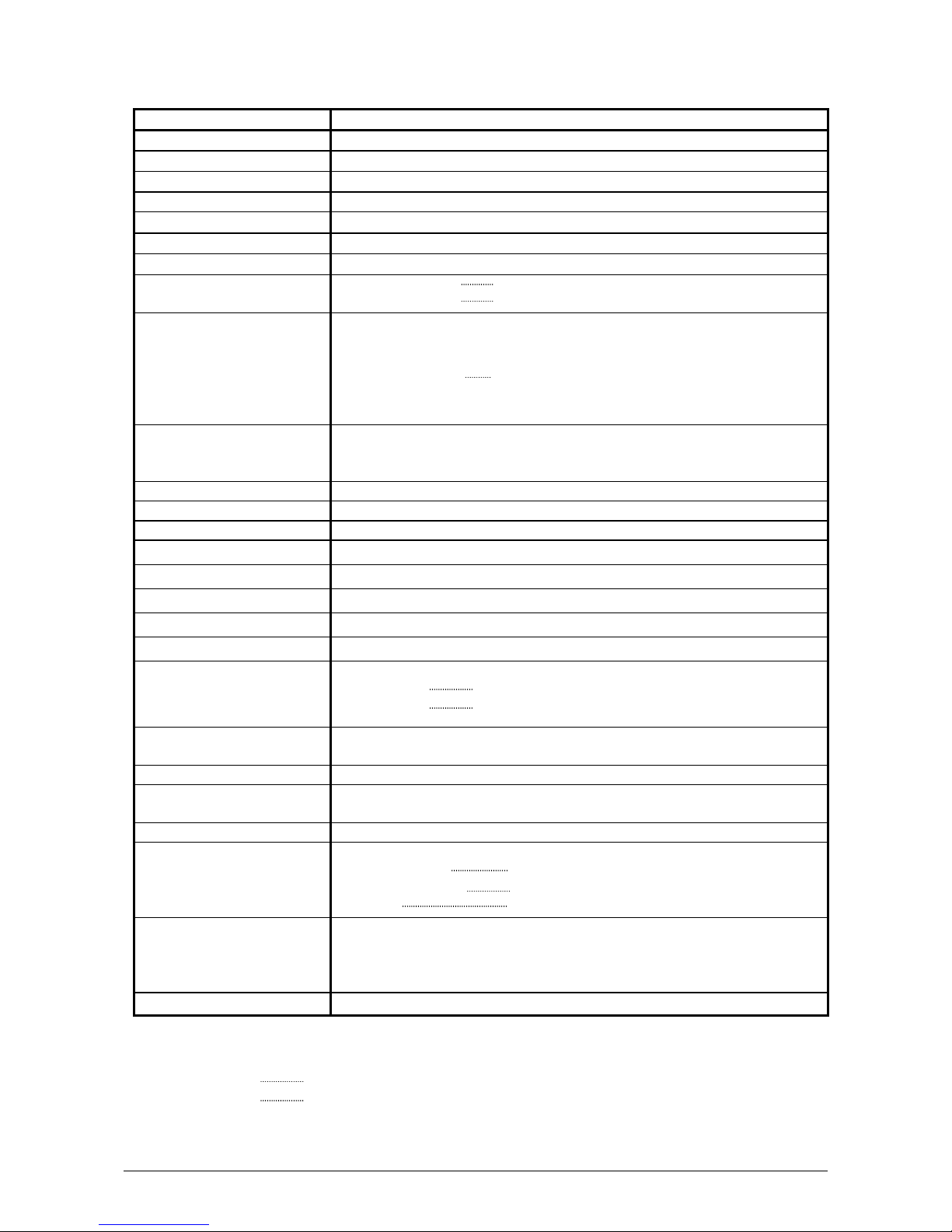
(1) In combination with an image Scanner
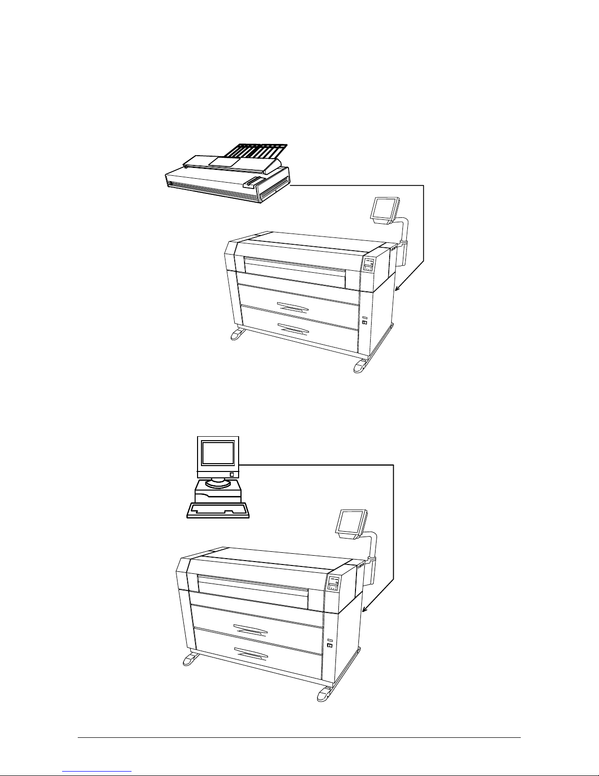
(2) In combination with a controller
Controller
Scanner
KIP 7000
KIP 7000
Part 1 Basic Functions 1-13
Page 20

(3) In combination with an image scanner and controller
Controller
Scanner
KIP 7000
Part 1 Basic Functions 1-14
Page 21

1. 8 Specifications for the Printing Paper
(
)
1. 8. 1 Available Print Size
Available print size is as follows.
Minimum Maximum
Width 11 inches (Roll Paper)
210mm
Length 8.5 inches 6 meters
NOTE
It is possible to print longer than 6 meters as an option.
You can choose either “24m” or “unlimited” as a maximum print length.
Call your service personnel if you would like to print over 6meters as the user can not
change this setting in the printer.
If you print longer than 6 meters, the image quality or the reliability of media feeding
is not guaranteed.
Cut Sheet paper
36 inches
Part 1 Basic Functions 1-15
Page 22

1. 8. 2 Media not to be used
Do not use the following kinds of printing paper. Doing so may damage the printer.
Excessively curled
Folded
Creased
Torn
Punched
Part 1 Basic Functions 1-16
Page 23

Pre-printed
Extremely slippery
Extremely sticky
Extremely thin and soft
OHP Film
CAUTION
Do not use the paper with staple, or do not use such conductive paper as aluminium foil and
carbon paper.
The above may result in a danger of fire.
NOTE
(1) Print image may become light if printed on a rough surface of the paper.
(2) Print image may become defective if the print paper has an excess curl.
(3) It will cause paper mis-feed, poor print image or creasing if you use a paper that does
not satisfy the specifications.
(4) Do not use a paper of which surface is very special, such as thermal paper, art paper,
aluminium foil, carbon paper and conductive paper.
(5) Vellum exposed to air over a long period tends to cause a poor printing.
We recommend you that you remove one round on the surface of the vellum from the
beginning by the Initial Cut Key on the User Interface (UI).
(6) Remove fully any adhesive from the roll that may remain due to tape placed by the media
supplier.
1. 8. 3 Maintaining the Media
Keep the paper in the custody taking care of the following matters.
1. Do not expose the paper to the direct sunlight.
2. Keep the paper away from high humidity. (It must be less than 70%)
3. Put the paper on a flat place, do not damage the media.
4. If you will keep paper which you has already been unpacked, put it into the plastic bag to
avoid humidity in the media.
Part 1 Basic Functions 1-17
Page 24

1. 8. 4 Environmental Condition - Correction
Take a necessary treatment according to the environmental condition as shown below.
Humidity(%)
Low
40%
70%
High
NOTE
(1) KIP 7000 is equipped with the Dehumidify Heater.
Using it in high humidity environment (65% or higher) is recommended.
Refer to [2. 6 Dehumidifying the Roll Media] on page 1-37.
(2) “Void of image” and “crease of paper” will occur in case of extremely high or low
humidity.
Possible problem Necessary treatment
“Void of image”, “crease of paper” and
other problems occurs when you print
with plain paper and vellum.
1. Install the humidifier in the room, and
humidify the room air.
2. Remove the media from the machine
right after the completion of print, and
keep it in a plastic bag.
“Void of image” occurs when you print
with vellum.
If you will not make print soon, remove
the vellum from the machine and keep it
in a plastic bag.
Remove the paper from the machine after
everyday use, and keep it in a plastic bag.
“Void of image” occurs when you print
with plain paper and vellum.
If you will not make print soon, remove
the media from the machine and keep it in
a plastic bag.
“Void of image”, “crease of paper” and
other problems occurs when you print
with plain paper and vellum.
1. Turn on the Dehumidify Heater.
2. Remove the media from the machine
right after the completion of print, and
keep it in a plastic bag.
Normal Print
Crease of paper
If the media is humidified ;
Normal Print
Loss of image
If the media is humidified ;
Part 1 Basic Functions 1-18
Page 25
NOTE
(3) Re-appearance of image (solid black image especially) may occur if you print with a
humidified film.
When film is installed under the high humidity environment (higher than 60%RH), we
also recommend that you turn on the Dehumidify Heater.
Normal print Re-appeared image
Part 1 Basic Functions 1-19
Page 26

Chapter 2 Basic Operations
2. 1 Turning on the KIP 7000
1) Plug the printer into an exclusive wall outlet.
WARNING
(1) Do not handle the Power Plug with wet hands, or you may receive an electrical shock.
(2) Ground the printer for safety.
(3) Do not plug the printer into a multi-wiring connector in which other devices are
plugged into. It may overheat the outlet and may result in a fire.
(4) The outlet must satisfy the following rated power condition.
220V - 240V plus 6% or minus 10%, 50/60Hz, 20A or higher
2) There is a Power Switch (A) on the right-front of KIP 7000.
Press “ON” to turn on the KIP 7000.
Press this side.
Part 1 Basic Functions 1-20
Page 27
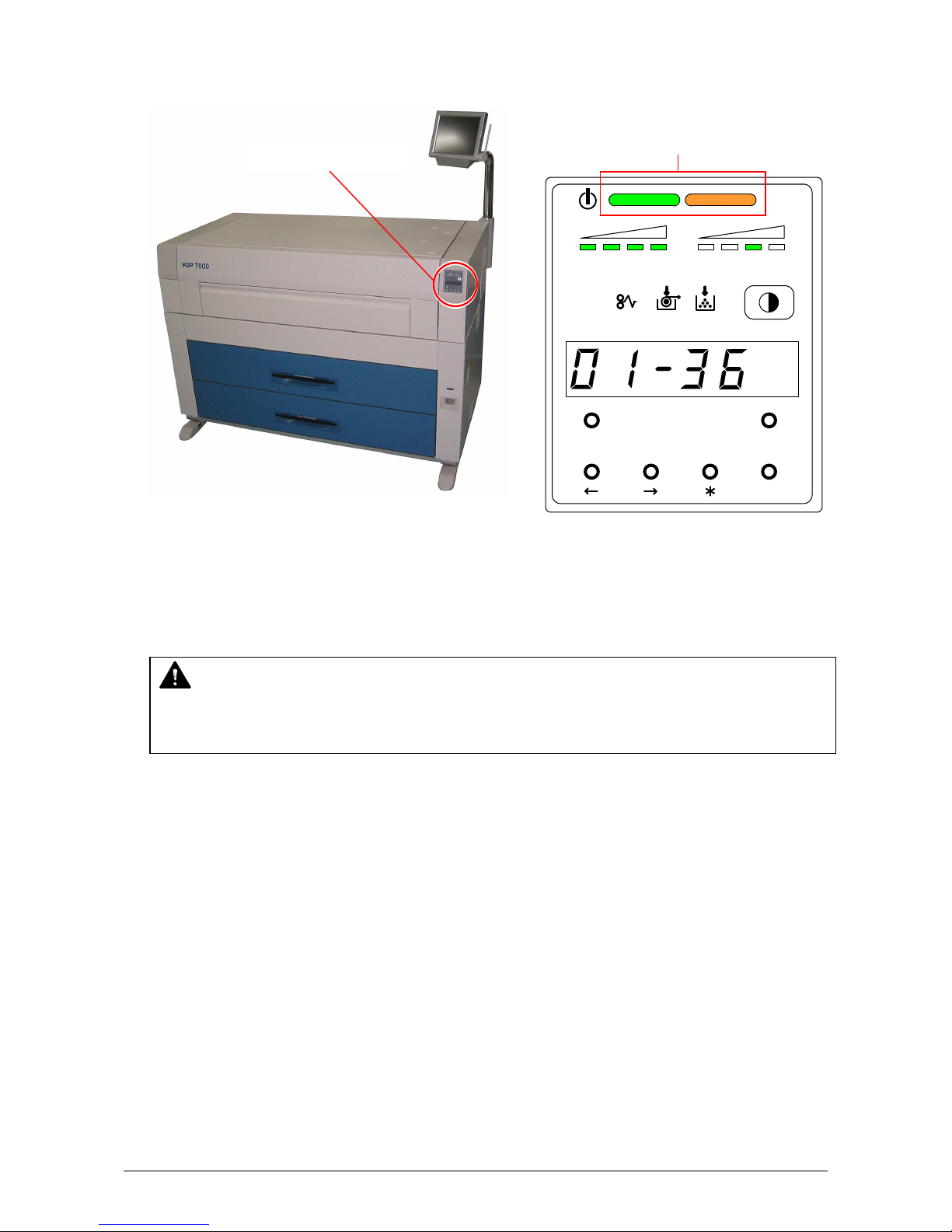
3) There is a Sub Display Panel on the right-front of the printer.
The Orange lamp of the Status Indicator lights when the printer is warming up.
Sub Display Panel
(Left : Green / Right : Orange)
Status Indicator
TONER REMAIN I MAGE DENSITY
job
MENU TEST
ENTER
4) When the Fuser has been enough heated up, the Green lamp of the Status Indicator lights and
the printer gets ready. (Orange lamp is OFF at that time.)
This may take up to 6 minutes from room temperature.
NOTE
It is impossible to make any prints when the Orange lamp is lighting.
Please wait until the Green lamp lights.
5) Print from your computer or copy from the scanner.
Part 1 Basic Functions 1-21
Page 28

2. 2 Turning off the KIP 7000
1) Press “OFF” on the Power Switch to turn off the KIP 7000.
CAUTION
The KIP 7000 and the User Interface (UI) look to be shut down when you turn off KIP 7000,
the IPS inside of KIP 7000 is still operating for approximately 2 minutes after Power Switch
operation.
Do not unplug the KIP 7000 before the IPS shutdown. Doing so may damage data or the
device.
Press this side.
Part 1 Basic Functions 1-22
Page 29
2. 3 Replacing the Roll Media
NOTE
The printer indicates a “Roll Empty Error” by
lighting up the Roll Empty Indicator on the
Sub Display Panel if the roll media currently used
is emptied during printing.
Install a new roll media using the following
directions.
Reference
We recommend you to install the Tracing
Paper Roll in the Roll 3 or the Roll 4.
Roll Empty Indicator
Front Rear
TONER REMAI N IMAGE DENSITY
job
MENU TEST
ENTER
Roll 1
Roll 3
Roll 2
Roll 4
Part 1 Basic Functions 1-23
Page 30
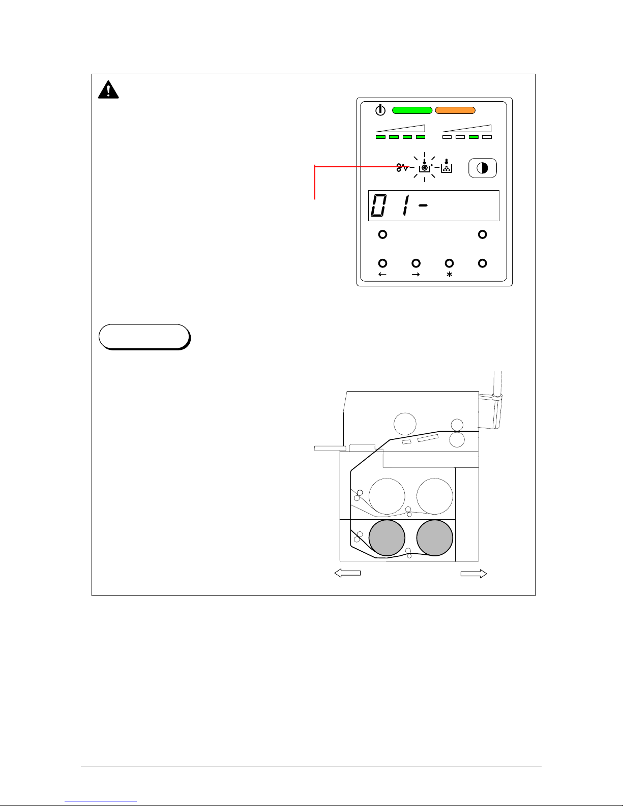
1) When the Roll Empty Indicator lights, check the emptied Roll Deck Number on the Display.
Example : Roll Deck Number is “01”.
This means the media in the
Roll 1 is empty.
TONER REMAIN IMAGE DENSIT Y
job
Roll Deck Number
MENU TEST
ENTER
2) Open the Roll Deck (A).
Rewind the remaining paper around its core
as shown arrow.
A
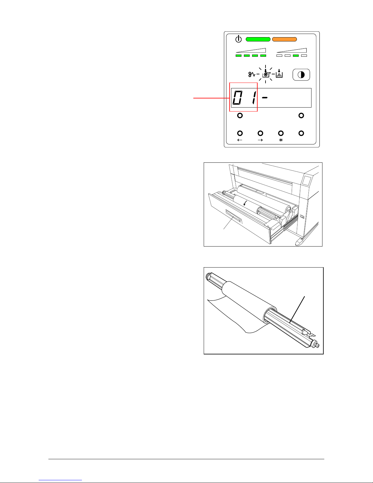
3) Remove the Roll Spool (B) from the Roll Deck.
B
Part 1 Basic Functions 1-24
Page 31
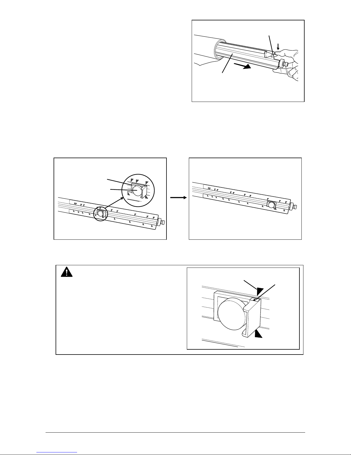
4) Pressing down Lever (C), pull out the Roll
Spool (B) from the core of the roll.
C
B
5) Loosen the Thumb Screw (D), and slide the Stopper (E) according to the width of the new roll
of media.
Tighten the Thumb Screw to fix the Stopper at the corresponding size mark.
E
D
NOTE
Align the top of triangle (F) of stopper and
the size mark (G).
G
F
A
0
Part 1 Basic Functions 1-25
Page 32
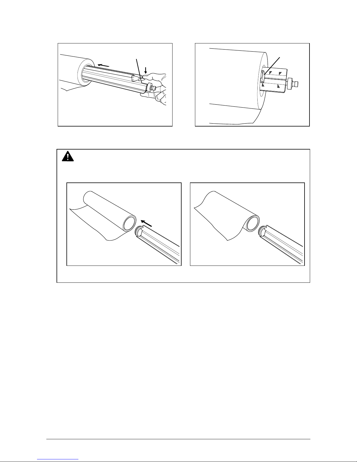
6) Pressing down the Lever (C), insert the Roll Spool fully into the core until the Stopper (E)
touches the roll media.
Then, release the Lever (C) to “catch” the roll media with the Roll Spool.
C
E
3
4
"
3
6
"
A
0
3
6
"
NOTE
Be careful of the winding direction of roll media.
Good
No good
Part 1 Basic Functions 1-26
Page 33

7) In case you load Roll 1 or Roll 3;
Roll 1
Roll 2
Roll 3
Roll 4
Front
Rear
7-1) Put back the Roll Spool into the Roll Deck.
(Gear side is on the left and Lever side is on the right.)
Gear side
NOTE
When you put back the Roll Spool into the Roll Deck, make sure to fit the collar of the right
side of the Roll Spool into the proper position.
No Good Good
(The collar of the Roll Spool is out of (The collar is set in the proper position.)
the proper position.)
Part 1 Basic Functions 1-27
Page 34
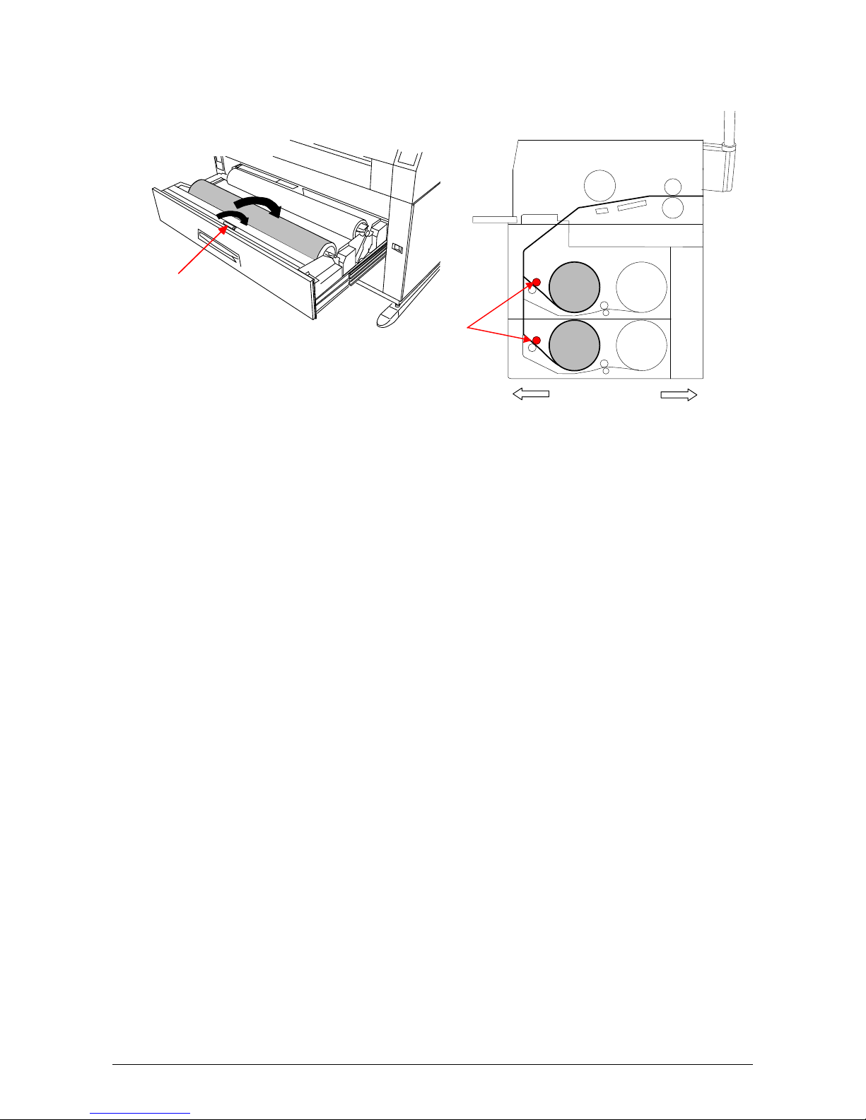
7-2) Rotate the green knob as shown arrow and feed the leading edge of the media between
Feeding Rollers.
Knob
Roll 1 Roll 2
Knob
Roll 3 Roll 4
Front Rear
7-3) Close the Roll Deck.
7-4) Press the Initial Cut Key on the User Interface (UI) to cut the leading edge.
Remove the paper portion.
Part 1 Basic Functions 1-28
Page 35

8) In case you load Roll 2 or Roll 4;
Roll 1 Roll 2
Front Rear
Roll 3 Roll 4
8-1) Put the Roll Spool onto the Operator aid Arm. Arm
(Gear side is on the left and Lever side
is on the right.)
Part 1 Basic Functions 1-29
Page 36

8-2) Move the right one of Operator aid Arms
backward and then move the left one similarly.
The Roll Spool is set in the proper position
Hereby.
(Do not move both Operator aid Arms at the
same time.)
NOTE
1. “Operator aid Arm” was prepared to help the operator when you load the roll paper on the
deeper Deck. Follow the above procedure for your safety.
2. When you put back the Roll Spool into the Roll Deck, make sure to fit the collar of the
right side of the Roll Spool into the proper position.
No Good Good
(The collar of the Roll Spool is out of (The collar is set in the proper position.)
the proper position.)
2
1
Part 1 Basic Functions 1-30
Page 37

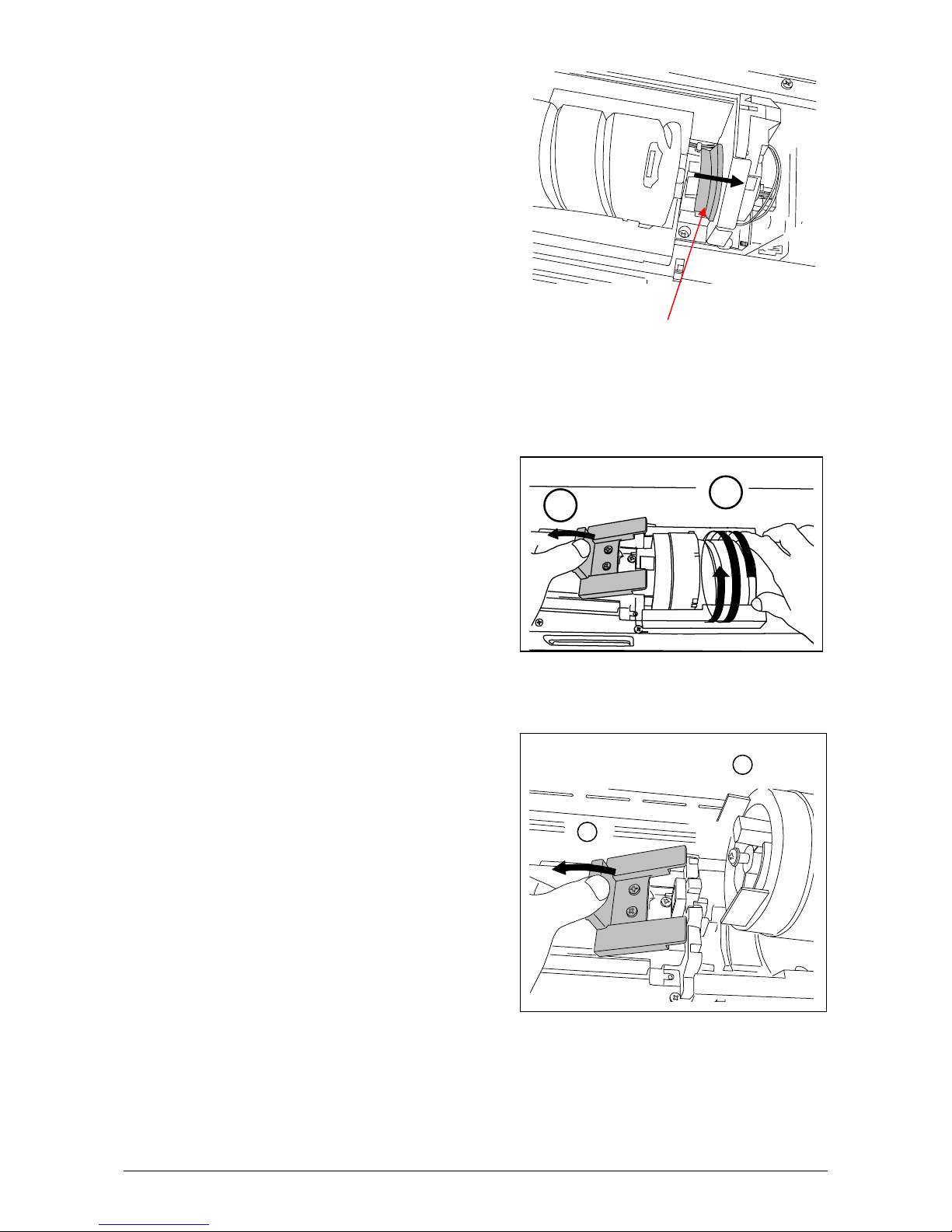
8-3) Rotate the green knob as shown arrow and feed the leading edge of the media between
Feeding Rollers.
Knob
Roll 1
Roll 2
Roll 3
Roll 4
Front Rear
Knob
NOTE
When you load the media, rotate the Paper Feeding Roller Knob.
Do not feed the media so much because the leading edge may come out from the slit.
If you close the Roll Deck while the leading edge is out of the slit, the roll media is folded
and printing becomes not available.
8-4) Close the Roll Deck.
8-5) Press the Initial Cut Key on the User Interface (UI) to cut the leading edge.
Remove the paper portion.
Part 1 Basic Functions 1-31
Page 38

2. 4 Replacing the Toner Cartridge
WARNING
There is combustible powder in the toner cartridge.
Do not burn up the used toner cartridge.
1) Open the Manual Table.
2) Pull out the Upper Frame Unit to your side
with holding both handles.
NOTE
The printer will indicate a “Toner Low Error” by Toner Low Indicator
lighting the Toner Low Indicator on the Sub
Display Panel.
Replace the Toner Cartridge with the new
cartridge using the following procedure:
(Please use the KIP Toner Cartridge.)
TONER REMAI N IMAGE DENSITY
job
MENU TEST
Handle
Manual Table
ENTER
Part 1 Basic Functions 1-32
Page 39
3) Push the Joint rightward to release the Toner Cartridge.
(The joint is latched.)
Joint
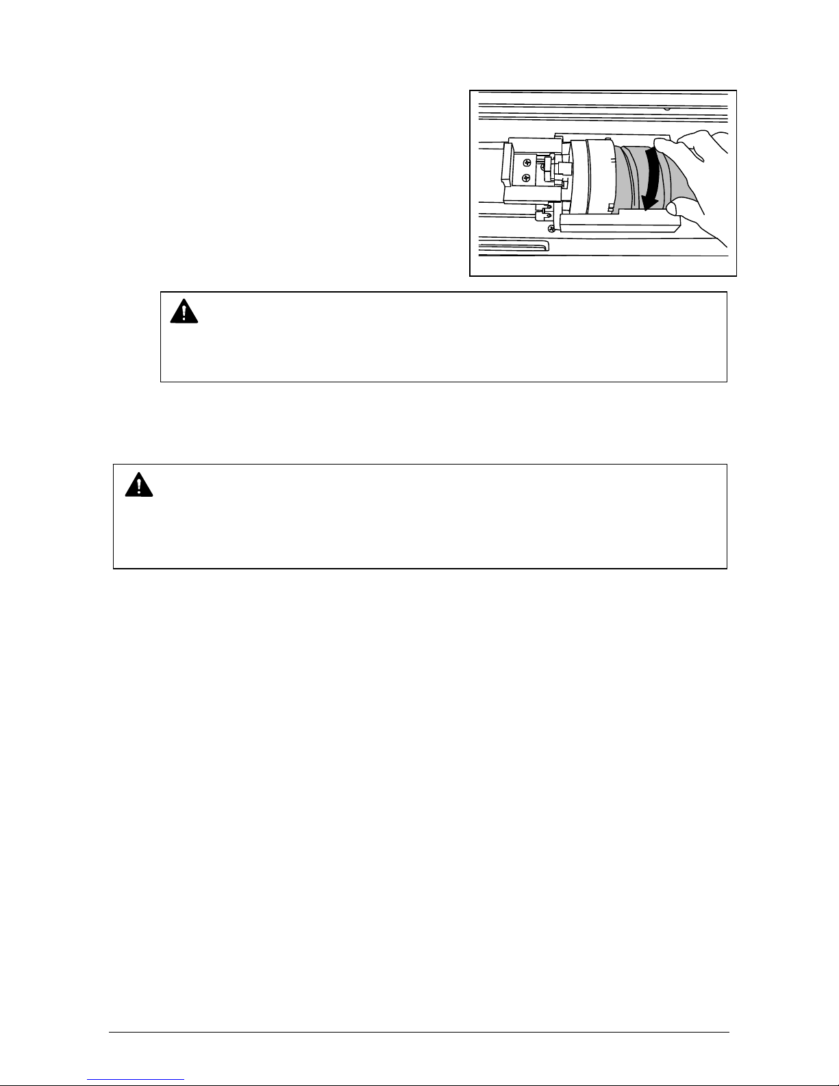
4) Press and hold the Lever to the left, and then rotate the Toner Cartridge (not the Cap of
Cartridge) as shown arrow in order to close the opening.
Approximately 2 rotations will be enough to close the opening, but rotate the Toner Cartridge
until it stops completely.
1
2
5) Keep pressing the Lever to the left, and lift up the Toner Cartridge.
2
1
Part 1 Basic Functions 1-33
Page 40

6) Shake a new Toner Cartridge several times right and left to make the toner smooth.
7) Insert the far left Collar of the Toner Cartridge into the slot firmly with pressing the Lever to
the left.
(Please direct the opening of the Toner Cartridge downward at this time.)
2
1
3
8) Pull the Toner Cartridge rightward a little, and insert the swelling in the slot.
1
2
Part 1 Basic Functions 1-34
Page 41
9) Rotate the Toner Cartridge to the arrow direction at least 90 degrees.
(The new Toner Cartridge is closed firmly so as not to lose the toner during the transportation)
NOTE
Even if the Joint is not fit to the Toner Cartridge, when you turn on the power, it is
automatically fit properly.
10) Push in the Upper Frame Unit firmly.
NOTE
If your hand or your clothing are soiled by toner, dust the toner.
If it is unable to dust it, wash the clothing with the cold water.
(Do not use the hot water at this time because the toner will soak into fiber.)
Part 1 Basic Functions 1-35
Page 42

2. 5 Setting the Cut Sheet Paper
1) Open the Manual Table.
2) There are several kinds of size mark on the Manual Table.
Put the cut sheet paper on the table along with the concerning size mark, and then insert it into
the Bypass Feeder along with the size mark.
NOTE
In case that the Cut Sheet Paper is inserted manually, its size and media are not indicated
on the Sub Display Panel.
Manual Table
Size Mark
Part 1 Basic Functions 1-36
Page 43
2. 6 Dehumidifying the Roll Media
If the roll paper is extremely humid, it may cause poor prints.
You will experience most likely “creasing” and “voids”.
NOTE
Re-appearance of image (especially solid black image) may occur if you print with a
humidified film.
When film is installed under the high humidity environment (higher than 60%RH), we also
recommend that you turn on the Dehumidify Heater.
Turn on the Dehumidify Heater if the room air has too much humidity (65% or higher) to prevent
the above kinds of print defect.
You may be able to fix the above kinds of problem.
Normal print Re-appeared image
Normal Print
Normal Print
Creasing
If the media is humidified ;
Voids
If the media is humidified ;
Part 1 Basic Functions 1-37
Page 44

NOTE
(1) There are several dehumidifying settings which can be set by the service personnel.
When these setting determine, the dehumidifier functions.
With any setting, the printer must be plugged in and the switch noted above must be
in the “ON” position.
Call your service personnel if you would like to change the switch setting.
Note that the user can not change the setting.
(2) To achieve the best image quality, we recommend that you use media that is unpacked
from the manufacture right before installing it into the printer.
If media is unpacked long before installation, poor image quality may occur.
“Dehumidify Heater Switch” is located on the left-rear side of the machine.
Press “H” to turn on the Dehumidify Heater.
Dehumidify Heater Switch
Part 1 Basic Functions 1-38
Page 45

Chapter 3 Operations for Useful Functions
3. 1 Changing the Density Level
If you would like to make the image darker or lighter, you will change the density level on the
scanner or controller.
After specifying the density level on the scanner or controller, it is also possible to compensate the
image density on the printer, if needed.
Image Density Indicator
Level 4 (Darkest)
Density Selection Key
There are 4 kinds of levels. (The default setting is Level 3).
Levels are changed by pressing the Density Selection Key.
(The image density gets darker by selecting the bigger level number.)
Level 1 Level 2 Level 3 Level 4
darker darker darker
TONER REMAI N IMAGE DENSITY
Level 1 (Lightest)
job
MENU TEST
ENTER
Part 1 Basic Functions 1-39
Page 46

3. 2 User Mode
To enter the User Mode
Press and hold the [Menu] key for more than 3 seconds.
Then User Mode Number and its contents are shown on the Display.
User Mode Number Contents
You can change the User Mode by pressing [ ] or [ ] key,.
U0. (Reserved) Page 1-41
U1. Image Enhancement Setting Mode Page 1-42
U2. Auto Power Off Timer Setting Mode Page 1-44
U3. Auto Power Off Setting Mode Page 1-45
U4. Cold Sleep Timer Setting Mode Page 1-46
U5. Cold Sleep Setting Mode Page 1-47
U6. Warm Sleep Timer Setting Mode Page 1-48
U7. Warm Sleep Setting Mode Page 1-49
U8. (Reserved) Page 1-50
U9. L/L Environment Setting Mode Page 1-51
UA. H/H Environment Setting Mode Page 1-53
Ub. High Coverage Setting Mode Page 1-55
UC. (Reserved) Page 1-56
Ud. (Reserved) Page 1-57
To exit from the User Mode
Press [Menu] key again.
TONER REMAI N IMAGE DENSITY
job
MENU TEST
ENTER
Part 1 Basic Functions 1-40
Page 47

3. 2. 1 User Mode 0: (Reserved)
Keep this mode always “oFF”. (Do not change this setting.)
Part 1 Basic Functions 1-41
Page 48

3. 2. 2 User Mode 1: Image Enhancement Setting Mode
A weak image can be emphasized by such functions as the Dot Enhancement Level and the
Smoothing Function so that it looks clearer.
Reference
(1) An isolated dot image can be emphasized by the Dot Enhance Level.
(Dot Enhance Level does not affect the compacted dots.)
Isolated dots are emphasized.
(2) A diagonal line tends to look weaker then vertical one or horizontal one.
The Smoothing Function emphasizes the diagonal line so that it becomes as clear as
vertical one or horizontal one.
Diagonal lines are emphasized
Part 1 Basic Functions 1-42
Page 49

1) Select User Mode 1 “U1.” by pressing [ ] or [ ] key.
g
TONER REMAIN IMAGE DENSITY
job
MENU TEST
Applied to the prints
from controller
ENTER
The setting value consists of 2 digits.
The left value is not used.
The right one is applied to the print from controller.
The following list shows the selectable setting value and their contents.
Setting Value Contents
0 Dot Enhancement Level 0 : None With
1 Dot Enhancement Level 1 : Weak
the Smoothing Function
2 Dot Enhancement Level 2 : Medium
3 Dot Enhancement Level 3 : Strong
4 Dot Enhancement Level 0 : None Without
5 Dot Enhancement Level 1 : Weak
the Smoothing Function
6 Dot Enhancement Level 2 : Medium
7 Dot Enhancement Level 3 : Strong
2) Press [Enter] key to change the Image Enhancement setting for the print from controller.
TONER REMAIN IMAGE DENSITY
job
Image Enhancement setting
for the print from controller
MENU TEST
ENTER
Press this key to change
of settin
for the print
Part 1 Basic Functions 1-43
Page 50

3. 2. 3 User Mode 2: Auto Power Off Timer Setting Mode
This mode allows you to set Auto Power Off Timer.
Reference
The Auto Power Off is the function that the Power Switch turns OFF automatically if the
printer makes no printing (copying) operation for the time decided in the User Mode 2.
(As for turning on the printer, press “ON” of the Power Switch.)
1) Select User Mode 2 “U2.” by pressing [ ] or [ ] key.
The current setting timer is displayed.
2) Press [ * ] (increment) or [Enter] (decrement) key to change the setting value.
Timer is adjustable from 5 to 240 minutes (1 min. step).
NOTE
To make the Auto Power Off work, it is necessary to make this function ON in the Auto
Power Off Setting Mode (User Mode 3). (Refer to page 1-45)
TONER REMAI N IMAGE DENSITY
job
MENU TEST
ENTER
TONER REMAI N IMAGE DENSITY
job
MENU TEST
ENTER
Part 1 Basic Functions 1-44
Page 51

3. 2. 4 User Mode 3: Auto Power Off Setting Mode
It is possible to select whether or not the Auto Power Off works.
Reference
The Auto Power Off is the function that the Power Switch turns OFF automatically if the
printer makes no printing (copying) operation for the time decided in the User Mode 2.
(As for turning on the printer, press “ON” of the Power Switch.)
1) Select User Mode 3 “U3.” by pressing [ ] or [ ] key.
U 3. o n : Auto Power Off function works.
U 3. o F F : Auto Power Off function does not work.
2) Select either “on” or “oFF” according to the necessity by pressing [ENTER] key.
TONER R EMAIN IMAGE DENSITY
job
MENU TEST
ENTER
TONER REMAI N IMAGE DENSITY
job
MENU TEST
ENTER
Part 1 Basic Functions 1-45
Page 52

3. 2. 5 User Mode 4: Cold Sleep Timer Setting Mode
Do not change this setting.
It is possible to change the timer for the Cold Sleep function on the User Interface (UI).
Reference
1. The purpose of Cold Sleep Mode is to reduce the power consumption by shutting off to
supply the power to the heater unit.
It can save more power than Warm Sleep Mode.
The temperature of the heater unit is about 150 degrees Centigrade when the KIP 7000
is ready. But if no print job or copy job is sent for a long time, it is best for saving the
power to stop supplying the power to the heater unit completely.
The Cold Sleep Mode will be cancelled automatically if only you send a print job or a copy
job from the outer device.
However, please understand it takes a little long time to recover from the Cold Sleep Mode
because it is necessary to raise the temperature again up to about 150 degrees
Centigrade.
(Print does not start until the KIP 7000 gets ready.)
2. When both the Cold Sleep Function and the Warm Sleep Function are effective, their
functions work as follows; (Both timers start simultaneously.)
As for the Warm Sleep Function, refer to page 1-46, 1-47.
<Example 1>
In case that the Warm Sleep Timer is 15 minutes and the Cold Sleep Timer is
30 minutes, the printer will go into the warm sleep mode in 15 minutes after printing.
And it will also go into the Cold Sleep Mode in 15 minutes after the printer goes into
the Warm Sleep Mode.
<Example 2>
In case that the Warm Sleep Timer is 30 minutes and the Cold Sleep Timer is
15 minutes, the printer will go into the Cold Sleep Mode in 15 minutes after printing.
In this case, the Warm Sleep Function does not work.
Part 1 Basic Functions 1-46
Page 53

3. 2. 6 User Mode 5: Cold Sleep Setting Mode
Keep this mode always “oFF”. (Do not change this setting.)
It is possible to select whether the Cold Sleep function works or not on the User Interface (UI).
Reference
The purpose of Cold Sleep Mode is to reduce the power consumption by shutting off to
supply the power to the heater unit.
It can save more power than Warm Sleep Mode.
The temperature of the heater unit is about 150 degrees Centigrade when the KIP 7000
is ready. But if no print job or copy job is sent for a long time, it is best for saving the power to
stop supplying the power to the heater unit completely.
The Cold Sleep Mode will be cancelled automatically if only you send a print job or a copy
job from the outer device.
However, please understand it takes a little long time to recover from the Cold Sleep Mode
because it is necessary to raise the temperature again up to about 150 degrees Centigrade.
(Print does not start until the KIP 7000 gets ready.)
Part 1 Basic Functions 1-47
Page 54

3. 2. 7 User Mode 6: Warm Sleep Timer Setting Mode
Do not change this setting.
It is possible to change the timer for the Warm Sleep function on the User Interface (UI).
Reference
1. The purpose of Warm Sleep Mode is to reduce the power consumption by falling down
the temperature of heater some degrees.
The temperature of the heater unit is about 150 degrees Centigrade when the KIP 7000
is ready. But if no print job or copy job is sent for a long time, it is better for saving
the power to fall down the temperature of heater.
(Temperature is kept about 120 degrees Centigrade.)
The Warm Sleep Mode will be cancelled automatically if only you send a print job or
a copy job from the outer device.
However, please understand it takes some minutes to recover from the Warm Sleep Mode
because it is necessary to raise the temperature again up to about 150 degrees
Centigrade.
(Print does not start until the KIP 7000 gets ready.)
2. When both the Cold Sleep Function and the Warm Sleep Function are effective, their
functions work as follows; (Both timers start simultaneously.)
As for the Cold Sleep Function, refer to page 1-48, 1-49.
<Example 1>
In case that the Warm Sleep Timer is 15 minutes and the Cold Sleep Timer is 30 minutes,
the printer will go into the warm sleep mode in 15 minutes after printing.
And it will also go into the Cold Sleep Mode in 15 minutes after the printer goes into
the Warm Sleep Mode.
<Example 2>
In case that the Warm Sleep Timer is 30 minutes and the Cold Sleep Timer is 15 minutes,
the printer will go into the Cold Sleep Mode in 15 minutes after printing.
In this case, the Warm Sleep Function does not work.
Part 1 Basic Functions 1-48
Page 55

3. 2. 8 User Mode 7: Warm Sleep Setting Mode
Keep this mode always “oFF”. (Do not change this setting.)
It is possible to select whether the Warm Sleep function works or not on the User Interface (UI).
Reference
The purpose of Warm Sleep Mode is to reduce the power consumption by falling down the
temperature of heater some degrees.
The temperature of the heater unit is about 150 degrees Centigrade when the KIP 7000
is ready. But if no print job or copy job is sent for a long time, it is better for saving the power
to fall down the temperature of heater. (Temperature is kept about 120 degrees Centigrade.)
The Warm Sleep Mode will be cancelled automatically if only you send a print job or a copy
job from the outer device.
However, please understand it takes some minutes to recover from the Warm Sleep Mode
because it is necessary to raise the temperature again up to about 150 degrees Centigrade.
(Print does not start until the KIP 7000 gets ready.)
Part 1 Basic Functions 1-49
Page 56

3. 2. 9 User Mode 8: (Reserved)
Keep this mode always “oFF”. (Do not change this setting.)
Part 1 Basic Functions 1-50
Page 57

3. 2.10 User Mode 9: L/L Environment Setting Mode
It is possible to select whether or not the L/L Environment Setting Mode should work.
Reference
“Crease of paper” or “Defective fusing” may occur when a large paper (wider than 30”) is
used in the low temperature and low humidity environment (It is called L/L Environment).
This is caused by the fall of temperature of the Heater Unit (hot part inside of the Exit Cover).
If the L/L Environment Setting Mode works, the interval of prints becomes longer than usual
to recover the temperature. (Print productivity is reduced to about 3 sheets / minute although
it is about 7 sheets / minute usually.)
The L/L Environment Mode works not always but only in some specific case, for example
when the remaining volume of roll is very small or when a tracing paper is used.
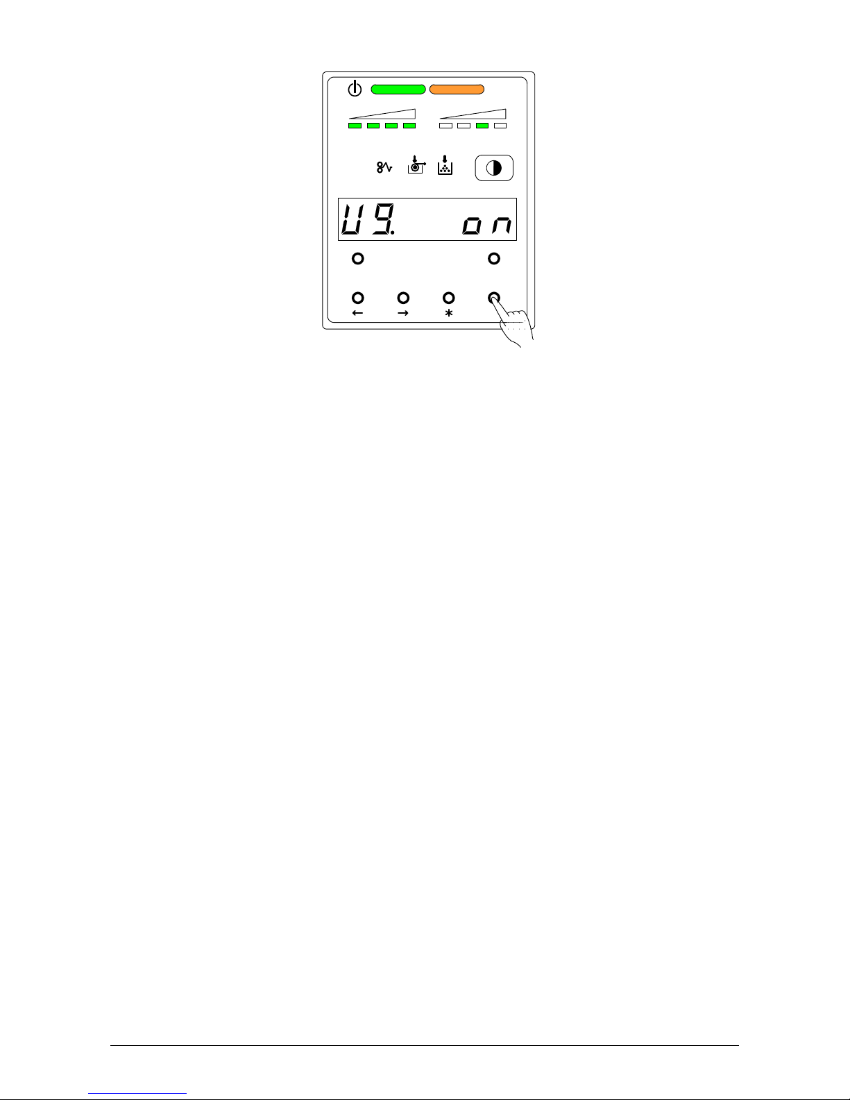
1) Select User Mode 9 “U9.” by pressing [ ] or [ ] key.
U 9. o n : Low Temperature / Low Humidity Environment Setting works.
U 9. o F F : Low Temperature / Low Humidity Environment Setting does not work.
(Normal operation)
TONER R EMAIN IMAGE DENSITY
job
MENU TEST
ENTER
Part 1 Basic Functions 1-51
Page 58
2) Select either “on” or “oFF” according to the necessity by pressing [ENTER] key.
TONER REMAI N IMAGE DENSITY
job
MENU TEST
ENTER
Part 1 Basic Functions 1-52
Page 59
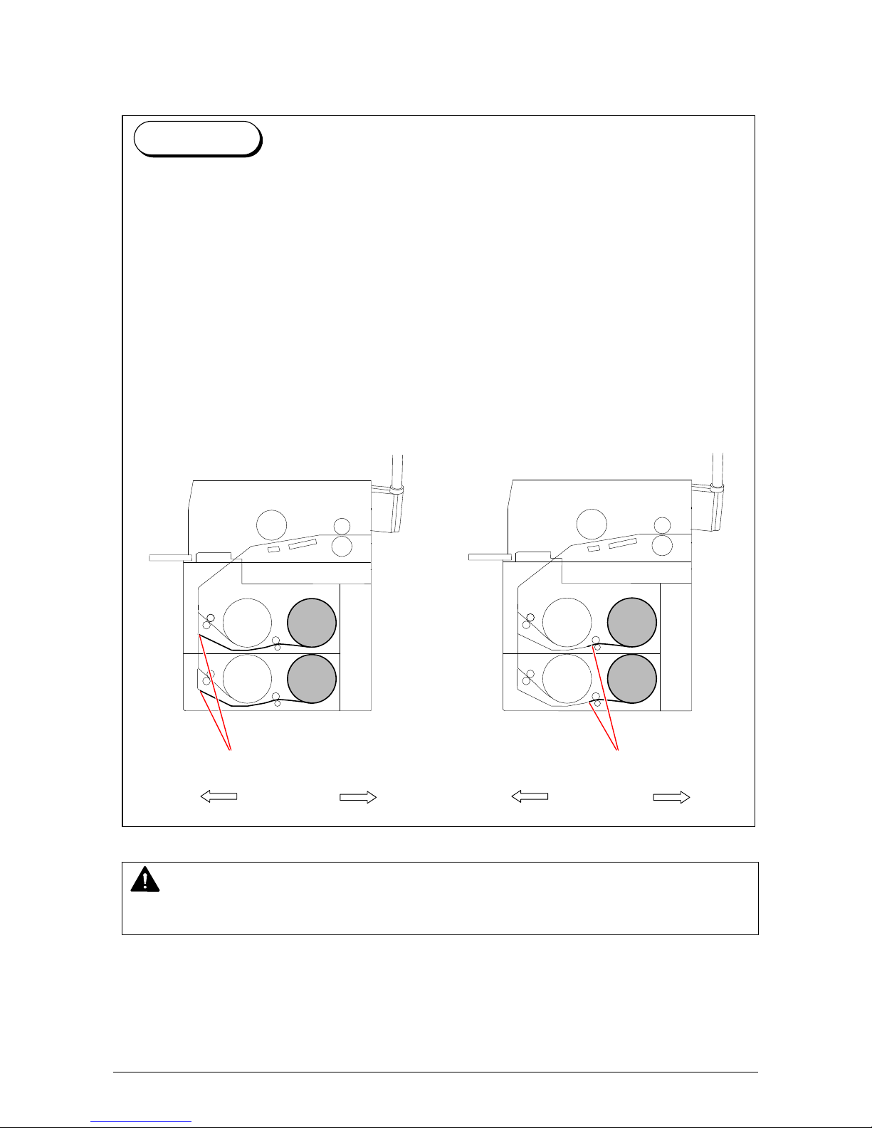
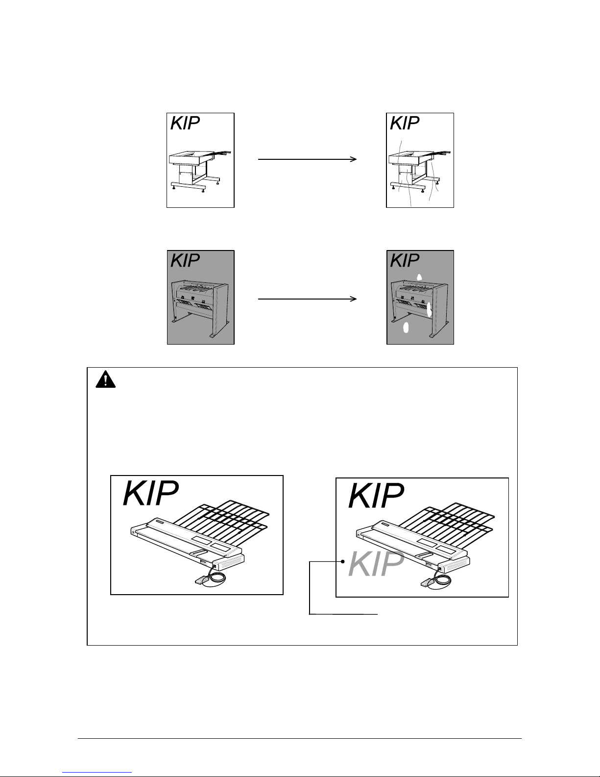
3. 2.11 User Mode A: H/H Environment Setting Mode
It is possible to select whether or not the H/H Environment Setting Mode should work.
Reference
“Crease of paper” or “Foggy background” may occur when a large paper (wider than 30”) is
installed to the Roll 2 or Roll 4 in the high temperature and high humidity
environment (It is called H/H Environment).
The reason for these problems is that the leading part of paper gets humidified as very long
range of paper is exposed to the humid air because of its waiting position.
If the H/H Environment Setting Mode works, the leading edge is waited at the nearer position
to the roll so that the leading part should not get humidified.
You can avoid the above kinds of problem as a result.
Please note that it takes about 1.5 seconds longer time than usual until the printer completes
the 1st sheet of prints.
<Normal Operation> <H/H Environment Setting works>
Front Rear Front Rear
Waiting position Waiting position
NOTE
In case this mode is selected under the normal environment, foggy image might be happened.
Roll 1 Roll 2
Roll 3 Roll 4
Roll 1 Roll 2
Roll 3 Roll 4
Part 1 Basic Functions 1-53
Page 60

1) Select User Mode A “UA.” by pressing [ ] or [ ] key.
TONER R EMAIN IMAGE DENSITY
job
MENU TEST
ENTER
U A. o n : H/H Environment Setting works.
U A. o F F : H/H Environment Setting does not work. (Normal operation)
2) Select either “on” or “oFF” according to the necessity by pressing [ENTER] key.
TONER REMAI N IMAGE DENSITY
job
MENU TEST
ENTER
Part 1 Basic Functions 1-54
Page 61

3. 2.12 User Mode b: High Coverage Setting Mode
It is possible to select whether or not the High Coverage Setting Mode should work.
High Coverage Setting Mode will be effective if the image density looks lighter when you print
some image pattern which consists of many data.
Please make it work in such case.
1) Select User Mode b “Ub.” by pressing [ ] or [ ] key.
U b. o n : High Coverage Setting Mode works.
U b. o F F : High Coverage Setting Mode does not work. (Normal operation)
2) Select either “on” or “oFF” according to the necessity by pressing [ENTER] key.
TONER R EMAIN IMAGE DENSITY
job
MENU TEST
ENTER
TONER REMAI N IMAGE DENSITY
job
MENU TEST
ENTER
Part 1 Basic Functions 1-55
Page 62

3. 2.13 User Mode C: (Reserved)
Keep this mode always “oFF”. (Do not change this setting.)
Part 1 Basic Functions 1-56
Page 63

3. 2.14 User Mode d: (Reserved)
Keep this mode always “oFF”. (Do not change this setting.)
Part 1 Basic Functions 1-57
Page 64

Chapter 4 Error Indications and Treatments
4. 1 Paper Mis-feed Errors
If the Paper Mis-feed occurs, the Paper Mis-feed Indicator on the Sub Display Panel lights to
inform you of the error.
The Sub Display Panel also indicates the Paper Mis-feed Code ( J-XX ) to let you know where the
paper is mis-fed.
Example : J-01 (Paper Mis-feed in the Roll 1)
Paper Mis-feed Indicator
Paper Mis-feed Code
Please check where the Paper Mis-feed has occurred referring to the following diagram.
(Greater detail on each code are on the following pages.)
J-11
J-05
J-10
J-01
Roll 1 Roll 2
J-02
J-03
J-04
Roll 3 Roll 4
Front
TONER REMAIN IMAGE DENSITY
job
MENU TEST
J-12
J-13、J-14
ENTER
J-21、J-22
Outer Device
(Auto Stacker,
Folder, etc.)
Rear
Part 1 Basic Functions 1-58
Page 65

NOTE
(1) Carefully remove the mis-fed paper so as not to harm your hand by cutting with the
paper edge.
(2) Take off a necklace, a bracelet and a wristwatch before removing the mis-fed paper.
You may be burnt or get an electric shock if such a metal accessory touches the inside
of the printer.
(3) The toner image is not fixed firmly if the paper did not reach the Fuser Section.
Therefore be careful not to soil your clothing with the toner when you remove the mis-fed
paper.
Please dust the toner if your clothing is soiled.
If it is unable to dust it, wash the clothing with the cold water.
(Do not use the hot water at this time because the toner will soak into fiber.)
(4) The toner image is not fixed firmly if the paper did not reach the Fuser Section.
Therefore be careful that the toner should not get into your eye, or be careful not to
inhale the toner.
(Please wash out with water if it gets into your eye or mouth.)
Part 1 Basic Functions 1-59
Page 66
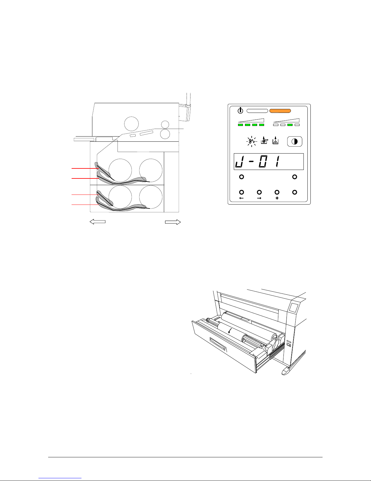
4. 1. 1 Paper Mis-feed in the Roll Deck Section (J-01, J-02, J-03, J-04)
When the Paper Mis-feed occurs in the Roll Deck, the Sub Display Panel indicates any of “J-01”,
“J-02”, “J-03” and “J-04”.
J-01 : In the Roll 1
J-02 : In the Roll 2
J-03 : In the Roll 3
J-04 : In the Roll 4
J-01
J-02
Roll 1
Roll 2
J-03
J-04
Front Rear
Roll 3
Roll 4
Clear the Paper Mis-feed using the following procedure:
1) Open the Roll Deck in issue. And then rewind the roll onto the media core.
TONER REMAI N IMAGE DENSITY
job
MENU TEST
ENTER
Part 1 Basic Functions 1-60
Page 67
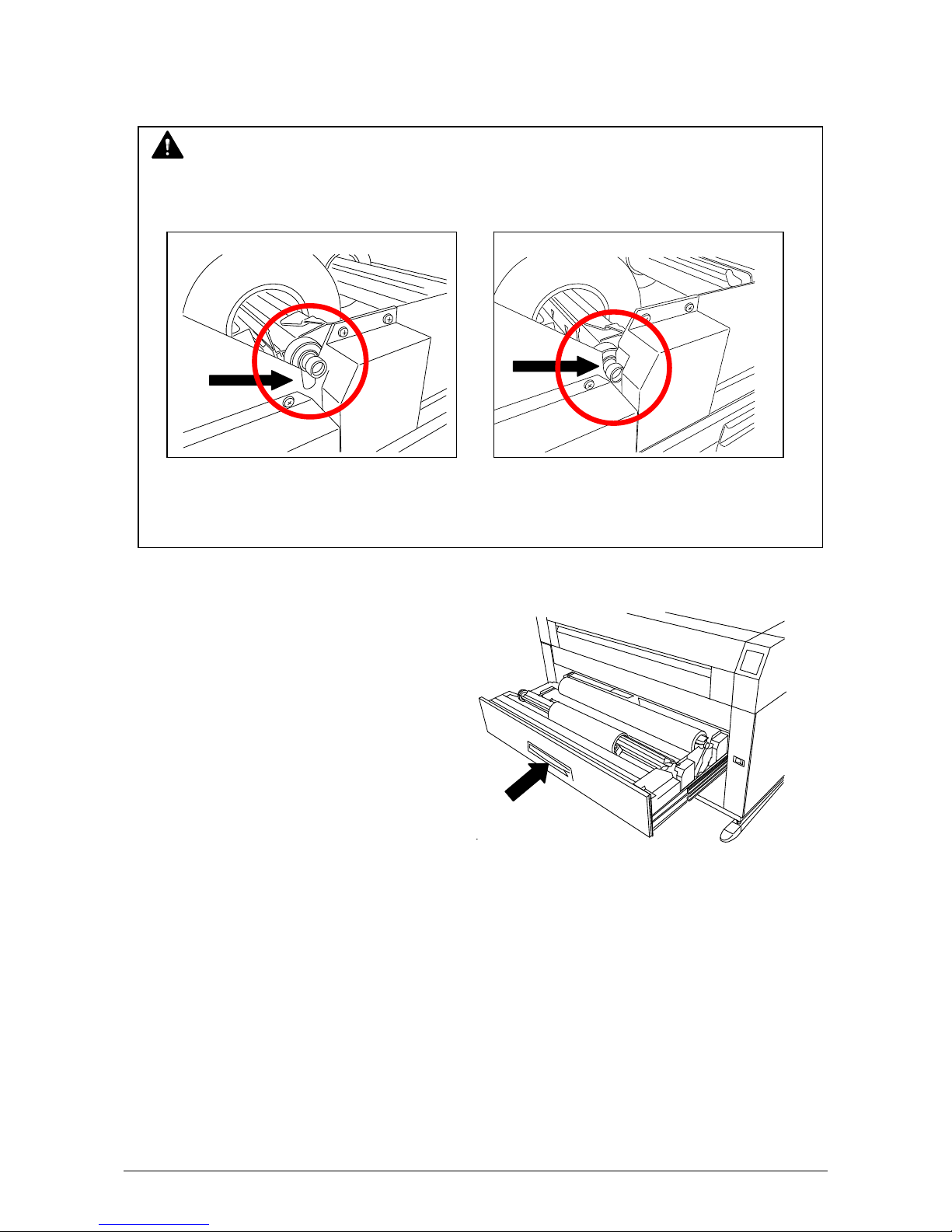
2) If the leading edge of the media is torn or folded, cut it off.
3) Set the roll media correctly.
NOTE
When you put back the Roll Spool into the Roll Deck, make sure to fit the collar of the right
side of the Roll Spool into the proper position.
No Good Good
(The collar of the Roll Spool is out of (The collar is set in the proper position.)
the proper position.)
4) Close the Roll Deck.
Part 1 Basic Functions 1-61
Page 68

4. 1. 2 Paper Mis-feed in the Manual Feeder Section (J-05)
When the paper mis-feed occurs in the Manual Feeder, the Sub Display Panel indicates “J-05”.
J-05
Roll 1
Roll 2
Front Rear
Roll 3
Roll 4
Clear the Paper Mis-feed using the following procedure:
1) Pull out the mis-fed paper from the Manual Feeder, and if the leading edge of the paper is torn
or folded, replace with the new one.
TONER REMAI N I MAGE DENSITY
job
MENU TEST
ENTER
Part 1 Basic Functions 1-62
Page 69

4. 1. 3 Paper Mis-feed in the Paper Feed Section (J-10, J-11, J-12)
When the Paper Mis-feed occurs in the Paper Feed Section, Sub Display Panel indicates any of
“J-10”, “J-11” and “J-12” according to the position of mis-feed.
J-10 : Front area
J-11 : Middle area
J-12 : Rear area
J-10 J-11 J-12
Roll 1
Roll 2
Roll 3
Roll 4
Front
Rear
TONER RE MAIN IMAGE DENSITY
job
MENU TEST
ENTER
TONER REMAI N IMAGE DENSITY
job
MENU TEST
ENTER
TONER REMAI N IMAGE DENSITY
job
MENU TEST
ENTER
Part 1 Basic Functions 1-63
Page 70
Clear the Paper Mis-feed using the following procedure:
1) Press the Initial Cut Key on the User Interface (UI).
NOTE
The roll paper is cut hereby even if it has not been cut at the time of mis-feed.
(1) Once you make the Cutter work by pressing the Initial Cut Key on the User Interface (UI),
it will not work again even if you press the Cut key more times.
(2) In case the Cutter has worked already to cut the roll paper at the time of mis-feed,
it will not work even if you press the Initial Cut key on the User Interface (UI).
2) Open the Manual Table.
3) Pull out the Upper Frame Unit to your side
holding both handles.
Manual Table
Handles
4) Pull up both knobs, and then push
the Top Cover to rear side.
Top Cover
Knob
5) Remove the mis-fed paper.
6) Close the Top Cover and the Upper Frame Unit.
7) Close the Manual Table.
Part 1 Basic Functions 1-64
Page 71

4. 1. 4 Paper Mis-feed in the Fuser Section (J-13, J-14)
When the Paper Mis-feed occurs in the Fuser Section, the Sub Display Panel indicates either of
“J-13” and “J-14”.
J-13, J-14
Roll 1
Roll 2
Roll 3
Roll 4
Front
Rear
TONER REMAIN IMAGE DENSITY
job
MENU TEST
ENTER
TONER REMAIN IMAGE DENSITY
job
MENU TEST
ENTER
Part 1 Basic Functions 1-65
Page 72

Clear the Paper Mis-feed using the following procedure:
1) Press the Initial Cut Key on the User Interface (UI).
NOTE
The roll paper is cut hereby even if it has not been cut at the time of mis-feed.
(1) Once you make the Cutter work by pressing the Initial Cut Key on the User Interface (UI),
it will not work again even if you press the Cut key more times.
(2) In case the Cutter has worked already to cut the roll paper at the time of mis-feed,
it will not work even if you press the Initial Cut key on the User Interface (UI).
2) Open the Exit Cover.
Exit Cover
WARNING
There are extremely hot parts inside the Heater Unit.
Do not touch any parts in the Heater Unit, or you will be burnt.
Also the mis-fed media can be very hot.
Be careful not to get burnt when you remove it.
3) If it is possible to access the mis-fed paper, pull it out backward gently.
Be careful not to tear the mis-fed paper.
If it is not possible to access it, go to the next step.
Part 1 Basic Functions 1-66
Page 73

4) Open the Manual Table.
5) Pull out the Upper Frame Unit to your side
holding both handles.
6) Pull up both knobs, and then push
the Top Cover to rear side.
Knob
7) Remove the mis-fed paper.
8) Close the Top Cover and the Upper Frame Unit.
9) Close the Manual Table.
Manual Table
Handles
Top Cover
Part 1 Basic Functions 1-67
Page 74
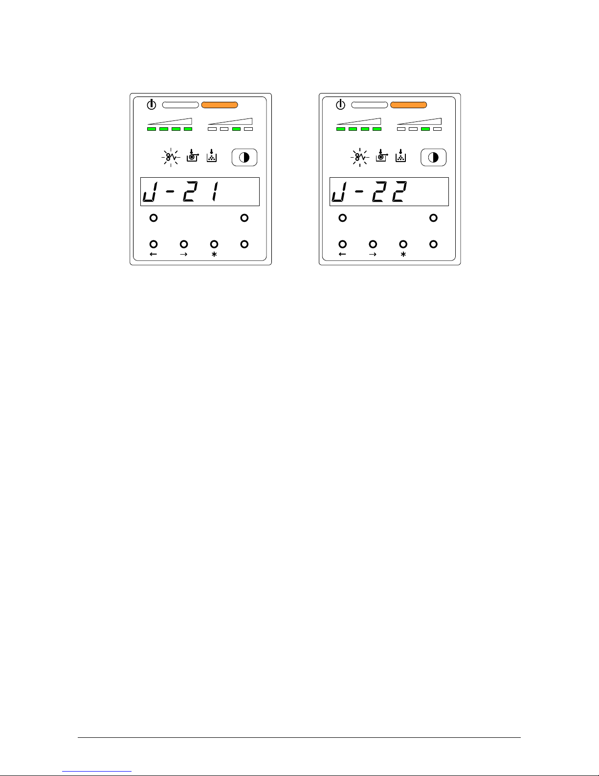
4. 1. 5 Paper Mis-feed in Outer Device (J-21, J-22)
When the Paper Mis-feed occurs in Outer Device, the Sub Display Panel indicates either of
“J-21” or “J-22”.
TONER REMAI N IMAGE DENSITY
job
MENU TEST
ENTER
Clear the mis-feed using the following procedure:
1) As for the way to clear the mis-feed, refer to the User’s Manual for the Outer Device.
TONER REMAI N IMAGE DENSITY
job
MENU TEST
ENTER
Part 1 Basic Functions 1-68
Page 75
4. 2 Open Cover Errors
The Sub Display Panel will indicate the error code (U-XX) if there are any open decks or open
covers.
Close each deck (or cover) as it is impossible to print, if this error exists.
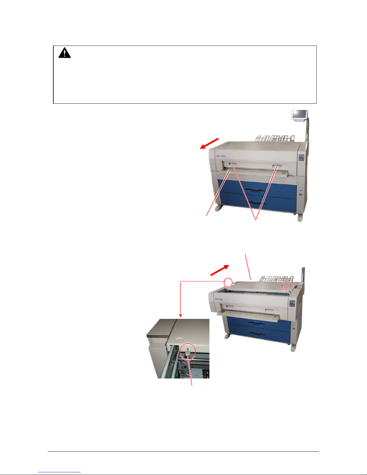
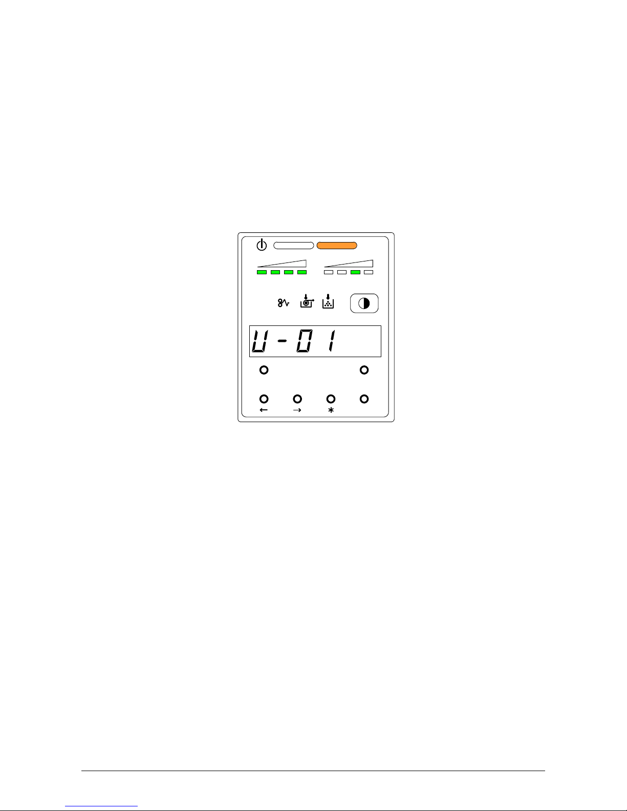
4. 2. 1 Roll Deck Open (U-01, U-02)
The corresponding Roll Deck is opened when the Sub Display Panel indicates “U-01” or “U-02”.
U-01 : Upper Roll Deck is opened.
U-02 : Lower Roll Deck is opened.
(Example : Upper Roll Deck is opened.)
Firmly close the Roll Deck by pressing a little strongly toward the machine.
TONER REMAI N I MAGE DENSI TY
job
MENU TEST
ENTER
Part 1 Basic Functions 1-69
Page 76

NOTE
This error code will be indicated if the Roll Deck is not locked correctly, although it may look
closed.
Open and close the Roll Deck again, pushing until locked. Ensure both sides of the roll deck
are in their correct position.
The Roll Deck is firmly locked.
The Roll Deck is unlocked.
Close the deck firmly.
OK
NG
Part 1 Basic Functions 1-70
Page 77
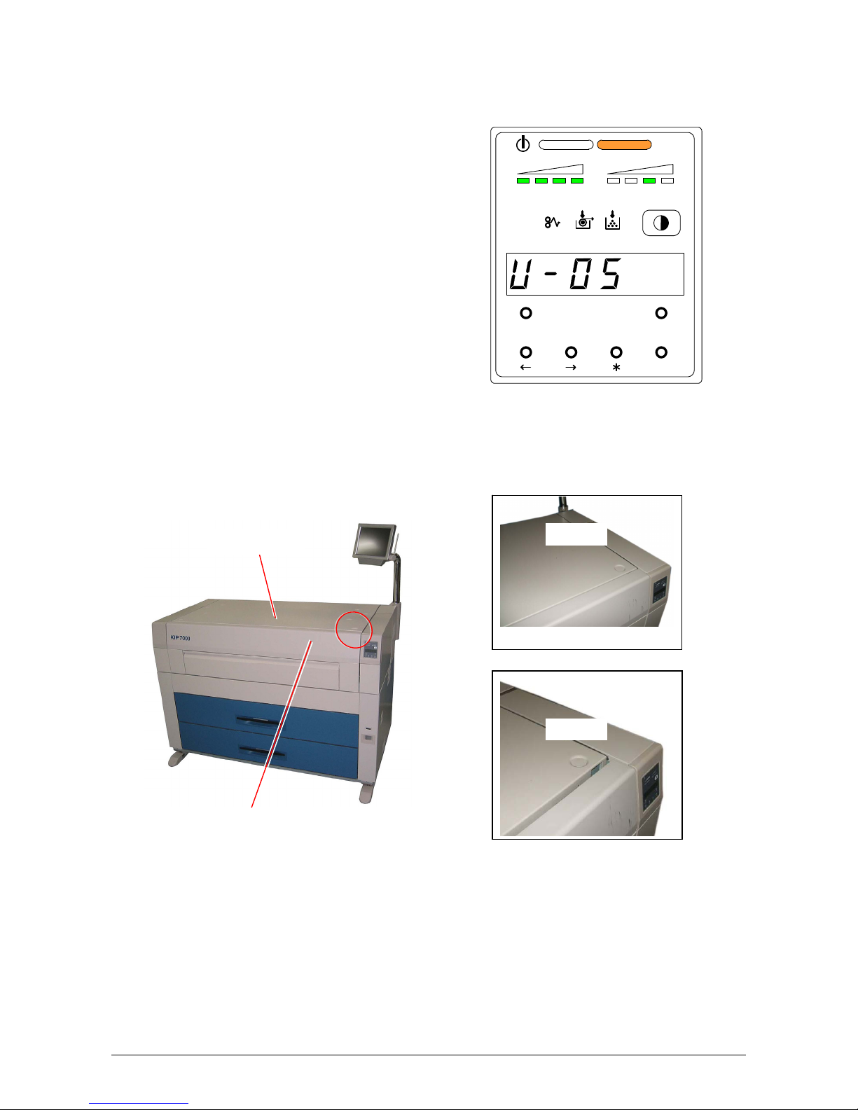
4. 2. 2 Upper Frame Unit / Top Cover Open (U-05)
When either the Upper Frame Unit or the Top Cover is opened the Sub Display Panel indicates
“U-05”.
Check if the Upper Frame Unit and the Top Cover are closed firmly.
Top Cover
Upper Frame Unit
TONER REMAIN I MAGE DENSITY
job
MENU TEST
ENTER
OK
NG
Part 1 Basic Functions 1-71
Page 78
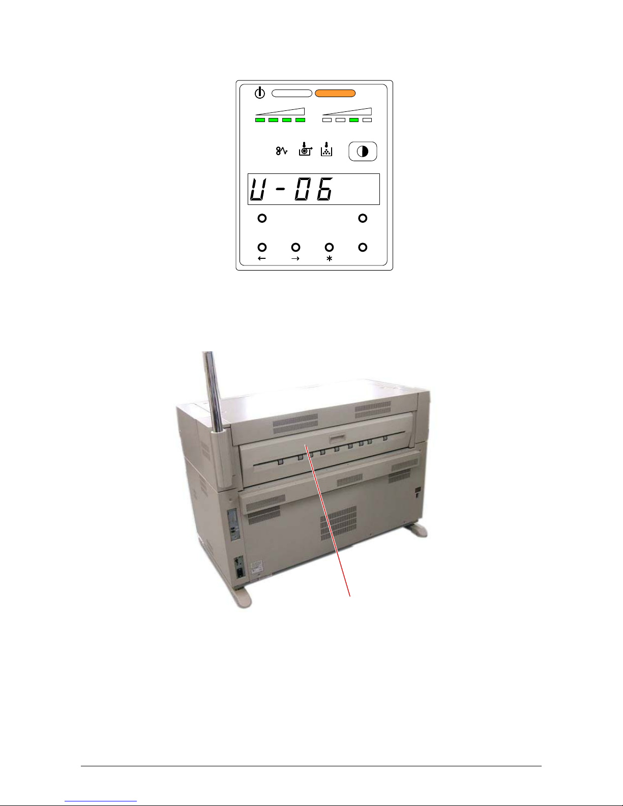
4. 2. 3 Exit Cover Open (U-06)
When the Exit Cover is opened, the Sub Display Panel indicates “U-06”.
Close the Exit Cover.
TONER REMAIN IMAGE DENSITY
job
MENU T EST
ENTER
Exit Cover
Part 1 Basic Functions 1-72
Page 79
4. 3 Other Errors
4. 3. 1 Toner Low
The machine indicates a “Toner Low” by lighting the Toner Low Indicator on the Sub Display Panel.
Toner Cartridge replacement is required.
Refer to [2.4 Replacing the Toner Cartridge] on page 1-32.
Toner Low Indicator
TONER REMAIN IMAGE DENSITY
job
MENU TEST
ENTER
Part 1 Basic Functions 1-73
Page 80

4. 3. 2 Roll Empty
The machine indicates a “Roll Empty” by lighting the Roll Empty Indicator on the Sub Display
Panel if the roll media currently in use is consumed during printing.
Installation of a new roll is required.
Refer to [2.3 Replacing the Roll Media] on page 1-23.
Roll Empty Indicator
TONER R EMAIN I MAGE DENSI TY
job
MENU TEST
ENTER
Part 1 Basic Functions 1-74
Page 81

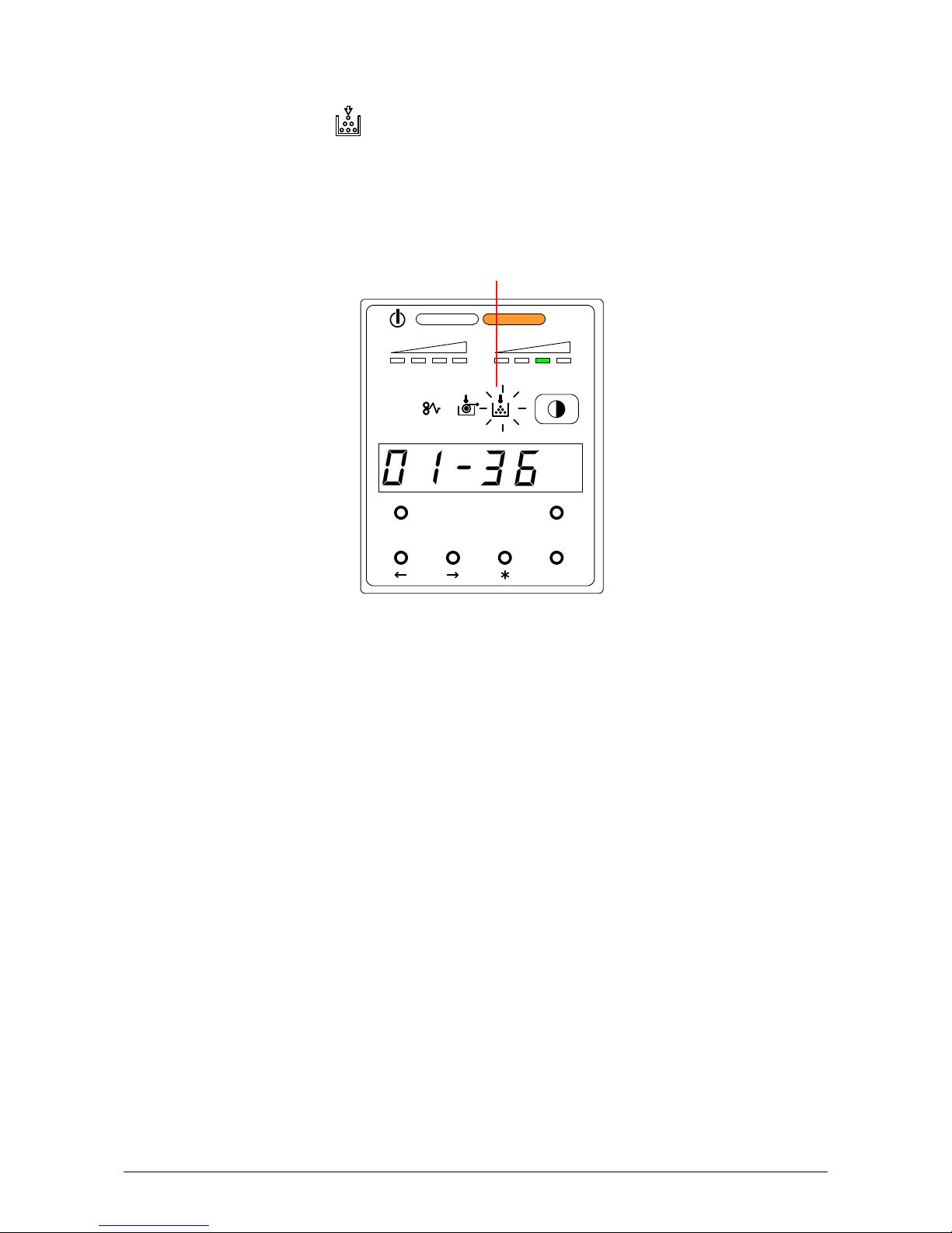
4. 3. 3 No Manual Paper (P.E.)
The machine indicates “P.E.-XX” on the Sub Display Panel when the cut sheet paper is not set on
the Manual Feeder. “XX” means the required paper size.
Set the indicated size of paper.
Refer to [2.5 Setting the Cut Sheet Paper] on page 1-36.
When the Manual Paper is inserted, indication is changed from [P.E.] to [b.p.] automatically.
TONER REMAIN IMAGE DENSITY
job
Required paper size
MENU TEST
ENTER
TONER REMAI N IMAGE DENSITY
job
MENU TEST
ENTER
Part 1 Basic Functions 1-75
Page 82

4. 4 Call Service Errors
You will note one of the following Error Codes on the Operation panel if the machine has the fatal
error.
It is impossible for the user to cure these errors to resolve these issues.
PLEASE CALL YOUR TRAINED SERVICE PERSONNEL TO RESOLVE THESE ERRORS.
Error Code Name of the error
E - 01 Fuser Temperature Rising Error
E - 02 Fuser Over Temperature Error
E - 03 Main Motor Error
E - 04 Developer Error
E - 06 Counter Error
E - 07 Cutter Error
E - 14 Fuser Motor Error
E - 16 Wire Cleaning Error
E - 21 Fuser Thermostat Error
E - 23 LED Head Cleaning Error
E - 40 Outer Device Error
E - 41 Key Card Error
E - 51 High Voltage Power Error
If any of the above errors is displayed:
1) Turn off the printer, wait approximately 30 seconds, and then turn on the printer again.
2) If the same error code is displayed, turn off the printer, and then unplug the printer from the wall
outlet.
Call your service personnel.
Part 1 Basic Functions 1-76
 Loading...