

Page 1

WARRANTY COVERAGE :
Daedong-USA, Inc., DAEDONG Tractor Division, herein referred to as DAEDONG, undertakes to replace
or repair any part of a DAEDONG loader where damage has been proven to be caused by defects in
material or workmanship.
This Warranty is valid for a period of 1 year from the date of the original retail sale. Parts replaced or
repaired under the terms of this Warranty are guaranteed only until the original warranty expires. Warranty
only applies to the original purchaser.
It is further understood and agreed that the defect should be immediately reported to the Selling Dealer. The
Selling Dealer will generally perform Warranty repairs or replacements and the Purchaser shall deliver the
DAEDONG loader to the Dealer’s place of business for repair.
The obligation of
DAEDONG to the Purchaser under this Warranty is limited to the repair or replacement of
defective parts by an authorized DAEDONG dealer. Repair or replacement in accordance with this Warranty
shall constitute fulfillment of all liabilities of DAEDONG and the Selling Dealer in respect to DAEDONG
loader.
There are no warranties beyond those which expressly appear herein. Any implied warranty of
merchantability or tness for a particular purpose is specically excluded here from.
WARRANTY CONDITIONS
KL701-AU-00.indd 1 2013-03-29 오전 11:24:43
Page 2

WARRANTY PROVISIONS :
DAEDONG’s liability under this warranty is subject to the observance by the Purchaser of the following provisions:
1. The purchaser shall at all times in the operation of any DAEDONG Product, use those brands and grades of
lubricating oils, lubricants or fuel and spare parts ofcially approved by DAEDONG.
2. The DAEDONG loader shall have been used in accordance with the procedures specified in the Operator’s
Manual. This Warranty does not extend to damage resulting from misapplication, abuse, misuse, failure to preform
maintenance, negligence, re, accidents or changes or faulty mounting carried out by the Purchaser. When making a
Warranty exchange of parts, the Purchaser shall compensate DAEDONG for the time that the parts have been used
if they have been exposed to extreme wear.
3. Compensation is not paid for physical harm, deadlock, resulting damages or other losses.
4. To obtain warranty service, the Purchaser must (1) report the product defect to an authorized DAEDONG dealer and
request repair within the applicable warranty term and (2) present evidence of purchase.
5. The Warranty shall be void if the DAEDONG loader has been altered or repaired outside of a DAEDONG dealership
or travel of dealer personnel to customer location for Warranty repair. The customer shall also pay any premium for
overtime labor requested by the dealership
6. Temporary repairs or additional costs due to the work being performed after normal working hours will not be
compensated.
7. The above warranty is in lieu of all other warranties on DAEDONG’s behalf and neither party assumes any other
liability in connection with DAEDONG’s Products.
8. Any dispute arising between DAEDONG and the Purchaser concerning the liability of DAEDONG under this warranty
shall be subject to the laws of the State of North Carolina.
RIGHT TO MAKE DESIGN AND PRODUCT CHANGES:
DAEDONG reserves the right to make changes in the design and other changes in its DAEDONG Products
at any time without incurring any obligation with respect to any product previously ordered, sold or shipped.
WARRANTY CONDITIONS
WARRANTY CONDITIONS
KL701-AU-00.indd 2 2013-03-29 오전 11:24:43
Page 3
Make sure all potential operators of this equipment review this manual and all safety messages contained
within.
PLEASE NOTE
SIGNS DESCRIPTION
CAUTION
This mark indicates important safety messages in this manual. When you see
this symbol, carefully read the message that follows and be alert to the possibility of personal injury or death.
WARNING
IMPORTANT
NOTE
This mark indicates potentially hazardous situation which, if not observed, may
result in death or moderate injury.
This mark indicates emphasis on notable characteristics in working proce-
dures or information on working procedures and technology for convenient
use.
This mark indicates general comments or notes.
KL701-AU-00.indd 3 2013-03-29 오전 11:24:44
Page 4

KL701-AU-00.indd 8 2013-03-29 오전 11:24:44
Page 5
SAFETY PRECAUTIONS
..............................................................
SAFETY DECALS.........................................................
................
LOADER SPECIFICATIONS
.........................................................
INTRODUCTION
............................................................................
TRACTOR PREPARATION
...........................................................
LOADER OPERATION
..................................................................
LOADER REMOVAL
....................................................................
LOADER MOUNTING
....................................................................
LUBRICATION AND MAINTENANCE
...........................................
TROUBLE SHOOTING
..................................................................
HYDRAULIC SYSTEM
.................................................................
TORQUE TIGHTENING CHARTS
.................................................
SECTION
CONTENT I
12
11
10
9
8
7
6
5
4
3
2
1
KL701-AU-00.indd 5 2013-03-29 오전 11:24:44
Page 6

KL701-AU-00.indd 8 2013-03-29 오전 11:24:44
Page 7

PARTS ILLUSTRATIONS
..............................................................
ILLUSTRATIONS ...................................................................................13-2
BUCKET, QUICK ATTACHMENT ..........................................................
13-4
4IN1 BUCKET ASSEMBLY ....................................................................
13-6
FRONT GRILL ASSEMBLY (OPTIONAL) ..............................................
13-10
MOUNTING FRAME ASSEMBLY ..........................................................
13-12
BOOM ASSEMBLY ................................................................................
13-14
BOOM HYDRAULIC ASSEMBLY ..........................................................
13-18
BOOM HYDRAULIC ASSEMBLY (4IN1 STD) .......................................
13-22
AUXILIARY HYDRAULIC DEVICE (OPTION) .......................................
13-28
BOOM CYLINDER ASSEMBLY-LH .......................................................
13-30
BOOM CYLINDER ASSEMBLY-RH
.......................................................13-32
BUCKET CYLINDER ASSEMBLY .........................................................
13-34
DECALS ................................................................................................13-36
SECTION
CONTENT II
13
LOADER INSTALLATION
.............................................................
INDEX
..........................................................................................
14
15
KL701-AU-00.indd 7 2013-03-29 오전 11:24:44
Page 8

KL701-AU-00.indd 8 2013-03-29 오전 11:24:44
Page 9

1
1. SAFETY PRECAUTIONS
SAFETY ...................................................................................................1-2
SAFETY PRECAUTIONS .........................................................................
1-2
KL701-AU-01.indd 1 2013-03-29 오전 11:25:03
Page 10
1-2 KL701
Un der sta nd that your safety and the safety of other
persons is measured by how you service and operate this
loader. Know the position and operations of all controls
before you try to operate. Make sure you check all
controls in a safe area before starting.
Read this manual completely and thoroughly and
make sure you understand all controls. All equipment has
a limit. Make sure you are aware of the stability and load
characteristics of this loader before you begin operation.
The safety information given in this manual does not
replace any safety codes, insurance needs, federal, state
and local laws. Make sure your machine has the correct
equipment required by your local laws and regulations.
SAFETY SAFETY PRECAUTIONS
Before starting the engine of your tractor, make sure all
operation controls are in park lock or neutral position.
Operate controls only when seated in the operator’s seat.
Equip your tractor with a ROPS cab or frame for your
protection. See your tractor operator’s manual for correct
seat belt usage.
A frequent cause of personal injury or death is persons
falling off and being run over. Do not permit others to ride
on your tractor. Only one person, the operator, should be
on the machine when it is in operation.
Before leaving the tractor, stop the engine, put all controls
in neutral, engage the parking brake and remove the key
from the ignition.
When using remote hydraulic tractor valves on some
tractors, the loader lift and dump cylinders will continue
moving unless the control levers are manually returned
to neutral, or until relief pressure is reached at the ends
of piston strokes. Observe the bucket movement and
maintain control with the control levers.
Stop the loader arms gradually when lowering or lifting
loads.
Stay off of slopes too steep for safe operation. Shift down
before you start up or down a hill with a heavy load. Avoid
“free wheeling”.
This safety alert symbol indicates important safe-
ty messages in this manual. When you see this
symbol, carefully read the message that follows
and be alert to the possibility of personal injury or
death.
CAUTION
KL701-AU-01.indd 2 2013-03-29 오전 11:25:04
Page 11
SAFETY PRECAUTIONS 1-3
1
Trave l spe ed sh ould be s u ch t hat c ompl ete c ontr o l
and machine stability is maintained at all times. Where
possible, avoid operation near ditches, embankments and
holes. Reduce speed when turning, crossing slopes, and
on rough, slick or muddy surfaces.
Nev er use your hand to che c k for susp e cted l eaks
under pressure. Use a piece of cardbord or wood for this
purpose. Escaping hydraulic oil or diesel fuel leaking
under pressure can have sufcient force to penetrate the
skin and cause infection or serious injury, seek medical
attention immediately.
To prevent personal injury, relieve all pressure before
disconnecting uid lines.
Bef o r e apply i n g hydr a u lic pre s s ure, m a k e sure a l l
hydraulic connections are tight and components are in
good condition.
Contact with overhead power lines can cause severe
electrical burn or death from electrocution.
Make sure there is enough clearance between raised
equipment and overhead power lines.
Add recommended rear tire liquid weight or rear wheel
weights for increased stability.
A loade r at tachment shoul d be transp ort ed i n a low
position at slow ground speeds. Make turns slowly and
use the tractor brakes cautiously. A loaded attachment in
the raised position alters the center of gravity location of
the machine and increases the possibility of mishaps.
Do not stand, wal k or work under a ra ised l oader or
att achme n t unl e ss i t is s e curel y bloc k ed o r held in
position. Accidental movement of a control lever or leak
in the hydraulic system could cause the loader to drop, or
attachment to dump, causing severe injury.
Make sure all parked loaders on stands are on a hard
level surface with all safety devices engaged to prevent
load e r from fal l i n g and bei n g damaged o r injuring
someone.
When using a loader, be alert of bucket position at all
times. Loader in raised position with bucket rolled back
can dump material on tractor causing damage or injury to
tractor and / or operator.
Always park loader with bucket attached to loader.
KL701-AU-01.indd 3 2013-03-29 오전 11:25:04
Page 12

MEMO
............................................................................................................................................................................
............................................................................................................................................................................
............................................................................................................................................................................
............................................................................................................................................................................
............................................................................................................................................................................
............................................................................................................................................................................
............................................................................................................................................................................
............................................................................................................................................................................
............................................................................................................................................................................
............................................................................................................................................................................
............................................................................................................................................................................
............................................................................................................................................................................
............................................................................................................................................................................
............................................................................................................................................................................
............................................................................................................................................................................
............................................................................................................................................................................
KL701-AU-01.indd 4 2013-03-29 오전 11:25:04
Page 13

2
2. SAFETY DECALS
SAFETY DECALS .....................................................................................2-2
SAFETY DECAL LOCATIONS ......................................................................................2-2
KL701-AU-02.indd 1 2013-03-29 오전 11:25:23
Page 14
2-2 KL701
SAFETY DECALS
SAFETY DECAL LOCATIONS
Care of Safety Decals.
1. Keep safety decals clean and free of obstructing material.
2. Clean safety decals with soap and water and dry with a soft cloth.
3. Replace damaged or missing safety decals with new decals from your DAEDONG Dealer.
4.Ifacomponentwithasafetydecal(s)afxedisreplacedwithanewpart,makesurenewsafetydecal(s)areattached
in the same location(s) as the replaced components.
5. Mount new safety decals by applying on a clean dry surface and pressing air bubbles to outside edges.
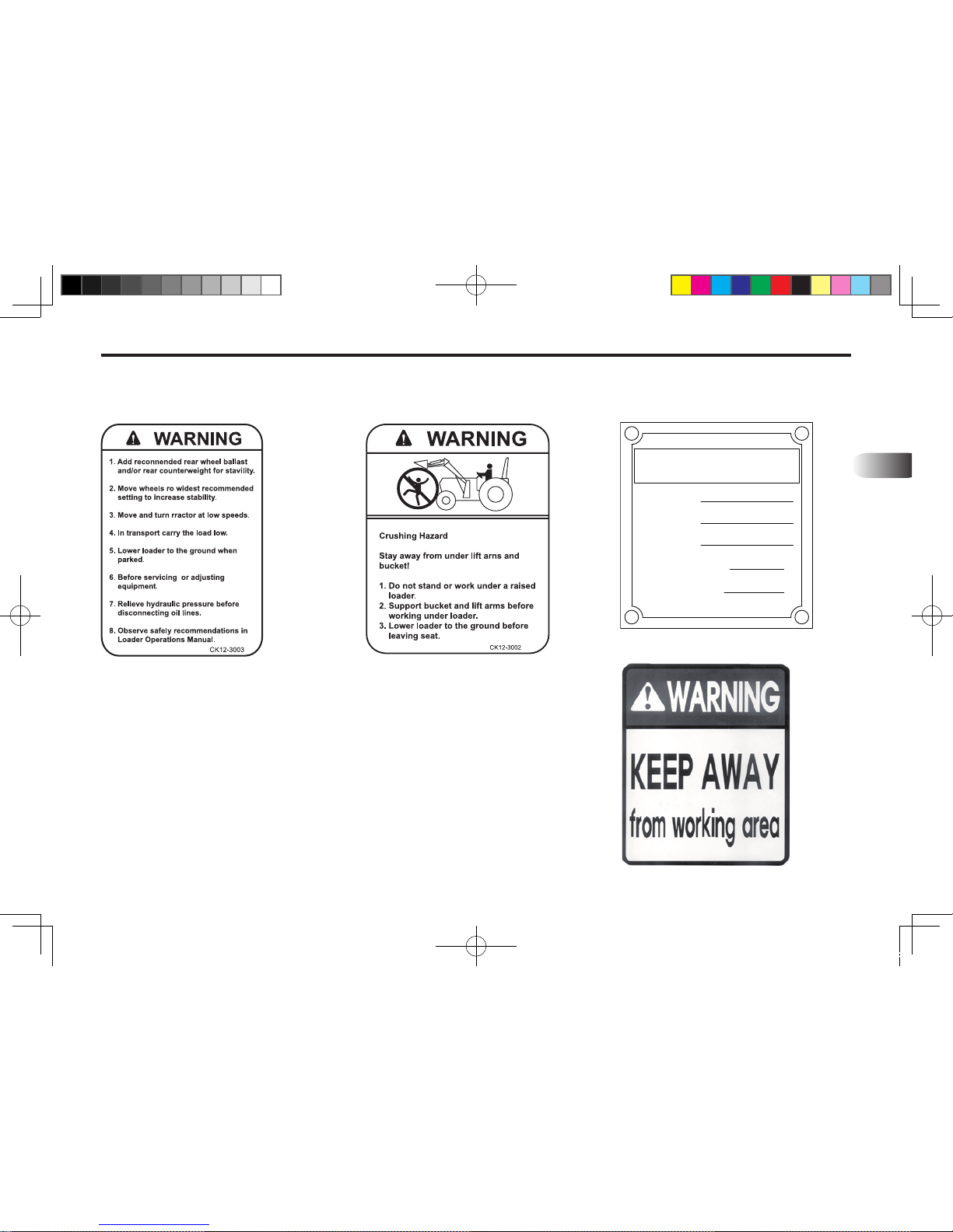
(1) Part No : 3101E-00001 (2) Part No : 3101E-00156 (3) Part No : 3102E-00001
Warning decals 3102E-00001, located on the left hand Mid-Mount and Warning Decal 3102E-00002,
3102E-00003 located on the loader right hand Mid-Mount are visible when getting on tractor.
IMPORTANT
KL701-AU-02.indd 2 2013-03-29 오전 11:25:25
Page 15
2
SAFETY DECALS 2-3
(4) Part No : 3102E-00003 (5) Part No : 3102E-00002 (6) Part No : 3104E-00030
(7) Part No : 3102E-00014
{Gt
sGt
zGu
jG~
yGvGs
O~p{oGjv|u{lyG~lpno{P
rpv{p
[WWTXSGqTSGjTGjTS
nSG]\ZT_W]GyUGGr
kvGuv{GljllkGyUvUsU
{UGaGR_YT\\T\ZWT^XWYGGGGGmUGaGR_YT\\T\ZWT^XXZ
KL701-AU-02.indd 3 2013-03-29 오전 11:25:28
Page 16

MEMO
............................................................................................................................................................................
............................................................................................................................................................................
............................................................................................................................................................................
............................................................................................................................................................................
............................................................................................................................................................................
............................................................................................................................................................................
............................................................................................................................................................................
............................................................................................................................................................................
............................................................................................................................................................................
............................................................................................................................................................................
............................................................................................................................................................................
............................................................................................................................................................................
............................................................................................................................................................................
............................................................................................................................................................................
............................................................................................................................................................................
............................................................................................................................................................................
KL701-AU-02.indd 4 2013-03-29 오전 11:25:28
Page 17

3
3. Loader SpecificationS
Loader SpecificationS .................................................................... 3-2
KL701-AU-03.indd 1 2013-03-29 오전 11:25:45
Page 18
3-2 KL701
Loader SpecificationS
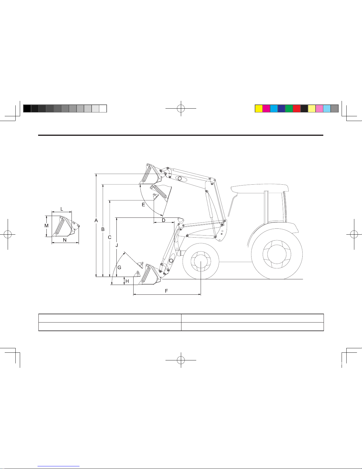
Specications and design are subject to change without prior notice.
601O301A
Loader ModeL KL701
Tractor Model RX7320
KL701-AU-03.indd 2 2013-03-29 오전 11:25:45
Page 19
3
LOAdeR SpecificAtiOnS 3-3
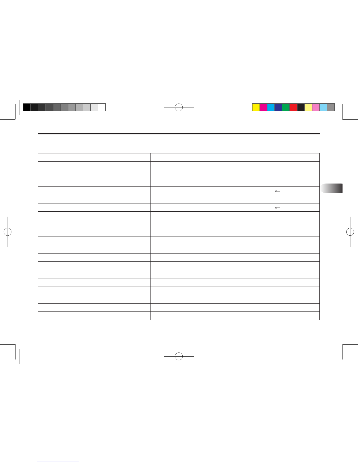
a Maximum Lift Height 3,400mm 133.9 in
B Clearance with Attachment Level 3,123mm 123.0 in
c
Clearance with Attachment Dumped 2,599mm
102.3 in
d Reach at Maximum Height 45° 519mm 20.4 in
e Maximum Dump Angle 47° ←
f Reach with Attachment on Ground 2,043mm 80.4 in
G Attachment Rollback Angle 54° ←
H Digging Depth Below Grade
166mm
6.5 in
J Overall Height in Carry Position 1,760mm 69.3 in
L Depth of Attachment (to back of inner shell) 592mm 23.3 in
M Height of Attachment 581mm 22.9 in
n Depth of Attachment (to pivot pin) 838mm 33.0 in
S Lift Capacity to Full Height at Pivot Pins 1,535 kgf 3,384 lbs
t Breakout Force at Pivot Pins 2,431 kgf 5,359 lbs
Lift Cylinder ø70mmX572mm Ø2.8X23.2 in
Bucket Cylinder ø70mmX405mm Ø2.8X15.9 in
Bucket Width 2130mm 82 in
Bucket Weight 194 Kg 428 lbs
Approx. Weight (without Bucket) 666 Kg 1,468 lbs
Bucket Capacity 0.60m³ (0.38m³) 21.2 ft³ (13.2 ft³)
KL701-AU-03.indd 3 2013-03-29 오전 11:25:46
Page 20

MeMo
............................................................................................................................................................................
............................................................................................................................................................................
............................................................................................................................................................................
............................................................................................................................................................................
............................................................................................................................................................................
............................................................................................................................................................................
............................................................................................................................................................................
............................................................................................................................................................................
............................................................................................................................................................................
............................................................................................................................................................................
............................................................................................................................................................................
............................................................................................................................................................................
............................................................................................................................................................................
............................................................................................................................................................................
............................................................................................................................................................................
............................................................................................................................................................................
KL701-AU-03.indd 4 2013-03-29 오전 11:25:46
Page 21

4
4. INTRODUCTION
INTRODUCTION ....................................................................................... 4-2
WARRANTY REGISTRATION .......................................................................................4-2
SERIAL NUMBER AND LOCATION ..............................................................................4-2
KL701-AU-04.indd 1 2013-03-29 오전 11:26:10
Page 22
4-2 KL701
INTRODUCTION
WARRANTY REGISTRATION
The Delivery and Warranty Registration forms must be
lled out and signed to validate your warranty protection.
The items on the form under "I hereby Acknowledge"
should be read and understood. The terms and conditions
of the warranty on this machine are specied in the front
of this manual.
SERIAL NUMBER AND LOCATION
The serial number is important information about the
ma chine a nd i t may be necessa ry t o kn ow i t be fore
obtaining the correct replacement part. The serial number
is located on the right side of loader sub-frame. The
serial number should be recorded on the Delivery and
Registration form and also below for your reference.
The purpose of this manual is to assist you in maintaining
and operating your DAEDONG loader. Read it carefully,
it furnishes information and instructions that will help you
achieve years of dependable performance. Some information may be general in nature due to unknown and
varying conditions. However, through experience and
these instructions, you should be able to develop operating procedures suitable to your particular situation.
"Right" and "Left" as used throughout this manual are
determined by facing the direction the machine will travel
when in use.
The photos, illustrations and data used in this manual are
current at the time of printing, but due to possible in-line
production changes, your machine may vary slightly in
detail. The manufacturer reserves the right to redesign the
machine as may be necessary without notication.
DAEDONG KL701 Loader serial number information
Date purchased
Loader serial number
Dealer name and telephone number
Illustrations used in this manual may not show all
safety equipment that is recommended to ensure safe
operation of tractor and loader. Refer to the Safety Precautions section of this manual for information
concerning safety. Consult your dealer for further in-
formation.
IMPORTANT
KL701-AU-04.indd 2 2013-03-29 오전 11:26:10
Page 23

5
5. TRACTOR PREPARATION
TRACTOR PREPARATION ..................................................................... 5-2
REAR COUNTERWEIGHT ............................................................................................5-2
ROPS SYSTEM .............................................................................................................5-2
TRACTOR HYDRAULIC SYSTEM ................................................................................5-2
TRACTOR TIRES ..........................................................................................................5-3
TIRE INFLATION ...........................................................................................................5-3
WHEEL TREAD SETTINGS ..........................................................................................5-3
FRONT COUNTERWEIGHT .........................................................................................5-3
KL701-AU-05.indd 1 2013-03-29 오전 11:27:00
Page 24
5-2 KL701
TRACTOR PREPARATION
REAR COUNTERWEIGHT
The use of adequate counterweight to counter balance
for maximum loader capacity is required for safe loader
operation.
Weight added to rear of the tractor provides better traction
and easier, more efficient loader operation. The tractor
can be counterweighted by filling rear tires with liquid
calcium solution and/or by the installation of rear wheel
weights.
Additi onal counterweigh t requir ements will vary with
load e r a t tach m e n t s and eq u i p ment ap p l i catio n s .
Additional weight can be added by installation of Three
Point Hitch mounted ballast.
Refer to tractor operator's manual for specific recommendations on counterweighting tractor.
ROPS SYSTEM
The tractor must be equipped with an approved ROPS
system to ensure adequate operator's protection.
TRACTOR HYDRAULIC SYSTEM
Tractor operation in a loader application significantly
incr eases demands on the tractor hydra ulic s ystem .
Ch eck the tra cto r hy draulic sys tem fluid leve l da ily.
Refer to your tractor operator's manual maintenance
section for instructions regarding tractor hydraulic system
maintenance.
Adhere to recommendations in your tractor operator's
manual concerning hydraulic uid and lter specications,
and change intervals.
Add recommended rear tire liquid weight, rear
wheel or rear ballast for increased stability.
Do not exceed the manufacturer's rating for maxi-
mum gross vehicle weight.
Refer to operator's manual or ROPS serial plate
provided with tractor.
CAUTION
Certain specific conditions may not permit safe
use of loader at loader rating or may require more
careful restricted operation at the rated load.
CAUTION
KL701-AU-05.indd 2 2013-03-29 오전 11:27:00
Page 25
TRACTOR PREPARATION 5-3
5
TRACTOR TIRES
Selection of tires of tires (size, prole, tread type) should
be restricted to tire recommendations as specified by
DAEDONG.
TIRE INFLATION
Fr o n t ti r es mu st be m a i nt a i n ed at t h e m a x im u m
recommended ination to maintain normal tire prole with
the added weight of loader/material.
Rear tires must be maintained at equal pressure within
the recommended tire inflation range. Unequal rear tire
inflation can prevent loader attachment from contacting
the ground across its full width.
WHEEL TREAD SETTINGS
Tract or front wheel tread settings must be restrict ed
to whe el t read spa cing rec ommende d in the tra ctor
operator's manual.
The tractor/loader must only be operated with all
safety equipment properly installed.
CAUTION
FRONT COUNTERWEIGHT
Use of front counterweight is not recommended when
tra ctor i s bein g used in a load e r app l icati o n. Fro nt
counterweight adds unnecessary front axle load in loader
applications.
KL701-AU-05.indd 3 2013-03-29 오전 11:27:00
Page 26

MEMO
............................................................................................................................................................................
............................................................................................................................................................................
............................................................................................................................................................................
............................................................................................................................................................................
............................................................................................................................................................................
............................................................................................................................................................................
............................................................................................................................................................................
............................................................................................................................................................................
............................................................................................................................................................................
............................................................................................................................................................................
............................................................................................................................................................................
............................................................................................................................................................................
............................................................................................................................................................................
............................................................................................................................................................................
............................................................................................................................................................................
............................................................................................................................................................................
KL701-AU-05.indd 4 2013-03-29 오전 11:27:00
Page 27

66
6. LOADER OPERATION
LOADER OPERATION .............................................................................6-2
PRECAUTIONARY NOTES ..........................................................................................6-2
INITIAL LOADER OPERATION .....................................................................................
6-3
COLD WEATHER OPERATION ....................................................................................
6-3
LOADING BUCKET .......................................................................................................
6-3
DUMPING BUCKET .....................................................................................................
6-4
TRANSPORTING A LOADED BUCKET ........................................................................
6-4
SCRAPING ....................................................................................................................
6-5
BACKFILLING/BACKGRADING ....................................................................................
6-5
CONTROLLED RATE OF LOADER FUNCTIONS ........................................................
6-5
LOADER HYDRAULIC CONTROLS .............................................................................
6-5
KL701-AU-06.indd 1 2013-03-29 오전 11:27:17
Page 28
6-2 KL701
LOADER OPERATION
PRECAUTIONARY NOTES
Do not lower the edge of the bucket too low for loading. Keep
the bottom of the bucket level with the ground when loading.
We urge you to follow this advice:
1. Rea d and und erstand thi s manual as w ell as the
Tractor Operator's Manual.
2. Remem b e r and o b serve t he Safe t y Preca u tions
brought to your attention in this manual, the tractor
manual and on the machinery itself.
3. Use good common sense in the everyday operation
of this unit. Safety recommendations can never be allinclusive and you are responsible for watching out for
and avoiding unsafe conditions.
4. Never exceed the limits of a piece of machinery. If its
ability to do a job or to do so safely is in question, don't
try it.
5. Don't hurry the learning process or take the unit for
granted. Ease into it and become familiar with your
new loader and tractor.
Do not use the bucket for pushing down material
with bucket cylinders partially extended. Damage
to the cylinders may result.
Do not tip bucket cutting edge down (fully extend-
ed bucket cylinders) during backlling/backgrading operations.
Operation with front tractor wheels off the ground
is not recommended.
Position vehicle to be loaded as near the pile as
possible and in such a direction as to minimize
the amount of tractor turning required to dump.
Do not lower the loader with the tractor engine shut off.
Keep the unit clean and perform regular service.
Observe safety messages whenever cleaning, servicing, or lubricating.
Do not operate bucket cylinders without bucket, it
may damage to the bucket cylinders.
IMPORTANT
When lowering a heavy load, ease it downward
slo wly. N e ver d rop a load e d att achme n t and
"catch it hydraulically". Stopping a load after it
has gained downward momentum places undue
strain on the unit and may cause unnecessary
damage to the loader or tractor or even worse,
personal injury.
CAUTION
The tractor/loader should only be operated with
all safety equipment properly installed.
CAUTION
KL701-AU-06.indd 2 2013-03-29 오전 11:27:18
Page 29
LOADER OPERATION 6-3
6
INITIAL LOADER OPERATION
Before operating the loader, fully raise and lower the boom
two or three times. Then raise the bucket approximately
4 feet above the ground and cycle the bucket cylinders
three times. Lower the bucket to the ground. Check the
tractor hydraulic oil and the correct oil level.
Al ways kee p cyl inde rs i n a r etra cted pos itio n whe n
the loader i s n o t i n us e to guard against rust and
contamination which may cause damage to the cylinder
rods or hydraulic system.
COLD WEATHER OPERATION
For smooth operation in cold weather, let the tractor warm
up. Slowly cycle the lift and bucket cylinders several times
to warm the oil in the hydraulic system. The loader may
operate erratically until the hydraulic oil has warmed to
operating temperatures.
LOADING BUCKET
For the most efficient loading, slowly drive the tractor
straight into the material to be loaded and increase speed
only after contact has been made. Roll the attachment
back a small amount and slowly lift to break away the
materia l. As the lo ad increases, c ontinue r olling th e
attachment back so as to get the maximum load. Remove
th e top lev els firs t wh en lo adin g fr om l arge pil es o f
material. When bucket is full, raise loader so the bucket is
clear of material and slowly back out of the pile.
Before disconnecting hydraulic lines, relieve all
hydraulic pressure. Escaping hydraulic oil under
pressure can have sufficient force to penetrate
the skin causing serious personal injury. If injured
by escaping hydraulic oil seek medical attention
immediately.
Do not operate the loader if the ttings are leak-
ing or if the hoses are damaged. A sudden line
burst would cause the mainframe to drop suddenly, causing damage to the tractor or loader or injury to personnel.
CAUTION
Before leaving the machine, stop the engine, re-
move the key, place all controls in neutral, and either set the parking brake or place tractor in park
as equipped.
CAUTION
Operate controls only when seated in the opera-
tor's seat.
CAUTION
KL701-AU-06.indd 3 2013-03-29 오전 11:27:18
Page 30
6-4 KL701
DUMPING BUCKET
When in the dump area slowly drive the tractor forward
and raise the loader at the same time. Raise the loader to
the height needed to dump the bucket. Make sure to keep
a level bucket position to prevent spilling from the bucket.
Make sure to keep a level bucket position to prevent
spilling from the bucket. Dump the bucket, and keep all
movements smooth.
TRANSPORTING A LOADED BUCKET
Transport material with the bucket as low as possible to
prevent spilling and keep maximum stability. The loader
must be in a position that will not block the operator's
vision. A loaded bucket must not be transported in the
upright position or at excessive speed.
Observe the following safety warnings when transporting
a loaded bucket.
When using a loader, be aware of bucket location
at all times. When raising a loader with bucket
rolled back, material can dump onto tractor causing damage to tractor or injury to operator.
Stop the loader arms gradually when lowering or
lifting. Do not stand, walk or work under a raised
loader unless it is securely blocked or held in position.
Accidental movement of a control lever or leak in
the hydraulic system could cause the loader to
drop, or attachment to dump, resulting in serious
injury or death.
CAUTION
Contact with overhead power lines can cause se-
vere electrical burns or death from electrocution.
Ma ke s ure the re i s cl ear ance betwee n ra ise d
equipment and overhead power lines.
A loaded Bucket should be transported in a low
position at low ground speeds. Make turns slowly
and use the tractor brakes cautiously. A full bucket in the raised position alters the center of gravity location of the machine and increases the possibility of accidents.
WARNING
KL701-AU-06.indd 4 2013-03-29 오전 11:27:18
Page 31
LOADER OPERATION 6-5
6
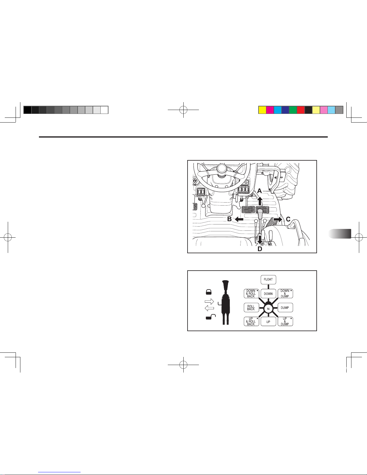
LOADER HYDRAULIC CONTROLS
(A) Forward-Float Low (B) Left-Bucket Retract
(C) Right-Bucket Dump (D) Rear-Raise
130O601A
130O602A
SCRAPING
When scraping, the float position must be used to
keep the bucket on the ground and at the same time
let the bucket follow ground contours. The bucket
must be kept level to the ground during scraping
operations.
BACKFILLING/BACKGRADING
When "Backfilling" or "Backgrading", position the
bucket so it is level on the ground. Do not dump
material fr o m bu c k e t f o l l owing ea c h pa s s , as
additional weight of material in bucket will assist in
"Backgrading" and increases loader efciency during
"Backlling".
CONTROLLED RATE OF LOADER FUNCTIONS
By "feathering" the control lever, reduced operational
speeds can be controlled. This action controls the
position of the valve spool in the valve body and
regulates ow of oil to/from cylinders. It is important
to utilize this operational practice when lowering
loader boom when the bucket is loaded with material.
KL701-AU-06.indd 5 2013-03-29 오전 11:27:19
Page 32
6-6 KL701
The Single lever joystick control lever is mounts on the
RX7320 From the factory.
The control lever has the safety lock function.
Lock the control lever when leaving the tractor while the
Bucket is in the air.
The loader hydraulic valve lift Cylinder circuit incorporates
a “oat” position which allows the loader bucket to follow
ground c ont our s. The "float" p osi tio n is engaged b y
shifting the control lever forward into "detent" until the
operator pulls the control lever out of the “Detent” position.
Refer to "Scraping" operation for recommended use of
“oat” position.
The control valve has a neutral position that prevents
movement of loader or bucket.
When the control valve is released from the work position,
the spool will return to neutral.
Contaminates in hydraulic oil can cause valve
spools to stick. Be alert when operating loader
and follow your Tractor Operator's Manual maintenance schedule.
IMPORTANT
KL701-AU-06.indd 6 2013-03-29 오전 11:27:19
Page 33

7
7. LOADER REMOVAL
LOADER REMOVAL ................................................................................7-2
KL701-AU-07.indd 1 2013-03-29 오전 11:27:46
Page 34
7-2 KL701
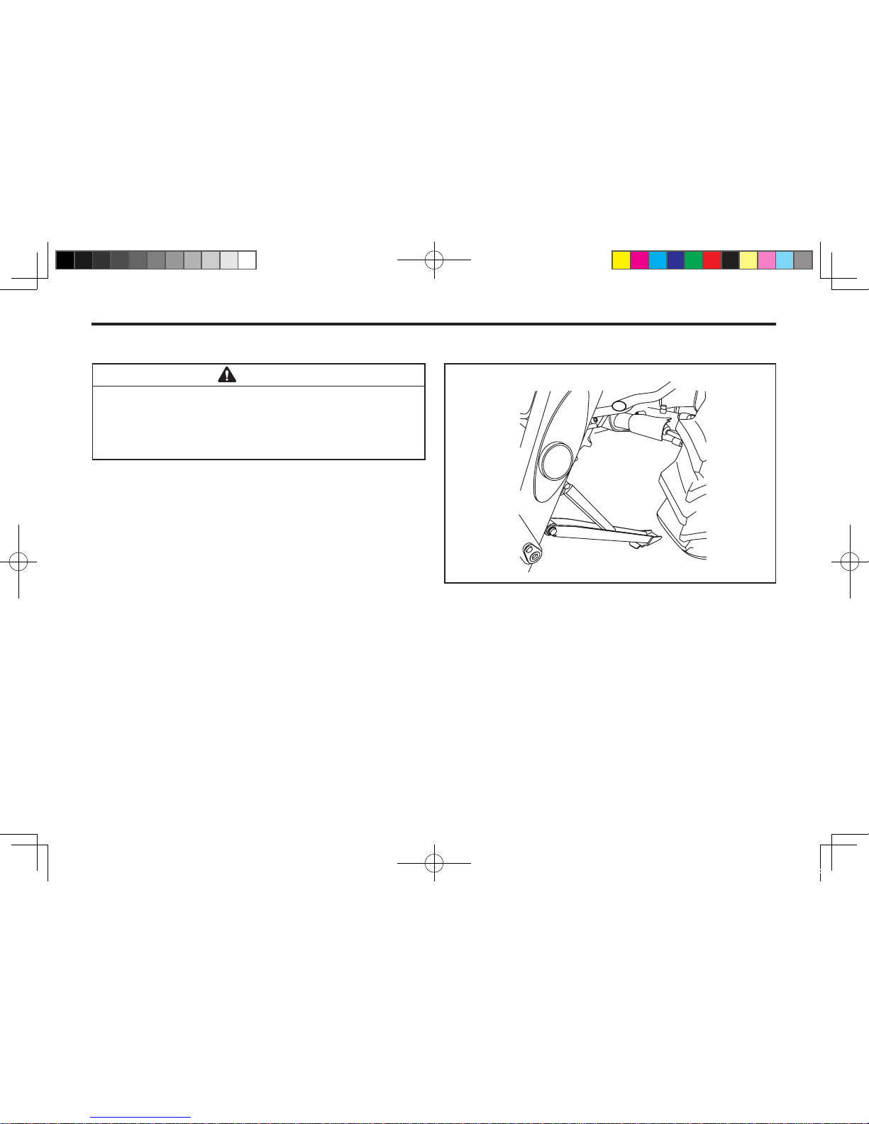
STEP 1.
Park the tractor and loader on hard level surface.
STEP 2.
Raise the boom until the bucket is about 2 feet off the ground.
STEP 3.
Set the parking legs with pivot pin and Keeper.
STEP 4.
Lower the boom until the Parking legs make contact on
the ground. Tip the bucket until the bucket cutting edge
touch the ground.
LOADER REMOVAL
Never park loader without bucket attached to the
loader.
Never allow weight of tractor to be put on parking
leg when removing loader.
CAUTION
601O701A
KL701-AU-07.indd 2 2013-03-29 오전 11:27:46
Page 35
LOADER REMOVAL 7-3
7
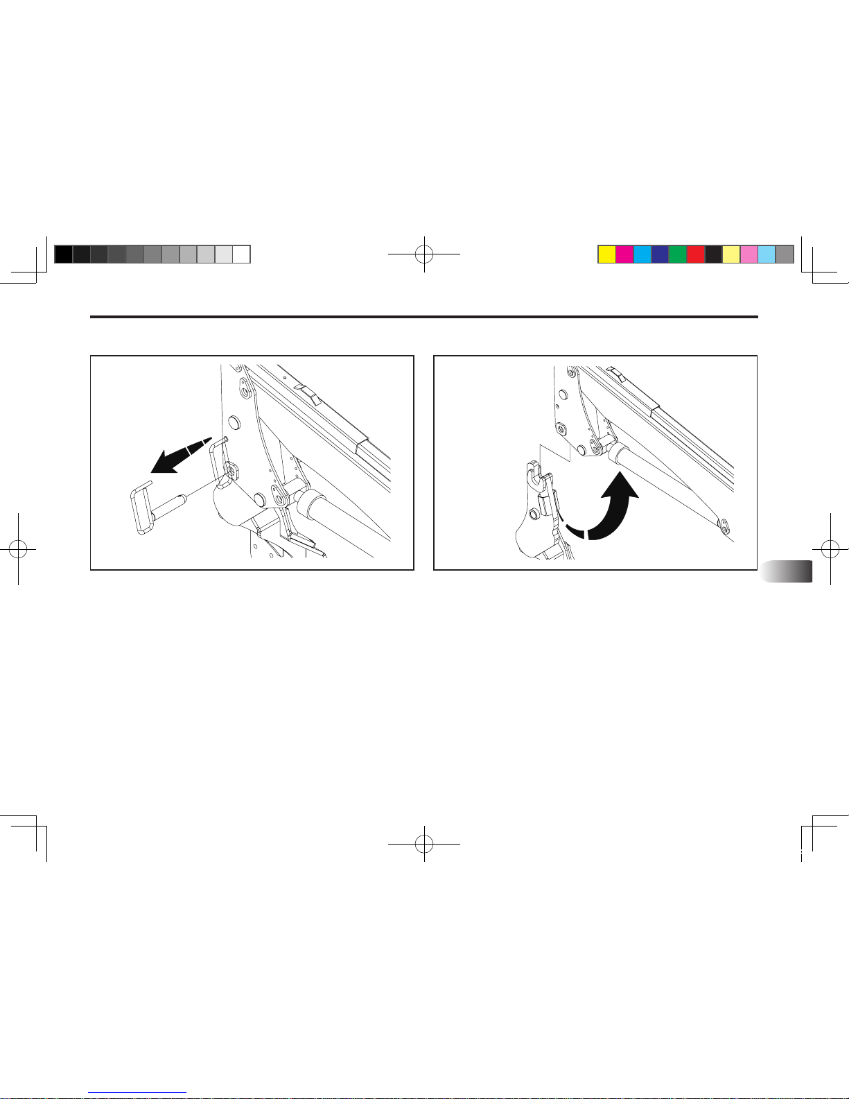
STEP 5.
Remove the latch pin while move the control lever back
and forth slightly to make the latch pin easy.
STEP 6.
Pull the control lever to raise the loader until the loader break
way from the mounting frame. bearing box. Adjust the bucket
until the bottom surface of bucket touch the ground.
STEP 7.
Move the tractor backword slowly and stop to avoid the
hydraulic hoses being tighten.
STEP 8.
Stop the engine and move the control lever back and
forth, left and right several times to reduce the hydraulic
pressure in the hoses.
(1) Latch Pin
701O701A 701O702A
KL701-AU-07.indd 3 2013-03-29 오전 11:27:47
Page 36
7-4 KL701
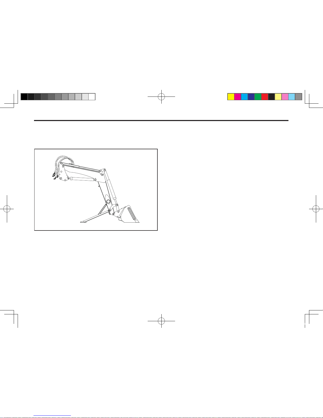
STEP 9.
Disconnect the quick couplers on the hydraulic hoses.
701O703A
KL701-AU-07.indd 4 2013-03-29 오전 11:27:48
Page 37

8
8. LOADER MOUNTING
LOADER MOUNTING .............................................................................. 8-2
KL701-AU-08.indd 1 2013-03-29 오전 11:28:04
Page 38
8-2 KL701
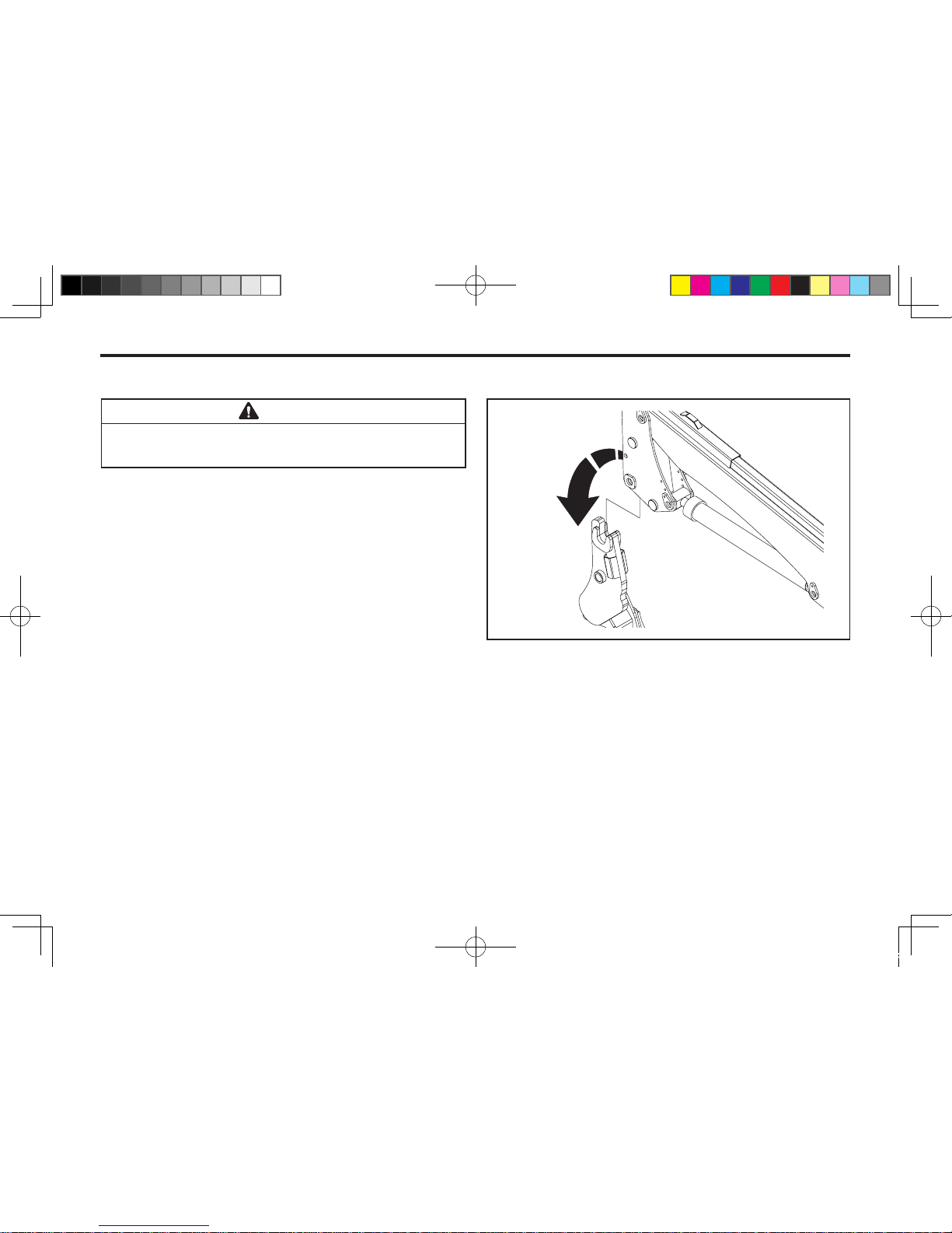
STEP 1.
Carefully drive the tractor into the loader to a position
where the h y d r a u l i c ho ses(Quick coupler) can be
connected to the control valve block.
STEP 2.
Stop the engine and move the control lever back and
forth, left and right several times to reduce the pressure in
the hydraulic hoses.
Connect the hydraulic couplers match the color code
rings.
LOADER MOUNTING
Never allow weight of tractor to be put on parking
leg when mounting loader.
CAUTION
701O801A
KL701-AU-08.indd 2 2013-03-29 오전 11:28:05
Page 39
8
LOADER MOUNTING 8-3
STEP 3.
Start the engine and move the boom and bucket to adjust
the height of loader.
Be sure to check the hook of mounting frame is slightly
higher than the pin welded on loader post.
STEP 4.
Move the tractor forward to put the mounting frame into
the loader post. Stop the tractor when the hook is right
over the pin.
Lower the loader post with moving the boom and bucket
until it hooked securely each other.
STEP 5.
Align the latch pin holes with moving the bucket and
boom. Insert the latch pins.
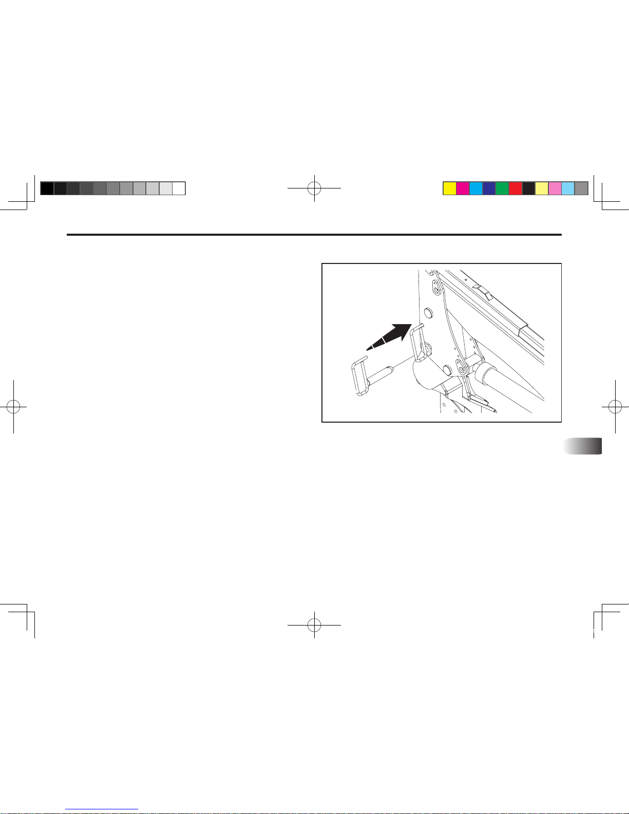
Rubber hammer can be used to put the pin in if needed.
701O802A
(1) Latch Pin
KL701-AU-08.indd 3 2013-03-29 오전 11:28:05
Page 40
8-4 KL701
STEP 6.
Remove pin and keeper holding the parking legs and
return to storage position. Make secure by using pin and
keeper.
KL701-AU-08.indd 4 2013-03-29 오전 11:28:05
Page 41

9
9. LUBRICATION AND MAINTENANCE
LUBRICATION AND MAINTENANCE ...................................................... 9-2
KL701-AU-09.indd 1 2013-03-29 오전 11:28:26
Page 42
9-2 KL701
LUBRICATION AND MAINTENANCE
Refer to "Lubrication and Maintenance Chart" for quick
reference to Maintenance Operations.
Check the tractor hydraulic system as outlined in the
Tractor Operator's Manual.
Do not perform any service or maintenance Opera-
tions with loader raised off the ground. For additional access to tractor components remove loader.
CAUTION
Lower the loader to the ground and relieve pres-
sure in loader hydraulic lines prior to performing any service or maintenance operations on the
tractor or loader.
IMPORTANT
Escaping uid under pressure can have sufcient
force to penetrate the skin, causing serious injury. Before disconnecting lines, be sure to relieve
all pressure. Before applying pressure to the system, be sure all connections are tight and that
lines, pipes and hoses are not damaged.
Fluid escaping from a very small hole can be al
most invisible. Use a piece of cardboard or wood
rather than your hands to search for suspected leaks. If injured by escaping uid, seek medical attention immediately. Serious infection or reaction can develop if correct medical treatment is
not administered immediately.
CAUTION
Do not operate the loader if the ttings are leaking
or if the hoses are damaged. A sudden line burst
could cause the mainframe to drop suddenly, causing damage to the tractor or loader or injury to personnel.
Operate the loader from the tractor seat only.
Do not stand or walk under a raised loader. Acci-
dental movement of control lever or leak in hydraulic system could cause mainframe to drop, causing
severe injury.
WARNING
When checking hydraulic system oil level, the
loader should be on the at land and bucket fully
retracted (all cylinders in retracted position)
Grease all loader pivot points daily (10 hours). Re-
fer to Tractor Operator's Manual for lubricant recommendations.
Inspect hydraulic hoses, connections, control
valve and cylinders for evidence of leakage.
Tractor tires should be maintained at maximum
recommended inflation to maintain normal tire
prole with added weight of loader/material. Unequal rear tire inflation can result in bucket not
being level to the ground.
NOTE
KL701-AU-09.indd 2 2013-03-29 오전 11:28:27
Page 43
LUBRICATION AND MAINTENANCE 9-3
9
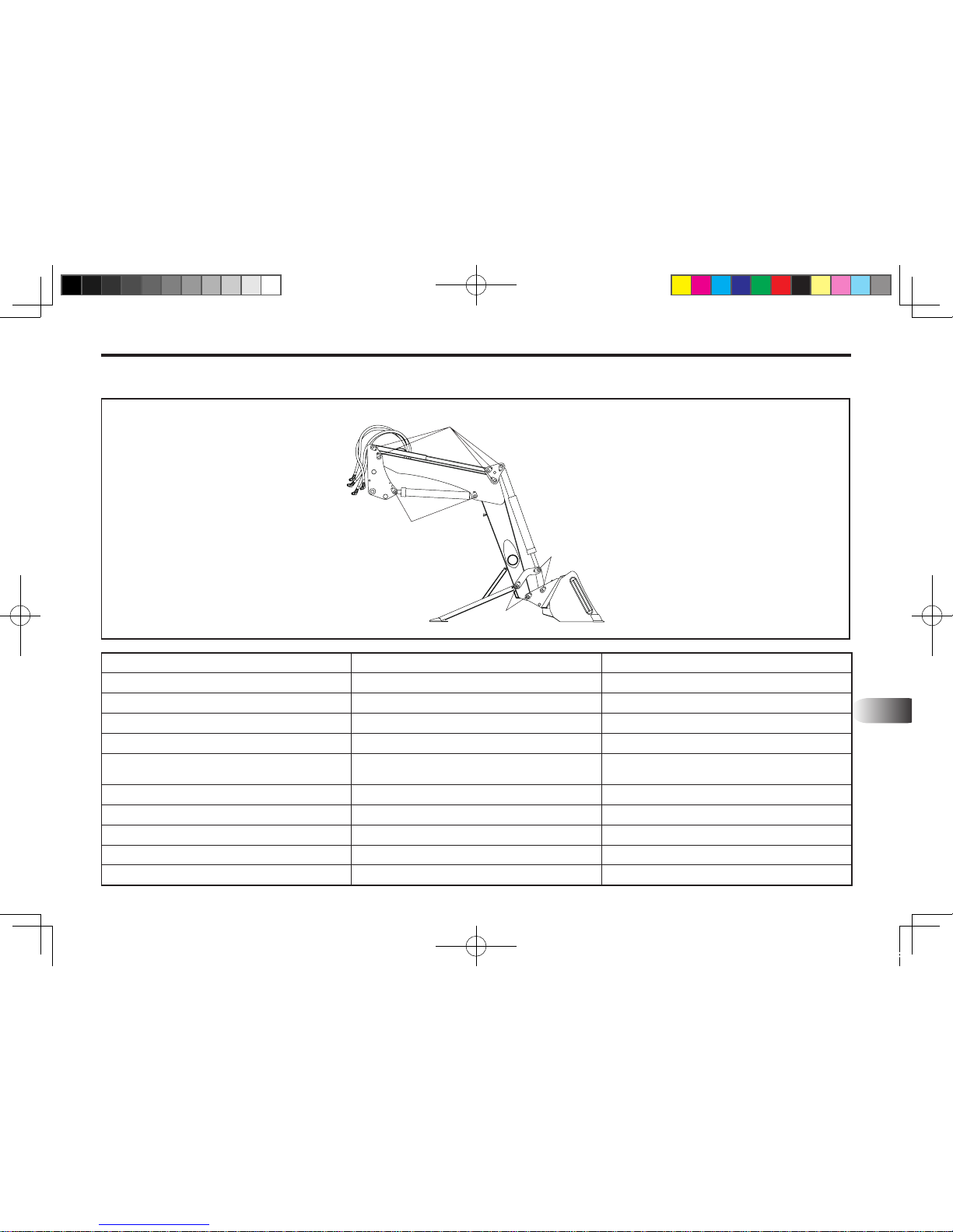
GREASE
GREASE
GREASE
GREASE
ITEM SERVICE SERVICE INTERVAL
Hydraulic System Oil Level Check Daily/10 hours
Hydraulic System Oil /Filter
Replace As specied in Tractor Operator's Manual
Tire Ination Check Weekly/50 hours
Loader Pivot Points
Lubricate Daily/10 hours
Loader Hydraulic Lines, Hoses,
Connections
Check for leaks, wear Daily/10 hours
Lift and Bucket cylinder rod packing Check for seepage, service as needed Daily/10 hours
Pivot pin bolts and dust covers Check, replace if missing Daily/10 hours
lynch pins Check, replace if necessary Daily/10 hours
Loader mount hardwares Check visually Daily/10 hours
Loader mount hardwares Re-torque Every 25 hours
701O901A
KL701-AU-09.indd 3 2013-03-29 오전 11:28:27
Page 44

MEMO
............................................................................................................................................................................
............................................................................................................................................................................
............................................................................................................................................................................
............................................................................................................................................................................
............................................................................................................................................................................
............................................................................................................................................................................
............................................................................................................................................................................
............................................................................................................................................................................
............................................................................................................................................................................
............................................................................................................................................................................
............................................................................................................................................................................
............................................................................................................................................................................
............................................................................................................................................................................
............................................................................................................................................................................
............................................................................................................................................................................
............................................................................................................................................................................
KL701-AU-09.indd 4 2013-03-29 오전 11:28:27
Page 45

10
10. TROUBLE SHOOTING
TROUBLE SHOOTING ........................................................................... 10-2
KL701-AU-10.indd 1 2013-03-29 오전 11:28:43
Page 46
10-2 KL701
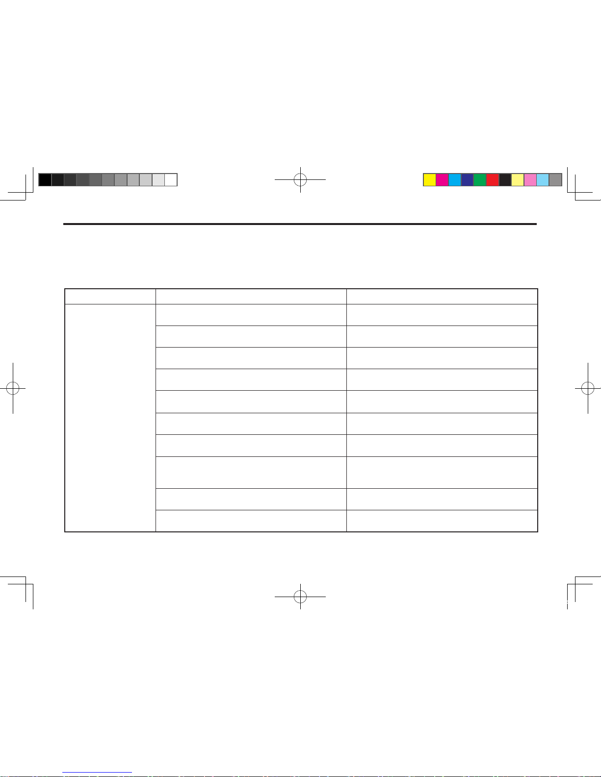
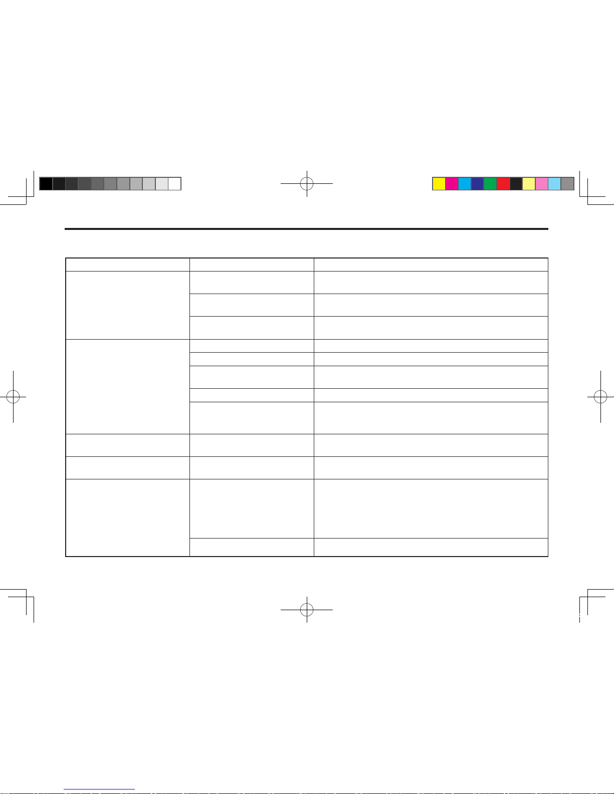
TROUBLE SHOOTING
This Trouble shooting Chart is provided for reference for possible loader operational problems. Determine the problem
that best describes the operational problem being experienced and eliminate the possible causes as listed by following
the correction procedures. For further assistance contact your dealer.
PROBLEM POSSIBLE CAUSE CORRECTION
1. Lift and Bucket cylinders inoperative.
Low hydraulic uid level.
Check and replenish hydraulic uid.
Hydraulic hoses connected improperly.
Check and correct hydraulic hose connections
.
Hydraulic hoses to/from control valve blocked.
Check for damaged (kinked) hoses, etc.
Loader control valve or tractor main relief valve
stuck open.
Check system pressure. Repair or replace relief
valve.
Low system pressure supplied from hydraulic
pump.
Check system pressure. Repair or replace pump.
Control valve linkage broken.
Inspect. Repair as required.
Quick disconnect coupler(s) are not fully
connected or "Flow check".
Check coupler connections. Replace coupler(s)
if necessary.
Hydraulic hose or tubeline blockage.
Check for evidence of damage to hoses or
tubelines that would block ow of oil between
cylinders and control valve.
Cylinder piston assembly defective (not sealing).
Check cylinders for internal leakage as described
in service section under cylinder leakage tests.
Control valve blockage.
Inspect for blockage. Disassemble valve if neces-
sary.
KL701-AU-10.indd 2 2013-03-29 오전 11:28:43
Page 47
TROUBLE SHOOTING 10-3
10
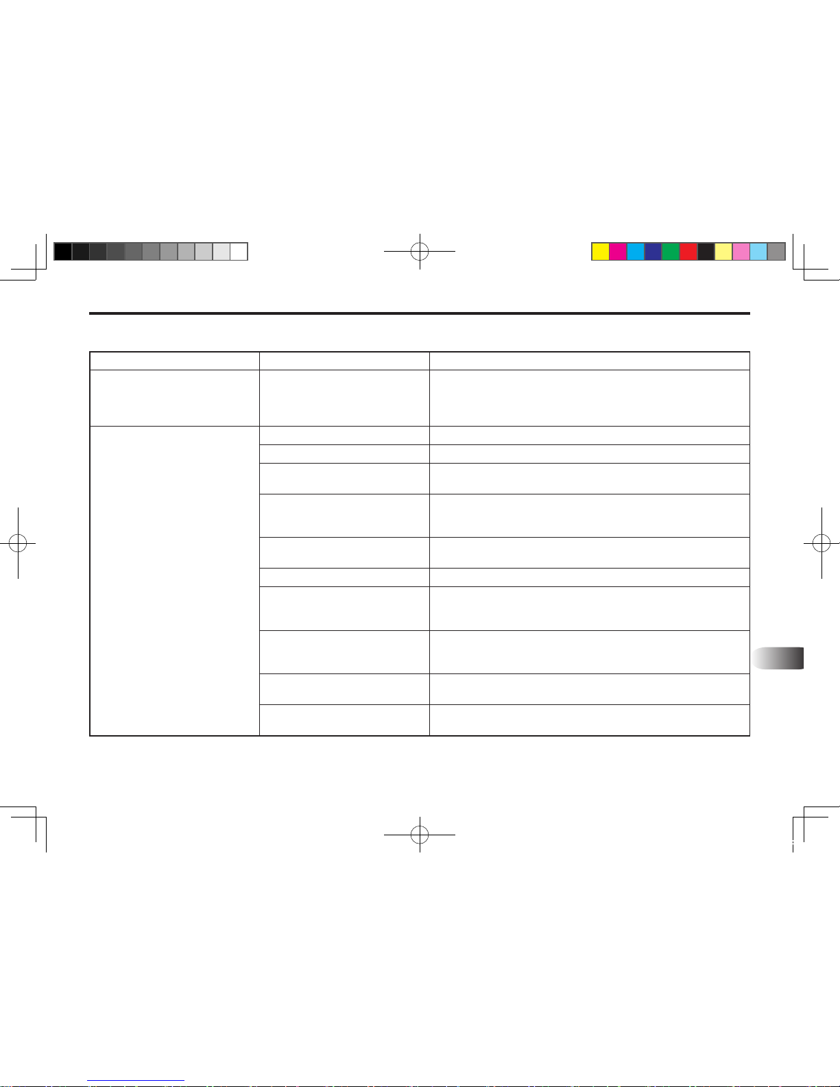
PROBLEM POSSIBLE CAUSE CORRECTION
2. Lift and/or bucket cylinders
operate in wrong direction
relative to control valve lever
position.
Hydraulic hoses connected
incorrectly.
Correct hydraulic hose connections.
3. Slow or erratic lift
Low hydraulic uid level.
Check and replenish hydraulic uid.
Cold hydraulic uid.
Allow hydraulic system to warm up to operating temperature.
Engine R.P.M. too slow (hy-
draulic pump R.P.M. too slow).
Increase engine speed to obtain satisfactory loader opera-
tion.
Excessive weight in bucket.
Material weight exceeds maxi-
mum specied loader capacity.
Reduce material load.
Control valve linkage binding/
defective.
Check control valve linkage and repair if worn/defective.
Aeration of hydraulic uid
Refer to "Aeration of Hydraulic Fluid."
Quick disconnect coupler
restriction or coupler "Flow
Checks"
Check coupler connections.
Repair or replace.
Hydraulic hose or tube-line
restriction (hoses/tube-line
kinked or pinched.)
Check hoses and tube-lines for evidence of restriction.
Lift cylinder piston assembly
leakage.
Check cylinders for leakage.
Repair as needed.
Relief valve erratic or set be-
low specications.
Check and reset relief valve setting as needed.
KL701-AU-10.indd 3 2013-03-29 오전 11:28:43
Page 48
10-4 KL701
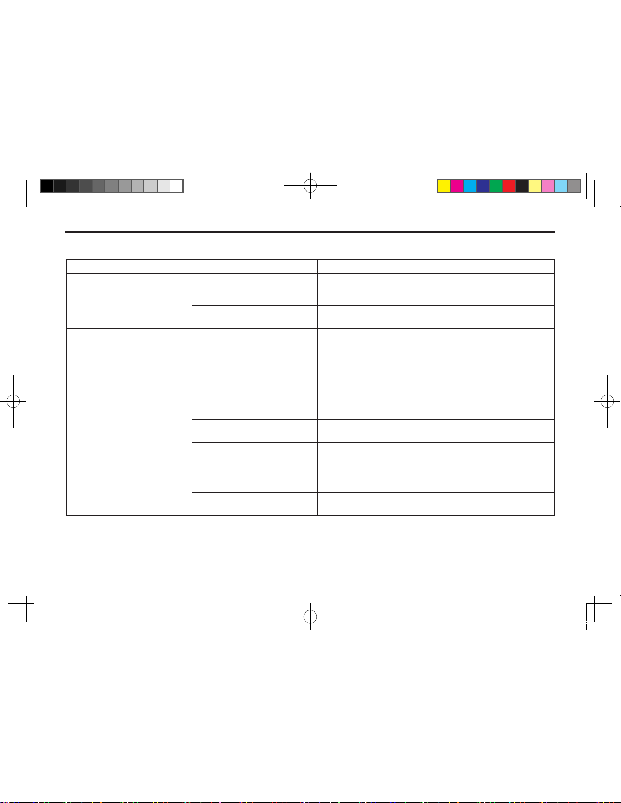
PROBLEM POSSIBLE CAUSE CORRECTION
3. Slow or erratic lift
Control valve leaking inter-
nally. (Bypassing uid within
valve.)
Replace control valve and recheck operation.
Inadequate hydraulic pump
capacity.
Refer to "Hydraulic Pump Capacity Inadequate."
4. Inadequate lifting capacity
Engine R.P.M. too slow.
Increase engine R.P.M.
Excessive load-material
weight exceeds specied
loader capacity.
Reduce Load
Relief valve setting below
specications.
Check and reset relief valve setting as needed.
Lift cylinder piston assembly
leakage.
Check cylinders for leakage.
Repair as needed.
Control valve leaking inter-
nally.
Replace control valve and recheck operation.
Hydraulic pump defective.
Refer to "Hydraulic Pump Capacity Inadequate."
5. Aeration of Hydraulic Fluid
(generally indicated by foamy
appearance of uid).
Low hydraulic uid level.
Check and rell hydraulic system to proper level.
Air leaking into suction side of
hydraulic pump.
Check for loose or defective connections between reservoir
and hydraulic pump.
Hydraulic uid foaming due to
improper hydraulic oil usage.
Refer to Tractor Operator's Manual and replace hydraulic oil
using recommended hydraulic oil.
KL701-AU-10.indd 4 2013-03-29 오전 11:28:44
Page 49
TROUBLE SHOOTING 10-5
10
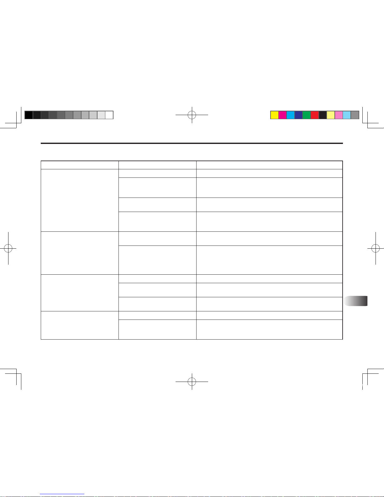
PROBLEM POSSIBLE CAUSE CORRECTION
6. System relief valve squeals.
Cold hydraulic uid.
Allow hydraulic uid to warm up to operating temperature.
Excessive load in bucket.
Weight exceeds specied
loader capacity.
Reduce load.
Relief valve setting below
specications.
Check and reset valve setting as needed.
Hydraulic hose, tube line or
quick disconnect coupler restriction.
Check for evidence of restriction in hydraulic oil ow. Repair
or replace defective components.
7. Loader drops with control
valve spool in "Centered"
position (no external oil
leakage evident.)
Note : A gradual drop over an
extended period of time is a
normal condition.
Cylinder piston assembly leak-
age.
Check cylinders for leakage.
Control valve internal leakage. Replace control valve and recheck.
8. Control valve spool(s) will not
return to centered position.
Control lever linkage binding. Determine origin of binding and repair.
Control valve spool centering
is broken.
Replace centering spring.
Control valve spool binding in
valve body spool bore.
Disassemble valve for inspection and repair.
9. External hydraulic uid
leakage.
Loose hydraulic connection. Tighten loose connections.
Defective hydraulic hose, tube
line adapter tting & tting
O-ring.
Check for origin of oil leak and replace defective parts.
KL701-AU-10.indd 5 2013-03-29 오전 11:28:44
Page 50
10-6 KL701
PROBLEM POSSIBLE CAUSE CORRECTION
9. External hydraulic uid
leakage.
Control valve O-rings defec-
tive.
Replace defective O-rings.
Control valve spool or body
damaged or worn.
Replace control valve.
Cylinder rod packing set leak-
age.
Check cylinders for leakage.
Repair as needed.
10. Hydraulic pump capacity
inadequate.
Cold hydraulic uid.
Allow hydraulic uid to warm up to operating temperature.
Engine R.P.M. too slow.
Increase engine R.P.M.
Low hydraulic uid supply.
Refer to Tractor Operator's Manual for service recommenda-
tions.
Hydraulic hose restriction.
Check for evidence of restriction in hydraulic hoses.
Hydraulic pump defective.
Refer to Tractor Operator's manual for recommended ser-
vice procedures. Replace hydraulic pump if determined to
be defective.
11. Lift cylinder rod bend when
lift cylinders extended.
Excessive shock load on lift
cylinders during transport.
Replace defective parts. Review and observe proper and
safe operational practices.
12. Bucket cutting edge wear is
uneven side to side.
Bucket is not level to ground. Check rear tire ination and adjust to level bucket to ground.
13. Bucket cutting edge wear
rate is excessive. (Wear rate
is even across full width of
bucket).
Note : Extensive use of bucket
on concrete or asphalt surfaces
will accelerate wear rate of
bucket cutting edge.
Incorrect operational prac-
tices.
Excessive down pressure
placed on bucket when being
used on hard abrasive surfaces.
Refer to operation-scraping section for correct operating pro-
cedures.
Utilize oat position.
Bucket wear pads worn.
Replace wear pads.
KL701-AU-10.indd 6 2013-03-29 오전 11:28:44
Page 51

11
11. HYDRAULIC SYSTEM
HYDRAULIC SYSTEM SCHEMATIC ..................................................... 11-2
AUXILIARY HYDRAULIC VALVE PACKAGE .............................................................. 11-2
KL701-AU-11.indd 1 2013-03-29 오전 11:28:59
Page 52
11-2 KL701
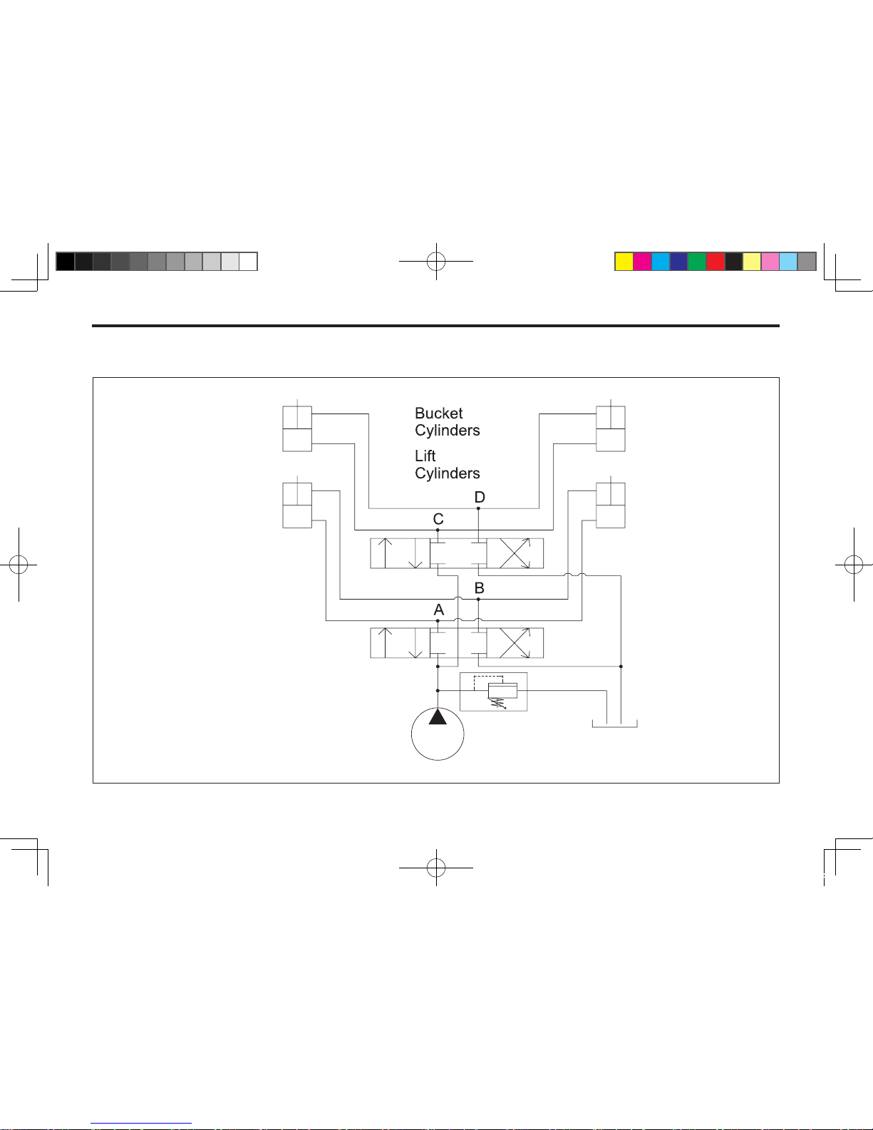
HYDRAULIC SYSTEM SCHEMATIC
AUXILIARY HYDRAULIC VALVE PACKAGE
601OB01A
A : Lift cylinder extend
B : Lift cylinder retract
C : Bucket cylinder extend
D : Bucket cylinder retract
KL701-AU-11.indd 2 2013-03-29 오전 11:28:59
Page 53

12
12. TORQUE TIGHTENING CHARTS
TORQUE TIGHTENING CHART 1 .........................................................12-2
TORQUE TIGHTENING CHART 2 .........................................................12-3
KL701-AU-12.indd 1 2013-03-29 오전 11:29:14
Page 54
12-2 KL701
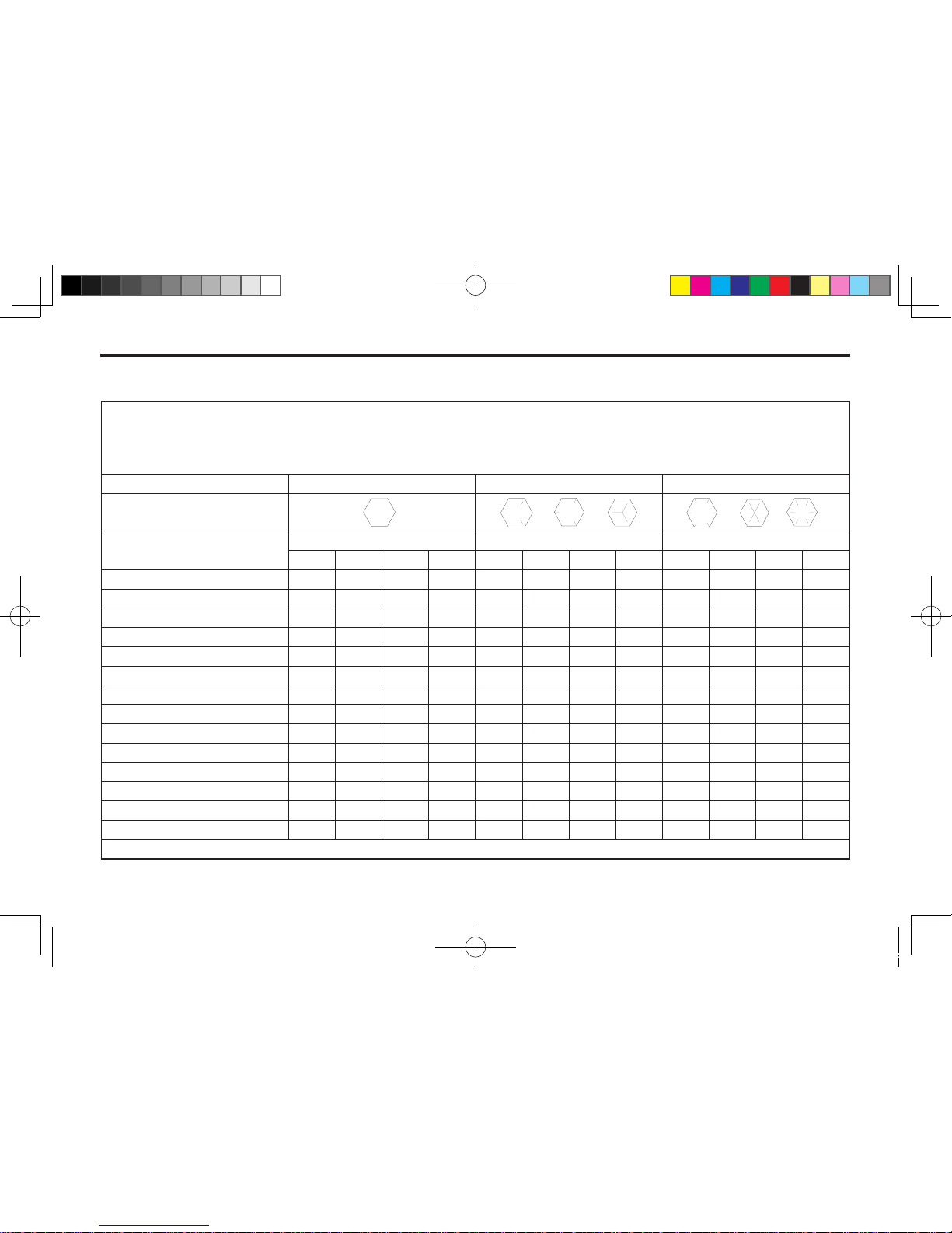
TORQUE TIGHTENING CHART 1
SAE FASTENER TORQUE CHART
Note :Usethesetorques,unlessspecialtorquesarespecied.ValuesareforUNCandUNFthreadfasteners,platedorunplated
asreceivedfromsupplier.Fastenerscanbedryorlubricatedwithnormalengineoil.
Valuesdonotapplyifgraphite,moly-disulphideorotherextremepressurelubricantisused.
SAE Grade 2 5 8
★
Boltheadidentication
(See note 1)
Bolt Size
LB FT LB FT LB FT
Min. Max. Min. Max. Min. Max. Min. Max. Min. Max. Min. Max.
1/4 5 6 7 8 9 11 12 15 12 15 16 20
5/16 10 12 14 16 17 20.5 23 28 24 29 33 39
3/8 20 23 27 31 35 42 48 57 45 54 61 73
7/16 30 35 41 47 54 64 73 87 70 84 95 114
1/2 45 52 61 70 80 96 109 130 110 132 149 179
9/16 65 75 88 102 110 132 149 179 160 192 217 260
5/8 95 105 129 142 150 180 203 244 220 264 298 358
3/4 150 185 203 251 270 324 366 439 380 456 515 618
7/8 160 200 217 271 400 480 542 651 600 720 814 976
1 250 300 339 406 580 696 787 944 900 1080 1220 1464
1 1/8 800 880 1085 1193 1280 1440 1736 1953
1 1/4 1120 1240 1519 1681 1820 2000 2468 2712
1 3/8 1460 1680 1980 2278 2380 2720 3227 3688
1 1/2 1940 2200 2631 2983 3160 3560 4285 4827
Note :Boltheadidenticationmarksaspergrade.Manufacturingmarkswillvary.*ThicknutsmustbeusedwithGrade8bolts.
KL701-AU-12.indd 2 2013-03-29 오전 11:29:15
Page 55
12
TORQUETIGHTENINGCHART 12-3
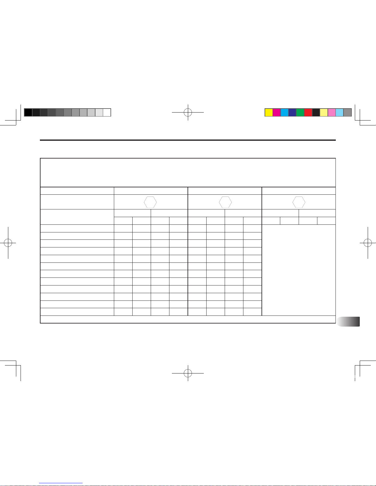
METRIC FASTENER (ISO) TORQUE CHART
Note :Usethesetorques,unlessspecialtorquesarespecied.ValuesareforUNCandUNFthreadfasteners,platedorunplated
asreceivedfromsupplier.Fastenerscanbedryorlubricatedwithnormalengineoil.
Valuesdonotapplyifgraphite,moly-disulphideorotherextremepressurelubricantisused.
ISO Class No. 8.8 10.9 12.9
Boltheadidentication
(See note 1)
Bolt Size
Nm LB FT Nm LB FT Nm LB FT
Min. Max. Min. Max. Min. Max. Min. Max. Min. Max. Min. Max.
M4 3 4 2 3 4 5 3 4 Because of thelowductility
ofthesefasteners, thetorque
ra nge is tobedetermined
individuallyforeachapplication.
Asageneralrule,thetorque
rang es specif ied for g ra de
10.9fasteners canbeused
satisfactorilyon12.9fasteners.
*M14isnotapreferredsize.
M5 6.5 8 5 6 9.5 11 7 8
M6 10.5 12 8 9 15 17.5 11 13
M8 26 31 19 23 37 43 27 32
M10 52 61 38 45 73 87 54 64
M12 90 107 66 79 125 150 93 112
*M14 144 172 106 127 200 245 149 179
M16 217 271 160 200 310 380 230 280
M20 434 515 320 380 610 730 450 540
M24 675 815 500 600 1050 1275 780 940
M30 1250 1500 920 1100 2000 2400 1470 1770
M36 2175 2600 1600 1950 1120 1240 1519
Note :Boltheadidenticationmarksaspergrade.Manufacturingmarkswillvary.
TORQUE TIGHTENING CHART 2
8.8 10.9 12.9
KL701-AU-12.indd 3 2013-03-29 오전 11:29:16
Page 56

MEMO
............................................................................................................................................................................
............................................................................................................................................................................
............................................................................................................................................................................
............................................................................................................................................................................
............................................................................................................................................................................
............................................................................................................................................................................
............................................................................................................................................................................
............................................................................................................................................................................
............................................................................................................................................................................
............................................................................................................................................................................
............................................................................................................................................................................
............................................................................................................................................................................
............................................................................................................................................................................
............................................................................................................................................................................
............................................................................................................................................................................
............................................................................................................................................................................
KL701-AU-12.indd 4 2013-03-29 오전 11:29:16
Page 57

13
GENERAL INFORMATION ....................................................................13-2
ILLUSTRATIONS .........................................................................................................13-2
BUCKET, QUICK ATTACHMENT
................................................................................13-4
4IN1 BUCKET ASSEMBLY
..........................................................................................13-6
FRONT GRILL ASSEMBLY (OPTIONAL)
..................................................................13-10
MOUNTING FRAME ASSEMBLY
..............................................................................13-12
BOOM ASSEMBLY
....................................................................................................13-14
BOOM HYDRAULIC ASSEMBLY
..............................................................................13-18
BOOM HYDRAULIC ASSEMBLY (4IN1 STD)
...........................................................13-22
AUXILIARY HYDRAULIC DEVICE (OPTION)
...........................................................13-28
BOOM CYLINDER ASSEMBLY-LH
...........................................................................13-32
BOOM CYLINDER ASSEMBLY-RH
...........................................................................13-34
BUCKET CYLINDER ASSEMBLY
.............................................................................13-36
DECALS ................................................................................................ 13-38
13. PART ILLUSTRATIONS
KL701-AU-13.indd 1 2013-05-10 오후 4:33:40
Page 58
13-2 KL701
GENERAL INFORMATION
ILLUSTRATIONS
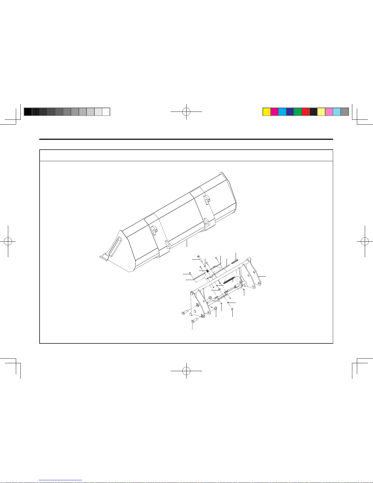
All parts are illustrated in "exploded views" which show the individual parts in their normal relationship to each other.
Reference numbers are used in the illustrations. These numbers correspond to those in the "Reference Number".
column and are followed by the quantity required and description.
DIRECTIONAL REFERENCE
"Right hand" and "left hand" sides are determined by standing at the rear of the unit and facing in the direction of
forward travel.
PARTS ORDER
Orders must give the complete description, correct part number, the total amount required, the product model, all the
necessary serial numbers, the method of shipment and the shipping address.
INSTRUCTIONS
1. GROUP NAME : Detail classication name for parts.
2. SECTION NAME : Classication name for parts.
3. COMPONENTS : The components of an assembly are identied by a bracket.
4. NO.: Reference numbers are assigned to parts in the gure.
KL701-AU-13.indd 2 2013-05-10 오후 4:33:40
Page 59
PART ILLUSTRATIONS 13-3
13
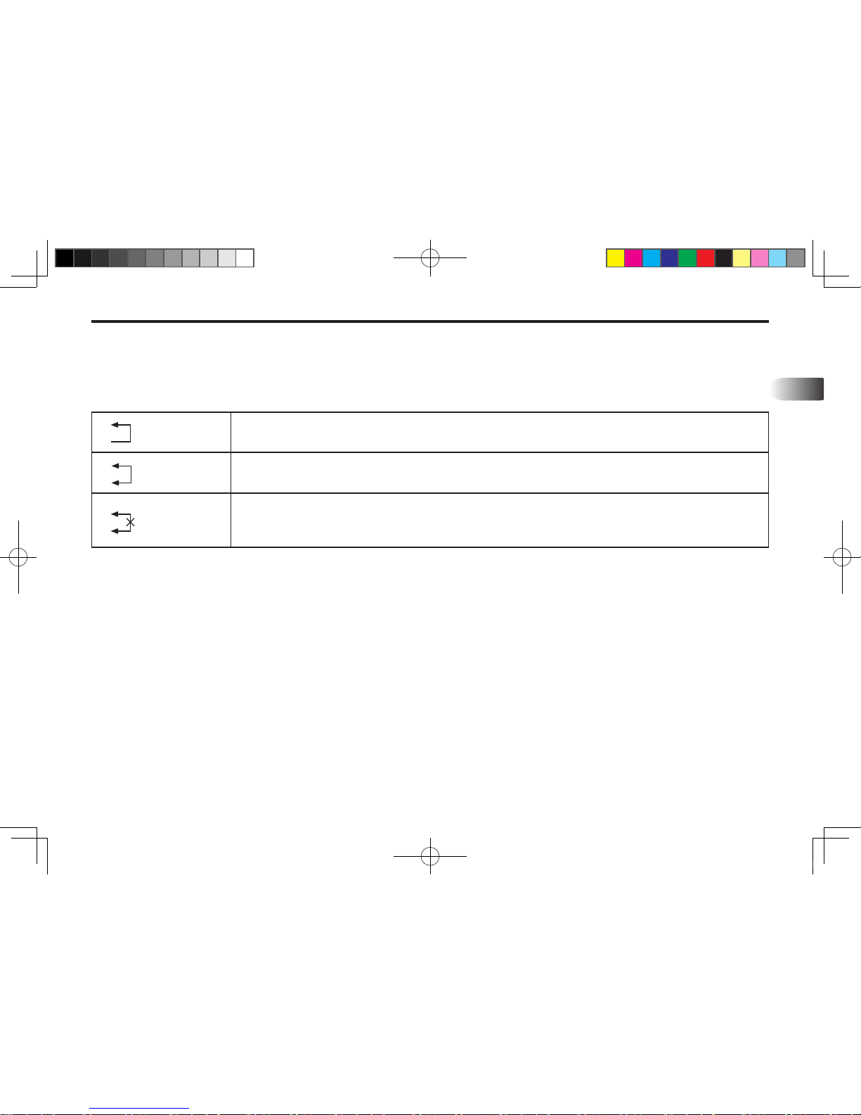
Indicates that a new part can be used instead of an old part when you order this part, please
order new part.
Indicates that either parts can be used.
Indicates that a part has a serial number break.
When you order this part, please order a part according to the serial number of the loader.
INTERCHANGEABILITY
: Indicates the interchangeabillty of parts due to design change.
★Due to our policy of continuously improving products, The information contained herein is subject to change without
notice.
~4265-99999
5265-00001~
KL701-AU-13.indd 3 2013-05-10 오후 4:33:40
Page 60
13-4 KL701
BUCKET, QUICK ATTACHMENT
701OD01C
18
19
15
11
7
16
10
13
4
6
14
9
8
1
2
3
13
17
12
5
KL701-AU-13.indd 4 2013-05-10 오후 4:33:41
Page 61
PART ILLUSTRATIONS 13-5
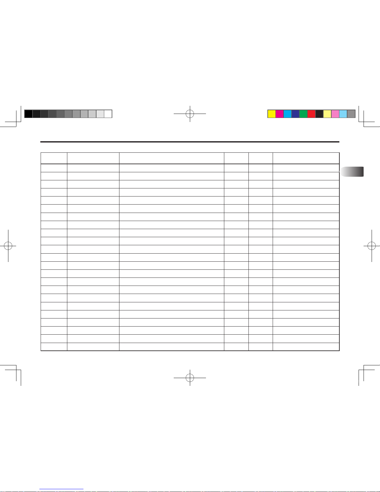
REF. NO PART. NO DESCRIPTION QTY I.C REMARK
13
0
1
2
3
4
5
6
7
8
9
10
11
12
13
14
15
16
17
18
19
FTQU6-10000
FTQU6-10100
FTQU2-10200
FTQU2-10300
FTQU2-10301
14132-20185
14232-36032
14224-28181
FTQU2-11003
10191-M1606-90
10261-M1606
1021N-M1606
10316-M1600
10321-M1600
10191-M1004-35
1021N-M1004
802G0-T1900
FTBU3-82300-01
14131-30155-N
1021M-M3006
Quick Attachment Ass`y - Euro Hitch Type(No.1~16)
Quick Attach Frame
Lever W.A-Quick
Link W.A-Quick
Link-Quick
Pin W.A-Quick
Spring
Spring
Grip-Rubber
Hex Bolt, M16-P2.0 90L
Hex Bolt, M16-P2.0
Nut-Selock, M16-P2.0
Washer-Spring, M16
Washer-Plain, M16
Hex Bolt, M10-P1.5 35L
Nut-Selock, M10-P1.5
Nipple, Grease, 1/8"
Bucket W.A - ISO (82")
Pin, Ø30-155L
Nut-Selock, M30-P2.0
1
1
1
1
1
2
1
1
1
1
1
1
1
2
4
4
2
1
4
4
KL701-AU-13.indd 5 2013-05-10 오후 4:33:41
Page 62
13-6 KL701
10
9
8
12
15
17
16
13
11
12
15
7
7
18
18
14
14
19
20
21
22
23
5
4
2
1
6
3
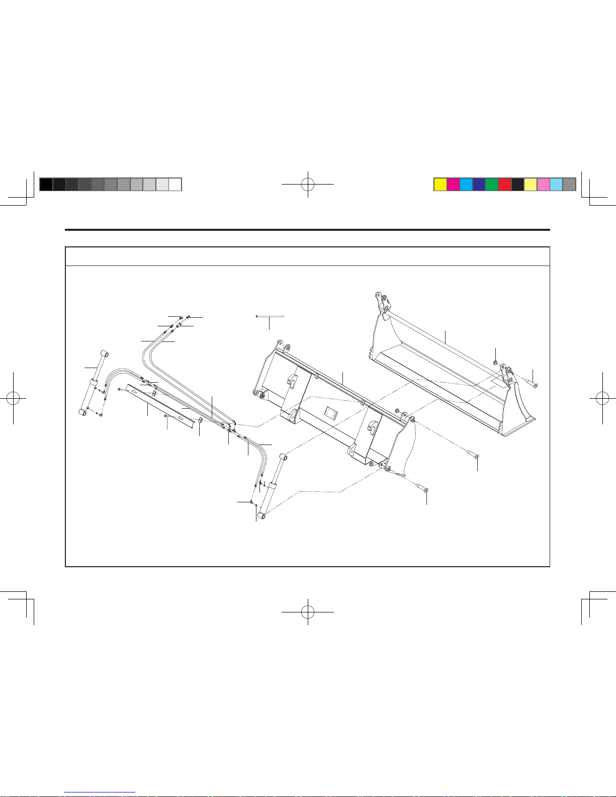
4IN1 BUCKET ASSEMBLY
701OD09B
KL701-AU-13.indd 6 2013-05-10 오후 4:33:42
Page 63
PART ILLUSTRATIONS 13-7
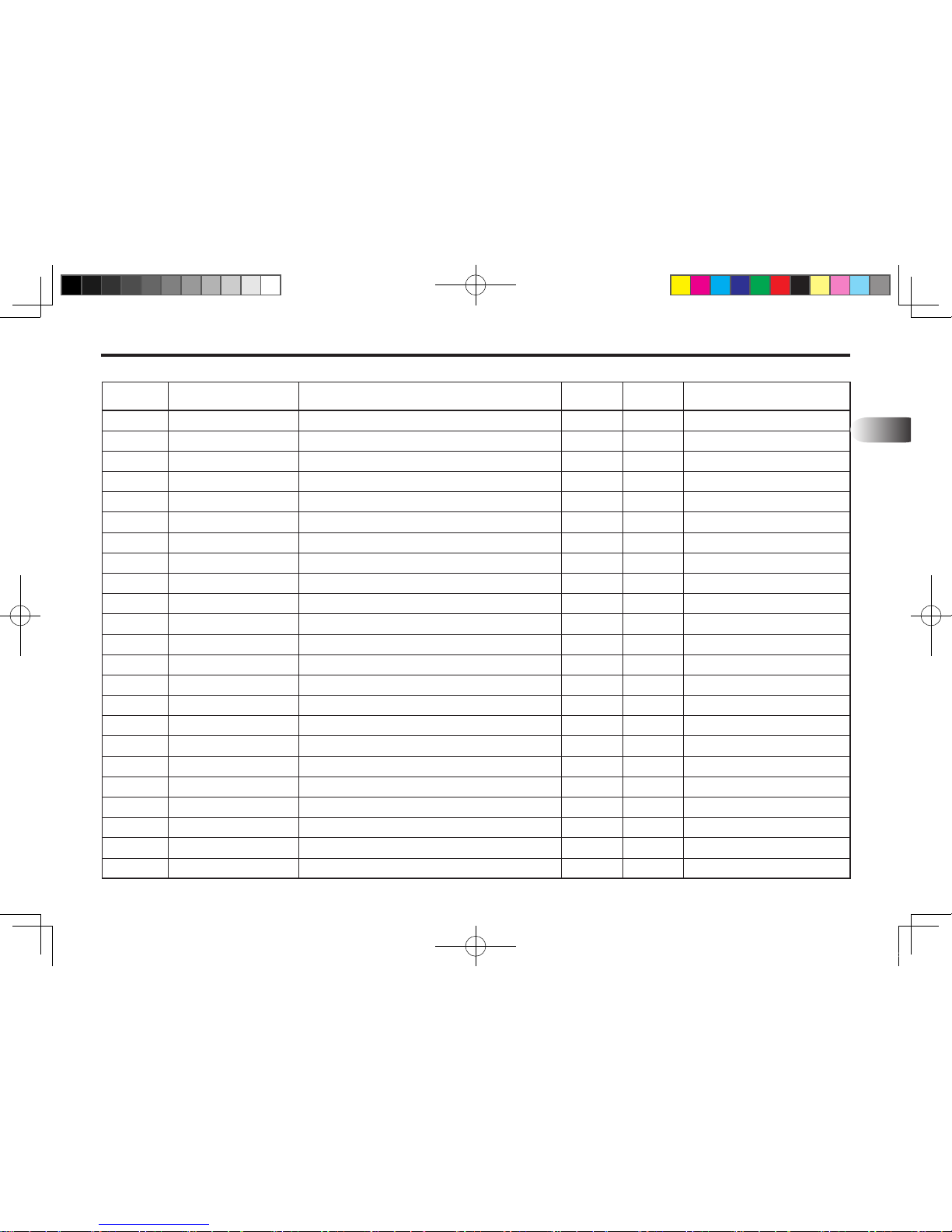
REF. NO PART. NO DESCRIPTION QTY I.C REMARK
13
0
1
2
3
4
5
6
7
8
9
10
11
12
13
14
15
16
17
18
19
20
21
22
ZTBU5-7800S-01
ZTBU5-7810N
ZTBU5-78200-01
14124-25110-N
14124-25138-N
14124-25122-N
1021M-M2404
ZTBU5-H700
FTF40-62102
ZTBU5-72301
1012S-M0803-35
226505
802L2-P46F9-42
802T2-F94F9-40
802N2-F94F9-40
81300-0P014
80620-01002
80620-01003
80620-07011
80420-T1130
80410-T1130
8043K-01100
8044K-01100
4in1 Bucket Ass'y, 78" (NO. 1~23)
Front Bucket W.A, 78", V-hump Type
Rear Bucket W.A-ISO Euro, 78"
Pin W.A, Ø25-110L
Pin W.A, Ø25-138L
Pin W.A, Ø25-122L
Nut-Selock, M24-P1.5
Pipe Ass’y, Ø12
Clamp
Cover, Pipe
Sem’s Bolt, M8-P1.25 35L
Cylinder, 30x50x415L(ST180)
Nipple, 3/4-16UNF, Hose x PF3/8, O-ring 90˚
Nipple, 3/4-16UNF, T-Hose
Nipple, 3/4-16UNF, Hose x 3/4-16UNF, Hose
O-ring, P14
Hose, 4(3/4-16UNF)-4(3/4-16UNF) 350L(3/8)
Hose, 4(3/4-16UNF)-4(3/4-16UNF) 550L(3/8)
Hose, 904(3/4-16UNF)-1(PT1/2) 1700L(3/8)
Quifk Coupler, PT1/2" Female
Quifk Coupler, PT1/2" Male
Dust Plug, 1/2" Black Male
Dust Cap, 1/2" Black Female
1
1
1
2
2
2
6
2
2
1
2
2
4
2
2
4
2
2
2
1
1
1
1
KL701-AU-13.indd 7 2013-05-10 오후 4:33:42
Page 64
13-8 KL701
10
9
8
12
15
17
16
13
11
12
15
7
7
18
18
14
14
19
20
21
22
23
5
4
2
1
6
3
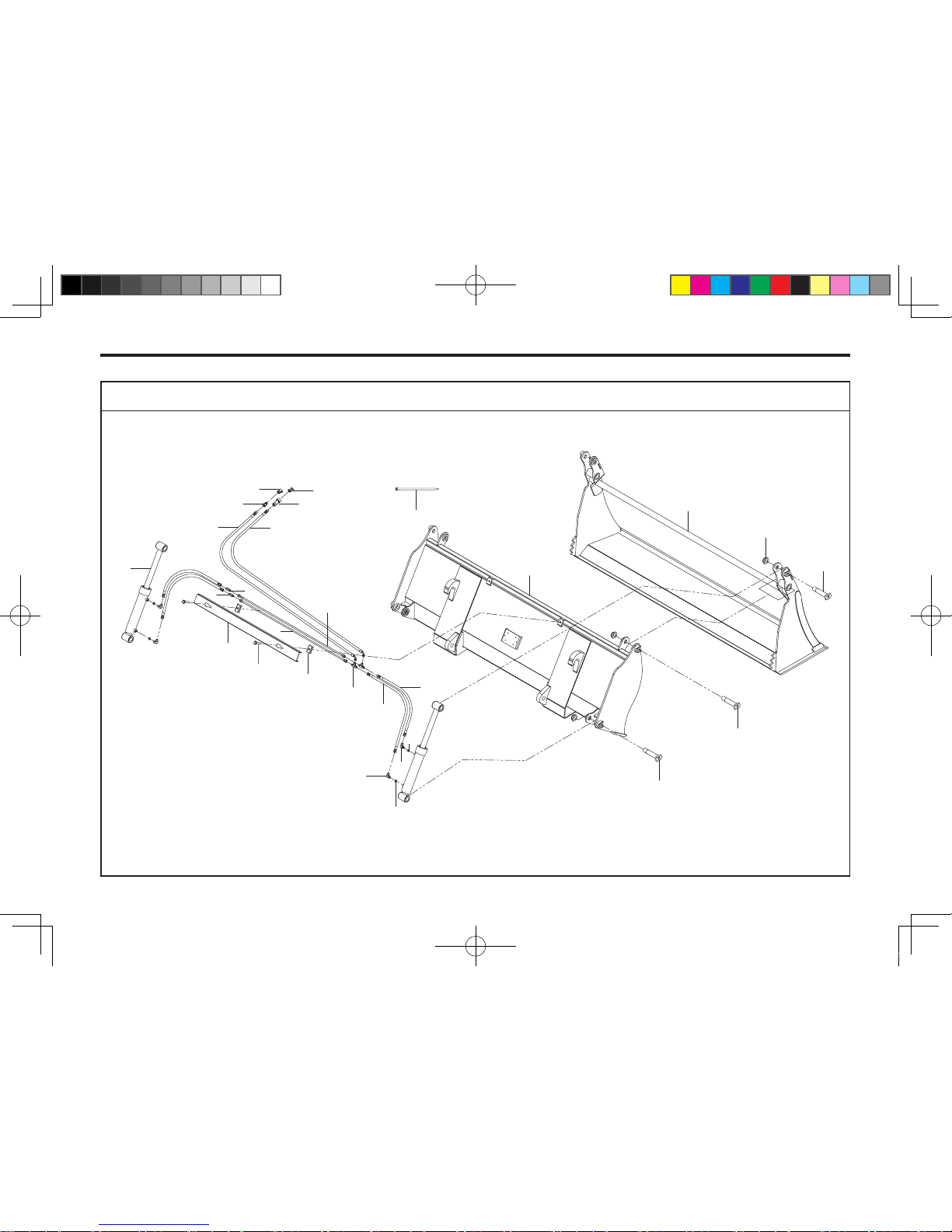
4IN1 BUCKET ASSEMBLY
701OD09B
KL701-AU-13.indd 8 2013-05-10 오후 4:33:42
Page 65
PART ILLUSTRATIONS 13-9
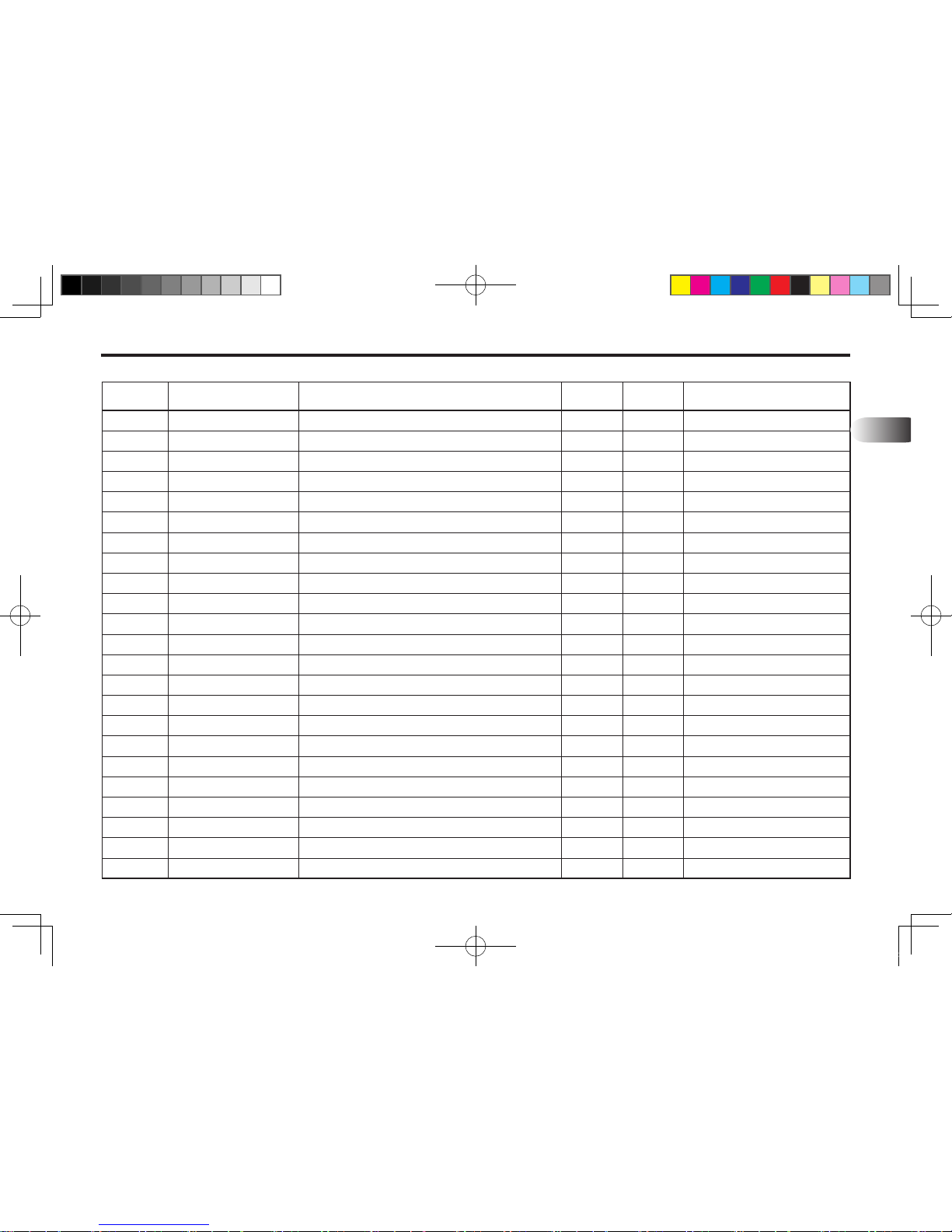
REF. NO PART. NO DESCRIPTION QTY I.C REMARK
13
23 50120-M270K Cable Tie, 270mm Black 3
KL701-AU-13.indd 9 2013-05-10 오후 4:33:42
Page 66
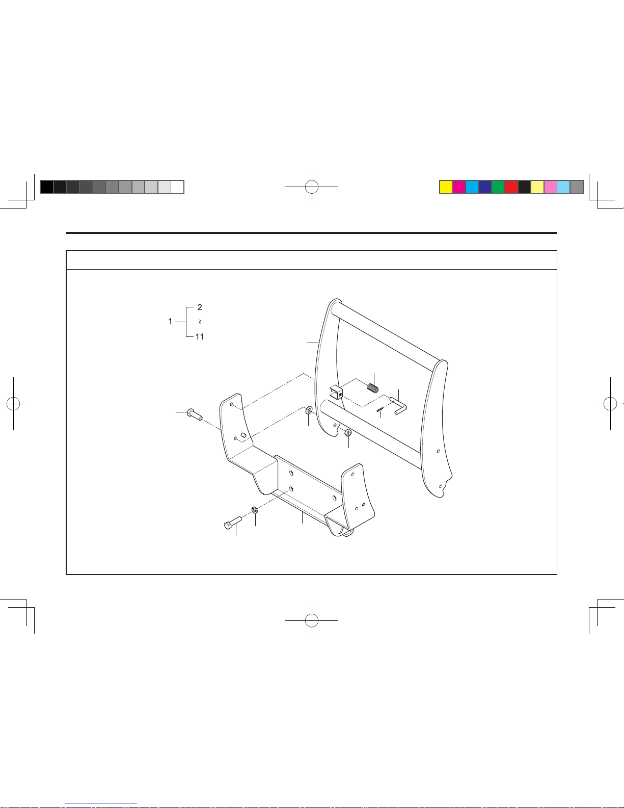
13-10 KL701
FRONT GRILL ASSEMBLY (OPTIONAL)
601OD03A
9
8
7
3
4
2
10
5
6
11
KL701-AU-13.indd 10 2013-05-10 오후 4:33:42
Page 67
PART ILLUSTRATIONS 13-11
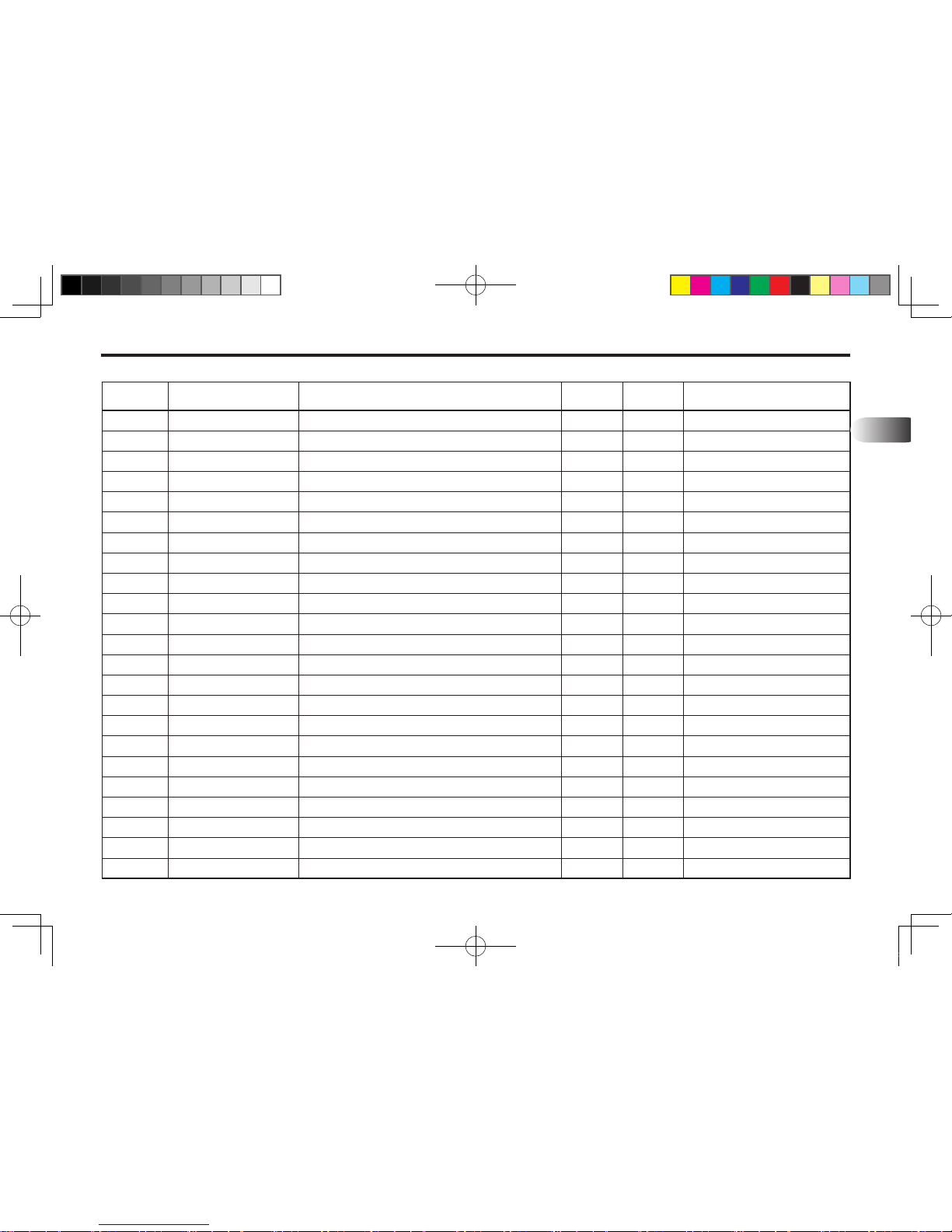
REF. NO PART. NO DESCRIPTION QTY I.C REMARK
13
1
2
3
4
5
6
7
8
9
10
11
FT116-G1000
FT116-11700
FT613-11600-02
10191-M1205-35
10321-M1200
1021N-M1205
14116-12086-01
LK01-0203
14031-04040
10191-M1604-40
10316-M1600
Grill Kit, NO.2~11
Grill, Outer
Grill, Inner
Hex-Bolt, M12-1.75P 35L
Plain-Washer, M12
Hex-Nut Lock, M12-1.75P
Pin, Ø12
Spring, Ø1.5
Spring-Pin, Ø4
Hex-Bolt, M16-1.5P 40L
Spring-Washer, M16
1
1
1
2
2
2
2
2
2
4
4
KL701-AU-13.indd 11 2013-05-10 오후 4:33:43
Page 68
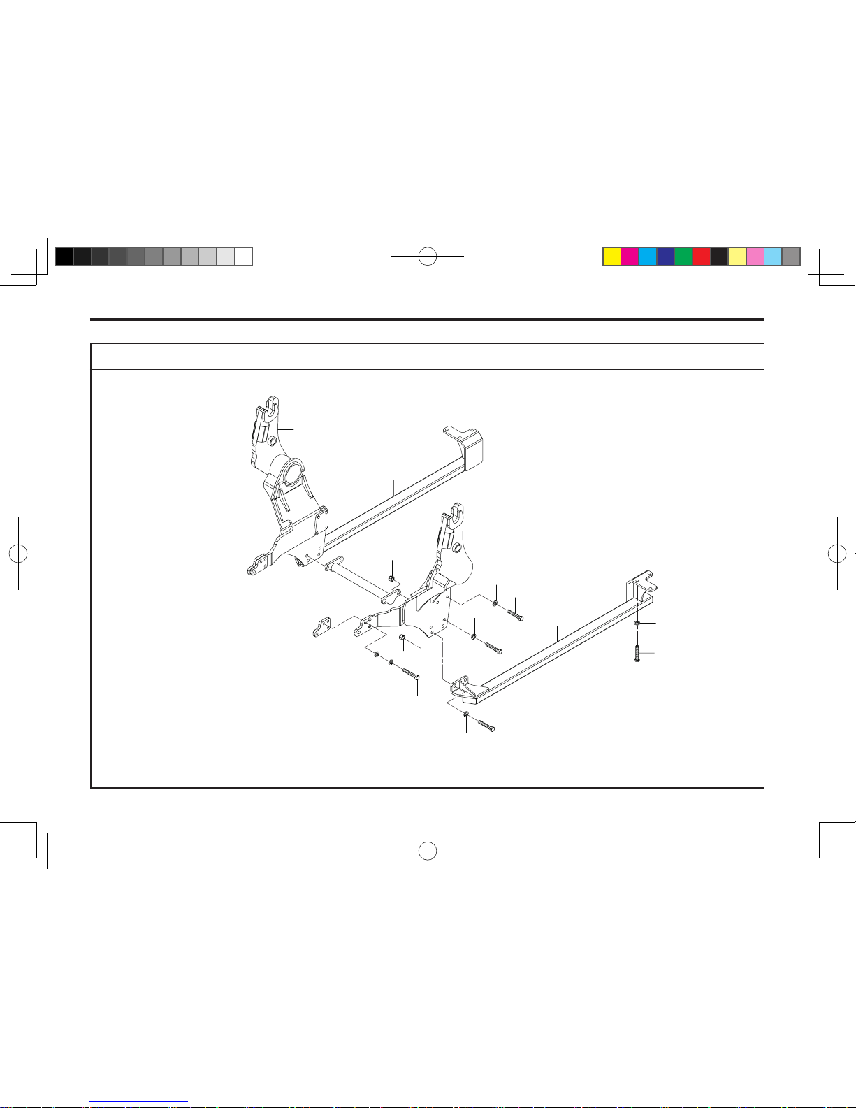
13-12 KL701
MOUNTING FRAME ASSEMBLY
4
3
9
7
12
11
5
13
6
10
9
7
13
12
11
1
2
8
9
701OD01A
KL701-AU-13.indd 12 2013-05-10 오후 4:33:43
Page 69
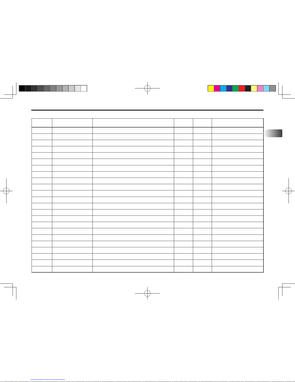
PART ILLUSTRATIONS 13-13
REF. NO PART. NO DESCRIPTION QTY I.C REMARK
13
1
2
3
4
5
6
7
8
9
10
11
12
13
FT117-11100
FT117-11200
FT116-11300
FT116-11400
FT116-11500
FT116-11801
10191-M1404-60
10191-M1404-50
10316-M1400
10321-M1400
10191-M1606-50
10316-M1600
10261-M1606
Mounting Frame W.A, LH
Mounting Frame W.A, RH
Rear Frame W.A, LH
Rear Frame W.A, RH
Cross Bar
Space
Hex-Bolt-HT, M14 x P1.5 x L60
Hex-Bolt-HT, M14 x P1.5 x L50
Washer-Spring, M14
Washer-Plain, M14
Hex-Bolt-HT, M16 x P2.0 x L50
Washer-Spring, M16
Hex-Nut-HT, M16 x P2.0
1
1
1
1
1
2
16
6
22
8
8
8
8
KL701-AU-13.indd 13 2013-05-10 오후 4:33:43
Page 70
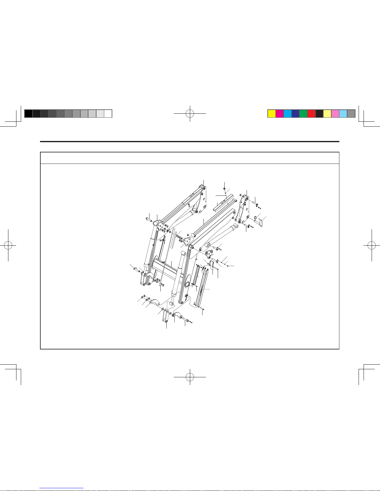
13-14 KL701
BOOM ASSEMBLY
701OD08B
8
10
19
22
11
9
21
20
32
28
27
26
12
31
1
23
24
25
7
6
14
17
16
13
33
4
35
18
22
34
3
2
15
29
30
36
37
40
38
39
40
KL701-AU-13.indd 14 2013-05-10 오후 4:33:44
Page 71
PART ILLUSTRATIONS 13-15
REF. NO PART. NO DESCRIPTION QTY I.C REMARK
13
1
2
3
4
5
6
7
8
9
10
11
12
13
14
15
16
17
18
19
20
21
22
23
FTF66-11100-01
FTF34-53100
FTF66-11410
FTF66-11420
FTF35-52101
FTF39-20100-02
FTF35-55100-01
FTF66-11600
FTF66-11603
FTF66-11604
FTE44-11605
FTF66-11200
FTF66-11300
FTF39-11101
FTF66-11015
FTF66-70100
FTF66-70200
10191-M1406-A0
10191-M1406-B0
10191-M1205-40
1021N-M1205
1021N-M1406
10121-M0803-FM
Boom W.A
Link W.A
Link W.A, LH
Link W.A, RH
Link
Link W.A-LEVEL
Safety Bar W.A
Stand W.A
Stand-Lock
Foot Plate
Stand Spring
Link W.A, LH
Link W.A, RH
Plate
Plain-Washer
Bar Gauge Long, Ø12-1360L
Bar Gauge Short, Ø12.7-360L
Hex-Bolt, M14-P2.0-100L
Hex-Bolt, M14-P2.0-110L
Hex-Bolt, M12-P1.75-40L
Nut-Self Lock, M12-P1.75
Nut-Self Lock, M14-P2.0
Bolt Ass'y, M8-P1.25
1
1
1
1
2
2
2
2
2
2
2
1
1
2
4
1
1
2
2
4
4
4
2
KL701-AU-13.indd 15 2013-05-10 오후 4:33:44
Page 72
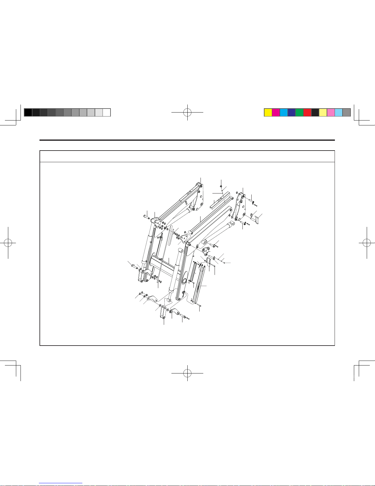
13-16 KL701
BOOM ASSEMBLY
701OD08B
8
10
19
22
11
9
21
20
32
28
27
26
12
31
1
23
24
25
7
6
14
17
16
13
33
4
35
18
22
34
3
2
15
29
30
36
37
40
38
39
40
KL701-AU-13.indd 16 2013-05-10 오후 4:33:44
Page 73
PART ILLUSTRATIONS 13-17
REF. NO PART. NO DESCRIPTION QTY I.C REMARK
13
24
25
26
27
28
29
30
31
32
33
34
35
36
37
38
39
40
10211-M0803
10321-M0800
1019N-M1004-25
10316-M1000
10321-M1000
FTF66-11029
1301C-03000
14136-30111-N
14136-30133-N
14137-30140-N
14136-30139-N
14137-30146-N
FT117-20100
FT117-20200
FT117-20300
14021-10000
14136-30145-N
Hex-Nut, M8 x P1.25
Washer-Plain, M8
Nyloc Bolt, M10-P1.5-25L
Washer-Spring, M10
Washer-Plain, M10
Washer-Pin, Ø30.5-Ø50-3.2T
Snap-Ring, C-Type, Ø30
Pin, Ø30-111L
Pin, Ø30-133L
Pin, Ø30-140L
Pin, Ø30-139L
Pin, Ø30-146L
Top Post W.A, LH
Top Post W.A, RH
Pin, Ø34-164.5L
Ring-Pin, Ø10
Pin, Ø30-145L
2
2
18
18
18
10
18
2
5
1
3
1
1
1
2
2
6
KL701-AU-13.indd 17 2013-05-10 오후 4:33:44
Page 74
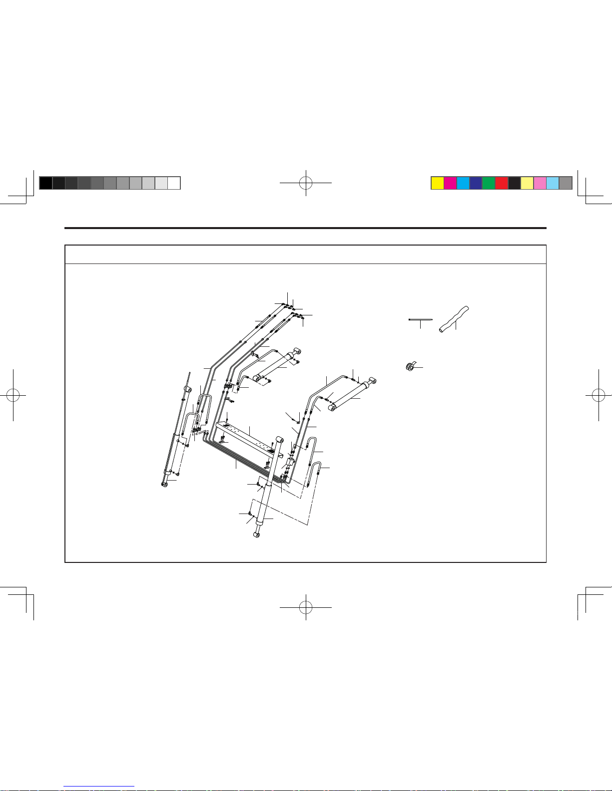
13-18 KL701
BOOM HYDRAULIC ASSEMBLY
701OD07A
27
29
28
31
32
30
33
34
35
3
24
23
11
1
36
12
17
6
10
7
18
5
25
22
9
9
10
20
10
9
10
9
4
17
5
26
21
2
8
3
23
23
14
13
19
16
15
KL701-AU-13.indd 18 2013-05-10 오후 4:33:45
Page 75
PART ILLUSTRATIONS 13-19
REF. NO PART. NO DESCRIPTION QTY I.C REMARK
13
0
1
2
3
4
5
6
7
8
9
10
11
12
13
14
15
16
17
18
19
20
21
22
FTF66-H0000
22D003
22D004
22D001
FTF66-H0101
1012S-M0803-35
801T1-50000
802N2-P46F9-42
802H1-F94F9-40
802L2-P46F9-42
81301-BP014
FTF39-HP100
FTF39-HP200
FTF39-HP300
FTF39-HP400
FTF39-HP500
FTF39-HP600
FTF39-HP700
FTF39-HP800
80620-01037
80620-03031
80620-01027
80620-03011
Hydraulic piping Kit, NO.1~26
Boom Cylinder Ass'y LH, Ø40-Ø70-905L (ST572)
Boom Cylinder Ass'y RH, Ø40-Ø70-905L (ST572)
Bucket Cylinder Ass'y, Ø35-Ø70-1080L (ST405)
Cover
Sem's Bolt, M8-P1.25-35L
Valve, Relife
Nipple, PF3/8, O-Ring x 3/4-16UNF, Hose
Nipple, 3/4-16UNF, Hose H-Type
Nipple, 3/4-16UNF, Hose x PF3/8, O-Ring 90˚
O-Ring, 1BP14
Pipe Ass’y
Pipe Ass’y
Pipe Ass’y
Pipe Ass’y
Pipe Ass’y
Pipe Ass’y
Pipe Ass’y
Pipe Ass’y
Hyd Hose, 4(3/4-16UNF)-4(3/4-16UNF) 1050L(3/8)
Hyd Hose, 4(3/4-16UNF)-2(3/4-16UNF) 1100L(3/8)
Hyd Hose, 4(3/4-16UNF)-4(3/4-16UNF) 450L(3/8)
Hyd Hose, 4(3/4-16UNF)-2(3/4-16UNF) 450L(3/8)
1
1
2
1
11
1
4
4
8
12
1
1
1
1
1
1
2
1
1
1
1
1
KL701-AU-13.indd 19 2013-05-10 오후 4:33:45
Page 76
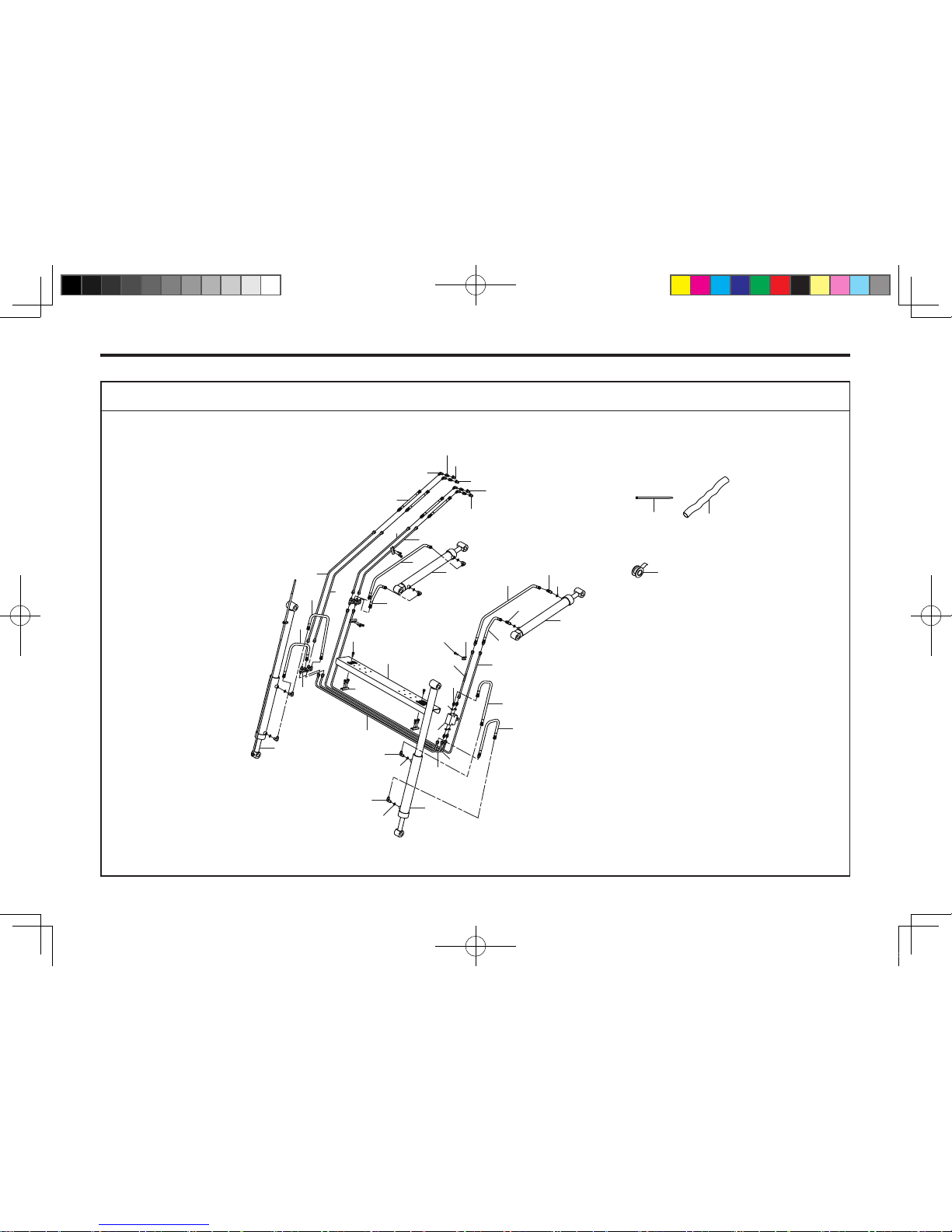
13-20 KL701
BOOM HYDRAULIC ASSEMBLY
701OD07A
27
29
28
31
32
30
33
34
35
3
24
23
11
1
36
12
17
6
10
7
18
5
25
22
9
9
10
20
10
9
10
9
4
17
5
26
21
2
8
3
23
23
14
13
19
16
15
KL701-AU-13.indd 20 2013-05-10 오후 4:33:46
Page 77
PART ILLUSTRATIONS 13-21
REF. NO PART. NO DESCRIPTION QTY I.C REMARK
13
23
24
25
26
27
28
29
30
31
32
33
34
35
36
80620-01026
80620-03010
FTF40-62102
FTF40-62101
80620-03039
802L2-T63F9-40
80410-T1130
8044R-01100
8044B-01100
8044W-01100
8044Y-01100
50135-1500K
50120-M270K
99400-00001
Hyd Hose, 4(3/4-16UNF)-4(3/4-16UNF) 850L(3/8)
Hyd Hose, 4(3/4-16UNF)-2(3/4-16UNF) 850L(3/8)
Clamp
Clamp
Hyd Hose, 4(3/4-16UNF)-2(3/4-16UNF)-1700L(3/8)
Nipple, 3/4-16UNF, Hose x PT1/2 90˚
Quick Coupler, PT1/2" Male
Dust Cap, 1/2" Red Female
Dust Cap, 1/2" Blue Female
Dust Cap, 1/2" White Female
Dust Cap, 1/2" Yellow Female
Webbing, 90x1500mm
Cable Tie, 270mm Black
Teon Tape
3
1
1
4
4
4
4
1
1
1
1
1
2
1
KL701-AU-13.indd 21 2013-05-10 오후 4:33:46
Page 78
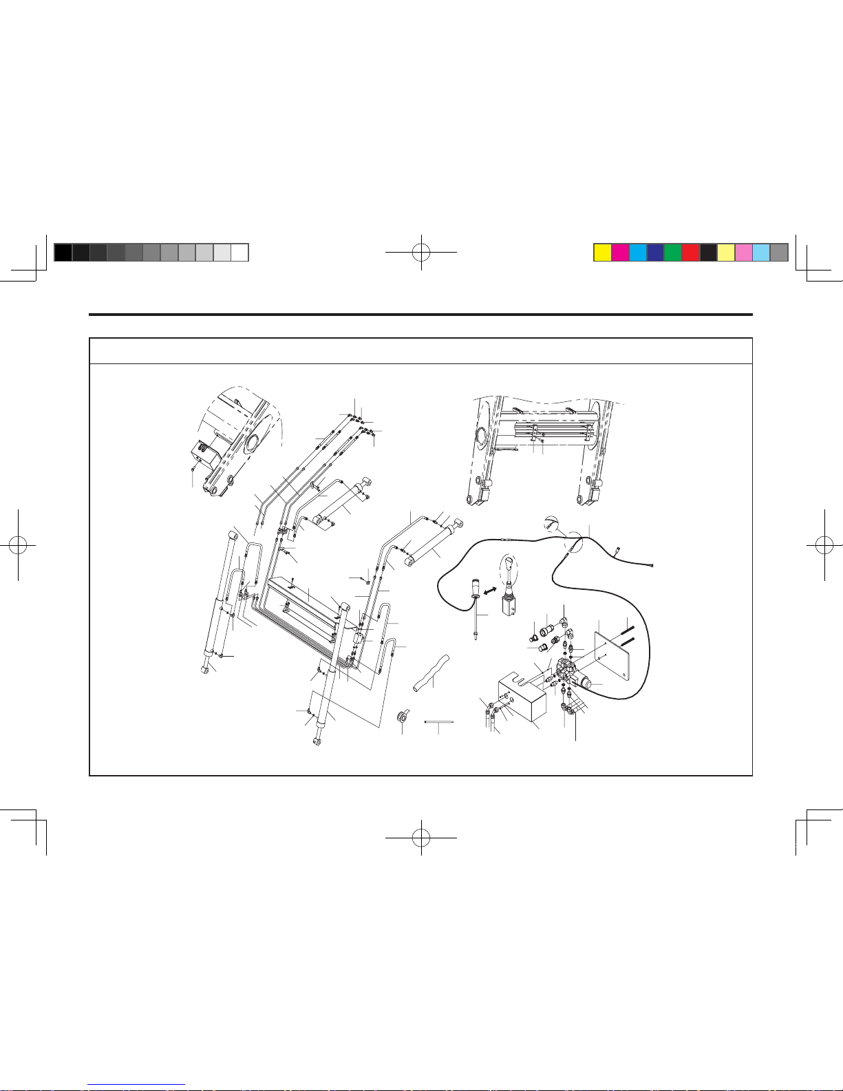
13-22 KL701
51
52
32
30
29
31
33
43
42
28
36-2
36-1
35-2
35-1
27
34
34
27
26
40
41
39
43
42
connect to
N
o. 35
-2 hose
connect to
N
o. 35
-1 hose
to 36-2
to 36-1
1
21
10
22
23
9
5
11
16
16
3
9
8
8
3
8
8
4
4
37
25
6
17
4
24
8
9
8
19
20
2
18
4
22
22
7
12
13
14
15
45
31
46
48
49
47
50
25
38
4
53
44
-
+
54
55
BOOM HYDRAULIC ASSEMBLY (4IN1 STD)
701OD10B
KL701-AU-13.indd 22 2013-05-10 오후 4:33:47
Page 79
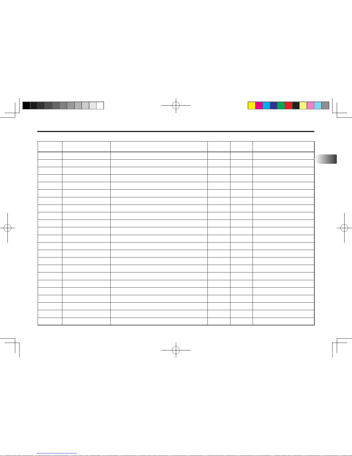
PART ILLUSTRATIONS 13-23
REF. NO PART. NO DESCRIPTION QTY I.C REMARK
13
1
2
3
4
5
6
7
8
9
10
11
12
13
14
15
16
17
18
19
20
21
22
23
22D003
22D004
22D001
1012S-M0803-35
801T1-50000
802N2-P46F9-42
802H1-F94F9-40
802L2-P46F9-42
81301-BP014
FTF39-HP100
FTF39-HP200
FTF66-HP100
FTF66-HP200
FTF39-HP500
FTF39-HP600
FTF41-HP700
FTF39-HP800
80620-01037
80620-03031
80620-01027
80620-03011
80620-01026
80620-03010
Boom Cylinder Ass'y LH, Ø40-Ø70-905L (ST572)
Boom Cylinder Ass'y RH, Ø40-Ø70-905L (ST572)
Bucket Cylinder Ass'y, Ø35-Ø70-1080L (ST405)
Bolt-Sem's, M8x1.25P 35L
Valve, Relife
Nipple, PF3/8,O-Ring x 3/4-16UNF
Nipple, H-TYPE 3/4-16UNF, Hose
Nipple, PF3/8, O-Ring x 3/4-16UNF, Hose 90˚
O-Ring, 1BP14
Pipe Ass'y
Pipe Ass'y
Pipe Ass'y
Pipe Ass'y
Pipe Ass'y
Pipe Ass'y
Pipe Ass'y
Pipe Ass'y
Hyd Hose, 4(3/4-16UNF)x4(3/4-16UNF) 1050L(3/8)
Hyd Hose, 4(3/4-16UNF)x2(3/4-16UNF) 1100L(3/8)
Hyd Hose, 4(3/4-16UNF)x4(3/4-16UNF) 450L(3/8)
Hyd Hose, 4(3/4-16UNF)x2(3/4-16UNF) 450L(3/8)
Hyd Hose, 4(3/4-16UNF)x4(3/4-16UNF) 850L(3/8)
Hyd Hose, 4(3/4-16UNF)x2(3/4-16UNF) 850L(3/8)
1
1
2
15
1
4
4
8
12
1
1
1
1
1
1
2
1
1
1
1
1
3
1
KL701-AU-13.indd 23 2013-05-10 오후 4:33:47
Page 80
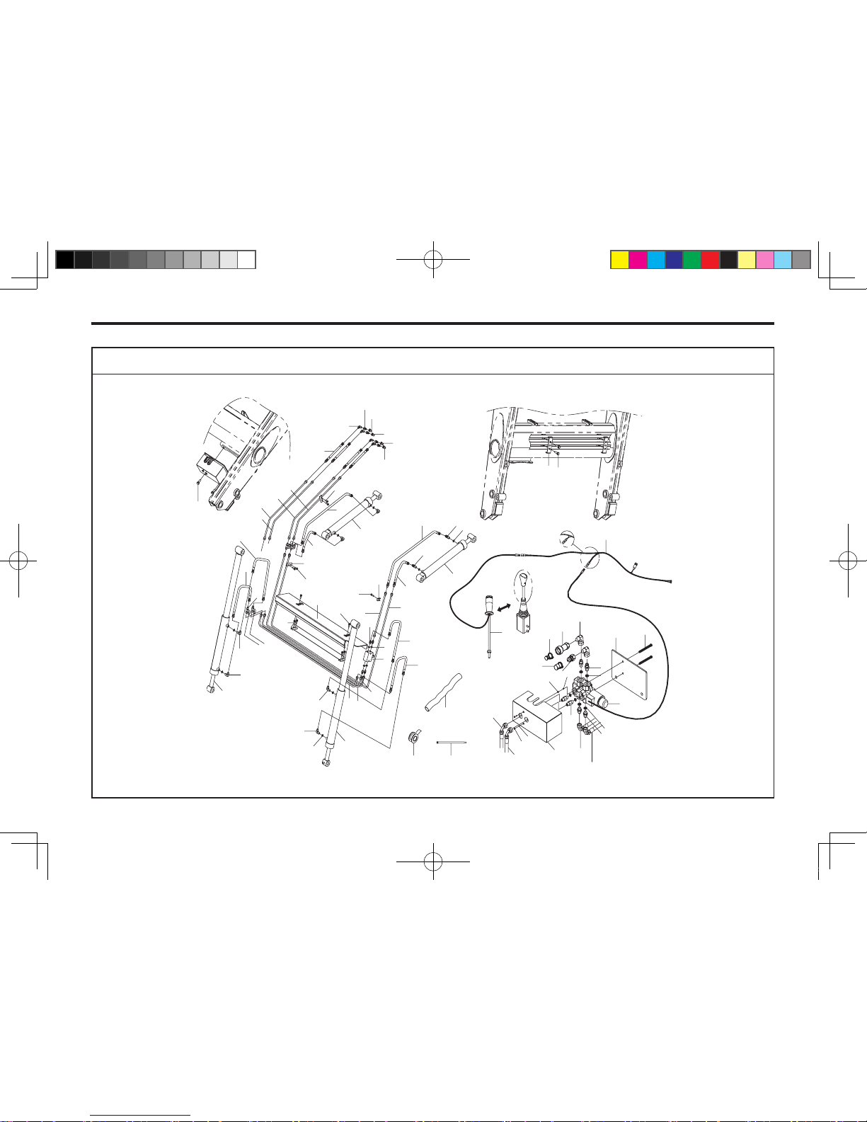
13-24 KL701
51
52
32
30
29
31
33
43
42
28
36-2
36-1
35-2
35-1
27
34
34
27
26
40
41
39
43
42
connect to
N
o. 35
-2 hose
connect to
N
o. 35
-1 hose
to 36-2
to 36-1
1
21
10
22
23
9
5
11
16
16
3
9
8
8
3
8
8
4
4
37
25
6
17
4
24
8
9
8
19
20
2
18
4
22
22
7
12
13
14
15
45
31
46
48
49
47
50
25
38
4
53
44
-
+
54
55
BOOM HYDRAULIC ASSEMBLY (4IN1 STD)
701OD10B
KL701-AU-13.indd 24 2013-05-10 오후 4:33:47
Page 81
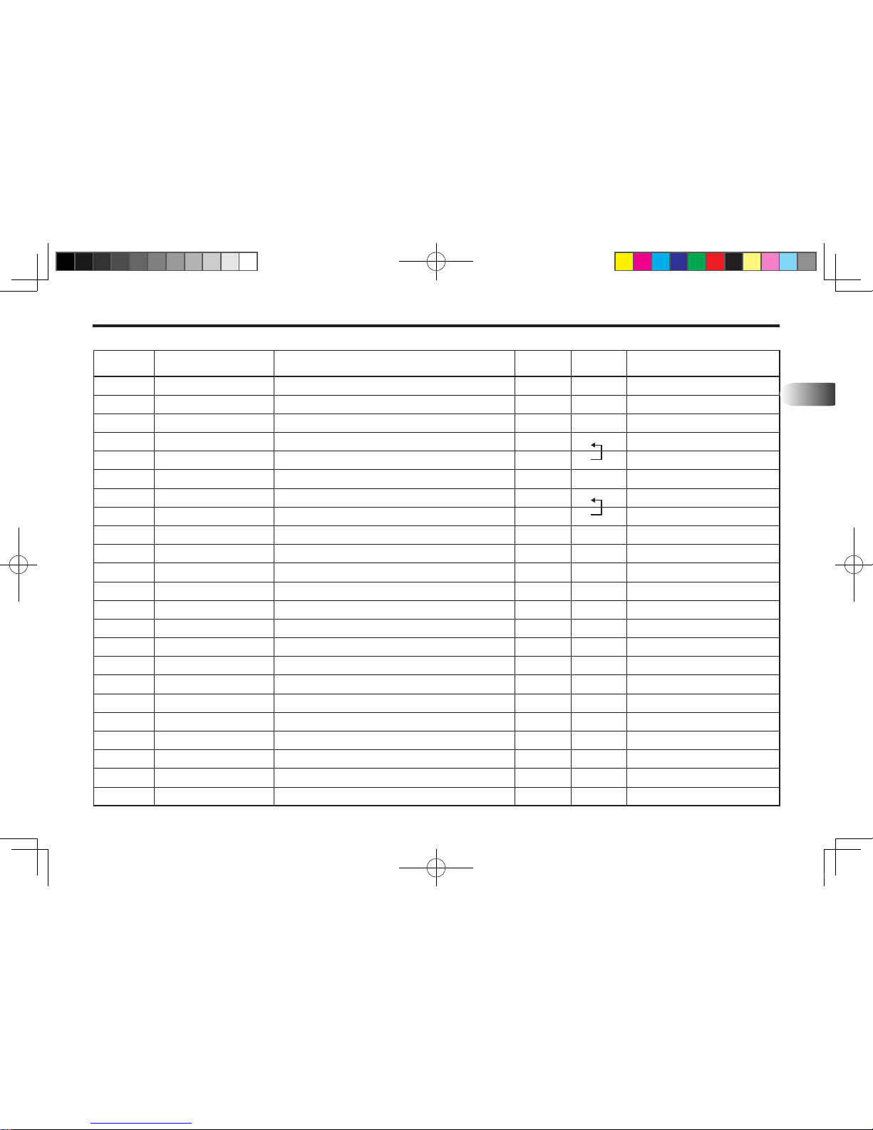
PART ILLUSTRATIONS 13-25
REF. NO PART. NO DESCRIPTION QTY I.C REMARK
13
24
25
26
27
27
28
29
29
30
31
32
33
34
35
36
37
38
39
40
41
42
43
44
FTF40-62102
FTF40-62101
801Z1-02000
802N0-T46P4-61
802N2-P46F9-41
802N2-P46F9-4M
802N2-F94T6-3S
802N2-F94T6-3S
80420-T1130
80410-T1130
8043K-01100
8044K-01100
103C0-C0330
80620-23008
80620-08010
FTF66-H0104
FTE44-H0036
FTF66-H0102
FTF66-H0103
10121-M0602-C0
10316-M0600
10211-M0602
1012S-M1004-25
Clamp
Clamp
Valve, DUKIN
Nipple, PF3/8, Copper×3/8
Nipple, PF3/8, Copper×3/4-16UNF, Hose
Nipple, PF3/8 Copper x 3/4-16UNF (69L)
Nipple, PF1/4(O-Ring)×1/2-20UNF(9O˚ Elbow)
Nipple, PF1/4(O-Ring)×1/2-20UNF(9O˚ Swivel)
Quick Coupler, PT1/2 Female
Quick Coupler, PT1/2 Male
Dust Plug, 1/2" Male Black
Dust Cap, 1/2, Black
Washer-Copper, 3/8"
Hyd Hose, 904(3/4-16UNF)x454(3/4-16UNF)1070L(3/8) 180˚
Hyd Hose, 904(3/4-16UNF)x2(3/4-16UNF) 1500L(3/8)
Cover, Pipe
Clamp
Cover, Valve
Plate, Solenoid Valve
Hex-Bolt, M6xP1.0-120L
Washer-Spring, M10
Hex-Nut, M6x1.0P
Bolt-Sem's, M10x1.5P 25L
1
4
1
4
4
2
2
2
1
5
1
1
6
2
2
1
2
1
1
2
4
4
2
13.04.11~
Wrong spec
KL701-AU-13.indd 25 2013-05-10 오후 4:33:48
Page 82
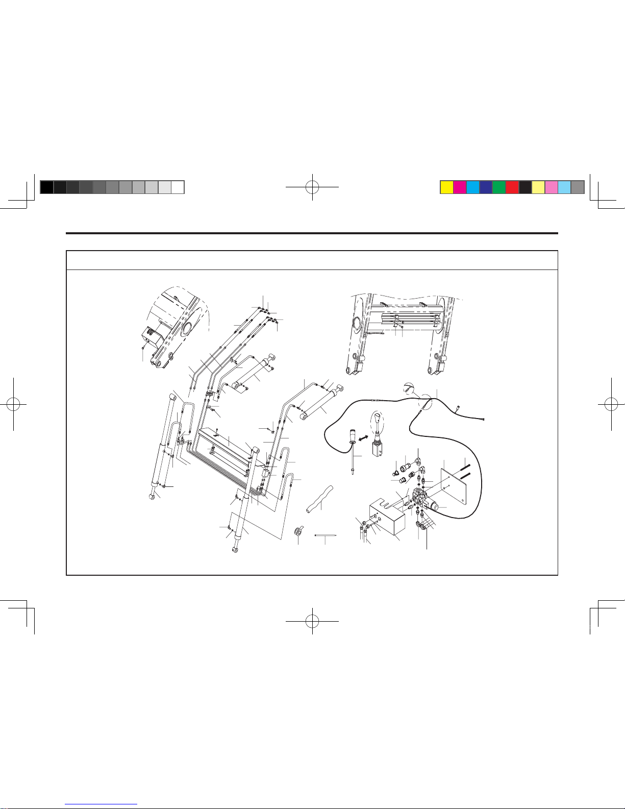
13-26 KL701
51
52
32
30
29
31
33
43
42
28
36-2
36-1
35-2
35-1
27
34
34
27
26
40
41
39
43
42
connect to
N
o. 35
-2 hose
connect to
N
o. 35
-1 hose
to 36-2
to 36-1
1
21
10
22
23
9
5
11
16
16
3
9
8
8
3
8
8
4
4
37
25
6
17
4
24
8
9
8
19
20
2
18
4
22
22
7
12
13
14
15
45
31
46
48
49
47
50
25
38
4
53
44
-
+
54
55
BOOM HYDRAULIC ASSEMBLY (4IN1 STD)
701OD10B
KL701-AU-13.indd 26 2013-05-10 오후 4:33:48
Page 83
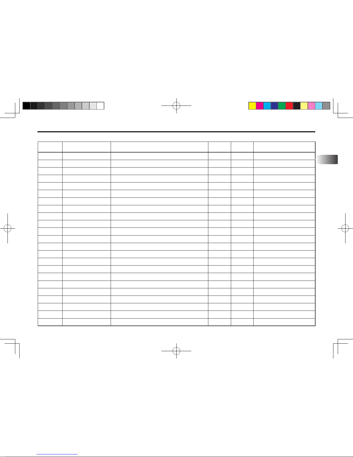
PART ILLUSTRATIONS 13-27
REF. NO PART. NO DESCRIPTION QTY I.C REMARK
13
45
46
47
48
49
50
51
52
53
54
55
80620-03039
802L2-T63F9-
408044R-01100
8044B-01100
8044W-01100
8044Y-01100
50135-1500K
50120-M270K
99400-00001
FT303-91000
801W1-80J60
Hyd Hose, 4(3/4-16UNF)x2(3/4-16UNF) 1700L(3/8)
Nipple, PT1/2x3/4-16UNF(9O˚ELBOW)
Dust Cap, 1/2" Red Male
Dust Cap, 1/2" Blue Male
Dust Cap, 1/2" White Male
Dust Cap, 1/2" Yellow Male
Webbing, 90x1500L
Cable Tie, 270mm Black
Tefron Tape
Haness Ass'y
Electric Lever
4
4
1
1
1
1
1
2
1
1
1
KL701-AU-13.indd 27 2013-05-10 오후 4:33:48
Page 84
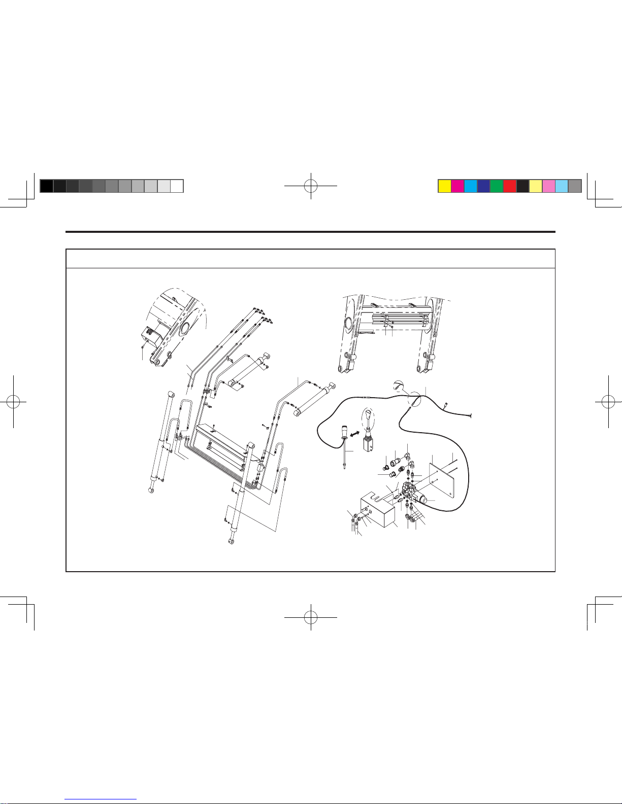
13-28 KL701
10
8
7
9
11
21
20
6
16
15
14
13
5
12
12
5
4
18
19
17
21
20
co
n
nect to No. 14
hose
connect
t
o No.
13 ho
se
3
1
2
24
23
to 16
to 15
22
-
+
24
25
AUXILIARY HYDRAULIC DEVICE (OPTION)
701OD11B
KL701-AU-13.indd 28 2013-05-10 오후 4:33:49
Page 85
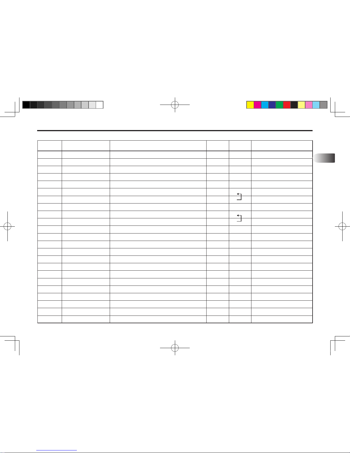
PART ILLUSTRATIONS 13-29
REF. NO PART. NO DESCRIPTION QTY I.C REMARK
13
1
2
3
4
5
6
6
7
8
8
9
10
11
12
13
14
15
16
17
18
19
20
21
1012S-M0803-35
FTF66-HP100
FTF66-HP200
80620-03031
801Z1-02000
802N0-T46P4-61
802N2-P46F9-41
802N2-P46F9-4M
802N2-F94T6-3S
802N2-F94T6-3S
80420-T1130
80410-T1130
8043K-01100
8044K-01100
103C0-C0330
80620-23008
80620-08010
FTF66-H0104
FTE44-H0036
FTF66-H0102
FTF66-H0103
10121-M0602-C0
10316-M0600
Bolt-Sem's, M8x1.25P 35L
Pipe Ass'y
Pipe Ass'y
Hyd Hose, 4(3/4-16UNF)x2(3/4-16UNF) 1100L(3/8)
Valve, DUKIN
Nipple, PF3/8 Copper x PT3/8
Nipple, PF3/8, Copper×3/4-16UNF, Hose
Nipple, PF3/8 Copper×3/4-16UNF (69L)
Nipple, PF1/4(O-Ring)×1/2-20UNF(9O˚ Elbow)
Nipple, PF1/4(O-Ring)×1/2-20UNF(9O˚ Swivel)
Quick Coupler, PT1/2 Female
Quick Coupler, PT1/2 Male
Dust Plug, 1/2" Male Black
Dust Cap, 1/2, Black
Washer-Copper, 3/8"
Hyd Hose, 904(3/4-16UNF)x454(3/4-16UNF)1070L(3/8) 180˚
Hyd Hose, 904(3/4-16UNF)x2(3/4-16UNF) 1500L(3/8)
Cover, Pipe
Clamp
Cover, Valve
Plate, Solenoid Valve
Hex-Bolt, M6xP1.0-120L
Washer-Spring, M10
4
1
1
1
1
4
4
2
2
2
1
1
1
1
6
2
2
1
2
1
1
2
4
13.04.11~
Wrong spec
KL701-AU-13.indd 29 2013-05-10 오후 4:33:49
Page 86
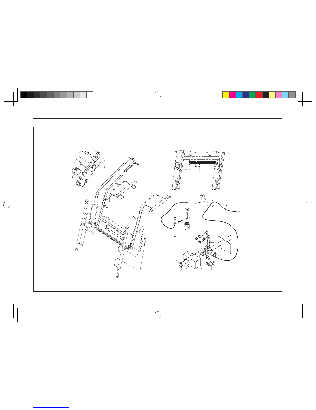
13-30 KL701
10
8
7
9
11
21
20
6
16
15
14
13
5
12
12
5
4
18
19
17
21
20
co
n
nect to No. 14
hose
connect
t
o No.
13 ho
se
3
1
2
24
23
to 16
to 15
22
-
+
24
25
701OD11B
AUXILIARY HYDRAULIC DEVICE (OPTION)
KL701-AU-13.indd 30 2013-05-10 오후 4:33:50
Page 87
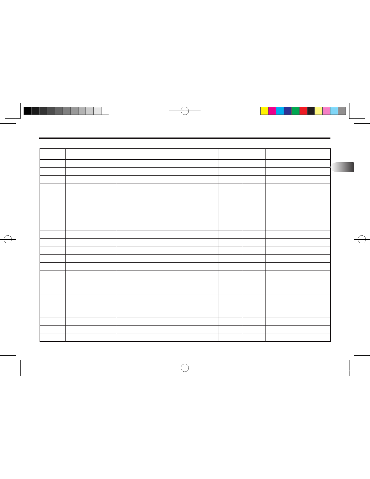
PART ILLUSTRATIONS 13-31
REF. NO PART. NO DESCRIPTION QTY I.C REMARK
13
22
23
24
25
10211-M0602
1012S-M1004-25
FT303-91000
801W1-80J60
Hex-Nut, M6x1.0P
Bolt-Sem's, M10x1.5P 25L
Haness Ass`y
Electric Lever
4
2
1
1
KL701-AU-13.indd 31 2013-05-10 오후 4:33:50
Page 88
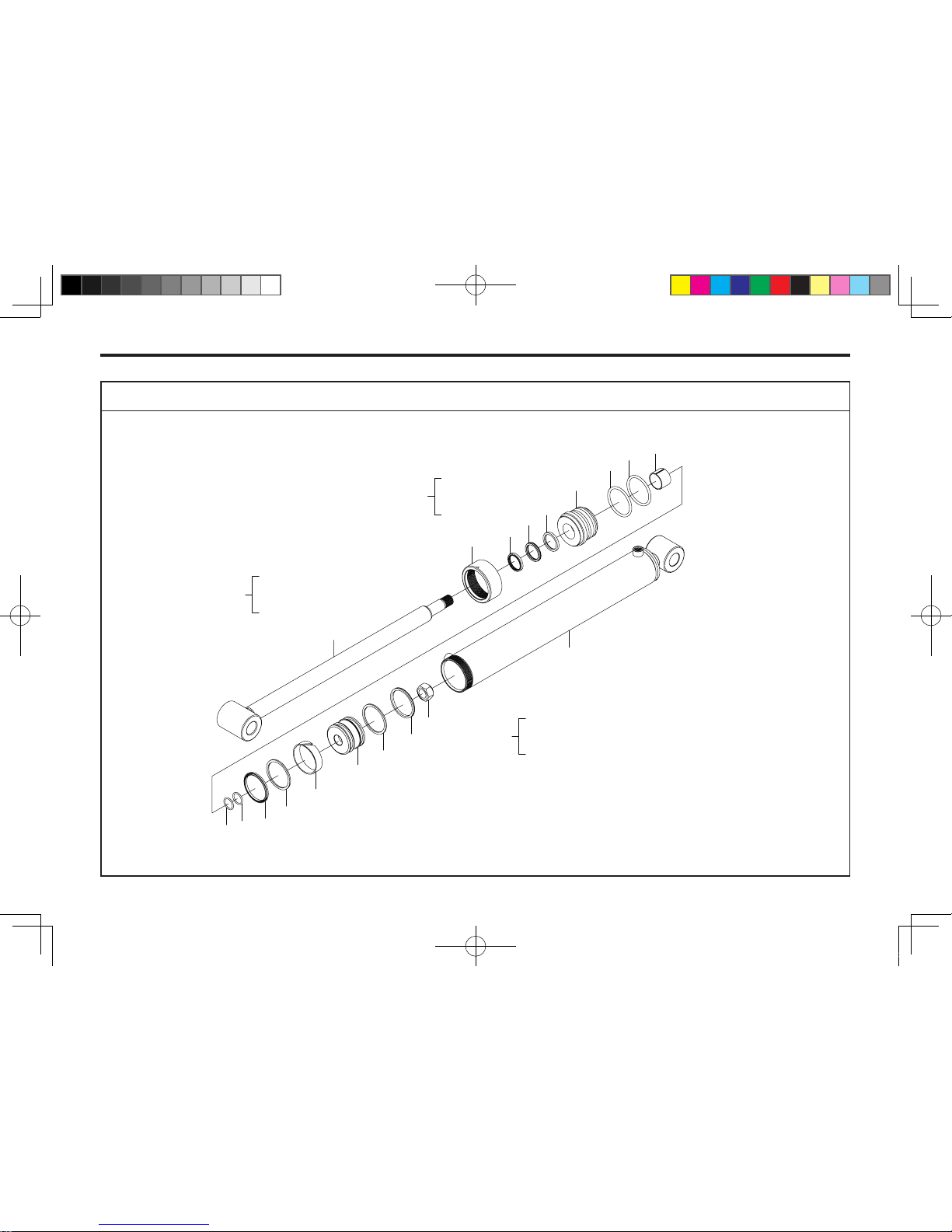
13-32 KL701
BOOM CYLINDER ASSEMBLY-LH
1
2
5
6
4
9
8
8
7
12
12
13
14
11
15
12
13
16
17
0
1
17
~
3
4
~
10
11
15
~
8
701OD02A
KL701-AU-13.indd 32 2013-05-10 오후 4:33:50
Page 89
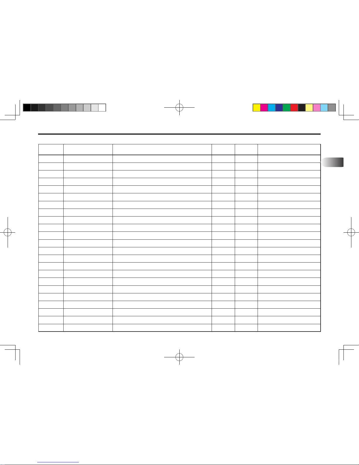
PART ILLUSTRATIONS 13-33
REF. NO PART. NO DESCRIPTION QTY I.C REMARK
13
0
1
2
3
4
5
6
7
8
9
10
11
12
13
14
15
16
17
22D003
22D003-R
OC70-8037
IA70-4055
IC70-4055
DSSD-R040
UPSK-Y040
UPIS-I040
OR1B-G065
DU04-0020
PA70-2746
PI70-2746
OR1B-G027
UPOS-I070
TRBR-0070
WEWR-0070
NTP0-U100-C
22D003-T
Boom Cylinder Ass'y LH, NO.1~17
Rod Ass'y
Cap, Outer, Ø70x80x37L
Seal Kit Head, NO.4~9
Cover, Inner, Ø70x40x55L
Dust, SDR 40x48x5/6.5
Packing, U, SKY 40x50x6
Packing, U, ISI 40x50x6
O-Ring, 1BG65
Bushing, DU, 40x44x20
Seal Kit Piston, NO.11~15
Piston, Ø70x27x46L
O-Ring, 1BG27
Packing, U, OSI 70x60x6
Backup, Ring, 70x60x3
Wearing, WR 70x65x15
Nut, 1-14UN
Tube Ass'y
1
1
1
1
1
1
1
1
2
1
1
1
2
2
2
1
1
1
KL701-AU-13.indd 33 2013-05-10 오후 4:33:50
Page 90
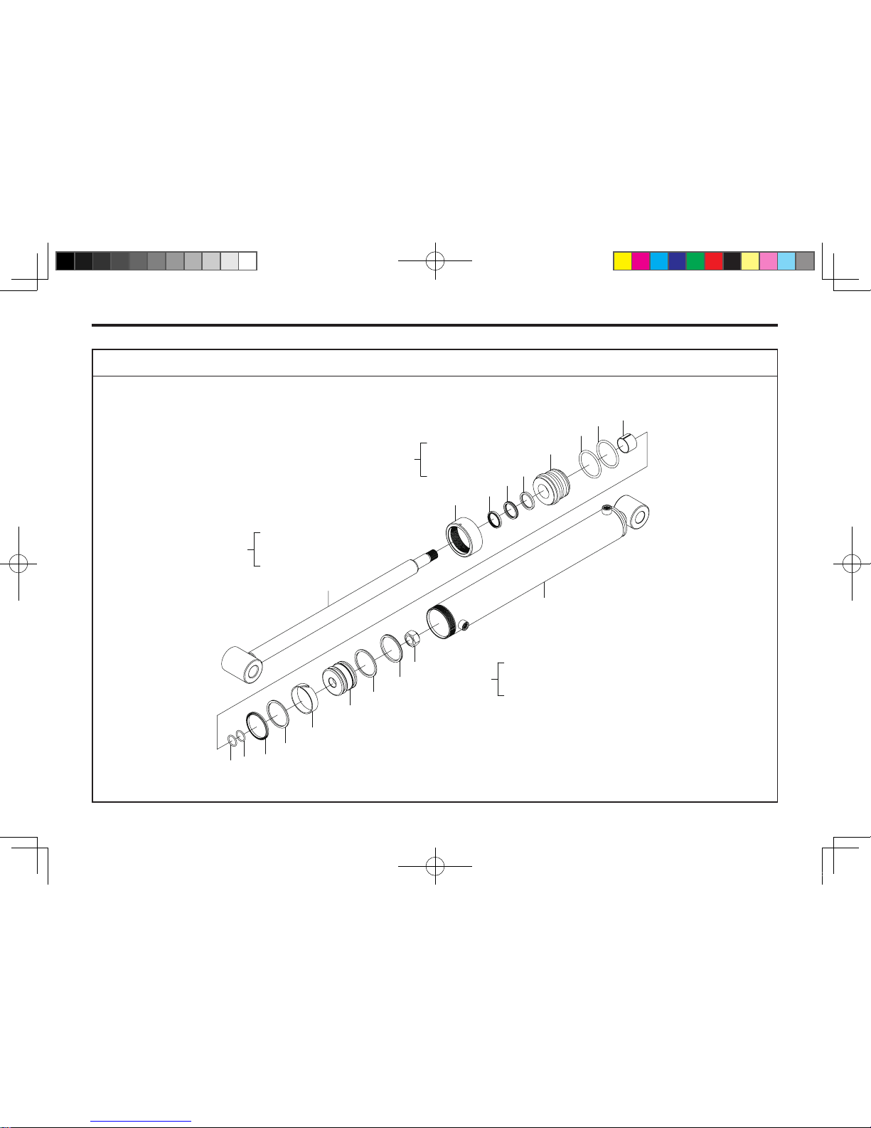
13-34 KL701
BOOM CYLINDER ASSEMBLY-RH
1
2
5
6
4
9
8
8
7
12
12
13
14
11
15
12
13
16
17
0
1
17
~
3
4
~
10
11
15
~
8
701OD03A
KL701-AU-13.indd 34 2013-05-10 오후 4:33:51
Page 91
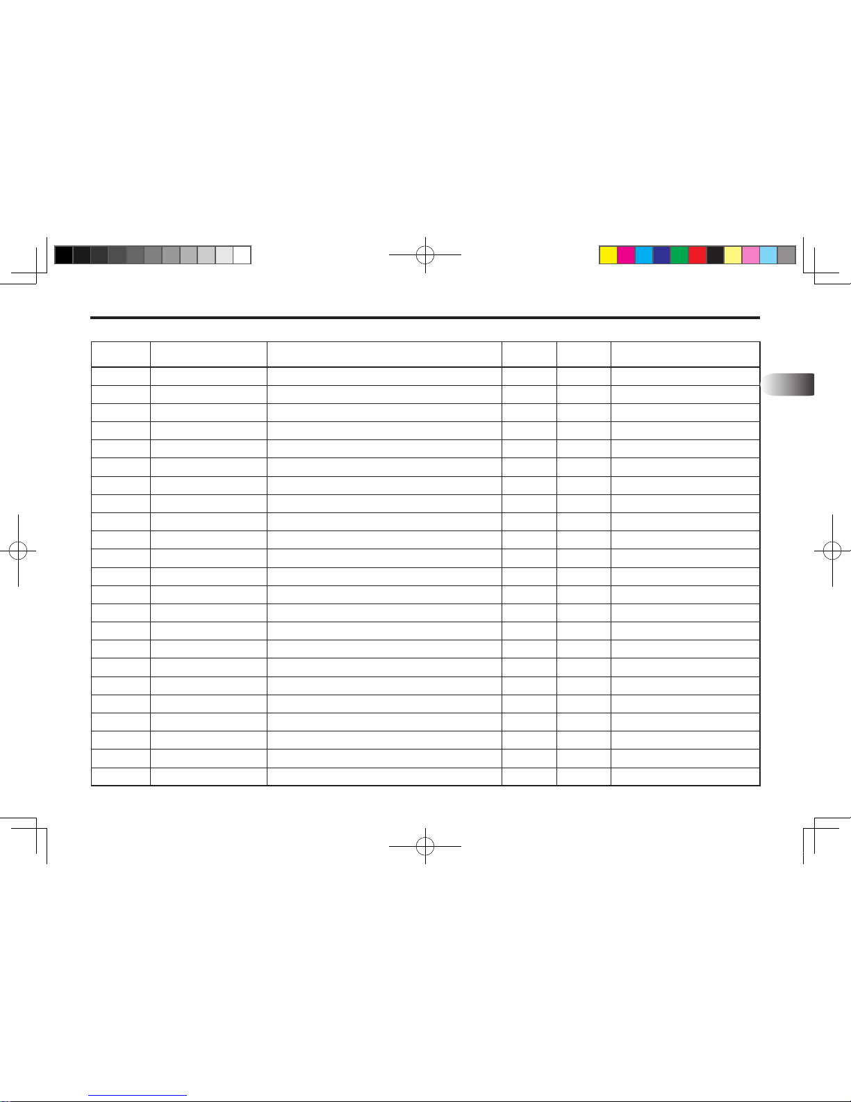
PART ILLUSTRATIONS 13-35
REF. NO PART. NO DESCRIPTION QTY I.C REMARK
13
0
1
2
3
4
5
6
7
8
9
10
11
12
13
14
15
16
17
22D004
22D004-R
OC70-8037
IA70-4055
IC70-4055
DSSD-R040
UPSK-Y040
UPIS-I040
OR1B-G065
DU04-0020
PA70-2746
PI70-2746
OR1B-G027
UPOS-I070
TRBR-0070
WEWR-0070
NTP0-U100-C
22D004-T
Boom Cylinder Ass'y RH, NO.0~15
Rod Ass'y
Cap, Outer, Ø70x80x37L
Seal Kit Head, NO.4~9
Cover, Inner, Ø70x40x55L
Dust, SDR 40x48x5/6.5
Packing, U, SKY 40x50x6
Packing, U, ISI 40x50x6
O-Ring, 1BG65
Bushing, DU, 40x44x20
Seal Kit Piston, NO.11~15
Piston, Ø70x27x46L
O-Ring, 1BG27
Packing, U, OSI 70x60x6
Backup, Ring, 70x60x3
Wearing, WR 70x65x15
Nut, 1-14UN
Tube Ass'y
1
1
1
1
1
1
1
1
2
1
1
1
2
2
2
1
1
1
KL701-AU-13.indd 35 2013-05-10 오후 4:33:51
Page 92
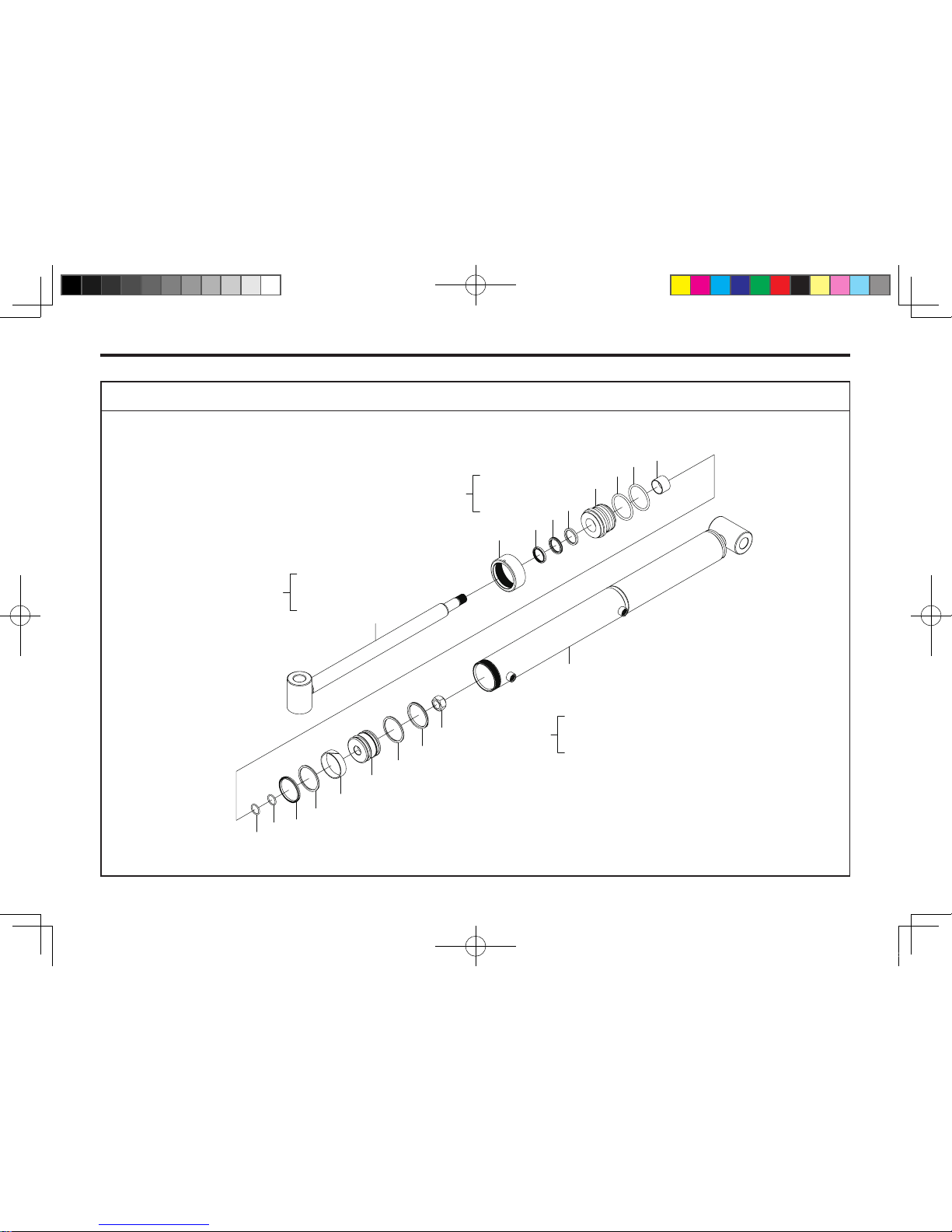
13-36 KL701
BUCKET CYLINDER ASSEMBLY
1
2
5
6
7
4
9
7
8
12
12
13
14
15
11
14
13
16
17
0
1
17
~
3
4
~
10
11
15
~
9
701OD04A
KL701-AU-13.indd 36 2013-05-10 오후 4:33:52
Page 93
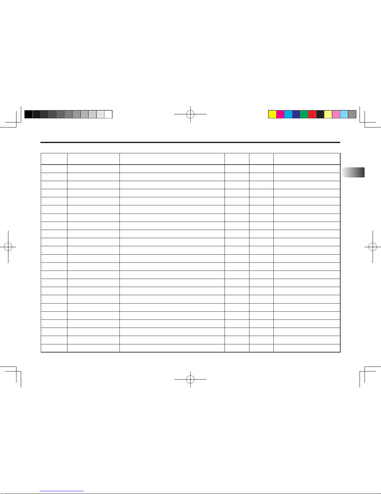
PART ILLUSTRATIONS 13-37
REF. NO PART. NO DESCRIPTION QTY I.C REMARK
13
0
1
2
3
4
5
6
7
8
9
10
11
12
13
14
15
16
17
22D001
22D001-R
OC70-8040
IA70-3565
IC70-3565
DSSD-R035
UPSK-Y035
UPIS-I035
OR1B-P060
DU03-5030
PA70-2746
PI70-2746
OR1B-G027
UPOS-I070
TRBR-0070
WEWR-0070
NTP0-U100-C
22D001-T
Boom Cylinder Ass'y, NO.1~17
Rod Ass'y
Cap, Outer, Ø70x80x40L
Seal Kit Head, NO.4~9
Cover, Inner, Ø70x35x65L
Dust, SDR 35x43x5/6.5
Packing, U, SKY 35x45x6
Packing, U, ISI 35x45x6
O-Ring, 1BP60
Bushing, DU, 35x39x30
Seal Kit Piston, NO.11~14
Piston, Ø70x27x46L
O-Ring, 1BG27
Packing, U, OSI 70x60x6
Backup, Ring, 70x60x3
Wearing, WR70x65x15
Nut, 1-14UN
Tube Ass'y
1
1
1
1
1
1
1
1
2
1
1
1
2
2
2
1
1
1
KL701-AU-13.indd 37 2013-05-10 오후 4:33:52
Page 94
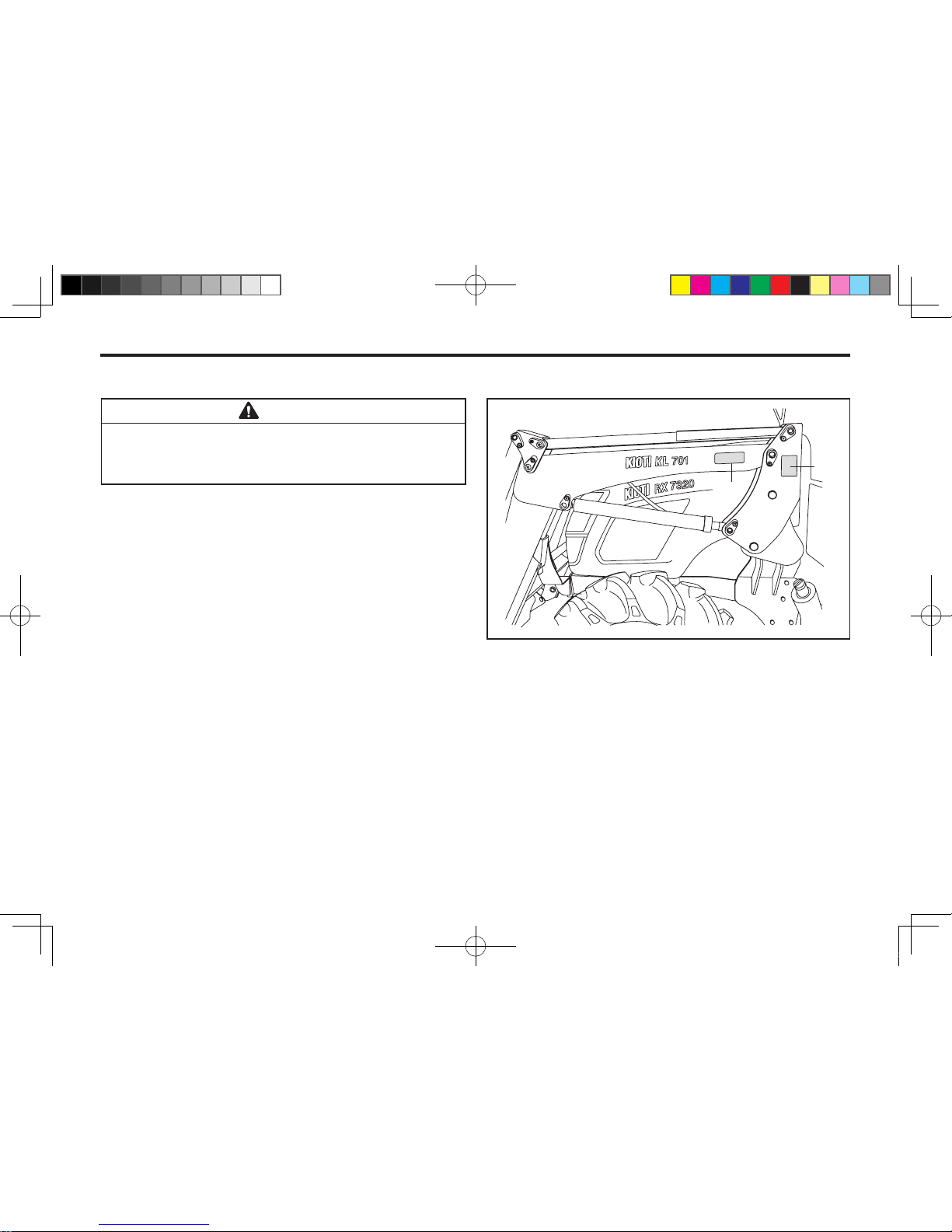
13-38 KL701
DECALS
Read and refer to the Tractor Operation Manual or
Decals on the Tractor. and Loader Decals on as
shown.
CAUTION
701OD05A
(1) 3104E-00001 (2) 3102E-00001
1
2
KL701-AU-13.indd 38 2013-05-10 오후 4:33:52
Page 95
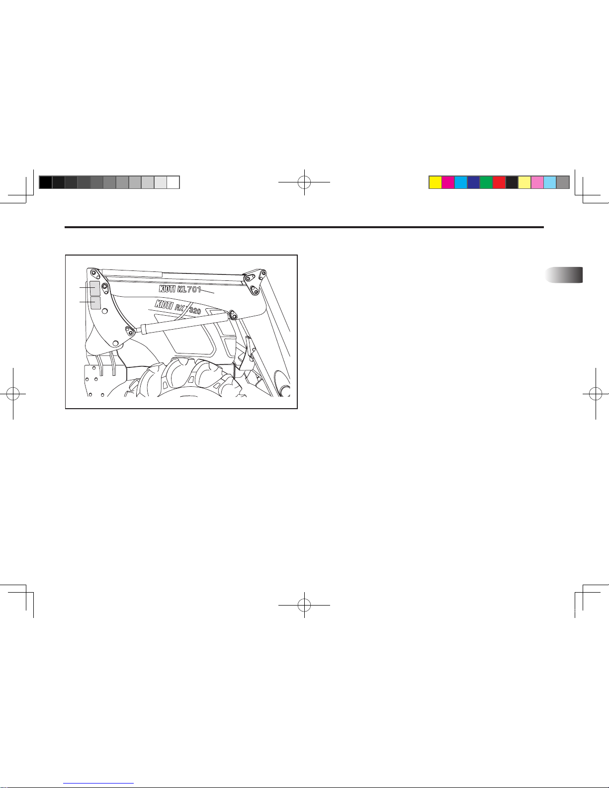
PART ILLUSTRATIONS 13-39
13
Refer to category “Safety decals”
701OD06A
(1) 3102E-00002 (2) 3102E-00003
(3) 3101E-00156
1
2
3
KL701-AU-13.indd 39 2013-05-10 오후 4:33:53
Page 96

MEMO
............................................................................................................................................................................
............................................................................................................................................................................
............................................................................................................................................................................
............................................................................................................................................................................
............................................................................................................................................................................
............................................................................................................................................................................
............................................................................................................................................................................
............................................................................................................................................................................
............................................................................................................................................................................
............................................................................................................................................................................
............................................................................................................................................................................
............................................................................................................................................................................
............................................................................................................................................................................
............................................................................................................................................................................
............................................................................................................................................................................
............................................................................................................................................................................
KL701-AU-13.indd 40 2013-05-10 오후 4:33:53
Page 97

14. LODER INSTALLATION
INSTALLATION INSTRUCTIONS ........................................................... 14-2
14
KL701-AU-14.indd 1 2013-03-29 오전 11:29:34
Page 98
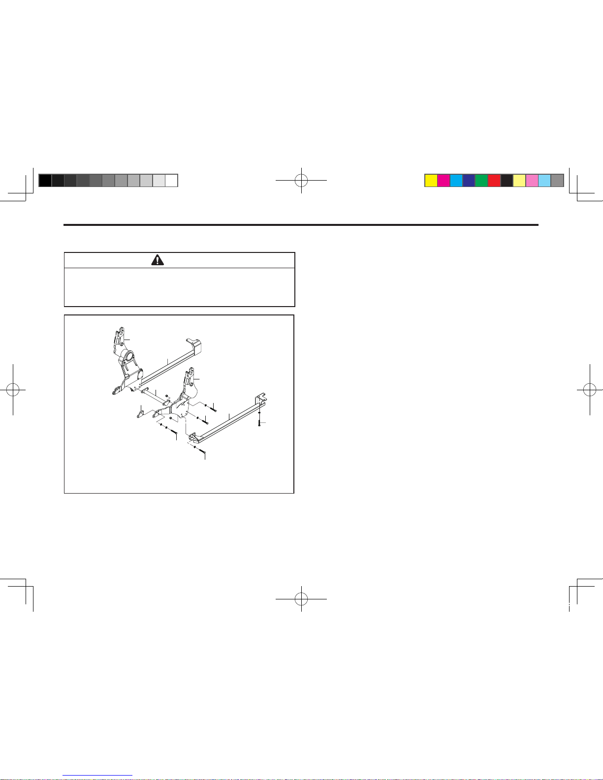
14-2 KL701
9
8
5
7
6
3
4
10
1
2
11
INSTALLATION INSTRUCTIONS
STEP 1.
Position tractor on hard level surface.
128OE01A
See your tractor Operator's manual for Safety pre-
cautions and Tractor preparations before installing the loader.
CAUTION
STEP 2 .
Release loader, bucket and mount kit box from pallet.
STEP 3.
Install Mounting Frame W.A, LH and
Mounting Frame W.A, RH.
1. Mounting Frame W.A, LH – 1EA
2. Mounting Frame W.A, RH – 1EA
3. Space, 16T– 2EA
4. Hex-Bolt, M14-P1.5 60L – 8EA
Spring-Washer, M14 – 8EA
Plain-Washer, M14 – 8EA
5. Hex-Bolt, M14-P1.5 60L – 8EA
Spring-Washer, M14 – 8EA
STEP 4.
Install Cross Bar.
6. Cross Bar – 1EA
7. Hex-Bolt, M16-P2.0 50L – 4EA
Spring-Washer, M16 – 4EA
Hex-Nut, M16-P2.0 – 4EA
KL701-AU-14.indd 2 2013-03-29 오전 11:29:35
Page 99
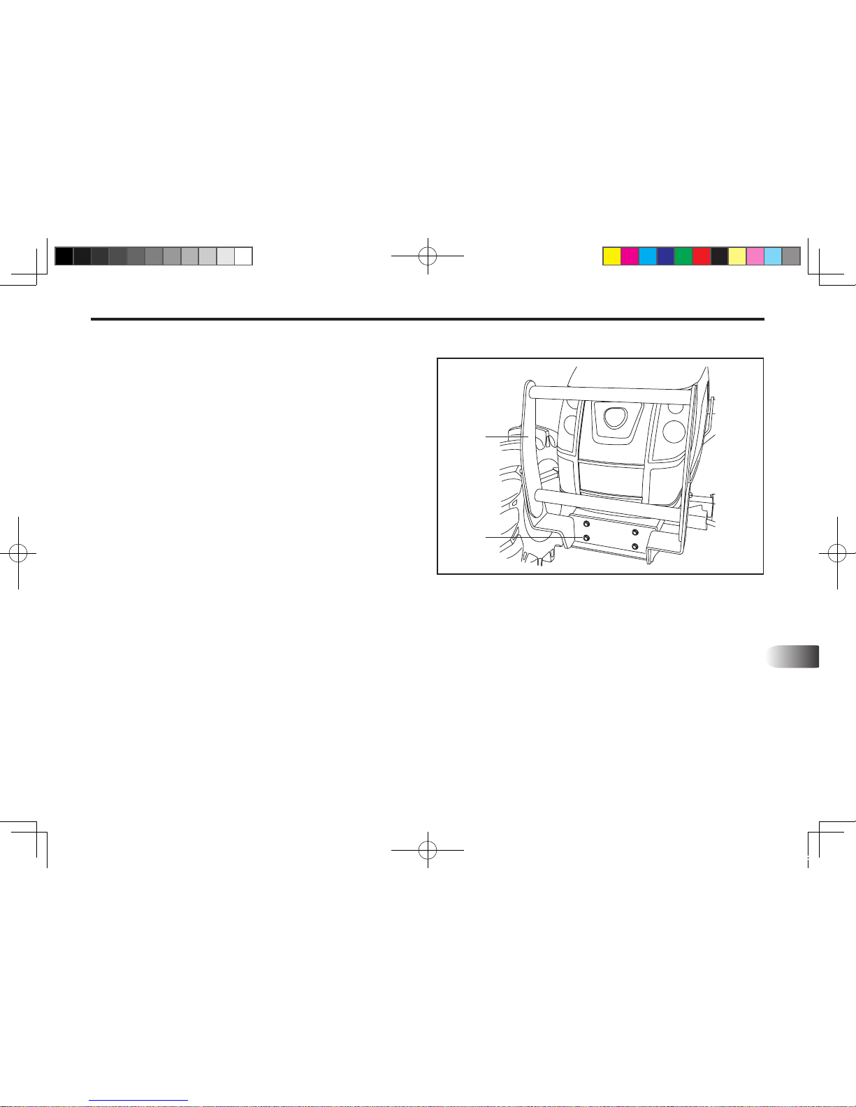
LOADER INSTALLATION 14-3
14
STEP 6.
Install Front Grill. (Optional)
1. Front Grill - 1EA
2. Hex-Bolt, M16-1.5P 40L – 4EA
Spring-Washer, M16 – 4EA
STEP 5.
Install Rear Frame W.A, LH/RH.
8. Rear Frame W. A, LH – 1EA
9. Rear Frame W. A, RH – 1EA
10. Hex-Bolt, M16-P2.0 50L – 4EA
Spring-Washer, M16 – 4EA
Hex-Nut, M16-P2.0 – 4EA
11. Hex-Bolt, M14-P1.5 50L – 6EA
Spring-Washer, M14 – 6EA
601OE02B
1
2
(1) Front Grill (2) Bolt
KL701-AU-14.indd 3 2013-03-29 오전 11:29:35
Page 100
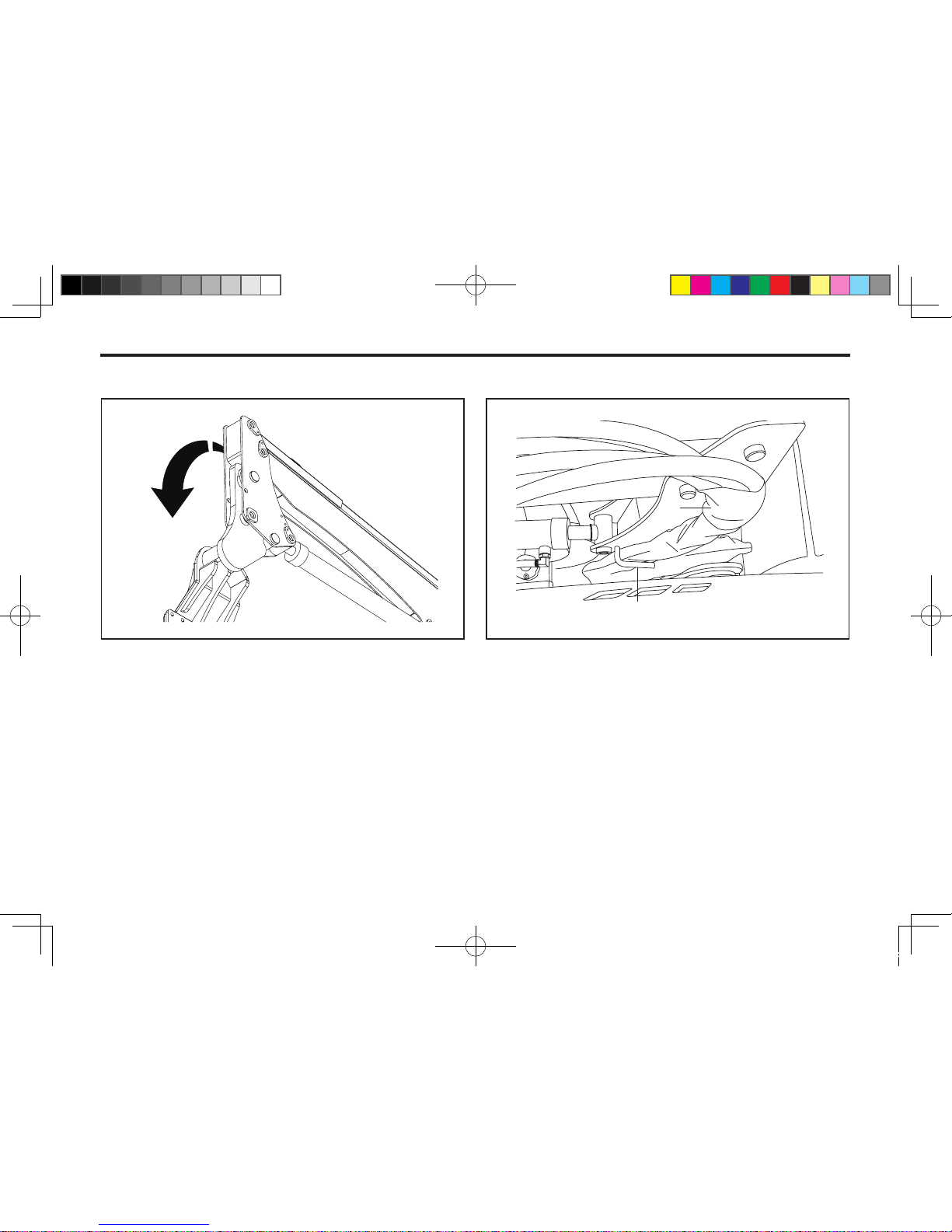
14-4 KL701
STEP 7.
Install Boom Ass’y
Hang the groove on the pin located on mounting frame.
STEP 8.
Hose "S"- shaped bend is xed after the hose guide.
701OE02A 601OE07A
1
2
(1) Hose (2) Hose Guide
KL701-AU-14.indd 4 2013-03-29 오전 11:29:36
 Loading...