


Congratulations, and welcome to the fabulous world of EX35/40/45/50 ownership, where serious work is made
fun again!
This versatile tractor is a culmination of the entire tractor and diesel knowledge gained by the Daedong Industrial Co.,LTD over the years since 1947 and has been designed with the finest materials and under rigid quality
control standards set forth by the KIOTI Engineering Department.
Knowledge of tractor operation is essential for many years of dependable service and reliability. To help new
owner's familiarize themselves with the KIOTI EX35/40/45/50, it is the policy of KIOTI tractor to provide an
owner's manual which includes helpful information about tractor safety, operation and maintenance. If the infor-
mation you seek is not found in this manual, your KIOTI tractor dealer will be happy to help you.
Please feel free to contact DAEDONG IND. CO.,LTD with your questions/concerns.
FOREWORD

This manual includes information titled as WARNING, CAUTION, IMPORTANT
and NOTE. These titles indicate the following:
SAFETY AND VEHICLE DAMAGE WARNING
NOTE
This indicates that interesting or helpful information is being
provided.
CAUTION
!!
!!
!
This indicates that a condition may result in damage to your
vehicle or its equipment if the caution is not heeded. Follow the
advice provided with the caution.
WARNING
This indicates that a condition may result in harm, serious injury
or death to you or other persons if the warning is not heeded.
Follow the advice provided with the warning.
!!
!!
!
This mark indicates emphasis on notable characteristics of working procedures, and information about technology for easier
operation.
IMPORTANT

ABBREVIATION LIST
ABBREVIA TIONS
4WD
API
ASAE
ASTM
fpm
Hi-Mid-Lo
HST
m/s
PTO
RH/LH
ROPS
m
-1
(rpm)
S
-1
(r/s)
SAE
SMV
DEFINITIONS
Four Wheel Drive
American Petroleum Institute
American Society of Agricultural Engineers, USA
American Society of Testing and Materials, USA
Feet Per Minute
High Speed-Middle Speed-Low Speed
Hydrostatic Transmission
Meters Per Second
Power Take Off
Right-hand and Left-hand sides are determined by facing in the direction of forward travel
Roll-Over Protective Structures
Revolutions Per Minute
Revolutions Per Second
Society of Automotive Engineers, USA
Slow Moving Vehicle

Various universal symbols have been used on the instruments and controls of your KIOTI tractor. Below is a list
of the universal symbols and their meanings.
UNIVERSAL SYMBOLS
Fuel-Level
Engine Coolant-Temperature
Parking Brake
Battery Charging Condition
Engine Oil-Pressure
Turn Signal
Power Take-Off Clutch Control-
ON Position
Power Take-Off Clutch Control-
OFF Position
Differential Lock
Position Control-Lowered Position
Hazard Warning Lights
Headlight-Low Beam
Headlight-High Beam
Four-Wheel Drive-ON
Fast
Slow
Creep
High Range
Middle Range
H
L
Low Range
Coolant
Preheat
QT lamp
H:High speed travel light
M:Middle speed travel light
L:Low speed travel light
Neutral Position
Single brake light
M
N

SAFETY PRECAUTIONS .............................................
SERVICING OF TRACTOR .........................................
SPECIFICATIONS.........................................................
DESCRIPTION OF OPERATING SYSTEM ..............
OPERATION...................................................................
THREE-POINT HITCH & DRAWBAR........................
HYDRAULIC UNIT ........................................................
TIRES, TREAD AND BALLAST .................................
MAINTENANCE .............................................................
PERIODIC SERVICE ....................................................
STORAGE.......................................................................
TROUBLESHOOTING ..................................................
OPTIONS ........................................................................
INDEX ..............................................................................
TABLE OF CONTENTS
SECTION
1
2
3
4
5
6
7
8
9
10
11
12
13
14

1
BEFORE OPERATING THE TRACTOR .................... 1-2
OPERATING THE TRACTOR .................................... 1-5
DRIVING THE TRACTOR ........................................... 1-8
PARKING THE TRACTOR ......................................... 1-9
OPERATING THE PTO ............................................. 1-10
USING 3-POINT HITCH ............................................. 1-10
SERVICING THE TRACTOR .................................... 1-11
TRACTOR SAFETY LABELS ................................... 1-14
SAFETY PRECAUTIONS

EX35/40/45/50
1
-2
A careful operator is the best operator.
Most accidents can be avoided by observing certain precautions. To help prevent accidents, use these safety
precautions, and pay attention to the
job at hand. If you can prevent an
accident, your time will have been well
spent.
BEFORE OPERA TING THE
TRACTOR
5. Keep safety decals clean of dirt and
debris.
6. Watch where you are going at all
times so that you are able to avoid
obstacles that can cause injury or
damage to your tractor.
7. When starting the tractor make sure
your path is clear of people to avoid
accidents caused by sudden
movements.
8. Before making reverse movements
with your tractor, you should always
check to see that the path is clear.
1. It is recommended that you read and
understand this entire manual before
operation of your new tractor. Failure to do so could result in accidents
or injury.
2. Only persons who are properly
trained should be allowed to operate
the tractor.
3. Read and follow all warning labels
and decals affixed to the tractor.
4. Replace any missing or damaged
decals as soon as it is practical. A
list of decals is shown on page114~16.
T46O101A T46O102A

1
-3
SAFETY PRECAUTIONS
16. All persons using the tractor should
have knowledge of its proper operation and should read this manual
carefully.
17. Never get off the tractor without setting the parking brake, lowering the
implement to the ground and shutting of the tractor.
18. No alterations should be made to
your KIOTI tractor.
12. Never start the engine while standing on the ground.
13. Only the operator should ride on the
tractor unless a passenger seat is
installed. Keep bystanders away
from the tractor while in operation.
14. When getting on and off the tractor,
handholds and step plates should
always be used. This will help to
prevent accidental slips trips and
falls.
15. Be sure to scrape off mud or soil
from your shoes before mounting
the tractor.
T46O103A T46O104A T46O105A
9. Never operate this tractor or any
other agricultural equipment while
under the influence of alcohol,
drugs or while fatigued.
10. While working in cooperation with
other tractors always communicate
your intentions.
11. Do not start your tractor by shorting across the starter.

EX35/40/45/50
1
-4
21. Extra caution should be taken when
driving tractors with narrow tread
widths. For added stability you
should adjust your rear wheel tread
width, see page 8-4.
19. Before starting your tractor you
should depress the clutch and
make sure that all shift levers are
in the neutral position and parking
brake is applied.
20. For your safety ROPS with a seat
belt is recommended for all
applications.
(1) Tread
T46O106A
T46O107A
A ROPS should never be modified by
welding, grinding or cutting, as this
can weaken the ROPS structure. If any
components of the ROPS unit is
damaged, it must be replaced.
If the ROPS unit is removed or loos-
ened for any reason, the parts should
be fitted back to their original positions
and all bolts should be properly
torqued.
Always use seat belt when the
tractor is equipped with a ROPS.
Never use the seat belt when trac-
tor is not equipped with a ROPS.
NOTE

1
-5
SAFETY PRECAUTIONS
1. Avoid accidental contact with gear
shift levers while the engine is
running. Unexpected tractor movements can result in bodily injury.
2. Do not park your tractor on a steep
incline, and remember to shut off the
engine and PTO before dismounting the tractor.
OPERATING THE TRACTOR
T46O109A
T46O108A T46O110A
3. Do not operate your tractor in an enclosed building without the proper
ventilation. Exhaust fumes contain
carbon monoxide and may cause
series injury or death.

EX35/40/45/50
1
-6
7. Always use the proper ballast weight
on your tractor when using rear
implements.
8. Watch front and rear to avoid obstacles at row ends, near trees and
around other obstructions.
4. Make sure that all pressure lines are
tight before starting the tractor.
5. Pull only from the drawbar. Never
hitch anything to the axle housing or
any other point except the drawbar.
Pulling from any other location only
increase the risk of serious personal
injury or death.
6. If the front of the tractor tends to rise
up when heavy implements are attached to the three point hitch,
weights should be installed on the
tractor. Do not operate the tractor
with a light front end.
(1) Drawbar
T46O111A T46O112A T46O113A

1
-7
SAFETY PRECAUTIONS
9. Do not leave equipment in the
raised position when the vehicle is
stopped or unattended.
10. When using implements or attachments with your tractor you should
first read their respective owner's
manual. You should always keep
their safe operation procedures in
mind.
11. You should be familiar with your
equipment and its limitations.
12. If abused or used incorrectly your
tractor can become dangerous to
you and bystanders. Overloading
your tractor or using unsafe equipment can also be dangerous and
should be avoided. Refer to the
"Specifications of Implement
Limitation", which outlines the
maximum load for safe tractor
operation.
15. When working in groups, always let
the others know what you are going to do before you do it.
16. Never "freewheel". Disengaging the
clutch or shifting into neutral while
descending a slope as this could
lead to a loss of control.
17. Do not operate near ditches, holes,
embankments, or other terrain features which may collapse under the
tractor's weight. The risk of tractor
upset is even higher when the
ground is loose or wet.
13. Driving forward out of a ditch or
steep inclines can cause the tractor to tip over backwards. To avoid
this you should back out of these
positions. Four wheel drive tractors
can give you a false sense of security in the tractors ability to maneuver out of these positions, so
extra caution should be taken.
14. Never try to get on or off a moving
tractor.
T46O114A T46O115A

EX35/40/45/50
1
-8
1. Lock the brake pedals together when
traveling at road speeds. Brake both
wheels simultaneously when making an emergency stop. Uneven
braking at road speeds could cause
the tractor to tip over.
DRIVING THE TRACTOR
(1) Interlock (2) Brake Pedal (L)
(3) Brake Pedal (R)
(1) Interlock (2) Brake Pedal (L)
(3) Brake Pedal (R)
MANUAL type
T46O118AT46O117AT46O116A
HST type
2. Always slow the tractor before
turning. Turning at high speed may
tip the tractor over or cause an operator to lose control of the tractor.

1
-9
SAFETY PRECAUTIONS
3. Make sure that the Slow Moving Vehicle (SMV) sign is clean and visible.
Use hazard lights as required.
1. Disengage the PTO, lower all
implements, place all control levers
in the neutral position, set the parking brake, stop the engine and remove the key.
PARKING THE TRACTOR
(1) SMV Emblem
T46O119A T46O120A
4. Observe all local traffic and safety
regulations.
5. Turn the headlights on. Dim them
when meeting another vehicle.
6. Drive at speeds that allow you to
maintain control at all times.
7. Do not apply the differential lock
while traveling at road speeds. As
the tractor may lose the ability to
steer.
8. Avoid sudden movements of the
steering wheel as this can cause a
loss of control of the tractor. This
risk is especially great when traveling at road speeds.
9. Do not operate an implement while
the tractor is on the road. Lock the
three point hitch in the raised
position.
10. When towing other equipment, use
a safety chain and place an SMV
emblem on it as well.

EX35/40/45/50
1
-10
(1) 3-point hitch lowering speed knob
(A) “FAST” (C) “LOCK”
(B) “SLOW”
USING 3-POINT HITCH
1. Use the 3-point hitch only with equipment designed for 3-point hitch
usage.
2. When using a 3-point hitch mounted
implement, be sure to install the
proper counterbalance weight on the
front of the tractor.
3. When transporting on the road, set
the implement lowering control in the
"LOCK" position to hold the implement in the raised position.
(1) PTO Shield
(2) PTO Shaft Cap
OPERATING THE PTO
T46O122AT46O121A T46O123A
1. Make sure the tractor is completely
stopped, gears are in neutral and all
moving components have completely stopped before connecting,
disconnecting, adjusting, cleaning or
servicing any PTO driven equipment.
2. Keep the PTO shield in place at all
times. Replace the PTO shaft cap
when the shaft is not in use.
3. Before installing or using PTO driven
equipment, read the manufacturer's
manual and review the safety labels
attached to the equipment.
4. When operating stationary PTO driven
equipment, always apply the tractor
parking brake and place chocks behind and in front of the rear wheels.
Stay clear of all rotating parts.
5. Do not attach a PTO driven implement
if the implement’s safety shields are
damaged or not in place. Rotating
shafts are an entanglement hazard.

1
-11
SAFETY PRECAUTIONS
2. Allow the tractor time to cool off before servicing any part that may have
become hot while the tractor was
running.
3. You must always stop the engine before refueling the tractor. Avoid overfilling the tractor or spilling the fuel.
4. Before jump starting a dead battery,
read and follow all of the instructions.
5. It is recommended to keep a first aid
kit and fire extinguisher handy at all
times.
In order to service your tractor you must
park it on a flat level surface, set the
parking brake, place the gear shift lever in neutral and stop the engine.
1. Do not smoke while working around
the battery or when refueling your
tractor. Keep all sparks and flames
away from the battery and fuel tank.
The battery presents an explosive
hazard because it gives off hydrogen and oxygen… especially when
recharging.
SERVICING THE TRACTOR
6. Do not remove the radiator cap while
the coolant is hot. When cool, slowly
rotate the cap to the first stop and
allow sufficient time for excess pressure to escape. After all the pressure is released remove the cap
completely. If your tractor is
equipped with a coolant recovery
tank, add coolant there rather than
to the radiator.
T46O124A T46O125A T46O126A

EX35/40/45/50
1
-12
(1) Cardboard (3) Magnifying Glass
(2) Hydraulic Line
12. Make sure that wheel bolts have
been tightened to the specified
torque.
13. Escaping hydraulic fluid under pres-
sure has sufficient force to penetrate skin, causing serious personal injury. Be sure to release all
residual pressure. Before disconnecting hydraulic lines.
Before adding pressure to the hydraulic system, make sure that all
connections are tight and that all
line, pipes and hoses are free of
damage.
7. When working with your tractors
electrical components you must first
disconnect the battery cables.
8. To ensure that there are no accidents
from sparks you must first disconnect the negative battery cable.
T46O129AT46O128AT46O127A
9. Tire mounting should be done by
qualified professionals, with the
proper equipment.
10. Maintaining correct tire pressure is
important for the life of your tires.
Do not inflate the tires above the
recommended pressure specified
in the owner’s manual or on the
tractor tire.
11. Securely support the tractor when
changing wheels or the wheel tread
width.

1
-13
SAFETY PRECAUTIONS
14. Fluid escaping from pinholes may
be invisible. Do not use hands to
search for suspected leaks;
Use a piece of cardboard or wood,
instead. Use of safety goggles or
other eye protection is also highly
recommended. If injured by escaping fluid, see a medical doctor at
once. This fluid can produce gangrene and/or severe allergic
reaction.
T46O130A T46O131A
15. Keep environmental pollution in
mind. When replacing coolant or
oil, dispose of it the right way.
Be sure to observe all relevant
regulations when you dispose of
engine oil, transmission oil, fuel,
coolant, filters and battery.

EX35/40/45/50
1
-14
T46O132A
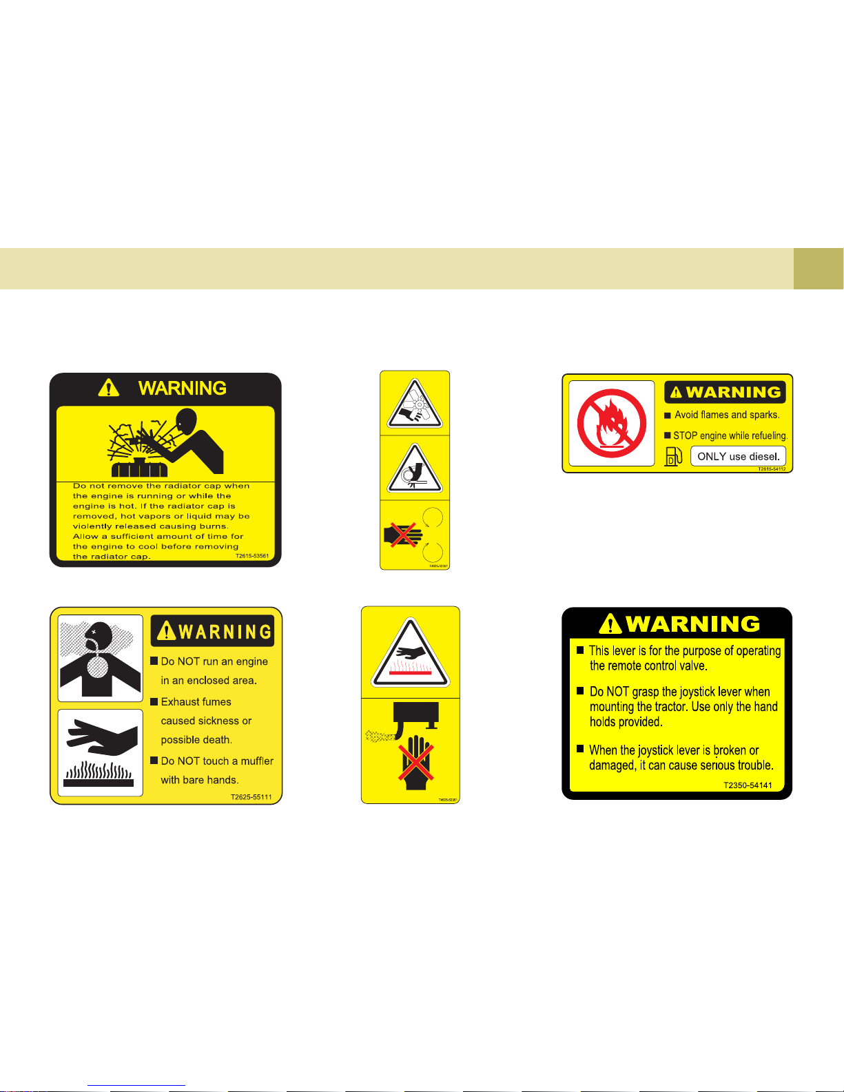
TRACTOR SAFETY LABELS
1
-15
SAFETY PRECAUTIONS
(2) Part No. : T2625-55111 (4) Part No. : T4625-52361
(3) Part No. : T4625-52351 (5) Part No. : T2615-54112
(6) Part No. : T2350-54141
(1) Part No. : T2615-53561

EX35/40/45/50
1
-16
(7) Part No. : T2325-50512 (9) Part No. : T2181-54121
(10) Part No. : T2325-50743(8) Part No. : T2445-50724

2
SERVICING ..................................................................2-2
SERVICING OF TRACTOR

2
-2 EX35/40/45/50
SERVICING
T46O201A
Your dealer is interested in your new
tractor and has the desire to help you
get the most value from it. After reading this manual thoroughly, you will find
that you can do some of the regular
maintenance yourself.
However, when in need of parts, warranty or major service, be sure to see
your KIOTI dealer. For service, contact the KIOTI dealership from which
you purchased your tractor or your lo-
cal authorized KIOTI dealer.
When in need of parts, be prepared to
give your dealer both the tractor and
engine serial numbers.
The tractor serial number is located on
the front axle support on the left side
of the tractor. The engine serial number is located on the upper side of the
engine head cover. The transmission
number is located on the rearward of
the tractor and the transmission case
in the upward of the PTO cover. Locate the serial numbers now and record
them in the space provided.
S/N Identification No.
Engine Serial No.
T ransmission Serial No.
To be filled in by purchaser
Date of Purchase
(1) S/N Identification Plate (2) Transmission Serial Number (3 ) Engine Serial Number
Before using NON-KIOTI approved
implements or attachments, contact
your nearest dealer regarding safety
and application.

3
SPECIFICATIONS........................................................ 3-2
TRAVELING SPEED .................................................... 3-4
IMPLEMENT LIMITATIONS ........................................ 3-7
SPECIFICATIONS

3
-2 EX35/40/45/50
SPECIFICATIONS
Model
Engine
Capacities
Model
Type
Displacement cc (cu.in.)
Gross Engine Power HP (kW)
PTO HP (kW)
Rated speed rpm
Fuel Tank
(U.S. gals.)
T/M Case
(U.S. gals.)
F/A Case
(U.S. gals.)
Clutch
Transmission
Speed
KPH (MPH)
4-Wheel drive
Steering
Brake
Traveling
4 Cyl., In-line Vertical, Water-cooled 4-cycle
diesel engine
1,999 (121.98)
41 (30.5)
2,600
45 (11.9)
7.5 (2.0)
Dry type single stage
Button Switch FWD
Hydrostatic Power steering
Wet disk
3 Cyl., In-line Vertical, Water-cooled 4-cycle
diesel engine
1,826 (111.43)
38 (28.3)
2,600
45 (11.9)
7.5 (2.0)
Dry type single stage
Button Switch FWD
Hydrostatic Power steering
Wet disk
3B183LXM
28.5 (21.2)
52 (13.7)
F12/R12
[Option:F24/R24]
Synchro Shuttle
1.4~23.4 (0.8~14.5)
[Option:0.16~23.4
(0.1~14.5)]
4A200LXM
34.0 (25.3)
52 (13.7)
F12/R12
[Option:F24/R24]
Synchro Shuttle
1.4~24.5 (0.9~15.2)
[Option:0.17~24.5
(0.11~15.2)]
3B183LXH
27.0 (20.1)
42 (11.1)
3 Range HST Hydraulic
servo mechanism
Twin pedal
0~25.8 (0~16.0)
4A200LXH
32.5 (24.2)
42 (11.1)
3 Range HST Hydraulic
servo mechanism
Twin pedal
0~27.0 (0~16.7)
[MODEL: EX35/40/45/50]
EX40
Manual HST
EX35
Manual HST

3
-3
SPECIFICATIONS
Model
Engine
Capacities
Model
Type
Displacement cc (cu.in.)
Gross Engine Power HP (kW)
PTO HP (kW)
Rated speed rpm
Fuel Tank
(U.S. gals.)
T/M Case
(U.S. gals.)
F/A Case
(U.S. gals.)
Clutch
Transmission
Speed
KPH (MPH)
4-Wheel drive
Steering
Brake
Traveling
4 Cyl., In-line Vertical, Water-cooled 4-cycle
diesel engine
2,197 (134.06)
45 (33.5)
2,600
45 (11.9)
7.5 (2.0)
Dry type single stage
Button Switch FWD
Hydrostatic Power steering
Wet disk
4A220LXM
38.0 (28.3)
52 (13.7)
F12/R12
[Option:F24/R24]
Synchro Shuttle
1.5~25.8 (0.9~16.0)
[Option: 0.18~25.8
(0.1~16.0)]
4A220LXH
36.0 (26.8)
42 (11.1)
3 Range HST Hydraulic
servo mechanism
Twin pedal
0~28.5 (0~17.7)
4 Cyl., In-line Vertical, Water-
cooled 4-cycle diesel engine
2,435 (148.6)
50 (37.2)
2,600
45 (11.9)
7.5 (2.0)
Dry type single stage
Button Switch FWD
Hydrostatic Power steering
Wet disk
4B243LXM
39.5 (29.5)
52 (13.7)
F12/R12
[Option:F24/R24]
Synchro Shuttle
1.5~25.8 (0.9~16.0)
[Option: 0.18~25.8
(0.1~16.0)]
4B243LXH
37.5 (27.9)
42 (11.1)
3 Range HST Hydraulic
servo mechanism
Twin pedal
0~28.5 (0~17.7)
[MODEL: EX35/40/45/50]
EX50
Manual HST
EX45
Manual HST

3
-4 EX35/40/45/50
Model
Hydraulic
PTODimensions
1,667 (3,375)
1,664 (3,338)
8-16 / 6PR
27-8.5-15 / 4PR
10-16.5 / 6PR
13.6-24 / 6PR
41-14.0-20 / 4PR
14.9-24 / 6PR
Position,draft and mixed control
63.9 (16.8)
SAE Category I
1,131 (2,493)
1,334 (2,940)
Hydrostatic,Independent
SAE 1-3/8, 6 Splines
540
16/32 Involute spline
2,000
3,505 (138.0)
1,635 (64.4)
2,415 (95.1)
1,880 (74.0)
1,245 (49.0)
1,290~1,490 (50.8~58.7)
340 (13.4)
2.91 (9.5)
1,780 (3,924)
1,745 (3,847)
7-16 / 6PR
27-8.5-15 / 4PR
27-10.5-15 / 6PR
12.4-24 / 6PR
41-14.0-20 / 4PR
43-16-20 / 4PR
Position,draft and mixed control
57.8 (15.2)
SAE Category I
1,081 (2,383)
1,172 (2,583)
Hydrostatic, Independent
SAE 1-3/8, 6 Splines
540
16/32 Involute spline
2,000
3,422 (134.7)
1,552 (61.1)
2,395 (94.3)
1,767 (69.6)
1,248 (49.1)
1,221~1,348 (48.1~53.1)
320 (12.6)
2.85 (9.3)
Weight(With ROPS)
kg (lbs.)
Front
Rear
Hydraulic control
Pump capacity
/min (U.S.gpm)
Three point hitch
Lift capacity
Rear
Mid
(Option)
Overall length
(includes 3P)
mm(in.)
Overall width
(minimum tread)
mm(in.)
Overall height(from Top of ROPS)
mm(in.)
Wheel base mm(in.)
Wheel tread
Min.ground clearance
mm(in.)
Min. turning radius
(with brake)
m(feet)
24” aft. of hitch
Lift Link Ends
Type
Shaft size
Speed rpm
Front
mm(in.)
Rear mm(in.)
AG
Turf
Industrial
AG
Turf
Industrial
Standard Tire size
kg (lbs.)
[MODEL: EX35/40/45/50]
EX40
Manual
HST
EX35
Manual
HST

3
-5
SPECIFICATIONS
Model
Hydraulic
PTODimensions
1,800 (3,968)
1,785 (3,935)
Weight(With ROPS)
kg (lbs.)
Front
Rear
Hydraulic control
Pump capacity
/min (U.S.gpm)
Three point hitch
Lift capacity
Rear
Mid
(Option)
Overall length
(includes 3P)
mm(in.)
Overall width
(minimum tread)
mm(in.)
Overall height(from Top of ROPS)
mm(in.)
Wheel base mm(in.)
Wheel tread
Min.ground clearance
mm(in.)
Min. turning radius
(with brake)
m(feet)
24” aft. of hitch
Lift Link Ends
Type
Shaft size
Speed rpm
Front
mm(in.)
Rear mm(in.)
AG
Turf
Industrial
AG
Turf
Industrial
Standard Tire size
kg (lbs.)
[MODEL: EX35/40/45/50]
9.5-16 / 6PR
29-12.5-15 / 4PR
12-16.5 / 6PR
13.6-26 / 6PR
21.5L-16.1 / 4PR
17.5L-24 / 8PR
Position,draft and mixed control
63.9 (16.8)
SAE Category I
1,131 (2,493)
1,334 (2,940)
Hydrostatic, Independent
SAE 1-3/8, 6 Splines
540
16/32 Involute spline
2,000
3,505 (138.0)
1,646 (64.8)
2,445 (96.3)
1,880 (74.0)
1,365 (53.7)
1,305~1,480 (51.4~58.3)
370 (14.6)
3.13 (10.2)
EX45
Manual
HST
9.5-16 / 6PR
29-12.5-15 / 4PR
12-16.5 / 6PR
13.6-26 / 6PR
21.5L-16.1 / 4PR
17.5L-24 / 8PR
Position,draft and mixed control
63.9 (16.8)
SAE Category I
1,131 (2,493)
1,334 (2,940)
Hydrostatic, Independent
SAE 1-3/8, 6 Splines
540
16/32 Involute spline
2,000
3,505 (138.0)
1,646 (64.8)
2,445 (96.3)
1,880 (74.0)
1,365 (53.7)
1,305~1,480 (51.4~58.3)
370 (14.6)
3.13 (10.2)
1,792 (3,950)
1,780 (3,924)
EX50
Manual
HST

3
-6 EX35/40/45/50
TRAVELING SPEED
Km/h(m/h)
Hi-Low Main
Forward
Low
Mid
High
1
2
3
4
1
2
3
4
1
2
3
4
EX35 EX40 EX45/50 EX35 EX40 EX45/50
Shuttle Reverse
1.36(0.85)
1.90(1.18)
2.44(1.52)
3.32(2.06)
3.48(2.16)
4.86(3.02)
6.24(3.88)
8.48(5.27)
9.61(5.97)
13.43(8.35)
17.25(10.72)
23.42(14.55)
1.42(0.88)
1.99(1.24)
2.56(1.59)
3.47(2.16)
3.64(2.26)
5.08(3.16)
6.53(4.06)
8.86(5.51)
10.05(6.25)
14.04(8.72)
18.04(11.21)
24.48(15.21)
1.50(0.93)
2.10(1.31)
2.69(1.67)
3.65(2.27)
3.83(2.38)
5.36(3.33)
6.88(4.28)
9.34(5.80)
10.59(6.58)
14.80(9.20)
19.00(11.81)
25.80(16.03)
1.21(0.75)
1.69(1.05)
2.17(1.35)
2.95(1.83)
3.09(1.92)
4.32(2.68)
5.55(3.45)
7.53(4.68)
8.54(5.31)
11.93(7.41)
15.33(9.53)
20.81(12.94)
1.27(0.79)
1.77(1.10)
2.27(1.41)
3.08(1.91)
3.23(2.01)
4.52(2.81)
5.80(3.60)
7.88(4.90)
8.93(5.55)
12.48(7.76)
16.03(9.96)
21.76(12.94)
1.33(0.83)
1.86(1.16)
2.39(1.49)
3.25(2.02)
3.41(2.12)
4.76(2.96)
6.11(3.80)
8.3(5.16)
9.41(5.85)
13.15(8.17)
16.89(10.50)
22.92(14.24)
[MANUAL TRANSMISSION TYPE 12X12]
Forward
EX35 EX40 EX45/50
EX35 EX40 EX45/50
RANGE
Reverse
Km/h(m/h)
Low
Mid
High
6.08(3.78)
10.49(6.52)
25.85(16.06)
6.36(3.95)
10.97(6.82)
27.03(16.80)
6.70(4.16)
11.56(7.18)
28.47(17.69)
[HST TYPE]
6.08(3.78)
10.49(6.52)
25.85(16.06)
6.36(3.95)
10.97(6.82)
27.03(16.80)
6.70(4.16)
11.56(7.18)
28.47(17.69)

3
-7
SPECIFICATIONS
[MANUAL TRANSMISSION TYPE 24X24 : OPTIONAL]
Km/h(m/h)
Hi-Low Main
Forward
Low
Mid
Low
1
2
3
4
1
2
3
4
1
2
3
4
EX35 EX40 EX45/50 EX35 EX40 EX45/50
Shuttle Reverse
0.16(0.10)
0.23(0.14)
0.29(0.18)
0.39(0.24)
0.41(0.26)
0.57(0.35)
0.73(0.45)
1.00(0.62)
1.13(0.70)
1.58(0.98)
2.03(1.26)
2.75(1.71)
0.17(0.11)
0.23(0.14)
0.30(0.19)
0.41(0.26)
0.43(0.27)
0.60(0.37)
0.77(0.48)
1.04(0.65)
1.18(0.73)
1.65(1.03)
2.12(1.32)
2.88(1.79)
1.18(0.11)
0.25(0.16)
0.32(0.20)
0.43(0.27)
0.45(0.28)
0.63(0.39)
0.81(0.50)
1.1(0.68)
1.24(0.77)
1.74(1.08)
2.23(1.39)
3.03(1.88)
0.14(0.09)
0.20(0.12)
0.26(0.16)
0.35(0.22)
0.36(0.22)
0.51(0.32)
0.65(0.40)
0.89(0.55)
1.00(0.62)
1.40(0.87)
1.80(1.12)
2.45(1.52)
0.15(0.09)
0.21(0.13)
0.27(0.17)
0.36(0.22)
0.38(0.24)
0.53(0.33)
0.68(0.42)
0.93(0.58)
1.05(0.65)
1.47(0.91)
1.88(1.17)
2.56(1.59)
0.16(0.10)
0.22(0.14)
0.28(0.17)
0.38(0.24)
0.40(0.25)
0.56(0.35)
0.72(0.45)
0.98(0.61)
1.11(0.69)
1.55(0.96)
1.99(1.24)
2.69(1.67)
Creep
High

3
-8 EX35/40/45/50
Km/h(m/h)
Hi-Low Main
Forward
Low
Mid
High
1
2
3
4
1
2
3
4
1
2
3
4
EX35 EX40 EX45/50 EX35 EX40 EX45/50
Shuttle Reverse
1.36(0.85)
1.90(1.18)
2.44(1.52)
3.32(2.06)
3.48(2.16)
4.86(3.02)
6.24(3.88)
8.48(5.27)
9.61(5.97)
13.43(8.35)
17.25(10.72)
23.42(14.55)
1.42(0.88)
1.99(1.24)
2.56(1.59)
3.47(2.16)
3.64(2.26)
5.08(3.16)
6.53(4.06)
8.86(5.51)
10.05(6.25)
14.04(8.72)
18.04(11.21)
24.48(15.21)
1.50(0.93)
2.10(1.31)
2.69(1.67)
3.65(2.27)
3.83(2.38)
5.36(3.33)
6.88(4.28)
9.34(5.80)
10.59(6.58)
14.80(9.20)
19.00(11.81)
25.80(16.03)
1.21(0.75)
1.69(1.05)
2.17(1.35)
2.95(1.83)
3.09(1.92)
4.32(2.68)
5.55(3.45)
7.53(4.68)
8.54(5.31)
11.93(7.41)
15.33(9.53)
20.81(12.94)
1.27(0.79)
1.77(1.10)
2.27(1.41)
3.08(1.91)
3.23(2.01)
4.52(2.81)
5.80(3.60)
7.88(4.90)
8.93(5.55)
12.48(7.76)
16.03(9.96)
21.76(12.94)
1.33(0.83)
1.86(1.16)
2.39(1.49)
3.25(2.02)
3.41(2.12)
4.76(2.96)
6.11(3.80)
8.3(5.16)
9.41(5.85)
13.15(8.17)
16.89(10.50)
22.92(14.24)
Creep
High

3
-9
SPECIFICATIONS
IMPLEMENT LIMIT ATIONS
This KIOTI tractor has been thoroughly tested for proper performance with implements approved by KIOTI. Use with
implements which are approved by KIOTI and which exceed the maximum specifications listed below, or which are otherwise unfit for use with this KIOTI tractor may result in malfunctions or failures of the tractor, damage to other property and
injury to the operator or others. [Any malfunctions or failures of the tractor resulting from use with improper implements are
not covered by the warranty.]
NOTE : Implement size may vary depending on soil types and field conditions.
Front
Tread (max. width)
Rear
Lifting Capacity max. loading weight .......... The max. allowable load which can be put on the 24 in. aft of hitch : W
0
Implement weight ....................................... The implement's weight which can be put on the lower link : W
1
Max. drawbar load ...................................... W
2
Trailer loading weight .................................. The max. loading weight for trailer (without trailer's weight) : W
3
Model
Item
Implement weight W1 and / or size
Actual figures
Max. Drawbar Load W
2
Model
Item
650 kg
(1433.0 lbs.)
1,248 mm (49.1 in)
1,245 mm (49.0 in)
1,365 mm (53.7 in)
1,348 mm (53.1 in)
1,490 mm (58.7 in)
1,515 mm (59.6 in)
As in the following list
(Shown in the next page)
Lifting Capacity max.
loading weight
(24 in. aft of hitch)
T46O301A
Trailer loading weight
W
3
Max. capacity
3,500 Kg
(7716.1 lbs.)
EX35
EX40
EX45/50
EX35
EX40
EX45/50
1,081 Kg (2,383 lbs. )
1,131 Kg (2,493 lbs.)

3
-10 EX35/40/45/50
REMARKS
EX35 EX40
IMPLEMENT
Loader
Backhoe with sub frame
Tiller
Box Blade
Rear Blade
Rotary Cutter
Grooming Mower
Aerator
Landscape Rakes
REMARKS
Max. Bucket width mm(in)
Max. Digging depthmm(ft.in)
Max. working widthmm(in)
Max. Cutting width mm(in)
Max. Cutting width mm(in)
Max. Cutting width mm(in)
Max. Cutting width mm(in)
Max. Width mm(in)
Max. Cutting width mm(in)
EX45/50
1,676 (66)
2,280 (7.48)
1,650 (65)
2,133 (84)
2,133 (84)
1,650 (65)
1,828 (72)
1,828 (72)
2,133 (84)
1,828 (72)
2,590 (8.5)
1,854 (73)
2,133 (84)
2,133 (84)
1,854 (73)
1,828 (72)
1,828 (72)
2,483 (96)
1,828 (72)
2,590 (8.5)
1,854 (73)
2,133 (84)
2,133 (84)
1,854 (73)
1,828 (72)
1,828 (72)
2,483 (96)

4
EXTERIOR VIEW ......................................................... 4-2
INSTRUMENT PANEL AND SWITCH ........................4-4
FOOT AND HAND CONTROLS ................................. 4-5
DESCRIPTION OF OPERATING SYSTEM

4
-2 EX35/40/45/50
EXTERIOR VIEW
(1) Seat
(2) Steering Wheel
(3) Fuel Cap Cover
(4) Hood/Bonnet
(5) Head Light
(6) ROPS
(7) Fender
(8) Turn Signal Lamp
T46O401A

4
-3DESCRIPTION OF OPERATING SYSTEM
(1) Turn Signal Lamp
(2) Top Link
(3) Transmission Oil Gauge/Dipstick
(4) PTO Shield
(5) Crank Lifting Rod
(6) Telescopic Sway bar
(7) Draw Bar
(8) Lower Link
T46O402A

4
-4 EX35/40/45/50
(1) Left Turn Indicator
(2) Tachometer
(3) Right Turn Indicator
(4) Fuel Gauge
(5) Coolant Temp. Gauge
(6) Turn Signal Switch
(7) Head Light Switch
(8) Key Switch
(9) Front Wheel Drive Switch
(10) Hazard Lamp Switch
(11) Cruise Control (HST only)
(12) PTO Select Switch (Auto <-> Manual)
(13) PTO Switch
INSTRUMENT PANEL AND SWITCHES
T46O406A

4
-5DESCRIPTION OF OPERATING SYSTEM
FOOT AND HAND CONTROLS
(1) Shuttle Shift Lever
(2) Hand Throttle Lever
(3) Clutch Pedal
(4) Tilt Steering Pedal
(5) Parking Brake Lock Lever
(6) Brake Pedal (L)
(7) Brake Pedal (R)
(8) Main Gear Shift Lever
(9) Creep Gear Shift Lever
(10) Range Gear Shift Lever
(11) 3-Point Hitch Lowering Speed Knob
(12) Mid PTO Shift Lever
(13) Differential Lock Pedal
(14) Joystick Lever
(15) Double Acting Lever(A,B)
(16) Foot Throttle
(17) Double Acting Lever(C,D)
(18) Draft Control Lever
(19) Lift Position Control Lever
Manual Type
T46O407A

4
-6 EX35/40/45/50
(1) Hand Throttle Lever
(2) Brake Pedal (L)
(3) Brake Pedal (R)
(4) Tilt Steering Pedal
(5) Parking Brake Lock Lever
(6) HST Forward Pedal
(7) HST Reverse Pedal
(8) Range Gear Shift Lever
(9) Differential Lock Pedal
(10) 3-Point Hitch Lowering Speed Knob
(11) Mid PTO Shift Lever
(12) Joystick Lever
(13) Double Acting Lever(A,B)
(14) Double Acting Lever(C,D)
(15) Draft Control Lever
(16) Lift Position Control Lever
T46O408A
HST T ype

5
PRE-OPERATION........................................................5-2
OPERATING NEW TRACTOR ...................................5-3
OPERATING THE ENGINE ........................................ 5-4
OPERATING THE TRACTOR .................................. 5-11
OPERATION

5
-2 EX35/40/45/50
- Walk around inspection.
- Check the engine oil level
- Check the transmission oil level
- Check the coolant level
- Clean the grill and radiator screen.
- Check the air cleaner and evacuator valve.
- Check the brake pedals and linkages
- Check all dash gauges and indicators
- Check head lights, tail lights, and all
working lights.
- Check accessible wiring harness for
any damage.
- Check the seat belt and ROPS for
damage.
- Refuel (See "daily check" in the periodic service section)
- Check all danger and warning labels.
PRE-OPERATION
It is a good practice to know the condition of your tractor before you start
it. You should perform a routine check
before each use.
CHECK ITEM
T o avoid personal injury:
Be sure to check and service the
tractor on a level surface with
the engine shut off and the parking brake “ENGAGED”.
Follow the refueling procedures
providing “DAIL Y CHECK” in periodic service section.
Familiarize yourself with all
danger, warning and caution
labels. Maintain all labels in
their proper places in good legible condition.
DAILY CHECK
!!
!!
!
CAUTION

5
-3
OPERATION
OPERATING NEW TRACTOR
CHANGING LUBRICATING OIL
FOR NEW TRACTORS
How a new tractor is handled and maintained determines the life of the tractor.
A new tractor just off the factory production line has of course been, tested,
but the various parts are not accustomed to each other, therefore care
should be taken to operate the tractor
for the first 50 hours at a slower speed
and avoid excessive work or operation
until the various parts become "brokenin." The manner in which the tractor is
handled during the "breaking-in" period
greatly affects the life of your tractor.
Therefore, to obtain the maximum performance and the longest life of the
tractor, it is very important to properly
break-in your tractor.
In handling a new tractor, the following
precautions should be observed.
You should not operate your tractor
at full speed for the first fifty hours
of use.
Avoid sudden starts and stops.
In cold climates, allow your tractor
plenty of time to warm up.
Do not run the engine at speeds
faster than necessary.
Use due caution when operating your
tractor on rough roads or terrain.
The above precautions are not limited
to new tractors only, but are a good
practice for tractors regardless of their
age.
Special attention should be given to
new tractors lubrication oil. New parts
are not accustomed to each other and
are not broken in properly. Small metal
grit can develop in the lubricating system as metal parts begin to "break in"
and continuous use of the contaminated
oil can cause damage and failure.
Therefore you should change the
tractor's oil after the break-in period.
For further details of the oil change and
service schedule, see "maintenance"
section.

5
-4 EX35/40/45/50
T46O552A
(1) To set the parking brake:
1) Interlock the brake pedals
2) Depress the brake pedals
3) Latch the brake pedals with the
parking brake lever.(Check that
the parking brake lamp on the
instrument cluster illuminates.)
(2) To release the parking brake press
the brake pedals again.
STARTING THE ENGINE
(1) Parking Brake Lever
(2) Brake Pedals
(3) Interlock the Brake Pedals
(A) "Depress"
(B) "Push Down"
1. MAKE SURE THE PARKING
BRAKE IS SET
Using starting fluid or ether to start
your tractor will cause damage
and void your tractors warranty.
T o avoid damage to the starter and
battery you should never continuously start your tractor for more
than 10 seconds at a time.
IMPORTANT
Make sure that the parking
brake pedals are fully depressed before pulling the parking brake lever up.
IMPORTANT
OPERATING THE ENGINE
T o avoid personal injury:
You must read and understand
the warning and caution labels
on your tractor.
Proper ventilation is required
when operating your tractor inside a building or enclosed area.
Remember that exhaust fumes
can be deadly.
Never start your tractor’s engine
while standing on the ground.
This can prevent an unexpected
accident from happening.
!!
!!
!
CAUTION
NOTE
When the parking brake is engaged,
the parking brake lamp on the instrument cluster illuminates. When
releasing it, the parking brake lamp
is turned off.
HST T ype
MANUAL T ype

5
-5
OPERATION
T46O554AT46O553A
T46O502A
2. MAKE SURE THE FUEL COCK IS
IN THE OPEN POSITION.
(1) Fuel Cock
(A) Close (B) Open
(C) Air Bleeding
(1) Forward/Reverse Lever
(2) PTO Switch
(3) Range Gear Shift Lever (Hi-Mid-Lo)
3. PLACE THE PTO CLUTCH LEVER
IN "OFF" POSITION.
4. PLACE THE SPEED CONTROL
PEDAL IN "NEUTRAL" POSITION
(HST TYPE).
5. SHIFT THE FORWARD/REVERSE
LEVER TO NEUTRAL POSITION
(MANUAL TYPE).
NOTE
The speed control pedal automati-
cally return to neutral when the
operator's foot is released from the
pedal.
6. PLACE THE RANGE GEAR
SHIFT LEVER (HI-MID-LO) IN
"NEUTRAL" POSITION.
(2) PTO Switch
(3) Range Gear Shift Lever (Hi-Mid-Lo)(HST)
(4) Speed Control Pedal
MANUAL T ype
HST T ype

5
-6 EX35/40/45/50
T46O505A
8. SHIFT THE THROTTLE LEVER TO
“DECRESE” POSITION.
9. INSERT THE KEY INTO THE KEY
SWITCH AND TURN IT “ON”.
MAINTAIN IT UNTIL THE PREHEAT LAMP IS TURNED “OFF”
(APPROX. 8 SEC.).
7. MOVE THE POSITION CONTROL
LEVER.
To lower implement, move the position
control lever forward.
(1) Position Control Lever
(A) "DOWN"
(1) Hand Throttle Lever
"INCREASE"
"DECREASE"
(1) Key Switch
(
) Off ( ) Manual Pre-Heat
(
) Acc ( ) Start
(
) On(Auto Pre-Heat)
T46O556A T46O557A

5
-7
OPERATION
10. TURN THE KEY TO “ST ART” POSITION AND RELEASE WHEN
THE ENGINE ST ARTS.
1. Be careful not to run the starting
motor longer than 10 seconds due
to its heavy current consumption.
2. If the tractor has not started in 10
seconds stop operating the starter,
wait 30 seconds and then repeat the
starting procedure.
3. Prior to restarting, be sure that the
flywheel is completely stopped.
4. For manual preheating, turn and hold
the key from ON to preheat position.
Only when the brake pedal is en-
gaged with the range shift lever in
neutral position, the motor can be
started(HST).
Only with the shuttle lever in neu-
tral position, the motor can
be started(Manual).
NOTE
11. CHECK TO SEE THAT ALL THE
WARNING LAMPS ON THE INSTRUMENT CLUSTER TURN
“OFF”.
(1) Electrical Charge
(2) Parking Brake
(3) Glow Plug Indicator
(4) Engine Oil Pressure
T46O558A

5
-8 EX35/40/45/50
T46O510A
STOPPING THE ENGINE
1. You must first slow the engine to the
idle position before turning the engine off.
2. Remove the key.
WARMING UP
During warm up of the engine,
be sure that the parking brake
is set.
During warm up of the engine,
make sure that all shift levers
are in the neutral position.
[CHECK EASY CHECKER LAMPS]
1. When the key is turned "ON", lamps
(1), (4) should come on. If trouble
should occur at any location while
the engine is running, the warning
lamp corresponding to that location
comes on.
2. Glow plug indicator (3) also comes
on when the key is turned "ON" to
preheat the engine and goes off automatically when preheat is
completed.
3. The parking brake warning lamp (2)
comes on while parking brake is applied and goes off when it is released.
If any lamp remains on, immediately
stop the engine and determine the
cause.
Daily checks with the Easy
Check only, are not sufficient.
Never fail to conduct daily
checks carefully by referring to
Daily Check. (See “DAILY
CHECK” in Section 10)
IMPORTANT
!!
!!
!
CAUTION
!!
!!
!
CAUTION
If the engine does not stop, con-
sult with your local DAEDONG
dealer.
After starting your tractor's engine allow a five minute warm up period before applying any load to the tractor.
If a load is applied to the tractor before it has time to warm up, serious
damage, can occur like premature
wear, breakage, or seizure.

5
-9
OPERATION
Hydraulic oil serves as transmission
fluid to protect and lubricate moving
parts. This fluid is also circulated
through out the hydraulic circuit to
operate functions like steering, three
point hitch, and remote functions. In
cold weather, the oil will be cold with
increased viscosity. This can cause
delayed oil circulation or abnormally
low hydraulic pressure for some time
after engine start-up. This in turn can
result in trouble to the hydraulic
system. To prevent the above, observe the following instructions:
Warm up the engine at a high idle
according to the table below:
WARM-UP AND TRANSMISSION OIL
IN THE LOW TEMPERA TURE RANGE
Do not operate the tractor un-
der full load condition until it is
sufficiently warmed up.
IMPORTANT
Ambient
temperature
Above 0 ° C
(32 ° F)
0 ~ -10 ° C
(32 ~ 14 ° F)
-10 ~ -20 ° C
(14 ~ -4 ° F)
Below -20 ° C
(-4 ° F)
Warm-up time
requirement
At least 5 minutes
5 ~ 10 minutes
10 ~ 20 minutes
More than 20 minutes

5
-10 EX35/40/45/50
T46O511A
JUMP STARTING
(1) Dead Battery (2) Jumper Cables
(3) Helper Battery
the other vehicle to touch. Start the
vehicle's engine after connecting the
cables and let it run for a few
moments. Turn off all accessories on
both vehicles. Then start the disabled tractor.
7. Disconnect the battery cables in the
exact opposite order as they were
attached.
When jump starting the engine, follow
the instructions below to safely start
the engine.
1. Use a battery of the same voltage
as the disabled tractor battery to
jump start the tractor. Locate the
good battery in a safe place where
the jumper cables will reach.
2. Engage the parking brake of the tractor and shift the transmission gear
to the neutral position.
3. Put on safety goggles and rubber
gloves.
4. Attach the red clamp to the positive
terminal of the dead battery, and attach the other end to the positive terminal of the helper battery.
5. Clamp the black cable to the Engine
hooks or other ground source and attach the other end to the negative
cable of the helper battery.
6. If the helper battery is in another
vehicle, do not allow the tractor and
Keep fire, spark, cigarette, etc.,
from the battery.
If the tractor battery is frozen,
jump starting the engine is
prohibited.
Do not connect the (-) jumper
cable to the negative(-) terminal
of the discharged battery.
!!
!!
!
CAUTION
Use a ground away from the
battery

5
-11
OPERATION
T46O513AT46O512A
TO FOLD THE ROPS
(1) Grip Bolt (2) Set Pin
(3) Clip Pin
(1) ROPS
1. Remove the clip pin and set pin. 2. Loosen the grip bolt and fold the
ROPS.
OPERATING THE TRACTOR
You should always stop the
engine, remove the key and set
the parking brake before raising
or folding the ROPS.
Always perform such tasks from
a safe and stable position at the
rear of the tractor.
Folding the ROPS should only be
done when absolutely necessary,
and should be returned to the upright position as soon as possible.
!!
!!
!
CAUTION
T o avoid personal injury:
Hold the ROPS tightly with both
hands and fold the ROPS slowly
and carefully.
!!
!!
!
CAUTION
T46O514A
3. Align pin holes, insert set pin, and
secure them with the clip pin.
T o avoid personal injury:
Make sure the pins are properly
installed and secured.
(1) Grip Bolt (2) Set Pin
(3) Clip Pin
!!
!!
!
CAUTION

5
-12 EX35/40/45/50
T46O517A
1. ADJUSTING THE OPERATOR’S
POSITION
(1) Position Height Adjuster (4) Weight Adjuster
(2) Height Adjuster Leve (A) “PULL IN”
(3) Seat Reclining Lever
(1) OPERATOR'S SEAT
STARTING
To avoid personal injury:
Make sure that the seat is com-
pletely secured after each
adjustment.
Do not allow any person other
than the driver to ride on the
tractor.
!!
!!
!
CAUTION
T46O515A T46O516A
TO RAISE THE ROPS TO
UPRIGHT POSITION
1. Remove both the grip bolt, clip pin
and set pin.
2. Raise ROPS to the upright position.
3. Align pin holes, insert set pin and
secure them with the clip pin.
4. Fix the ROPS with the grip bolt.
To avoid personal injury:
Make sure that pins are properly
installed and secured.
(1) Grip Bolt (2) Set Pin
(3) Clip Pin
!!
!!
!
CAUTION
T o avoid personal injury:
The ROPS must be raised slowly
and carefully.
!!
!!
!
CAUTION

5
-13
OPERATION
(1) HAZARD LIGHT SWITCH
When hazard light switch is pushed
“on”, the hazard lights flash along
with the indicator on the instrument
panel. Push the switch to “off” to
turn flashers off.
2. SELECTING LIGHT SWITCH POSITIONS
(1) Hazard / Turn Signal Indicator
(2) Turn Signal Light Switch
(3) Hazard Light Switch
T46O559AT46O518A
(2) TRAVEL/HEIGHT ADJUSTMENT
Pull out the position adjust lever and
slide the seat backward or forward, as
required.
(1) Seat Belt
Adjust the seat belt for proper fit and
connect to the buckle. The seat belt is
an auto-locking retractable type.
(3) SEAT BELT
After adjusting the operator’s
seat, be sure to check that the
seat is properly locked.
IMPORTANT
T o avoid personal injury:
Always use your seat belt when
the ROPS is installed.
Do not use the seat belt if your
tractor is not equipped with a
ROPS or when it is removed.
!!
!!
!
CAUTION
(2) TURN SIGNAL LIGHT SWITCH
To indicate a right turn, push forward.
To indicate a left turn, push rearward.

5
-14 EX35/40/45/50
HST T ype
MANUAL T ype
(1) Head Light Switch
(A) “OFF” (B) “ON (LOW)”
(C) “ON (HIGH)”
(3) HEAD LIGHT SWITCH
(A): Head lights OFF.
(B): Head lights - Low Beam ON.
(C): Head lights - High Beam ON.
T46O522A
(1) Brake Pedal (L) ( 2) Brake Pedal (R)
(3) Interlock
(A)Lock (B)Release
(1) Brake Pedal (L) ( 2) Brake Pedal (R)
(3) Interlock
(A) Release (B) Lock
3. CHECKING THE BRAKE PEDAL
1. Before operating the tractor on the
road or before applying the parking
brake, be sure to interlock the right
and left pedals as illustrated.
2. Use individual brakes to assist in
making sharp turns at slow speeds
(Field Operation Only).
Disengage the brake pedal interlock
and depress only one brake pedal.
3. Be sure brake pedals have equal ad-
justment when using locked together.
(1) BRAKE PEDAL (RIGHT AND LEFT)
WARNING
!!
!!
!
To avoid personal injury:
Applying one rear wheel brake at
a time can cause the tractor to
swerve or roll over at high speeds.
T46O561AT46O560A
NOTE
Be sure to return switch to center
position after turning.
When the left or right turn signal is
activated, the indicated turning light will
flash and the other will be off.

5
-15
OPERATION
T o help prevent premature clutch
wear.
The clutch pedal must be en-
gaged slowly and disengaged
quickly.
Do not rest your foot on the
clutch pedal.
Select the proper gear and en-
gine speeds according to the
type of job you are doing.
IMPORTANT
4. RAISE THE IMPLEMENT.
The clutch is disengaged when the
clutch pedal is fully pressed down
(Manual type).
5. DEPRESS THE CLUTCH PEDAL
(MANUAL TYPE)
(1) Position Control Lever
(A) UP
(1) Clutch Pedal
T46O523A T46O524A
T o avoid personal injury:
Do not release the clutch suddenly,
it may cause the tractor to lunge
forward unexpectedly.
HST models do not have a
clutch pedal.
!!
!!
!
CAUTION

5
-16 EX35/40/45/50
T46O562A
(1) Forward/Reverse Shift Lever
(2) Main Gear Shift Lever
(3) Creep Gear Shift Lever
(4) Range Gear Shift Lever(Hi-Mid-Lo
)
MANUAL T ype
(1) FORWARD/REVERSE SHIFT LEVER
Push forward or pull backward to select forward or reverse. The direction
of travel can be changed without changing the main shift.
(2)MAIN GEAR SHIFT LEVER
4 level shifts are possible with one
lever. Synchro-mesh type. Just release
the clutch during driving to change the
speed.
The synchronized shuttle shift
lever may be shifted while the
tractor is moving slowly and the
clutch is depressed.
Sudden gear shift changes with-
out clutching may cause transmission damage.
IMPORTANT
6. SELECTING THE TRA VEL SPEED
(MANUAL Type)
N -"NEUTRAL POSITION"
- "HIGH"
-"MIDDLE"
-"LOW"
F -"FORWARD"
R - "REVERSE”
Shifting the shuttle & high
speeds without slowing down
may cause premature synchronizer wear

5
-17
OPERATION
(4)CREEP GEAR SHIFT LEVER
HOW TO USE CREEP GEAR SHIFT
LEVER(OPTION-MANUAL Type)
If you misuse or mishandle the creeping speed, it may cause damage to
the unit, so please note the following.
(3)RANGE GEAR SHIFT LEVER (HI-MID-
LO)
The range gear shift can only be shifted
when tractor is completely stopped and
clutch is depressed. If it is difficult to
shift the range gear, take the following
actions.
1. Be sure the range gear shift lever is
in neutral position.
2. Release clutch pedal(Manual type)
or slightly depress the speed control pedal to rotate the gears inside
of transmission. Release the speed
control pedal to neutral(HST only).
3. Depress clutch pedal(Manual type)
and then shift the range gear shift
lever.
To avoid transmission damage,
depress clutch pedal and stop
tractor before shifting between
ranges.
IMPORTANT
1. Possible times to use:
• A deep tilling application
• When unable to maintain a constant
speed in harsh field conditions
• Transplanting
• When loading and unloading
It may be easy to stall the engine
when operating the tractor in
high range at low engine rpm’s.
!!
!!
!
CAUTION

5
-18 EX35/40/45/50
(1) Range Gear Shift Lever (Hi-Mid-Lo)
H “HIGH SPEED”
N “NEUTRAL POSITION”
M “MIDDLE SPEED”
L “LOW SPEED”
HST T ype
With a creeper transmission, an operator has the option to use 24 F and 24R
gears.
To stop the tractor, be sure to
disengage the clutch first, then
depress the brake pedal. This is
because creep range gives high
torque at low forward speeds
thus making braking ineffective.
To avoid any transmission
damage, do not convert from forward to revere and vice versa
while driving.
!!
!!
!
CAUTION
T46O563A

5
-19
OPERATION
(1) Hand Throttle Lever (2) Foot Throttle
INCREASE DECREASE
7. ACCELERA TE THE ENGINE
(1) HAND THROTTLE LEVER
Pushing the throttle lever forward decreases engine speed, and pulling it
back increases engine speed.
(2) FOOT THROTTLE (MANUAL Type)
Use the foot throttle when traveling
on the road. Press down on it for
higher speed. The foot throttle is interlocked with the hand throttle lever;
when using the foot throttle, keep the
hand throttle lever in low idling
position.
(5) FRONT WHEEL DRIVE SWITCH
4WD is a hydraulically actuated; which
is operated easily with the "ON"/"OFF"
switch.
To connect the 4WD, turn On the 4WD
switch and to release it, turn OFF the
switch.
(1) Front Wheel Drive Switch
“ENGAGED” “DISENGAGED”
T46O528A T46O564A
FRONT WHEEL DRIVE IS EFFECTIVE
FOR THE FOLLOWING JOBS:
1. When greater pulling force is
needed, such as working in a wet
field, when pulling a trailer or when
To avoid personal injury:
You should not engage your front
wheel drive while traveling at road
speeds. This can cause your tractor to stop quickly, and
unexpectedly.
IMPORTANT
Engage the front wheel drive
only when the engine stops and
do not shift if in drive.
Tires will wear quickly if front
wheel drive is engaged on paved
roads.
Damage to the drive train may be
caused due to operation of 4WD
on roads or pave surfaces.
!!
!!
!
CAUTION
working with front-end loader.
2. When working in sandy soil.
3. When working on a hard soil where
a rotary tiller might push the tractor
forward.

5
-20 EX35/40/45/50
9. DEPRESS THE SPEED CONTROL
PEDAL (HST TYPE)
(1) SPEED CONTROL PEDAL
(1) Cruise Control Switch
(2) Forward Pedal
(3) Reverse Pedal
(A)Lock (C)Forward
(B) Release (D)Reverse
T46O531A
WARNING
!!
!!
!
T o avoid personal injury:
If your tractor moves while on
level ground with your foot of
the control pedal, do not operate the tractor.
To prevent serious damage to
the HST do not adjust the stopper bolts.
IMPORTANT
The tractor with a hydrostatic transmission has a forward and reverse pedal
on the right side of the platform and it
is possible to moderate speed and direction continuously.
Forward direction: depress the left
pedal.
Reverse direction: depress the right
pedal.
(1) Brake Pedals
To release the parking brake, simply
depress the brake pedals again. Once
released, the parking brake indicator in
the easy checker will go off.
8. UNLOCK THE PARKING BRAKE
AND SLOWLY RELEASE THE
CLUTCH PEDAL.
T46O530A
HST T ype
MANUAL T ype

5
-21
OPERATION
1. Slow the engine to idle
2. Depress the clutch and brake pedal.
(Manual model)
3. After the tractor has stopped, disengage the PTO, lower the implement,
shift the transmission into neutral,
release the clutch pedal and set the
parking brake.
STOPPING
To avoid personal injury and
maintain optimum control of
tractor, do not use the cruise
control at high speeds or when
driving the tractor on roads.
Speed set device will not oper-
ate in reverse on road.
!!
!!
!
CAUTION
Make sure to keep the cruise con-
trol in the “OFF” position when
starting the tractor.
Return the cruise control to the “OFF”
position when stopping the tractor.
The cruise control can be released
when overloads or any sudden
forces are encountered.
Cruise control disengage if the
brakes are applied
NOTE
T o prevent the damage to cruise
control, do not depress the reverse pedal when the cruise
control is engaged.
IMPORTANT
(2) CRUISE CONTROL
Cruise Control is designed for tractor
operating efficiency and operator
comfort. This device will provide a constant forward operating speed by mechanically holding the speed control
pedal at the selected position.
[To Engage Cruise Control]
1. Accelerate speed to desired level
using Forward Pedal, and pull the
cruise control switch up to the "ON"
position.
2. Release Forward Pedal and desired
speed will be maintained.
[To Disengage Cruise Control]
1. Place the lever to the off position.
Or depress the brake pedal.

5
-22 EX35/40/45/50
CHECK DURING DRIVING
IMMEDIATELY STOP THE ENGINE IF
(1) Battery Charge Warning Lamp
(2) Tachometer
(3) Engine Oil Pressure Warning Lamp
The engine suddenly slows or
accelerates.
Unusual noises are heard.
Exhaust fumes become dark.
(4) Fuel Gauge
(5) Coolant Temperature Gauge
T46O565A
Frequently check all gauges to
verify the tractors operating status.
NOTE

5
-23
OPERATION
If warning lamps come on while operating the engine, immediately stop the
engine and check for the cause.
Never operate the tractor while warning lamps are on.
INSTRUMENT CLUSTER
(1) PTO Operating Indicator
(2) Headlight-High Beam Lamp
(3) Battery Charging Warning Lamp
(4) Parking Brake Lamp
(5) Cruise Operating Indicator
(6) Glow Plug Indicator
(7) Left Turn Indicator
(8) Tachometer
(9) Right Turn Indicator
(10) Neutral Position
(11) Engine Oil Pressure Warning Lamp
(12) Single Brake Lamp
(13) Front Wheel Drive Indicator
(14) Fuel Gauge
(15) Hour-Meter Indicator
(16) Coolant Temperature Gauge
T46O566A

5
-24 EX35/40/45/50
T46O567A T46O568A T46O569A
When the key switch is turned "ON"
this gauge indicates the temperature of
the coolant. "C" is for cold, and "H" is
for hot.
“C”COLD “H”HOT
COOLANT TEMPERATURE
GAUGE
To avoid personal injury:
Do not remove radiator cap un-
til coolant temperature is well
below its boiling point. Then
loosen cap slightly to the stop
to relieve any pressure before
removing cap completely.
!!
!!
!
CAUTION
TACHOMETER
The tachometer indicates the engine
speed and the 540rpm PTO operating
speed.
The hour-meter indicates, in five digits,
the hours that the tractor has been
operated.
When the key switch is on, the fuel
gauge indicates the fuel level.
Be careful not to empty the fuel tank.
Otherwise air may enter the fuel
system.
Should this happen, the system should
be bled (See "Bleeding Fuel System"
in Periodic Service Section).
FUEL GAUGE
“E” EMPTY “F” FULL

5
-25
OPERATION
If the tractor engine oil pressure is below the specified ranges, the warning
lamp will illuminate.
ENGINE OIL PRESSURE
WARNING LAMP
If the battery of the generator is not fully
charged, the warning lamp illuminates
on the instrument cluster. (Illumination
at KEY ON(START OFF) is normal)
BATTERY CHARGING WARNING LAMP
HEAD LIGHT HIGH BEAM
PILOT LAMP
When head lights are turned to high,
an indicator lamp will illuminate on the
dash.
T46O570A T46O571A T46O572A
In the event a warning indicator
lamp illuminates while operating
the tractor, immediately shut the
engine off and consult with your
KIOTI dealer.
NOTE

5
-26 EX35/40/45/50
If the parking lever is engaged, the corresponding indicator will illuminate in
red.
PARKING BRAKE LAMPTURN SIGNAL LAMP GLOW PLUG INDICATOR
If the turn signal lamp switch is turned
left or right, the corresponding indicator will illuminate in green.
When the key switch is turned to the
“on“ position, the glow plug indicator will
illuminate.
T46O573A T46O574A T46O575A
Glow plug operation is controlled
by engine water temperature. The
glow plug indicator will only illuminate if water temperature is below
60 ° C (140 ° F).
NOTE

5
-27
OPERATION
If the range shift is in neutral position,
this lamp turn in green(HST).
If the shuttle lever is in neutral position,
this lamp turns in green(Manual).
If the range shift is at low speed, this
lamp turned in green(HST).
If the range shift is at middle speed,
this lamp turned in green(HST).
T46O576A T46O577A T46O578A
“N” NEUTRAL POSITION
INDICATOR
“L” LOW SPEED TRAVEL
INDICATOR
“M” MIDDLE SPEED TRAVEL
INDICATOR

5
-28 EX35/40/45/50
PARKING BRAKE LEVER
(1) Parking Brake Lever
(2) Brake Pedals (3) Interlock
(A) DEPRESS (B) PUSH “DOWN”
PARKING
To avoid personal injury:
Always set the parking brake
and stop the engine before leaving the tractor seat.
When parking the vehicle on a
hill, position the shift lever in
low forward (1st gear) for uphill
and low reverse (1st gear) for
downhill. Set the parking brake
and chock the wheels.
!!
!!
!
CAUTION
T46O580A
HST TYPE
Leaving transmission in gear
with the engine stopped will not
prevent tractor from rolling.
Park on level ground whenever
possible.
!!
!!
!
CAUTION
HST T ype
MANUAL T ype
If the range shift is at high speed, this
lamp turned in green(HST).
T46O579A
Always lock the parking brake.
“H” HIGH SPEED TRAVEL
INDICATOR

5
-29
OPERATION
If one of the rear wheels should slip,
use the differential lock. This will cause
both wheels to turn together. The differential lock is engaged only when the
pedal is depressed.
OPERATING TECHNIQUES
(1) Differential Lock Pedal
(A) Release to “DISENGAGE”
(B) Press to “ENGAGE”
DIFFERENTIAL LOCK
WARNING
!!
!!
!
To avoid personal injury due to
loss of steering control.
Do not operate the tractor at high
speeds with the differential lock
engaged.
Do not attempt to turn with the
differential lock engaged.
When using the differential lock,
always slow the engine and
press the differential lock down.
If the differential lock cannot be
released in the above manner,
step lightly on the brake pedals
alternately.
IMPORTANT
2. Before getting off the tractor, disengage the PTO, lower all implements,
place all control levers in their neutral
positions, set the parking brake, stop
the engine and remove the key.
To prevent damage to the park-
ing brake lever, make sure that
brake pedals are fully depressed before pulling the parking brake lever up.
IMPORTANT
1. When parking, be sure to set the
parking brake.
To set the parking brake:
1) Interlock the brake pedals.
2) Depress the brake pedals.
3) latch the brake pedals with the
parking brake lever.
T46O545A

5
-30 EX35/40/45/50
(1) SMV Emblem
OPERA TING THE TRACTOR ON A ROAD
T46O546A
Make sure that the warning lamps and
SMV sign are clean and visible at all
times. If you are towing rear mounted
equipment or implements you will need
to install warning lamps and SMV signs
on the equipment.
T o avoid personal injury:
T o help assure straight line stops
when driving at transport
speeds, lock the brake pedals
together. Uneven braking at
road speeds could cause the
tractor to roll-over.
When traveling on road with 3-
point hitch mounted implement
attached, be sure to have sufficient front weight on the tractor
to maintain steering ability.
!!
!!
!
CAUTION
OPERATING ON SLOPES AND
ROUGH TERRAIN
T o avoid personal injury:
Always back up when going up
a steep slope. Driving forward
could cause the tractor to tip
over backward. Stay off hills and
slopes too steep for safe
operation.
Avoid changing gears when
climbing or descending a slope.
If operating on a slope, never
disengage the clutch or shift levers to neutral. Doing so could
cause loss of control.
Do not drive the tractor close to
the edges of ditches or banks
which may collapse under the
weight of the tractor, especially
when the ground is loose or wet.
!!
!!
!
CAUTION

5
-31
OPERATION
DIRECTIONS FOR USE OF POWER
STEERING
1. Power steering is activated only
while the engine is running. Slow
engine speeds make the steering a
little heavier. While the engine is
stopped, the tractor functions in the
same manner as tractors without
power steering.
2. When the steering wheel is turned
all the way to the stop, the relief valve
is activated. Do not hold the steering wheel in this position for a long
period of time.
3. To avoid tire wear and front-end damage only turn steering wheel while
moving.
1. Be sure that the wheels are adjusted
to provide the maximum stability
possible.
2. You should slow down for rough
roads, slope and sharp turns. This
is especially important when you are
transporting heavy equipment on the
rear of the tractor.
3. Use gears according to the decent
of the slope, and try to avoid using
the brake.

5
-32 EX35/40/45/50
1. The tractor has a 540 rpm speed
position.
2. Electric/Hydraulic engagement PTO
shifting needs clutch operation.
Press the clutch pedal down completely to stop the tractor movement
and any PTO driven equipment
movement before shifting the PTO
gear shift lever.
REAR PTO GEAR SHIFT LEVER
(1) Auto-Manual Switch
(2) PTO Switch
PTO OPERATION
T o avoid personal injury:
Disengage PTO, stop engine, and
allow all rotating components to
come to a complete stop before
connecting, disconnecting,
adjusting, or cleaning any PTO
driven equipment.
!!
!!
!
CAUTION
T46O581A
PTO operation is controlled by the auto/
manual switch and the cutoff switch.
1. PTO connected - Auto
If the PTO clutch switch is turned to
AUTO position, when the attachment
is raised to the set position by the
position control lever, PTO is automatically cut off.
2. PTO connected - Manual
If the PTO clutch switch is turned to
Manual position, PTO is operated
regardless of the height of the
attachment.
3. After setting the manual/Auto switch
to the desired setting, turn the PTO
switch “ON” o r “OFF” as required to
operate the PTO.
PTO CLUTCH SWITCH

5
-33
OPERATION
(1) PTO Switch
(2) Mid PTO Lever
MID-PTO LEVER (OPTION)
You should keep the PTO Shield in
place at all times and remember to replace the cap when the PTO shaft is
not in use.
T46O582A
WARNING
!!
!!
!
T o avoid personal injury:
Prior to operation, after selecting
the Mid PTO lever, turn the PTO
switch ON.
Do not operate Rear-PTO driven
implements and Mid-PTO driven
implements at the same time.
The Mid PTO is available to operate KIOTI approved
implements.
(1) PTO Shield (2) PTO Shaft Cap
(A) Normal Position (B) Raised Position
PTO SHIELD AND SHAFT CAP
To avoid shock loads to the PTO,
reduce engine speed when engaging the PTO, then open the
throttle to the recommended
speed:
T o avoid damage to the transmis-
sion before turning the PTO on
fully disengage the clutch.
IMPORTANT
T46O549A
( ):HST Model
There is a PTO-1 (540 rpm) indica-
tor marked on the tachometer.
NOTE
Engine rpm PTO shaftPTOrpmModel
EX35(H)
EX40(H)
EX45(H)
EX50(H)
2520(2500)
6-Spline 540

5
-34 EX35/40/45/50
REAR AND MID-PTO SPEED
The Mid PTO is available for KIOTI ap-
proved implements. Remember to replace the cap after grease the PTO
shaft which is not in use.
To operate the Mid PTO, connect the
Mid PTO lever and turn the PTO switch
ON.
(1) Mid PTO Shaft Cap (2) Bolt
(3) Mid PTO
MID
PTO
PTO REVOLUTION [mn-1 (rpm)]
540
2,000
REAR
PTO
T46O551A
MID-PTO SHAFT CAP(OPTION)

6
THREE-POINT HITCH & DRAWBAR .........................6-2
3-POINT HITCH OPERATION ....................................6-3
DRAWBAR .................................................................. 6-5
THREE-POINT HITCH & DRAWBAR

6
-2 EX35/40/45/50
(1) Top Link
(2) Lifting Rod (Left)
(3) Lifting Rod (Right)
(4) Telescopic Stabilizer
(5) Lower Link
(6) Drawbar
THREE-POINT HITCH & DRAWBAR
T46O601A

6
-3
THREE-POINT HITCH & DRAWBAR
3-POINT HITCH OPERATION
T46O602A
(A) Haulage is not required
(B) For heavy haulage
(C) For light haulage
WARNING
!!
!!
!
If you neglect this rule, you can
be easily injured.
1. Adjust an angle of the implements
to the desired position by shortening or lengthening the top link.
2. Adjusting a proper length of implements varies as a type of implements used.
TOP LINK
Keep always away anyone from/
between an implement and tractor while its job being performed.
Attaching and detaching work of
implements must be done in a
flat and safe place, and a right
lighting apparatus should be taken at night time.
Apply a balance weight in front
of your tractor when it’s mounted with a heavy implement.
Before you adjust an implement
to the tractor, keep in mind that
apply a parking brake and/or
stop the engine and make sure
that the PTO shift lever be in the
‘Neutral’ position.
Don’t use any other implements
than a proper draft hitch when
you do a draft job.
A rear wheel-tread must be wid-
er than normal when a draft work
done and you drive down the
slope.
!!
!!
!
CAUTION
Be aware and cautious about the
surroundings of your tractor
turning round if any strangers or
objects.
Instead of applying a balance
weight, never try to load a person or any other objects.
Make your tractor balanced with
an implement in the rear of your
tractor when you work with a
front loader.
For a safe and proper use of im-
plements with your tractor, read
cautiously the given manual.
!!
!!
!
CAUTION
Detach a draw bar before you mount
an implement on the tractor.
NOTE

6
-4 EX35/40/45/50
TELESCOPIC STABILIZER
A telescopic stabilizer is basically used
for tightening and unwavering in an
implement linked with tractors and for
setting the implement in the rear center of your tractor.
(1) Pin
(2) Telescopic Stabilizer
T46O603A
A plate describing how to mount
on your tractor is labeled on a
standard kioti implement.
Dock the top link into the hole
‘A’ or ‘B’ if haulage not required
as a tiller
Dock the top link into the hole
‘C’ if haulage is required as a
plow.
Dock the top link into the hole
‘A’ or ‘B’ when you drive your
tractor mounted with
implements, otherwise a draft
sensor can be activated and/or
cause a trouble and fall down
without any control in a lifting
part.
!!
!!
!
CAUTION
LIFTING ROD (RIGHT)
Turn the right handle to adjust the lifting rod to a horizontal angle. In general,
most of implements are designed to be
adjusted horizontally. Set a lock pin
after adjusting the handle to your desired position.

6
-5
THREE-POINT HITCH & DRAWBAR
WARNING
!!
!!
!
The drawbar load is rating is listed in
the "IMPLEMENT LIMITATIONS"
section.
T o avoid personal injury:
Never pull from the top link, the
rear axle or any point above the
drawbar. Doing so could cause
the tractor to tip over rearward
causing personal injury or death.
DRAWBAR
(1) PTO Shaft ( 3) Drawbar
(2) Drawbar Pin (A) Holes
WARNING
!!
!!
!
Use caution when adjusting the
telescopic sway bar. Heavy
implement can move causing
harm.
T46O604A
To adjust the telescopic stabilizer, remove the pin and adjust the telescopic
stabilizer as required. Secure the telescopic stabilizer by installing the pin
to the telescopic stabilizer.

7
3-POINT HITCH CONTROL SYSTEM .......................7-2
AUXILIARY HYDRAULICS........................................... 7-4
HYDRAULIC UNIT

7
-2 EX35/40/45/50
(1) Position Control Lever
(A)DOWN (B)UP
Operating the position control lever actuates the hydraulic lift arm. This controls the elevation of the 3-point hitch
mounted implement.
3-POINT HITCH CONTROL SYSTEM
POSITION CONTROL
DRAFT CONTROL LEVER
(IF EQUIPPED)
T46O702AT46O701A
If the 3-point hitch can not be
raised by setting the hydraulic
control lever to the “UP” position after long term storage or
when changing the transmission
oil, follow these air bleeding
procedures.
1. Stop the engine.
2. Set the hydraulic control lever to the “DOWN” position
and start the engine.
3. Operate the engine at low
idle speed for at least 30 seconds to bleed air from the
system.
Do not operate until the engine
is warmed up. If operation is attempted when the engine is still
cold, the hydraulic system may
be damaged.
If noises are heard when imple-
ment is lifting after the hydraulic control lever has been
activated, the hydraulic mechanism is not adjusted properly.
Unless corrected the unit will be
damaged. Contact your KIOTI
dealer for adjustment.
IMPORTANT
(1) Draft Control Lever
It is used to adjust depth and load on
3 point implements, for example,
plowing.
Lower the position lever (forward) and
adjust the tilling depth as required using the tilling depth is adjusted according to implement size and soil
conditions. Once the draft position has
been set, attachment depth and pull
will be adjusted by the tractors hydraulic system.

7
-3HYDRAULIC UNIT
MIXED CONTROL(IF EQUIPPED)
Lower the draft control lever up to a
desired depth in the ground, and
tighten the bolt. In order to place an
implement to the position where it's
about to lift, use the position control
lever. In case you work with a mixed
control, lifting device is controlled by
the draft control so that you can prevent the device damage from an overloaded implement. limitation of lowering an implement can be controlled by
the locking bolt.
(1) Ground Surface (3) Soft Soil
(2) Implement Penetration Limit
(1) Position Control Lever
(2) Lock Bolt
IMPLEMENT LOWERING LIMIT
The lower limit can be adjusted by moving the position of the locker.
IMPLEMENT LOWERING LIMIT
The lowering limitation would raise if the
bolt is placed backward and vice versa.
The lowering speed of the 3-point hitch
can be controlled by adjusting the 3point lowering speed knob.
(1) 3-Point Lowering Speed Knob
(A) FAST (C) LOCK
(B) SLOW
3-POINT HITCH LOWERING
SPEED
T46O705AT46O704AT46O703A
T o avoid personal injury:
Fast lowering speed may cause
damage or injury. Lowering
speed of implement should be
adjusted to two or more seconds.
!!
!!
!
CAUTION

7
-4 EX35/40/45/50
AUXILIARY HYDRAULICS
JOYSTICK VAL VE
To begin test operation, slightly move
the control lever from the "N" position.
Slowly raise the loader boom just
enough for the bucket to clear the
ground when fully dumped. Slowly
work through the dump and roll back
cycles.
TWO ST AGE VAL VE TYPE
This loader control valve has two stage
dump position. The first stage has good
power and control for dumping
precisely. This position should be used
when operating another implement with
the loader's control valve.
The second dump position (to further
right) features greater speed for
dumping. These two position are separated by a "Feel" position for your
convenience.
(T ) To the Tank (P) From the Pump
(A1) A1 PORT (A2) A2 PORT
(B1) B1 PORT (B2) B2 PORT
Boom Cylinder : A1,B1
Bucket Cylinder : A2,B2
T46O707AT46O706A
When the lever is at each corner
position marked by*, boom and
bucket cylinders work at the same
time.
NOTE
Do not move the control lever
into float position when the
bucket is off the ground.
IMPORTANT
If the boom or bucket does not
work in the directions indicated
in the label, lower the bucket
to the ground, stop the engine,
and relieve all hydraulic
pressure. Recheck and correct
all hydraulic connections.
IMPORTANT
FLOAT
DOWN
DOWN
& ROLL
BACK
UP
ROLL
BACK
UP
& ROLL
BACK
DUMP
DUMP
&
DOWN
UP
&
DOWN

7
-5HYDRAULIC UNIT
Pull
Out
In
Out
In
Push
In
Out
In
Out
Por t
A
B
C
D
Lever1
Lever2
T46O708A
(1) Double Acting Lever 1
(2) Double Acting Lever 2
(A) A PORT ( C)C PORT
(B) B PORT ( D)D PORT
DOUBLE ACTING LEVER(IF
EQUIPPED)
Pressure Returning
Do not hold the lever in the
“pull” or “push” position once
the remote cylinder has reached
the end of the stroke, as this will
cause oil to flow through the relief valve.
To enlarge the front loader
output, when using the hydraulic system of the tractor, do not
operate the boom and the
bucket cylinder simultaneously
IMPORTANT
Port A, B, C, D
Coupler Size
PT 1/2"
Basically a remote valve, which is a
detent type, is attached.
In a normal range you could lift up and
down an implement with shifting and
holding the lever.
When you let go your hold, the lever
would return to neutral automatically.
However, in case you shift the lever in
a detent range, hydraulic pressure is
still on. So, if you want to release it out
of the detent range, you need to shift
it again to the neutral.

7
-6 EX35/40/45/50
T o avoid personal injury:
Stop the engine and relieve
pressure before connecting or
disconnecting lines.
Do not use your hand to check
for leaks.
CONNECTING
1. Clean both couplers.
2. Remove dust plugs.
3. Insert the implement coupler to the
tractor hydraulic coupler.
4. Pull the implement coupler slightly
to make sure couplers are firmly
connected.
!!
!!
!
CAUTION
DISCONNECTING
1. First lower the attachment on the
ground to remove the hydraulic pressure in the hose.
2. Clean the couplers.
3. Relieve pressure by moving hydraulic control levers with engine shut off.
Pull the hose straight from the hydraulic coupler to release it.
4. Clean oil and dust from the coupler,
then replace the dust plugs.
Your local KIOTI Dealer can sup-
ply parts to adapt couplers to hydraulic hoses.
NOTE
COUPLER CONNECTING AND
DISCONNECTING

8
TIRES ........................................................................... 8-2
TREAD.......................................................................... 8-3
BALLAST...................................................................... 8-5
TIRES, TREAD AND BALLAST

8
-2 EX35/40/45/50
TIRES
Though the tire pressure is factory-set to the prescribed level, it naturally drops slowly
in the course of time. Thus, check it everyday and inflate as necessary.
INFLATION PRESSURE
Do not use tires larger than
specified.
Before installing a tire differ-
ent than the factory equipped
ones, consult your dealer
about front drive gear ratio
for details.
IMPORTANT
WARNING
!!
!!
!
T o avoid personal injury:
Do not attempt to mount a
tire. This should be done by a
qualified person with the
proper equipment.
Always maintain the correct
tire pressure.
Do not inflate tires above the
recommended pressure
shown in the operator’s
manual.
Maintain the maximum pressure in front tires, if using a front loader or when
equipped with a full load of front weights.
NOTE
Rear
Front
7-16 /
6PR
27-8.5-15 /
4PR
27-10.5-15 /
6PR
12.4-24 /
6PR
41-14-20 /
4PR
43-16-20 /
4PR
Inflation pressure
Tire sizes
EX35
2.5kg/cm
2
248Kpa, 36psi
2.1kg/cm
2
207Kpa, 30psi
3.1kg/cm
2
310Kpa, 45psi
1.7kg/cm
2
165Kpa, 24psi
1.7kg/cm
2
172Kpa, 25psi
1.4kg/cm
2
138Kpa, 20psi
Inflation pressure
Tire sizes
EX40
Inflation pressure
Tire sizes
EX45/50
* IND… for Industrial.
AG
Turf
IND
AG
Turf
IND
8-16 /
6PR
27-8.5-15 /
6PR
10-16.5 /
6PR
13.6-24 /
6PR
41-14-20 /
4PR
14.9-24 /
6PR
9.5-16 /
6PR
29-12.5-15 /
4PR
12-16.5 /
6PR
13.6-26 /
6PR
21.5L-16.1 /
4PR
17.5L-24 /
8PR
2.0kg/cm
2
193Kpa, 28psi
2.1kg/cm
2
207Kpa, 30psi
3.1kg/cm
2
310Kpa, 45psi
1.5kg/cm
2
152Kpa, 22psi
1.7kg/cm
2
172Kpa, 25psi
1.7kg/cm
2
165Kpa, 24psi
2.1kg/cm
2
207Kpa, 30psi
1.4kg/cm
2
138Kpa, 20psi
2.8kg/cm
2
276Kpa, 40psi
1.0kg/cm
2
98Kpa, 14.2psi
0.8kg/cm
2
83Kpa, 12psi
1.8kg/cm
2
179Kpa, 26psi

8
-3TIRES, TREAD AND BALLAST
Front tread can not be adjusted.
TREAD
Do not turn front discs to obtain
wider tread.
IMPORTANT
FRONT WHEELS
7-16 / 6PR
27-8.5-15 / 4PR
27-10.5-15 / 6PR
8-16 / 6PR
27-8.5-15 / 4PR
10-16.5 / 6PR
9.5-16 / 6PR
29-12.5-15 / 4PR
12-16.5 / 6PR
EX35
EX40
Model Tire sizes
AG
Turf
Industrial
AG
Turf
Industrial
AG
Turf
Industrial
T46O801A
1,248 (49.1)
1,336 (52.5)
1,367 (53.8)
1,245 (49.0)
1,336 (52.5)
1,322 (52.0)
1,365 (53.7)
1,445 (56.8)
1,364 (53.7)
Tread
mm(in.)
EX45
EX50

8
-4 EX35/40/45/50
REAR WHEELS
(A) Tread
EX35
Model
-
1,221
(48.1)
Farm Turf Industrial
-
1,304
(51.3)
EX40
EX45
EX50
1,206
(47.5)
1,304
(51.3)
mm(in.)
-
1,290
(50.8)
1,278
(50.3)
1,237
(48.7)
1,380
(54.3)
1,380
(54.3)
1,348
(53.1)
1,490
(58.7)
1,478
(58.2)
1,301
(51.2)
1,415
(55.7)
1,513
(59.6)
1,318
(51.9)
1,370
(53.9)
1,370
(53.9)
EX35
EX40
EX45/50
12.4-24 / 6PR
13.6-24 / 6PR
13.6-26 / 6PR
Model
Tire size
Farm Turf Industrial
41-14-20 / 4PR
41-14-20 / 4PR
21.5L-16.1 / 4PR
43-16-20 / 4PR
14.9-24 / 6PR
17.5L-24 / 8PR
T46O802A
Always attach tires as shown in the drawings.
If not attached as illustrated, transmission parts may be damaged.
When re-fitting or adjusting a wheel, tighten the bolts to the following
torques then recheck after driving the tractor 200 m (218 yards) and
thereafter according to service interval.
Torques : 166 N·m (23 kgf·m, 226 lbf·ft)
IMPORTANT

8
-5TIRES, TREAD AND BALLAST
Weight should be added to the rear
wheels only if it is needed to improve
traction or stability. The amount of
weight should directly correspond to the
job at hand and should be removed
when not needed.
The weight should be added to the rear
wheel weights.
REAR WHEEL WEIGHTS
The rear wheel weights can be attached
to the rear wheel. See your implement
owner's manual for the proper amount
of weight or consult your local KIOTI
dealer.
FRONT END WEIGHTS
Front end weights can be attached to
the front of the tractors frame. You
should consult your implement owner's
manual for the required amount of
weight or contact your local KIOTI
dealer for a recommendation.
REAR BALLAST
BALLAST (OPTION)
FRONT BALLAST
(1) Front End Weights
(2) Rear Wheel Weights
T46O803A
T o avoid personal injury:
Additional ballast will be
needed for transporting heavy
implements. When the implement is raised, drive slowly over
rough ground, regardless of
how much ballast is used.
!!
!!
!
CAUTION
Never overload the tires.
Do not add more weight than is
necessary, or is indicated in
chart.
IMPORTANT
Do not overload tires.
Add no more weight than indi-
cated in chart.
IMPORTANT
Maximum weight
17 kg X 5 Pieces
(187 lbs.)
Maximum weight
per wheel
25 kg X 2 Pieces
(220 lbs.)

9
SERVICE INTERVALS ................................................. 9-2
LUBRICANTS ..............................................................9-4
MAINTENANCE

9
-2 EX35/40/45/50
SERVICE INTERVALS
NO.
PERIOD
Service Time Interval
1
2
3
4
5
6
7
8
9
10
11
12
13
14
15
16
17
18
Engine oil
Engine oil filter
Hydraulic oil filter
Transmission oil filter(HST)
Transmission fluid
Front axle case oil
Greasing
Engine start system
Wheel bolt torque
Battery condition
Air cleaner element
Fuel filter element
Fan belt
Clutch
Brake
Adjusting front axle pivot
Radiator hose and clamp
Power steering oil line
REFERENCE
10-9
10-15
10-15
10-15
10-18
10-19
10-8
10-9
10-13
10-10
10-20
10-10
10-19
10-14
10-11
10-12
10-17
10-21
10-21
10-17
10-22
SINCE THEN
Every100Hr
Every200Hr
Every200Hr
Every400Hr
Every200Hr
Every400Hr
Every50Hr
Every50Hr
Every50Hr
Every100Hr
Every100Hr
Every1year
Every100Hr
Every400Hr
Every100Hr
Every100Hr
Every100Hr
Every200Hr
Every600Hr
Every2years
Every200Hr
Every2years
Change
Replace
Replace
Replace
Change
Change
-
Check
Check
Check
Clean
Replace
Clean
Replace
Adjust
Adjust
Adjust
Adjust
Check
Change
Check
Change
50 100 150 200 250 300 350 400 450 500 550 600 650 700 750 800

9
-3MAINTENANCE
The jobs indicated by must be done after the first 50 hours of operation.
NO.
PERIOD
Service Time Interval
19
20
21
22
23
24
25
26
27
28
REFERENCE
PAGE
10-11
10-22
10-17
10-22
10-18
10-20
10-21
10-22
10-23
10-23
10-24
10-24
SINCE THEN
Every100Hr
Every2years
Every200Hr
Every2years
Every200Hr
Every800Hr
Every2years
Every2years
Service as
required
50 100 150 200 250 300 350 400 450 500 550 600 650 700 750 800
Check
Replace
Check
Replace
Adjust
Adjust
Flush
Change
Bleed
Drain
Replace
Replace
IMPORTANT
Fuel line
HST oil line
Toe-in
Engine valve clearance
Cooling system
Coolant
Fuel system
Clutch housing water
Fuse
Light bulb

9
-4 EX35/40/45/50
Transmission oil or SAE 90 gear oil
General type grease
LUBRICANTS
NO. LOCA TIONS
CAPACITIES
LUBRICANTS
EX35
To prevent serious equipment damage, use only genuine KIOTI fluids, oils and greases, or equivalents.
Moderate amount
Above 25° C (77° F)
0 to 25° C (32 to 77° F)
Below 0° C (32° F)
SAE30, SAE10W-30 or 15W-40
SAE20, SAE10W-30 or 15W-40
SAE10W, SAE5W-30 or 10W-30
EX40 EX45/50
(U.S.gals.)
Fuel
Coolant
Engine crankcase
Transmission case
Front axle case
Greasing
Diesel
Fresh clean water with anti-freeze
Engine oil: API Service Classification CC or CD
1
2
3
4
5
6
45 (11.9)
8 (2.1)
5.5 (1.5)
7.5 (1.9)
45 (11.9)
8.9 (2.4)
8.0 (2.1)
7.5 (1.9)
45 (11.9)
8.7 (2.3)
8.0 (2.1)
7.5 (1.9)
Exxonmobil
Shell
BP
Mobilfluid 423 or 424
Exxon Hydraul 560
DONAX-TD/TD Plus
Tractran UTH
WARNING
!!
!!
!
Check the oil level regularly.
Correct the oil level, if needed, before operating.
Always check and add oil with the tractor on a flat, level surface.
To prevent personal injury, always stop the engine and set the parking brake before performing any kind of service.
Manual Model: 13.7 (52)
HST Model: 11.1 (42)

10
HOW TO OPEN THE HOOD .................................... 10-2
DAILY CHECK ............................................................ 10-3
INITIAL 50 HOURS .................................................... 10-8
EVERY 50 HOURS................................................... 10-13
EVERY 100 HOURS................................................. 10-14
EVERY 200 HOURS................................................. 10-19
EVERY 400 HOURS................................................. 10-21
EVERY 600 HOURS................................................. 10-22
EVERY 800 HOURS................................................. 10-22
EVERY 1 YEAR ........................................................ 10-22
EVERY 2 YEARS...................................................... 10-23
SERVICE AS REQUIRED ........................................ 10-25
PERIODIC SERVICE

10
-2 EX35/40/45/50
HOW TO OPEN THE HOOD
HOOD
(1) Knob (A) Pull (1 ) Side Cover (2) Hook
(A) Push
ENGINE COVER
To open the tractor hood, pull down on
the knob while applying down pressure
on the hood.
It is not necessary to remove the side
cover to perform daily checks on your
tractor.
T46OA01A T46OA02A T46OA03A
T o avoid personal injury from contact with moving parts:
Never open the hood or engine
side cover while the engine is
running.
Do not touch muffler or exhaust
pipes while they are hot; severe
burns could result.
!!
!!
!
CAUTION

10
-3PERIODIC SERVICE
DAILY CHECK
For your own safety and maximum service life of the machine, make a thorough daily inspection before starting
and operating the machine.
WALK AROUND INSPECTION
Look around and under the tractor for
such items as loose bolts, trash buildup, oil or coolant leaks, broken or worn
parts.
1. Park the machine on a flat surface.
2. Check engine oil before starting the
engine or 5 minutes or more after the
engine has stopped.
3. To check the oil level, draw out the
dipstick, wipe it clean, replace it, and
draw it out again. Check to see that
the oil level lies between the two
notches. If the level is too low, add
new oil to the prescribed level at the
oil inlet.
(See "LUBRICANTS" in Maintenance Section)
T o avoid personal injury:
Be sure to stop the engine be-
fore checking the oil level.
CHECKING ENGINE OIL
LEVEL
(1) Oil Inlet (2) Dipstick
(A) Oil Level is Acceptable Within This Range.
When using an oil from a differ-
ent maker or viscosity from the
previous one, remove all of the
old oil. Never mix two different
types of oil.
If oil level is low, do not run
engine.
!!
!!
!
CAUTION
T46OA04A
T o avoid personal injury:
Be sure to check and service the
tractor on a flat place with the
engine shut off and the parking
brake “ON”.
!!
!!
!
CAUTION
IMPORTANT

10
-4 EX35/40/45/50
CHECKING TRANSMISSION
FLUID LEVEL
(1) Gauge (2) Oil Filler Plug
(A) Oil Level is Acceptable Within This Range.
1. Park the machine on a flat surface,
lower the implement and shut off
engine.
2. Check the fluid level on the fluid level
dipstick. If the level is too low, add
new oil to the prescribed level at the
oil inlet. (See "LUBRICANTS" in
Maintenance Section)
1. Turn the key switch to "ON", check
the amount of fuel by fuel gauge.
2. Fill fuel tank when fuel gauge shows
1/4 or less fuel in tank.
3. Use for the winter season fuel at temperatures above -10° C (14° F).
CHECKING AND REFUELING
(1) Fuel Tank Cap
Fuel tank
capacity
45
(11.9 U.S.gals.)
T46OA05A T46OA06A
Do not permit dirt or trash to get
into the fuel system.
Be careful not to let the fuel tank
become empty, otherwise air
will enter the fuel system, necessitating bleeding before next
engine start.
Be careful not to spill during
refueling. If spills occur, wipe it
off at once, as it may cause a fire.
T o prevent condensation (water)
accumulation in the fuel tank,
fill the tank before parking
overnight.
During cold, damp periods of the
year or for tractors that sit for long
periods, adding a fuel supplement to disperse water and add
lubricity is recommended.
IMPORTANT
If oil level is low, do not run
engine.
IMPORTANT
T o avoid personal injury:
Do not smoke while refueling.
Be sure to stop the engine be-
fore refueling.
!!
!!
!
CAUTION

10
-5PERIODIC SERVICE
Distillation Temperatures,
° C(° F) 90% Point
Min
282 (540)
Max
338 (640)
Viscosity Kinematic cSt or
mm
2
/s at 40° C
Min
1.9
Max
4.1
Viscosity Saybolt,
SUS at 100° F
Min
32.6
Max
40.1
sulfur, weight
%
Max
0.50
Copper Strip
Corrosion
Max
No.3
Cetane
Number
Min
40
Flash Point,
° C ( ° F)
Water and Sediment,
volume %
Carbon Residue on, 10 percent
Residuum, %
Ash,
weight %
Min
52 (125)
Max
0.05
Max
0.35
Max
0.01

10
-6 EX35/40/45/50
1. The brake and clutch pedals should
be inspected for free travel, and
smooth operation.
2. You should adjust these pedals if an
incorrect measurement is found.
(See "adjusting clutch and brake
pedals" in the 100 hour maintenance
schedule.)
CHECKING BRAKE AND
CLUTCH PEDALS
Brake pedals should be equal when
depressed.
CHECKING COOLANT LEVEL
1. Check to see that the coolant level
is between the "FULL" and "LOW"
marks of recovery tank.
2. When the coolant level drops due to
evaporation, add water only up to the
full level.
In case of leakage, add anti-freeze
and water in the specified mixing ratio
up to the full level.
(See "Flush Cooling System and
Changing Coolant" in every 2 years
maintenance.)
(1) Recovery Tank
(A) FULL (B) LO W
T o avoid personal injury:
Do not remove radiator cap
while coolant is hot. When cool,
slowly rotate cap to the first stop
and allow sufficient time for
excess pressure to escape before removing the cap
completely.
If the radiator cap has to be
removed, follow the caution
above and securely retighten the
cap.
Use clean, fresh water and anti-
freeze to fill the recovery tank.
If water should leak, consult
your local KIOTI dealer.
T46OA07A
!!
!!
!
CAUTION
NOTE
IMPORTANT

10
-7PERIODIC SERVICE
1. Check front grill and side screens to
be sure they are clean of debris.
2. Lift out the screen and remove all
the foreign material. Replace screen.
1. Inspect the instrument panel for broken gauge(s), meter(s) and Easy
Checker lamps.
2. Replace if broken.
CHECKING HEAD LIGHT,
HAZARD LIGHT ETC.
1. Inspect the lights for broken bulbs
and lenses.
2. Replace if broken.
CHECKING SEAT BELT AND
ROPS
1. Always check condition of seat belt
and ROPS attaching hardware be-
fore operating tractor.
2. Replace if damaged.
CHECKING GAUGES, METER
AND EASY CHECKER
Grill and screen must be clean
from debris to prevent engine
from overheating and to allow
good air intake for the air
cleaner.
(1) Radiator Screen (A) DETACH
CLEANING GRILL, RADIA TOR
SCREEN AND OIL COOLER SCREEN
T o avoid personal injury:
Be sure to stop the engine be-
fore removing the screen.
Engine/Radiator may be hot!
T46OA08A
!!
!!
!
CAUTION
IMPORTANT
 Loading...