

Page 1

CHAPTER 2
ENGINE
Page 2

Page 3
1. GENERAL
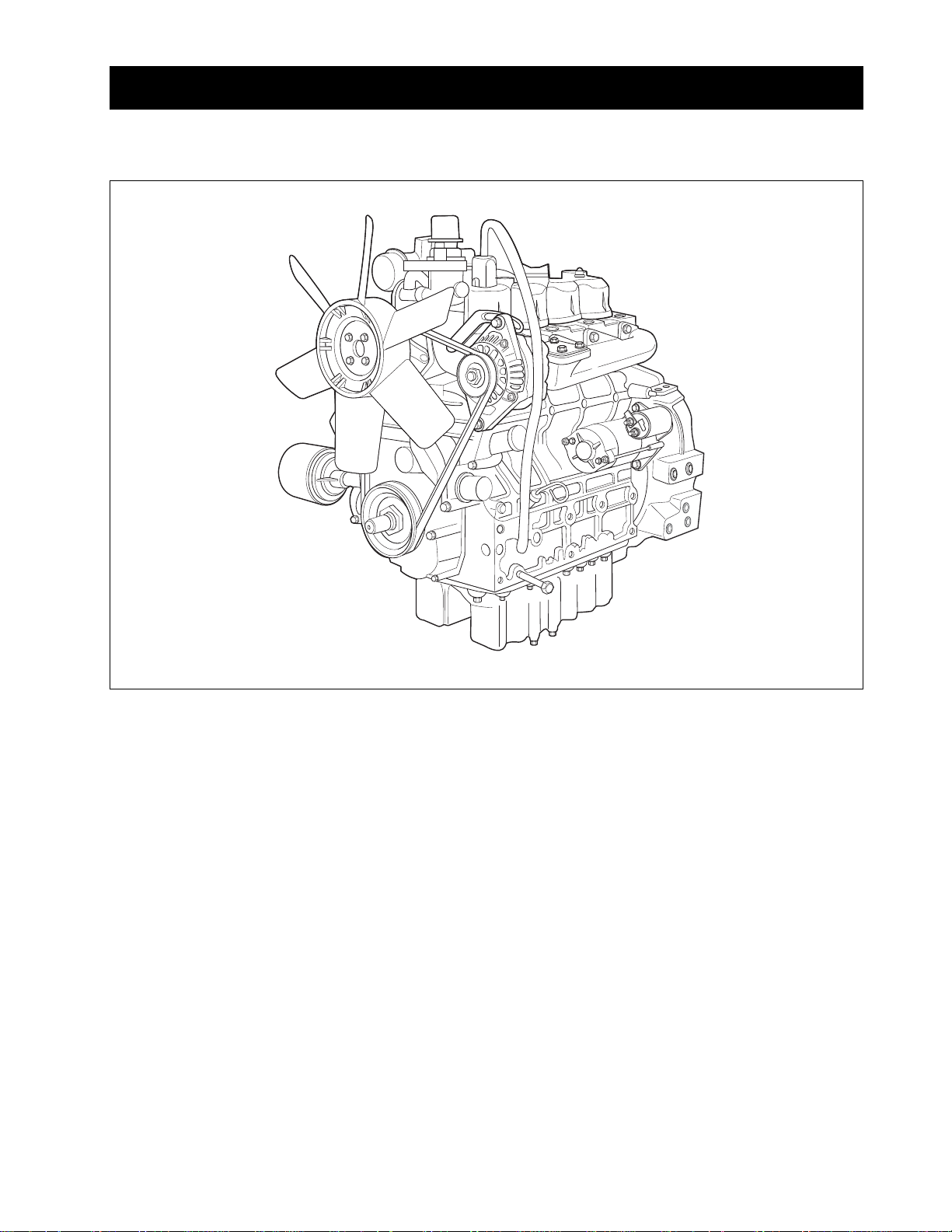
1.1 APPEARANCE
ENGINE
The DAEDONG A series engines are vertical, watercooled, 4-cycle, three or four cylinders diesel engines,
they concentrate DAEDONG’s foremost technologies.
With swirl combustion chamber, bosch K type fuel injection pump, well-balanced designs, they feature
greater power, low fuel consumption, less vibration and
noise, and low emission.
632W201A
2-3
Page 4
ENGINE
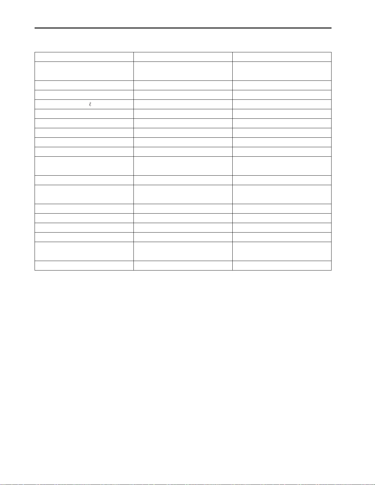
1.2 SPECIFICATIONS
MODEL
Type
Number of cylinder
Bore and stroke mm (in.)
Total displacement
(in3.)
Combustion chamber
POWER (NET) PS/rpm (kW. rpm)
Maximum idling speed rpm
Minimum idling speed rpm
Order of firing
Direction of rotation
Injection pump
Injection pressure
Injection timing (Before T.D.C)
Compression ratio
Fuel
Lubricant
Dimensions mm
(length x width x height) (in.)
Dry weight kg (kg, lbs.)
4A220
Vertical, water-cooled,
4-cycle diesel engine
4
87.0 x 92.4 (3.43 x 3.64)
2.197 (134.1)
vortex chamber
43/2,700 (30.9/2,700)
2,900
850 ~ 900
1-3-4-2
Counterclockwise
(viewed from flywheel side)
Bosch K TYPE mini pump
140 ~ 150 kgf/cm
2
(13.73 ~ 14.71 MPa, 1991 ~ 2133 psi)
18°
22 : 1
Diesel fuel
Engine oil SAE 15W-40
817.3 x 488.1 x 735.8
(32.2 x 19.2 x 29.0)
207 (456)
4A200T
Vertical, water-cooled,
4-cycle diesel engine (Turbo)
4
83.0 x 92.4 (3.27 x 3.64)
1.999 (122.0)
vortex chamber
47/2,600 (34.6/2,600)
2,800
850 ~ 900
1-3-4-2
Counterclockwise
(viewed from flywheel side)
Bosch K TYPE mini pump
140 ~ 150 kgf/cm
2
(13.73 ~ 14.71 MPa, 1991 ~ 2134 psi)
12°
22 : 1
Diesel fuel
Engine oil SAE 15W-40
817.3 x 542.0 x 735.8
(32.2 x 19.2 x 29.0)
211 (465)
* NOTE: Change of parts are not subject to advance notice.
2-4
Page 5
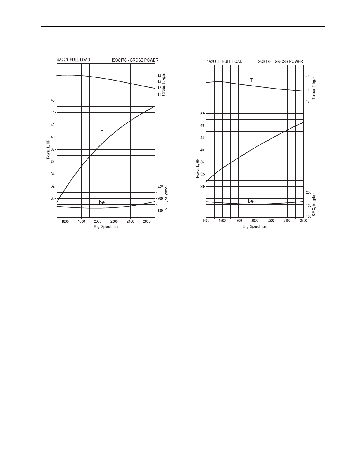
1.3 PERFORMANCE CURVE
ENGINE
632W204A 632W203A
2-5
Page 6
ENGINE
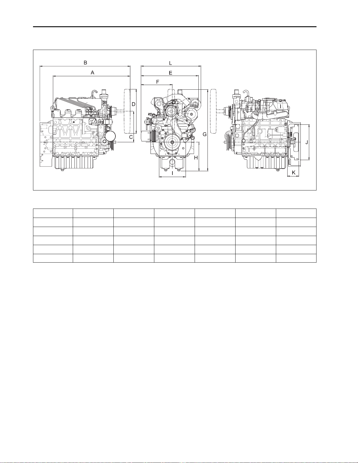
1.4 DIMENSIONS
632W205A
Sample/td Spec.
4A220
4A200T
4A220
4A200T
A
697.3 (27.45)
697.3 (27.45)
G
736 (28.98)
736 (28.98)
B
817.3 (32.18)
817.3 (32.18)
H
260 (10.24)
260 (10.24)
280 (11.02)
280 (11.02)
240 (9.45)
240 (9.45)
1.5 GENERAL WARNING
• When disassembling, arrange each part on a clean
place. Do not mix them up. Replace bolts and nuts
where they were.
• When connecting instruments to electrical
equipment, first disconnect battery negative
terminal.
• Replace gaskets or O-rings with new ones when
reassembling, and apply grease on a O-rings and
the oil seals when reassembling.
• When exchanging parts, use genuine DAEDONG
parts to maintain engine performance and safety.
• To prevent oil and water leakage, apply non-drying
adhesive to the gaskets according to this manual
before reassembling.
• When hoisting up the engine, use the hook provided on the cylinder head.
• When installing the engine, use the hook provided
on the cylinder head.
• When installing external cir-clips or internal cir-clips,
direct corner end to the non- loosening direction.
mm (in.)
C
I
D
φ
400 (15.75)
φ
400 (15.75)
J
φ
321 (12.64)
φ
321 (12.64)
E
502.6 (19.79)
519 (20.43)
K
104.5 (4.11)
104 (4.09)
F
262.5 (10.33)
282.4 (11.12)
L
-
542 (21.34)
2-6
Page 7
2. STRUCTURE AND FUNCTION
2.1 BODY
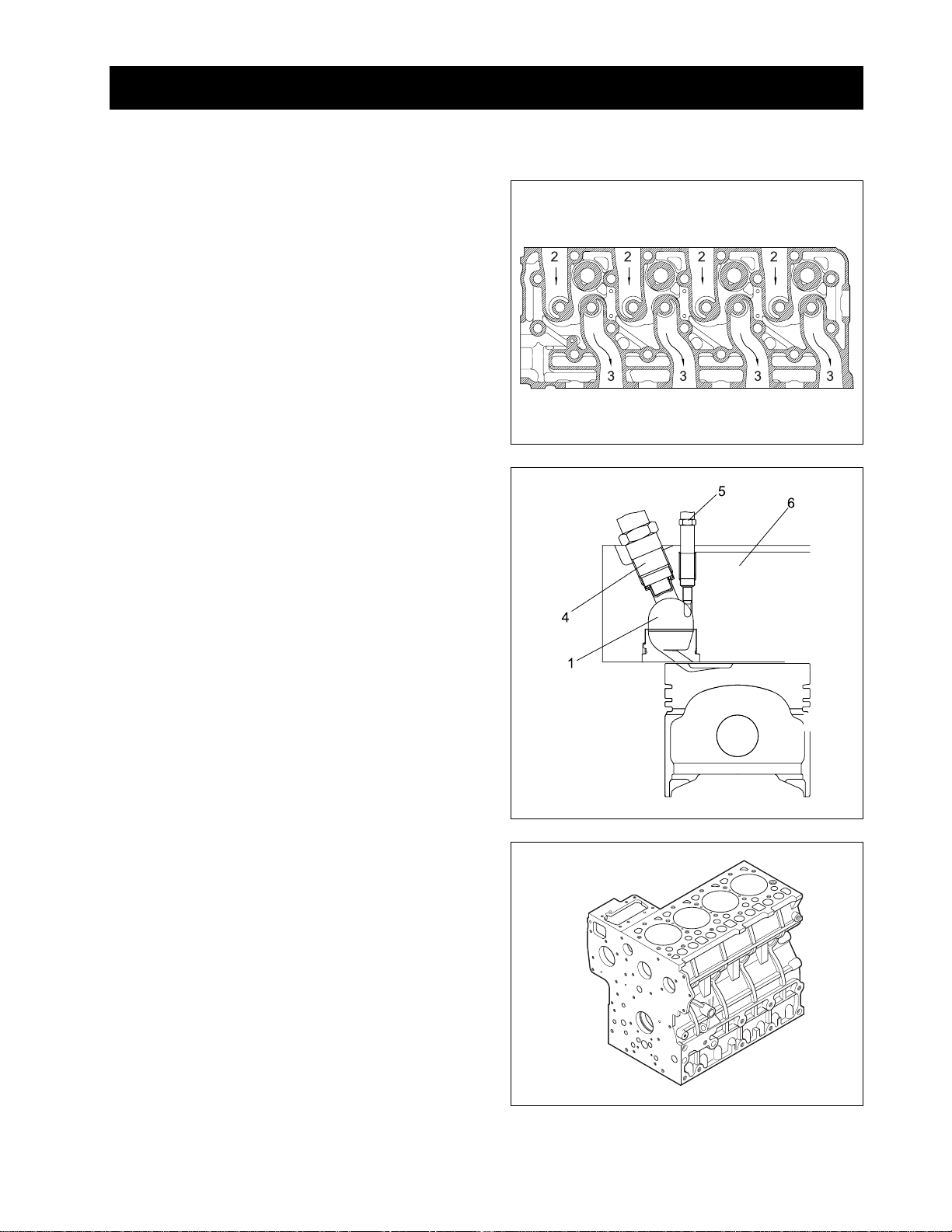
A . CYLINDER HEAD
The cylinder head is made of special alloy cast iron
which can resist high temperature and pressure
caused by combustion. The intake and exhaust ports
are arranged cross-flow type to get high combustion
efficiency by protecting the suction air from being heated
and expanded by heated exhaust air.
The Daedong vortex type combustion chamber is designed for high efficiency combustion and reducing fuel
consumption. The glow plugs assures easy engine
starts even at (-) 15 °C (5 °F).
(1) Combustion Chamber
(2) Inlet Port
(3) Exhaust Port
(4) Injection Nozzle
(5) Glow Plug
(6) Cylinder Head
ENGINE
632W206A
B. CYLINDER BLOCK
The engine has a high durability tunnel-type cylinder
block. Furthermore, liner less type, allows effective cooling, less distortion, and greater wear-resistance using
special material. The noise is reduced to a minimum
because each cylinder had its chamber.
632W207A
632W208A
2-7
Page 8
ENGINE
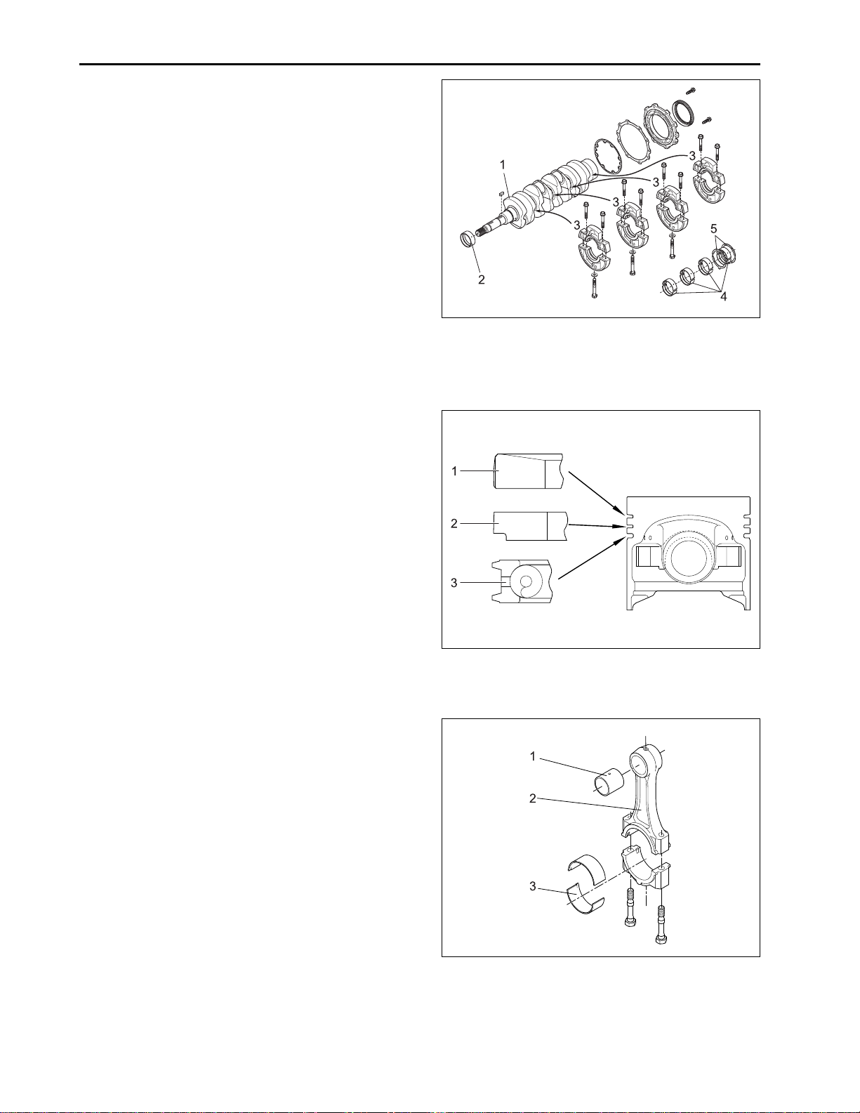
C. CRANKSHAFT
The crankshaft is made of forged steel and the journals,
the crankpins and the bearing surface for the oil seal
are induction-hardened to increase wear resistance.
Each crankshaft journal is supported by the main bearing case (3) having a bearing inside.
The front crankshaft bearing (2) is a solid type bushing
and rear and intermediate bearings are a split type.
The crankshaft’s bearings have oil holes for lubricant
flow.
D. PIST ON AND PISTON RINGS
The piston are made of an aluminum alloy which is
temperature and pressure resistant. Three rings installed in grooves of the piston. The top ring (1) is a
keystone type, which can withstand heavy loads, and
the barrel face on the ring fits well to the cylinder wall.
The second ring (2) is an undercut type, which prevents the oil from being carried up. The oil ring (3) has
chambered contact faces and an expander ring, which
increase the pressure of the oil ring against the cylinder wall to scrape the oil. The top ring is plated with
hard chrome to increase wear resistance (The ring of
4A200T engine is mode of a special steel).
632W209A
(1) Crankshaft (4) Crankshaft Bearing 2
(2) Crankshaft Bearing (5) Thrust Bearing
(3) Main Bearing Case
E. CONNECTING ROD
The connecting rod (2), which converts the reciprocating motion of the pistons caused by the fuel combustion into the rotating motion of the crankshaft, is made
of harden forged steel. The connecting rod has bearings at both ends. The small end has a solid type bearing (small end bushing (2)) and the big end has a split
type bearing (crankpin bearing (3)).
632W210A
(1) Top Ring (3) Oil Ring
(2) Second Ring
632W211A
(1) Small End Bushing (3) Crankpin Bearing
(2) Connecting Rod
2-8
Page 9
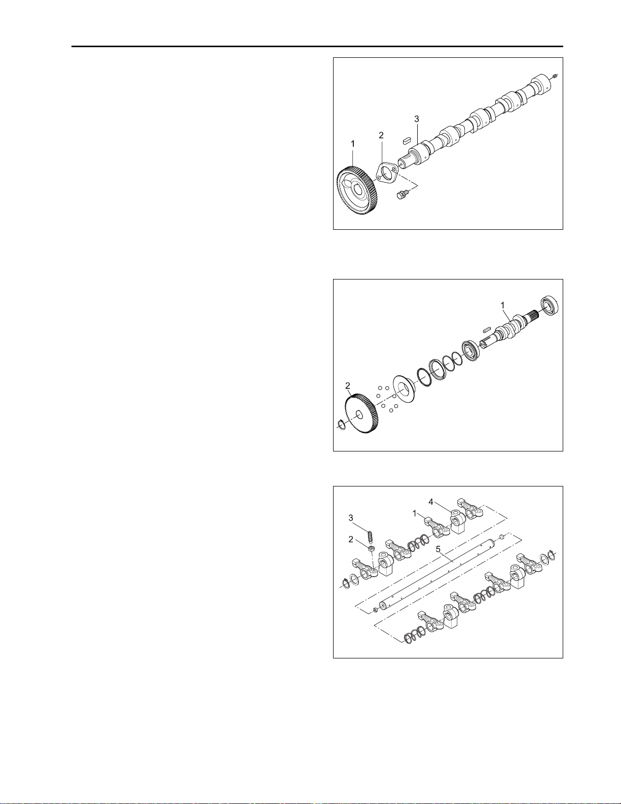
F. CAMSHAFT
The camshaft (3) is made of forged steel and it’s journals and cams are hardened to increase wear
resistance. The cams on the camshaft open and close
the intake and exhaust valves with the push rods and
rocker arms. The journals and their bearings are forcelubricated.
G. FUEL CAMSHAFT
This fuel camshaft is made of forged steel and its cams
are hardened and tempered to increase wear
resistance. The cams on the fuel camshaft (1) drive
the injection pump and the fuel transfer pump. The
governor balls are installed on the fuel camshaft to
control the engine speed.
ENGINE
632W212A
(1) Cam Gear (3) Camshaft
(2) Camshaft Stopper
H. ROCKER ARM ASSEMBLY
The rocker arm assembly includes the rocker arms (1)
and an adjusting screw (3), which is at the end of rocker
arm and rests on the push rod, rocker arm brackets (4)
and rocker arm shaft (5). The rocker arms are activated
by the reciprocating motion of the push rods and open
or close the intake and exhaust valves. The rocker arm
and other parts are lubricated through the drilled holes
of the brackets and the rocker arm shaft.
632W213A
(1) Fuel Camshaft (2) Injection Pump Gear
632W214A
(1) Rocker Arm (4) Rocker Arm Bracket
(2) Lock Nut (5) Rocker Arm Shaft
(3) Adjusting Screw
2-9
Page 10
ENGINE
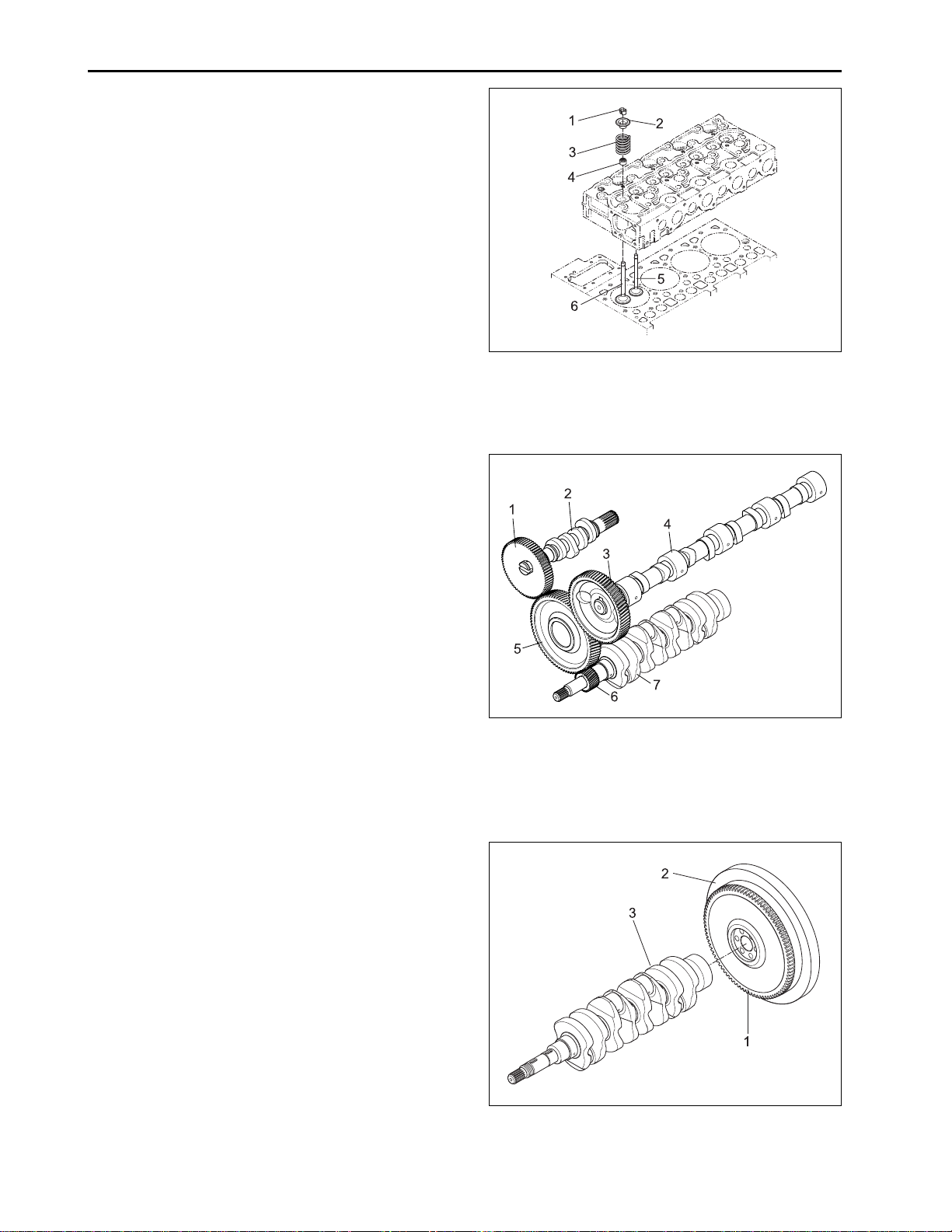
I. INTAKE AND EXHAUST V AL VES
The valve and its guide of the intake are different from
those for the exhaust. Other parts, such as the spring,
spring retainers, valve spring collets, valve stem seals
are the same for both the intake and the exhaust. All
contact or sliding surfaces are hardened to increase
wear resistance.
J. TIMING GEARS
The crankshaft drives the oil pump and the idle gear
engaged fuel camshaft and camshaft. The timing for
opening and closing the valves is extremely important
to achieve effective air intake and sufficient gas exhaust.
The appropriate timing can be obtained by aligning the
mark on the crankshaft gear (6) with one the idle gear
(5), idle gear with camshaft gear, idle gear with injection pump gear, when assembling.
632W215A
(1) Valve Spring Collet (4) Valve Stem Seal
(2) Valve Spring Retainer (5) Exhaust Valve
(3) Valve Spring (6) Intake Valve
K. FLYWHEEL
The flywheel is installed on the rear end of the
crankshaft. Its inertia keeps the engine turning at a
constant speed, while the crankshaft tends to speed
up during the power stroke and to slow down during
other stokes. The flywheel has a ring gear (1), which
meshes with the drive pinion of the starter.
The flywheel has marks “TC” and “FI” on its outer rim.
The mark TC shows the piston’s top dead center and
the mark FI shows the fuel injection timing, when they
are aligned with the mark of window on the clutch housing.
632W216A
(1) Injection Pump Gear (5) Idle Gear
(2) Fuel Camshaft (6) Crankshaft Gear
(3) Camshaft Gear (7) Crankshaft
(4) Camshaft
632W217A
(1) Ring Gear (3) Crankshaft
(2) Flywheel
2-10
Page 11
2.2 LUBRICATING SYSTEM
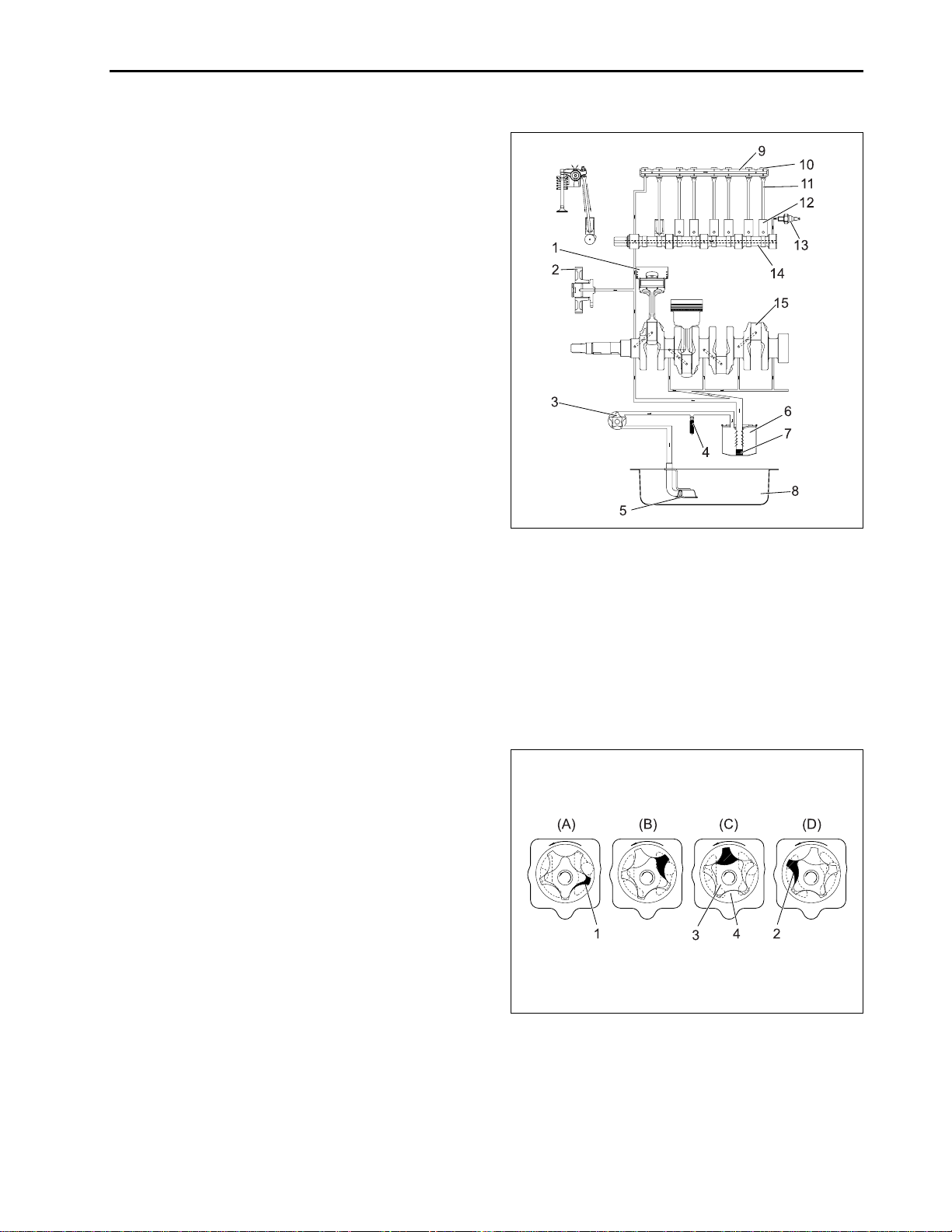
A. FLOW OF LUBRICATING OIL
The lubricating oil is forced to each journal through the
oil passages of the cylinder block, cylinder head and
shafts. The oil, splashed by the crankshaft or thrown
off from the bearings, lubricates other engine parts
such as the push rods (11), tappets (12), piston pins
and timing gears.
ENGINE
B. OIL PUMP
The oil pump is a gear type. Whose rotors have trochoid lobes. The inner rotor (3) has 4 lobes and the
outer rotor (4) has 5 lobes, and they are eccentrically
engaged to each other. The inner rotor, which is driven
by the crankshaft through the gears, rotates the outer
rotor in the same direction, varying the space between
the lobes.
While the rotors rotate from (A) to (B), the space leading to the inlet port increases, which causes the oil to
flow through the inlet port. When the rotors rotate to
(C), the port to which the space leads is changed from
inlet to outlet. At (D), the space decreases and oil is
discharged though the outlet port.
632W218A
(1) Piston (9) Rocker Arm Shaft
(2) Idle Gear (10) Rocker Arm
(3) Oil Pump (11) Push Rod
(4) Relief Valve (12) Tappet
(5) Strainer (13) Oil Pressure Switch
(6) Oil Filter Element (14) Camshaft
(7) Bypass Valve (15) Crankshaft
(8) Oil Pan
632W219A
(1) Inlet (3) Inner Rotor
(2) Outlet (4) Outer Rotor
2-11
Page 12
ENGINE
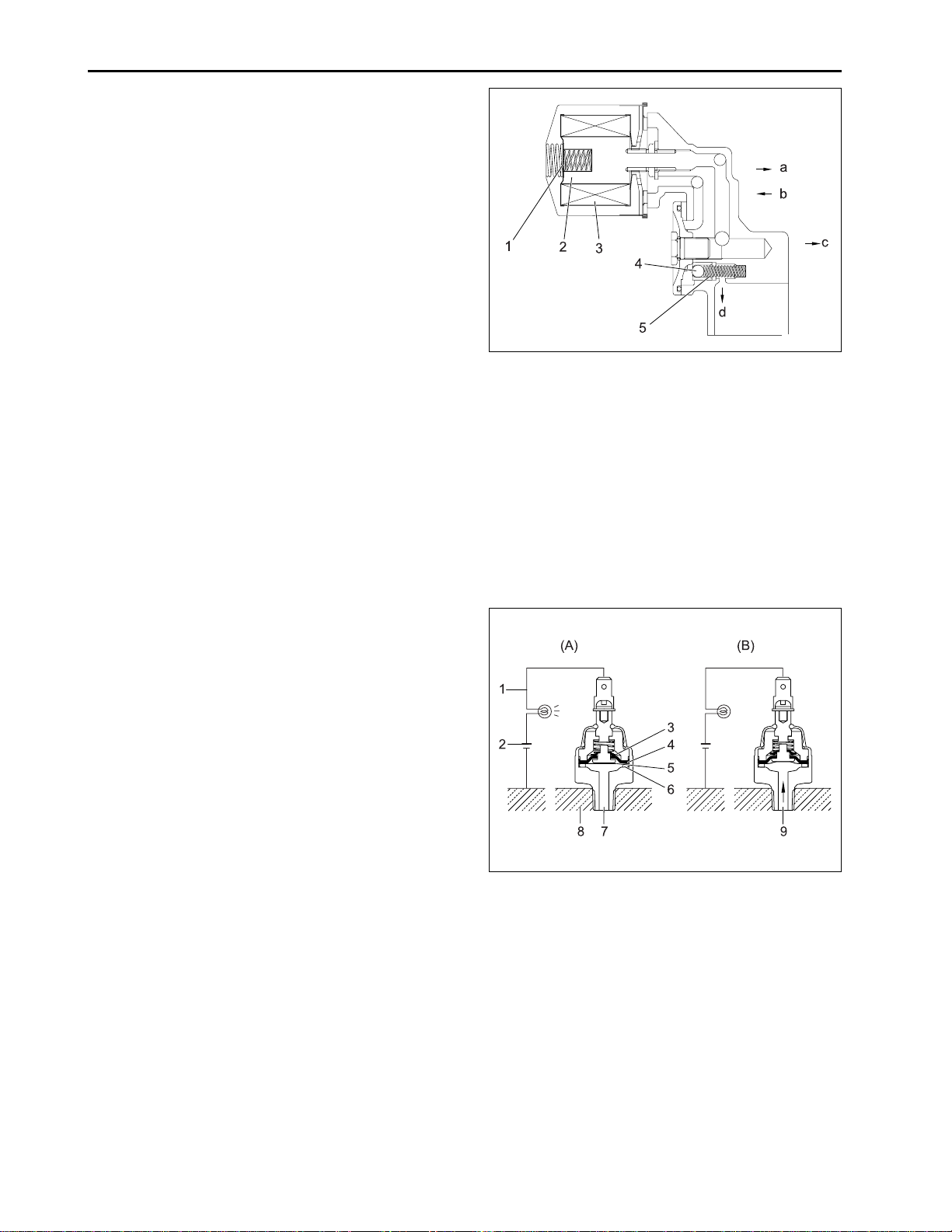
C. OIL FILTER AND RELIEF V ALVE
The lubricating oil force-fed by the pump is filtered by
the filter cartridge, passing through the filter element
from the outside to the inside. When the filter element
accumulates dirt and the pressure difference between
the inside and the outside rises more than 98 kPa
(1.0 kgf/cm
allow the oil to flow from the inlet line to outlet line,
bypassing the filter element. The relief valve ball (4) in
the inlet line allows oil to prevent damage to the lubricating system, when the oil pressure rises more than
441 kPa (4.5 kgf/cm
2
, 14 psi), the bypass valve (1) opens to
2
, 64 psi).
632W220A
(1) Bypass Valve
(2) Bypass Adjusting Spring
(3) Filter Element
(4) Relief Valve Ball
(5) Relief Adjusting Spring
(a) To Idle Gear, Camshaft and Rocker Arm
(b) From Oil Pump
(c) To Crankshaft Journal Crankpin
(d) Drain of Relief Valve
D. OIL PRESSURE SWITCH
The oil pressure switch is installed on the cylinder
block and leads to the oil passage of the lubricating
oil. When the oil pressure falls below the specified
value, the contacts of the oil pressure switch closes to
turn on the warning lamp (1).
632W221A
(A) At lower Oil Pressure
(49 kPa (0.5 kgf/cm
2
, 7 psi) or less)
(B) At Proper Oil Pressure
(1) Warning Lamp (6) Rubber washer
(2 ) Battery (7 ) Oil Pressure
(3) Contact Movable (8) Cylinder Block
(4) Cintact Cup (9) Pressure
(5) Diaphragm
2-12
Page 13
2.3 COOLING SYSTEM
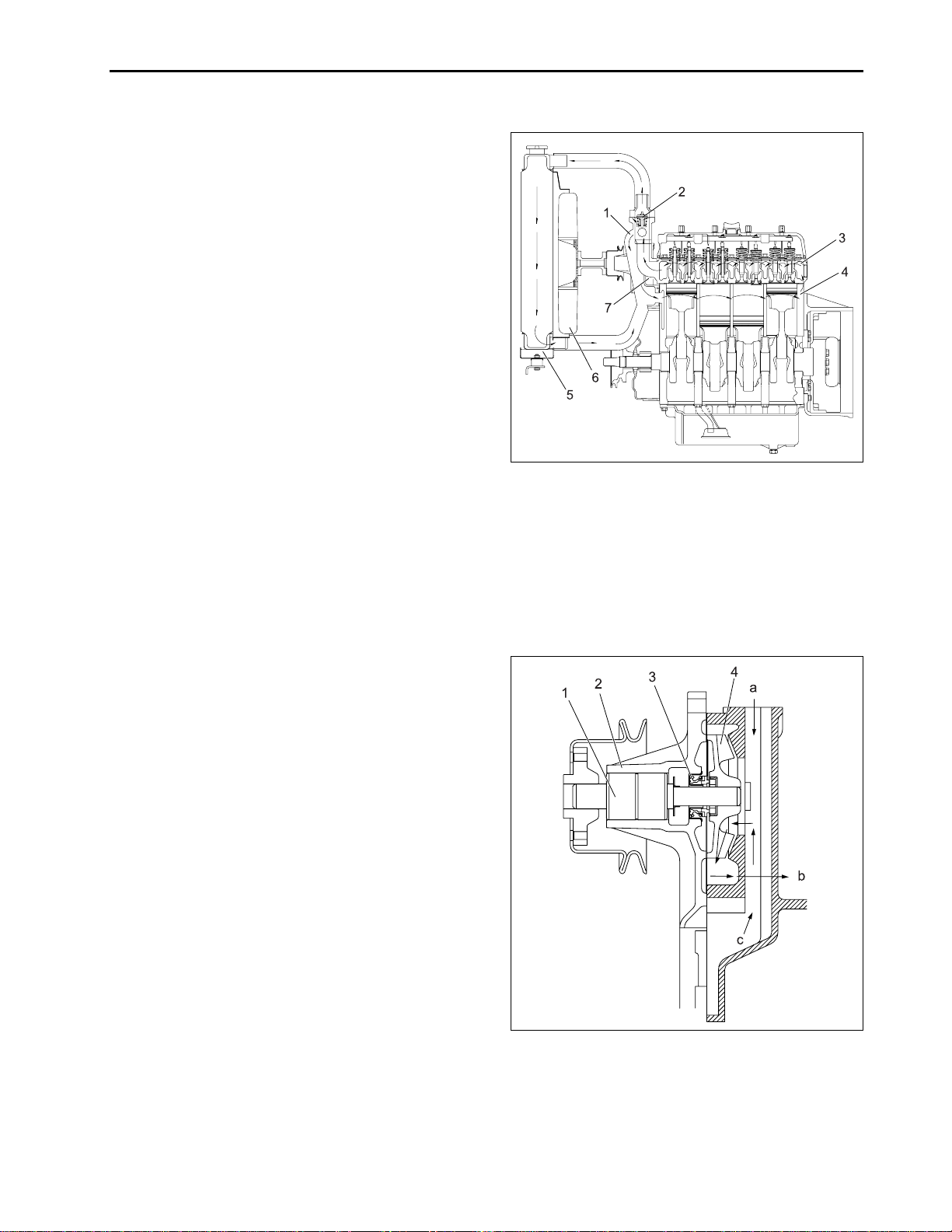
A. FLOW OF COOLING WATER
The cooling system consists of a radiator (5), a centrifugal water pump (7), a cooling fan (6) and a thermostat (2). The water is cooled as it flows through the
radiator core, and the fan behind the radiator pulls the
cooling air through the radiator core. The water pump
receives water from the radiator or from the cylinder
head and forces it into cylinder block. The thermostat
open or closes according to the water temperature.
When the water temperature is high, the thermostat
opens to allow the water to flow from the cylinder block
to the radiator. When the water temperature is low, the
thermostat closes and the flow stays within the block.
The opening temperature of the thermostat is approx.
70 °C (160 °F).
ENGINE
632W222A
(1) Water Return Pipe
(2) Thermostat
(3) Cylinder Head Water Jacket
(4) Cylinder Block Water Jacket
(5) Radiator
(6) Cooling Fan
(7) Water Pump
B. WA TER PUMP
The water pump is driven with the fan drive pulley, which
is on the water pump shaft and driven by the crankshaft
with a belt. The water pump sucks the cooled water,
forces into the cylinder block and draws out the hot
water to the radiator repeatedly. The mechanical seal
(3) prevents the water from entering the bearing (1).
632W223A
(a) From the Thermostat
(b) To the Cylinder Block
(c) From the Radiator
(1) Bearing (3) Mechanical Seal
(2) Pump Body (4 ) Pump Impeller
2-13
Page 14
ENGINE
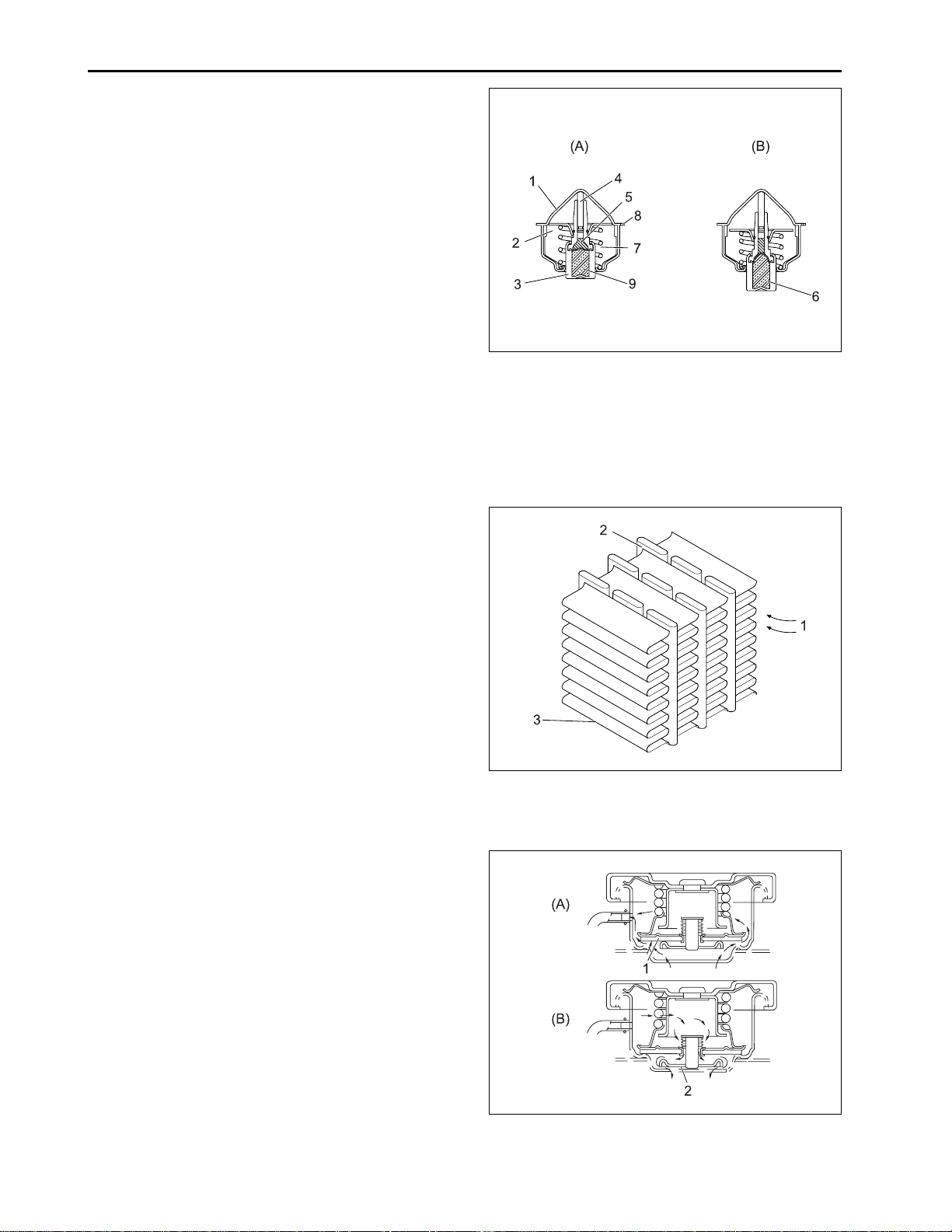
C. THERMOSTAT
The thermostat is wax pellet type, which controls the
flow of the cooling water to the radiator to keep the
proper temperature. The case has a seat (1) and the
pellet has a valve (2). The spindle attached to the case
is inserted into the synthetic rubber in the pellet. The
pellet is charged with wax.
(A) At low temperature (lower than 71 °C (160 °F)). The
valve (2) is seated by the spring (7) and the cooling
water circulates in the engine through the water return
pipe but does not enter the radiator.
(B) At high temperature (higher than 71 °C (160° F)). As
the water temperature rises, the wax in the pellet (3)
turns liquid and expands, repelling the spindle. The
pellet lowers and the valve (2) opens to send the cooling water to the radiator.
632W224A
(1) Seat (6) Wax (Solid)
(2) Valve (7) Spring
(3) Pellet (8) Leak Hole
(4) Spindle (9) Wax (Liquid)
(5) Synthetic Rubber
D. RADIATOR
The radiator core consists of water carrying tubes (2)
with fins (3) at a right angle to it. The water in the radiator is cooled by the air flowing through between the
tube wall and the fin.
E. RADIAT OR CAP
The pressure type cap is installed on the radiator, which
prevents the pressure difference between the inside
and the outside of the radiator from deforming the radiator.
(A) At high pressure
Higher than 88 kPa (0.9 kgf/cm
ant temperature rises and the pressure in the radiator
increase above the specified pressure, the pressure
valve (1) opens to reduce the internal pressure.
(B) At low pressure
When the coolant temperature falls and a vacuum is
formed in the radiator, the vacuum valve (2) opens to
allow coolant stored in the over flow tank to enter the
radiator.
2
, 13 psi) when the cool-
632W225A
(1) Cooling Air ( 3 ) Fin
(2) Tube
632W226A
(1) Pressure Valve ( 2) Vacuum Valve
2-14
Page 15
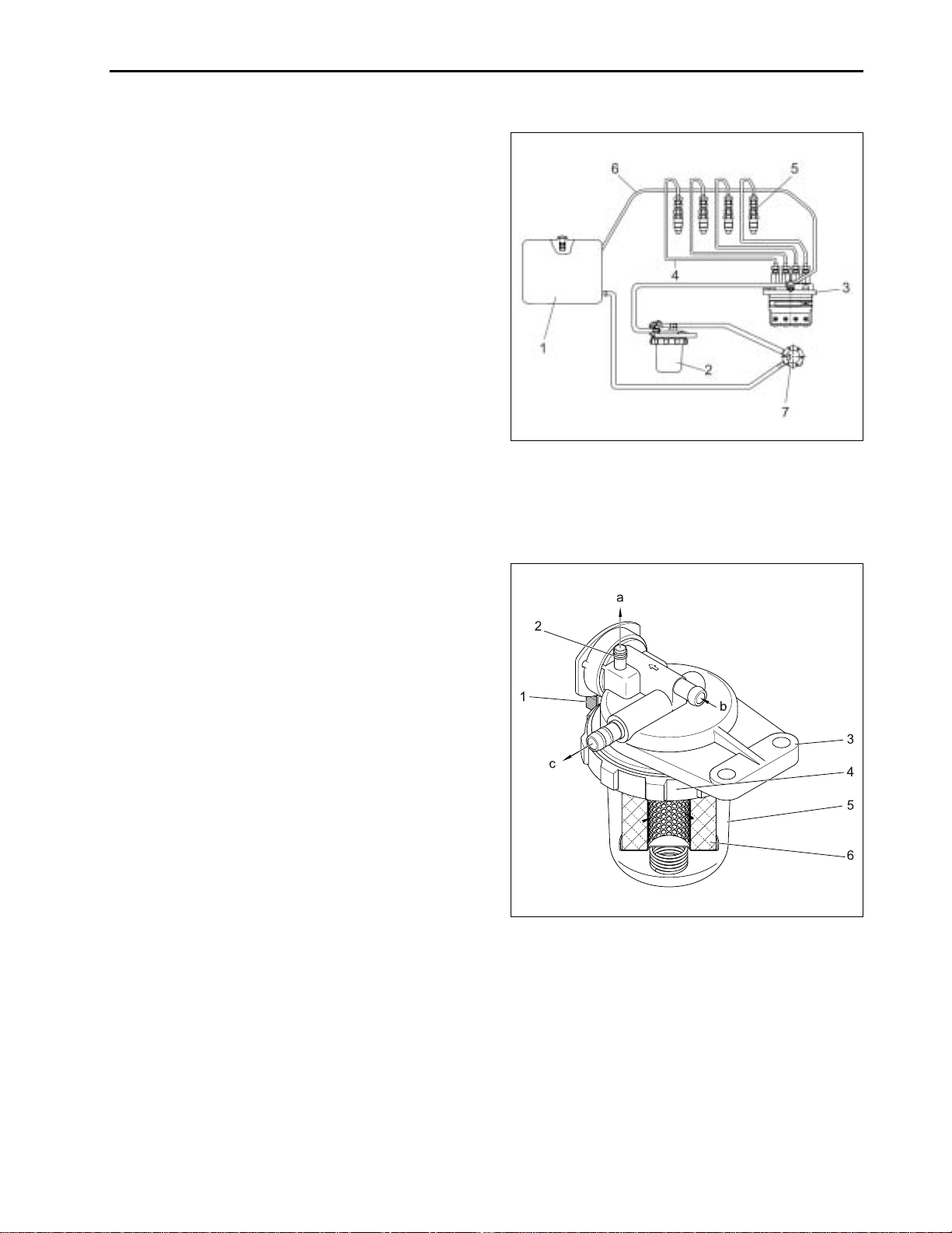
2.4 FUEL SYSTEM
A. FLOW OF FUEL
The fuel is fed from the fuel tank (1) through the fuel
feed pump (7) to the injection pump (3) thru the fuel
filter (2). The injection pump force-feds the fuel through
the injection nozzles (5), which inject the fuel into the
cylinders for combustion. The excessive fuel from the
injection pump to the injection nozzles is collected in
the fuel overflow pipes (6) and returns to the fuel tank.
ENGINE
632W227A
(1) Fuel Tank (5) Injection Nozzle
(2) Fuel Filter (6 ) Fuel Overflow Pipe
(3) Injection Pump (7) Fuel Feed Pump
(4) Injection Pipe
B. FUEL FILTER
The fuel filter removes dirt and water with its fine filter
paper, which collects particles of 90 microns (0.0034
in.) at 20 kPa (0.2 kgf/cm2, 3 psi). The fuel from the fuel
feed pump is filtered by the filter element (6), while
flowing through the filter body (3). The air vent (2) returns the air in the fuel to the fuel tank to prevent the
engine from stopping or running irregularly.
632W228A
(a) To Fuel Tank
(b) From Fuel Feed Pump
(c) To Injection Pump
(1) Cock (4) Retainer Ring
(2) Air Vent (5) Pot
(3) Filter Body (6) Filter Element
2-15
Page 16
ENGINE
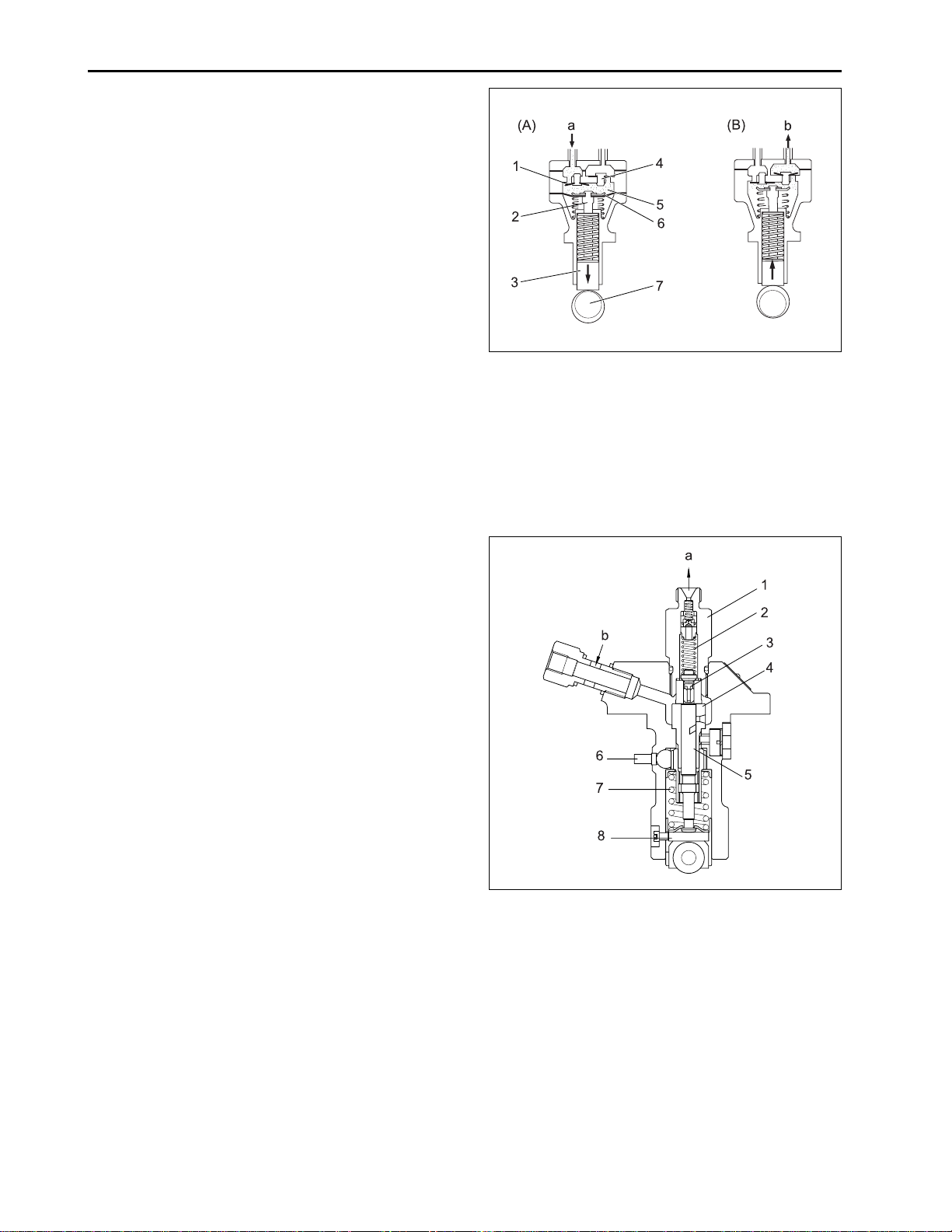
C. FUEL FEED PUMP
The diaphragm (6) is linked to the tappet (3) with a
push rod (2). The tappet is reciprocated by the eccentric cam on the fuel camshaft (7).
(A) Inlet stroke
When the diaphragm is pulled down by the spring,
vacuum in the chamber (5) causes the outlet valve (4)
to close and the atmospheric pressure in the fuel tank
forces the fuel into the chamber, opening the inlet valve
(1).
(B) Discharge stroke
When the diaphragm is pushed up by the cam, the
pressure in the chamber causes the inlet valve to close
and forces out the fuel, opening the outlet valve.
632W229A
(a) From Fuel Tank
(b) To Fuel Filter
(1) Inlet Valve (5) Chamber
(2) Push Rod (6) Diaphragm
(3) Tappet (7) Fuel Camshaft
(4) Outlet Valve
D. FUEL INJECTION PUMP
The injection pump is bosch K type mini injection
pump. It features a compact and light weight design.
632W230A
(a) To Injection Nozzle
(b) From Fuel Filter
(1) Delivery Valve Holder (5) Plunger
(2) Delivery Valve Spring (6) Control Rack
(3) Delivery Valve (7) Plunger Spring
(4) Cylinder (8) Tappet
2-16
Page 17
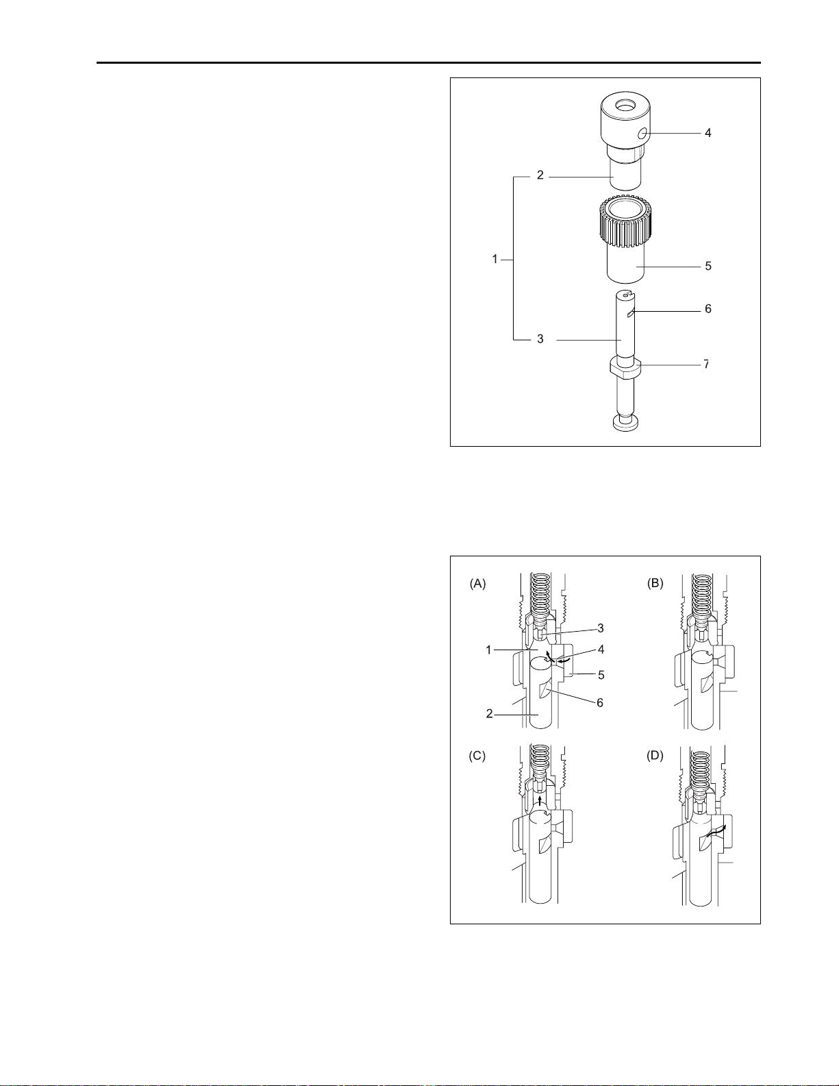
a. Pump Element
The pump element (1) consists of a plunger (3) and
cylinder (2), their sliding surfaces are precision machined to maintain fuel tightness. The plunger (3) fits
in the control sleeve (5) at the driving surface (7). The
sleeve is engaged with the control rack, which rotate
the plunger in the cylinder to control the amount of fuel
delivery.
ENGINE
632W231A
b. Operation of Pump Element
(A) Before delivery
As the taper lowers, the plunger (2) lowers and fuel is
drawn into the delivery chamber (1) through the feed
hole (4) from the fuel chamber (5).
(B) Beginning of delivery
When the plunger is pushed up by the cam and the
head of the plunger closes the feed hole (4), the pressure in the delivery chamber (1) rises to push the delivery valve (3) open.
(C) Delivery
While the plunger (2) is rising, delivery of fuel continues.
(D) End of delivery
When the plunger rises further and the control groove
(6) on its periphery meets the feed hole, the fuel returns to the fuel chamber (5) from the delivery chamber
(1) through the control groove (6) and the feed hole (4).
(1) Pump Element (5) Control Sleeve
(2) Cylinder (6) Control Groove
(3) Plunger (7) Driving Surface
(4) Feed Hole
632W232A
(1) Delivery Chamber (4) Feed Hole
(2) Plunger (5) Fuel Chamber
(3) Delivery Valve (6) Control Groove
2-17
Page 18
ENGINE
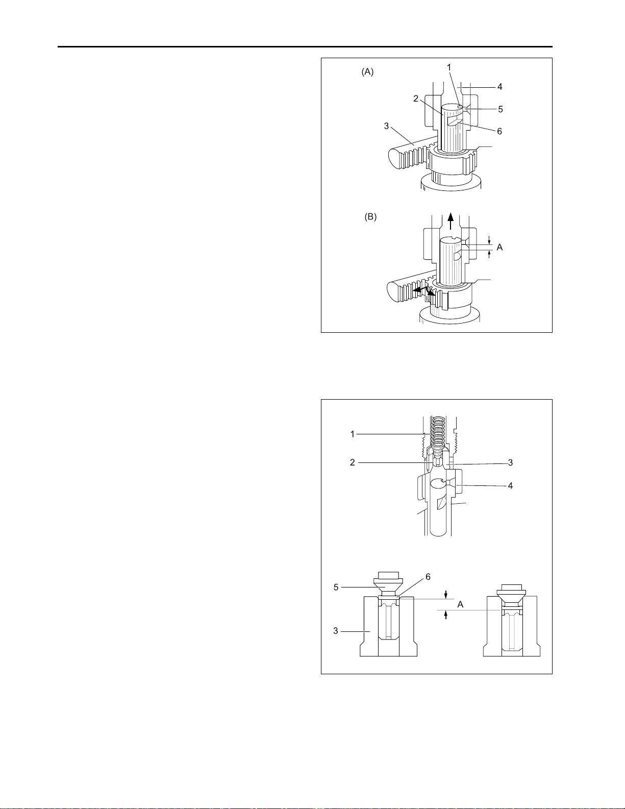
c. Amount of Fuel Delivery
(A) No fuel delivery
At the engine stop position of the control rack (3), the
lengthwise slot (1) on the plunger (2) aligns with the
feed hole (5). The delivery chamber (4) is led to the
feed hole during the entire stroke of the plunger. The
pressure in the delivery chamber does not build up
and no fuel is forced to the injection nozzle.
(B) Fuel delivery
The plunger is rotated by the control rack and the feed
hole is not aligned with the lengthwise slot. When the
plunger is pushed up, the feed hole is closed by the
plunger. The pressure in the delivery chamber builds
up and forces the fuel to the injection nozzle until the
control groove (6) meets the feed hole. The amount of
the fuel to be forced into the nozzle corresponds to
distance A.
632W233A
d. Delivery Valve
The delivery valve prevents the fuel in the injection pipe
from flowing back into the delivery chamber and the
fuel in the injection nozzle from dribbling after injection.
(1) Slot (4) Delivery Chamber
(2) Plunger (5) Feed Hole
(3) Control Rack (6) Control Groove
2-18
632W234A
(1) Valve Spring (4) Fuel Chamber
(2) Valve (5) Valve Face
(3) V alve Seal (6) Relief Plunger
Page 19
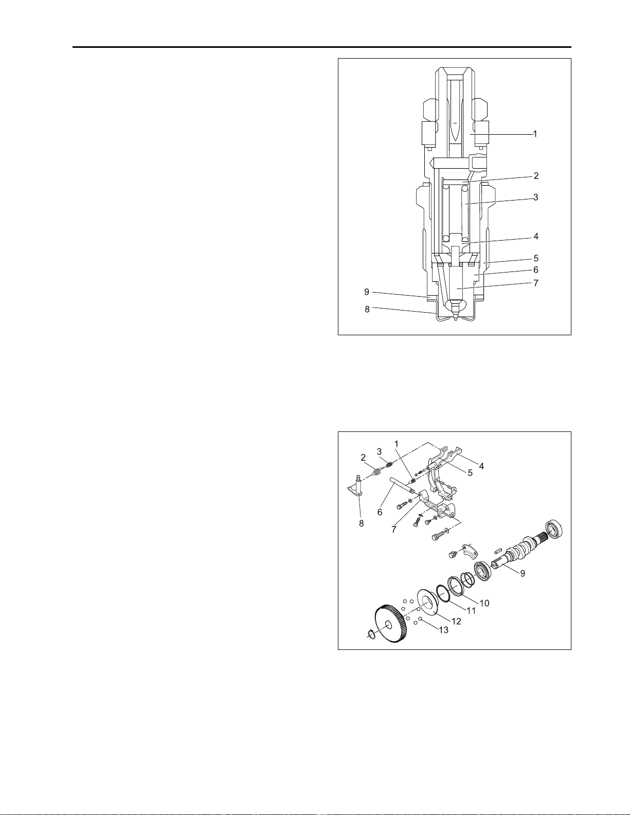
E. FUEL INJECTION NOZZLE
The nozzle is a throttle-type. It features low fuel consumption and works well with DAEDONG combustion
chamber. The nozzle valve opening pressure is about
13.7 to 14.7 MPa (140 to 150 kgf/cm
psi), the pressure overcomes the counterforce of nozzle
valve spring, and push the valve up instantly, the fuel is
then injected in a proper quantity into the swirling air in
the combustion chamber for combustion. Addition or
reduction of adjusting shims can adjust the opening
pressure. A washer of 0.1 mm corresponds to 980 kPa
(10 kgf/cm
2
, 142 psi) change in opening pressure. The
heat seal is employed to improve the durability and
reliability of the nozzle.
2
, 1,991 to 2,134
ENGINE
632W235A
F. GOVERNOR AND IDLE COMPENSATING
a. Disassembled View
The governor serves to keep engine speed constant by
automatically adjusting the amount of fuel supplied to
the engine according to changes in the load. The engine employs an all-speed governor which is controlled
by the centrifugal force of the steel ball (13) weights,
produced by rotation of the fuel camshaft (9), and tension of the governor spring 1 (2) and 2 (3) are balanced.
(1) Nozzle Holder Ass’y (6) Nozzle Body
(2) Adjusting Washer (7) Needle Valve
(3) Nozzle Spring (8 ) Heat Seal
(4) Push Rod (9) Packing
(5) Retaining Nut
632W236A
(1) Start Spring (8) Governor Lever
(2) Governor Spring 1 (9) Fuel Camshaft
(3) Governor Spring 2 (10) Governor Ball Case
(4) Fork Lever 1 (11) Steel Ball
(5) Fork Lever 2 (12) Governor Sleeve
(6) Fork Lever Shaft (13) Steel Ball
(7) Fork Lever Holder
2-19
Page 20
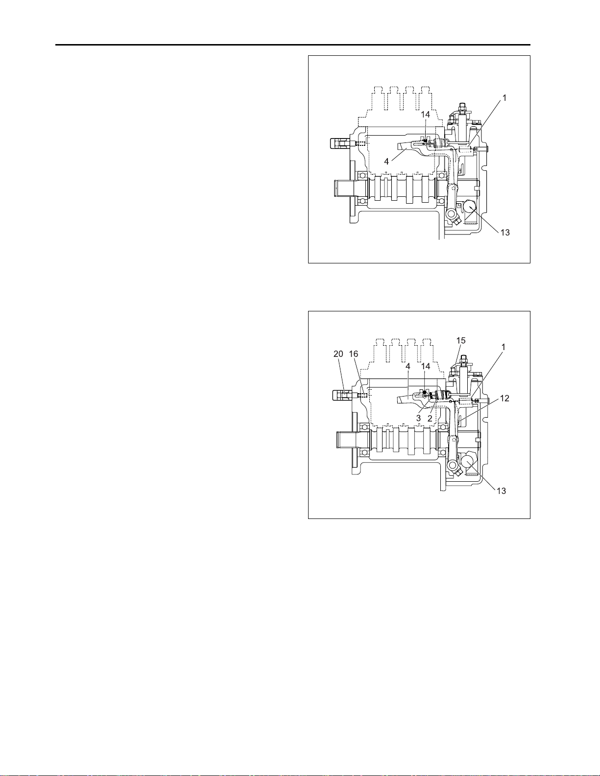
ENGINE
b. Operation of Governor
a) At start
The steel balls (13) have no centrifugal force. As the
fork lever 1 (4) is pulled by the start spring (1), the
control rack (14) moves to the maximum injection position. At start, the sufficient injection of the fuel enables
easy starting.
b) At idling
At the idling position of the speed control lever (15), the
governor spring 1 (2) is free and the governor spring 2
(3) only acts slightly. The governor sleeve (12) is
pushed leftward by a centrifugal force of steel ball (13).
Therefore, the fork lever 1 (4) and control rack (14) are
moved to the rear by the governor sleeve (12) and then
the idling adjusting spring (16) is compressed by the
control rack (14). As a result, the control rack (14) is
kept at a position where the centrifugal force of steel
ball (13) and forces of the start spring (1), governor
spring 2 (3) and idling limit spring are balanced, providing stable idling.
632W237A
(1) Start Spring (13) Steel Ball
(4) Fork Lever 1 (14) Control Rack
IMPORTANT:
• The idling speed has been factory-set. The idling
adjusting screw (20) and spring (16) should not be
disassembled and readjusted.
2-20
632W238A
(1) Start Spring (13) Steel Ball
(2) Governor Spring 1 (14) Control Rack
(3) Governor Spring 2 (15) Speed Control Lever
(4) Fork Lever 1 (16) Idle Adjusting Spring
(12) Governor Sleeve (20) Idle Adjusting Screw
Page 21
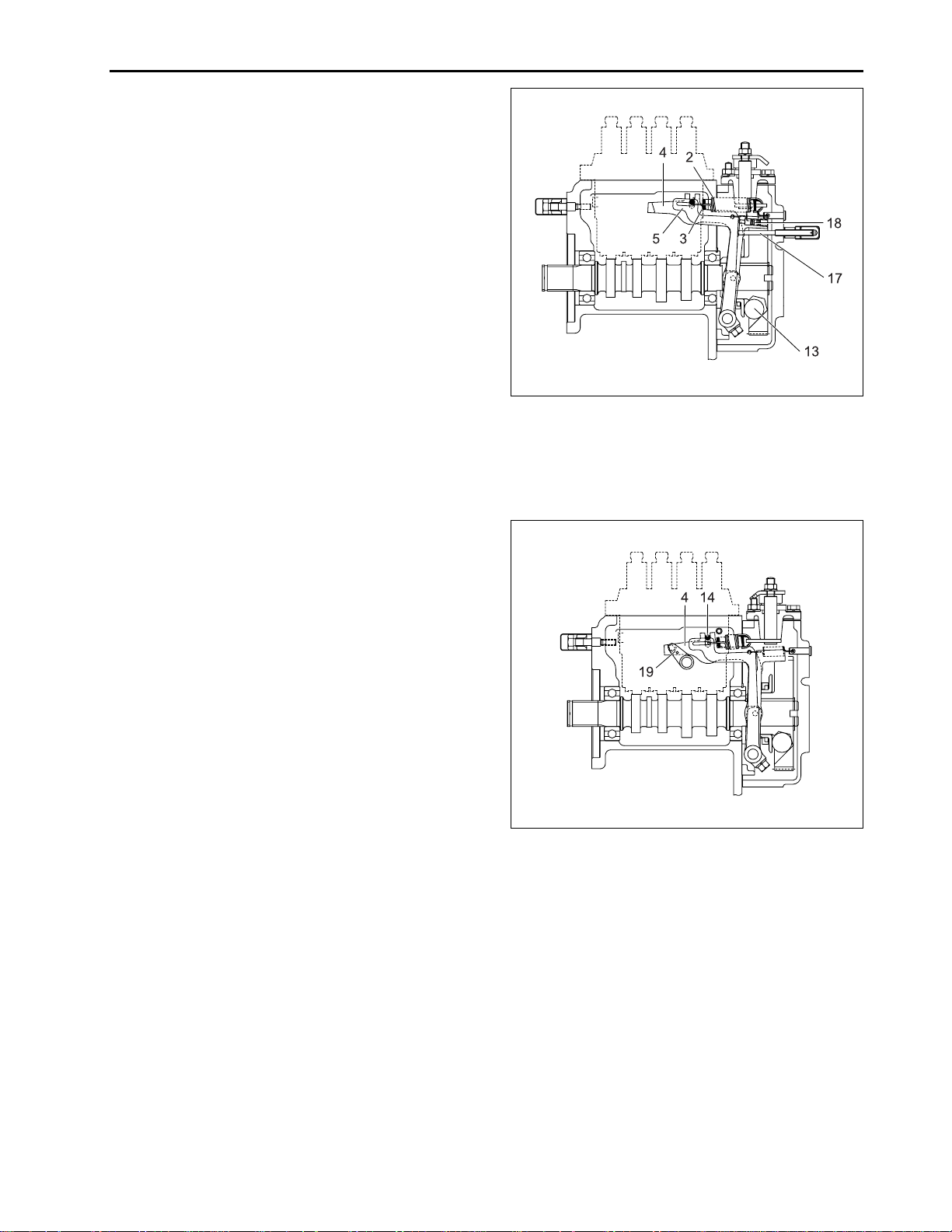
c) At High Speed Running with a Load
When a load is applied to an engine running at high
speed, the engine speed drops and the centrifugal force
of steel ball (13) becomes less, the fork lever 2 (5) is
pulled forward by the governor spring 1 (2) and 2 (3),
this increases the amount of fuel injected.
The fork lever 2 (5) becomes ineffective in increasing
the fuel injection when it is stopped by the adjusting
bolt (17). After that, when the force of torque spring (18)
becomes greater than the centrifugal force of the steel
balls, fork lever 1 (4) moves forward to increase fuel
injection, causing the engine to run continuously at a
high torque.
ENGINE
632W239A
(2) Governor Spring 1 (13) Steel Ball
(3) Governor Spring 2 (17) Adjusting Bolt
(4) Fork Lever 1 (18) Torque Spring
(5) Fork Lever 2
d) To stop engine
When the stop lever (19) is moved to the STOP position,
fork lever 1 (4) is moved rearward and the control rack
(14) is moved to the non-injection position, causing
the engine to stop.
632W240A
(4) Fork Lever 1 (19) Stop Lever
(14) Control Rack
2-21
 Loading...