

Page 1

MODEL 3700
FRONT FOLD EXPORT PLANTER
OPERATOR MANUAL
M0275-01 Rev. 10/18
This manual is applicable to: Model 3700 Front Folding Planters
24 Row 70 cm; 2016 Production and on
Record the model number and serial number of your planter along with date purchased:
Model Number ____________ ___________________
Serial Number ___________________________________
Date Purchased __________________________________
3700
Monitor Serial Number _______________________________________________
Measured Pulses Per Mile/Km (Radar Distance Sensor) ____________________
Measured Pulses Per Mile/Km (Magnetic Distance Sensor) _________________
SERIAL NUMBER
The serial number plate is located on the planter frame as shown below. The serial number provides important information
about your planter and is needed to obtain correct replacement parts. Always provide model number and serial number
to your Kinze Dealer when ordering parts or when contacting Kinze Manufacturing, Inc.
Serial number plate location -
2015 production
Kinze® and the Kinze® logo are registered trademarks of Kinze Manufacturing, Inc.
Page 2
Page 3
Page 4

Page 5

Predelivery/Delivery Checklist
Model 3700M0275-01
TO THE DEALER
Predelivery service includes assembly, lubrication, adjustment and test. This service helps ensure planter is delivered
to retail customer/end user ready for field use.
PREDELIVERY CHECKLIST
Use the following checklist after planter is completely assembled. Check off each item as it is found satisfactory or after
proper adjustment is made.
Row units properly spaced and optional attachments correctly assembled.
Row marker assemblies installed and adjusted at each end of the planter.
Vacuum and bulk fill components properly installed (as applicable).
All grease fittings in place and lubricated.
All working parts move freely, bolts are tight, and cotter pins are spread.
Check all drive chains for proper tension and alignment.
Check for oil leaks and proper hydraulic operation.
Hydraulic hoses correctly routed to prevent damage.
Inflate tires to specified air pressure and torque wheel lug bolts and lug nuts as specified in the Operator Manual.
All safety decals correctly located and legible. Replace if damaged.
All reflective decals and SMV sign correctly located and visible when the planter is in transport position.
Safety/warning lights correctly installed and working properly.
Paint all parts scratched during shipment or assembly.
All safety lockup devices on the planter and correctly located.
Auxiliary safety chain properly installed and hardware torqued to specification.
Vacuum fan PTO-driven pump correctly attached to tractor. Oil reservoir filled to capacity and system inspected for
leaks (If applicable).
Control box properly installed in tractor. All cables correctly routed and secure.
Planter has been thoroughly checked and to the best of my knowledge is ready for delivery to the customer.
(Signature of Set-Up Person/Dealer Name/Date)
OWNER REGISTER
Name Delivery Date
Street Address Model No. 3700 Serial No.
City, State/Province Dealer Name
ZIP/Postal Code Dealer No.
1/16
TM
Page 6

Predelivery/Delivery Checklist
M0275-01Model 3700
DELIVERY CHECKLIST
Use the following checklist at time planter is delivered as a reminder of very important information which should be
conveyed to retail customer/end user. Check off each item as it is fully explained.
Check proper operation of vacuum fan, bulk fill fan, and PTO-driven pump (If applicable) with tractor used with planter.
Life expectancy of this or any other machine is dependent on regular lubrication as directed in the Operator Manual.
All applicable safety precautions.
Along with retail customer/end user, check reflective decals and SMV sign are clearly visible with planter in transport
position and attached to tractor. Check safety/warning lights are in working condition. Tell retail customer/end user
to check federal, state/provincial, and local regulations before towing or transporting on a road or highway.
Give Operator Manual, Parts Manual, and all Instruction Sheets to retail customer/end user and explain all operating
adjustments.
Read warranty to retail customer/end user.
Complete Warranty and Delivery Report form.
To the best of my knowledge this machine has been delivered ready for field use and customer has been fully
informed as to proper care and operation.
(Signature of Delivery Person/Dealer Name/Date)
AFTER DELIVERY CHECKLIST
The following is a list of items we suggest to check during the first season of use of the equipment.
Check planter performance with retail customer/end user.
Check performance of vacuum or mechanical seed metering system with retail customer/end user.
Review importance of proper maintenance and adherence to all safety precautions with retail customer/end user.
Check for parts that may need to be adjusted or replaced.
Check all safety decals, reflective decals, and SMV sign are correctly located as shown in the Parts Manual and that
decals are legible. Replace if damaged or missing.
Check safety/warning lights are working properly.
(Signature of Follow-Up Person/Dealer Name/Date)
All registrations must be submitted online at “business.kinze.com” within 5 business days of delivery.
Retain a copy of this form for auditing purposes.
Tear Along Perforation
1/16
TM
Page 7

Table of Contents
Model 3700M0275-01
OVERVIEW
To The Owner ..................................1-1
Warranty ......................................1-3
General Information . . . . . . . . . . . . . . . . . . . . . . . . . . . . . . 1-4
Specifications. . . . . . . . . . . . . . . . . . . . . . . . . . . . . . . . . . . 1-5
General Safety Rules. . . . . . . . . . . . . . . . . . . . . . . . . . . . . 1-7
Safety Precautions. . . . . . . . . . . . . . . . . . . . . . . . . . . . . . . 1-8
MACHINE OPERATION
Planter Lift Safety Lockup .........................2-1
Row Marker Safety Lockup ........................2-1
Hitch Parallel Linkage Lockup ......................2-2
2-Speed Jack Assembly ..........................2-2
Initial Planter Preparation. . . . . . . . . . . . . . . . . . . . . . . . . . 2-3
Tractor Requirements. . . . . . . . . . . . . . . . . . . . . . . . . . . . . 2-5
Vacuum Tractor Mounted PTO Pump and
Planter Mounted Hydraulics .....................2-5
Tractor Preparation and Hookup ....................2-6
Transporting Planter. . . . . . . . . . . . . . . . . . . . . . . . . . . . . . 2-9
Cylinder Information. . . . . . . . . . . . . . . . . . . . . . . . . . . . . 2-10
Hydraulic Hose Information .......................2-11
Level Planter ..................................2-16
Contact Wheel Spring Adjustment. . . . . . . . . . . . . . . . . . 2-16
Contact Wheel Drive Sprockets . . . . . . . . . . . . . . . . . . . . 2-17
Seed Rate Transmission Adjustment . . . . . . . . . . . . . . . . 2-17
Wrap Spring Wrench Operation ...................2-18
Shear Protection ...............................2-18
Sliding Hitch Linkage . . . . . . . . . . . . . . . . . . . . . . . . . . . .2-19
Hydraulic/Electric Operation ......................2-20
Transport to Field Sequence ......................2-21
Field Operation ................................2-25
Field to Transport Sequence ......................2-26
Row Marker Operation ...........................2-30
Row Marker Speed Adjustment . . . . . . . . . . . . . . . . . . . . 2-31
Row Marker Chain Adjustment ....................2-32
Row Marker Length And Disc Blade Adjustment .......2-33
Vacuum System. . . . . . . . . . . . . . . . . . . . . . . . . . . . . . . . 2-34
Vacuum Fan Valve Block Assembly . . . . . . . . . . . . . . . . . 2-34
Analog Vacuum or Pressure Gauge. . . . . . . . . . . . . . . . . 2-34
Ag Leader Integra Display . . . . . . . . . . . . . . . . . . . . . . . .2-35
Ag Leader Monitoring Control Package (PMM) . . . . . . . . 2-35
Ag Leader InCommand 1200 Display ...............2-35
Point Row Clutches .............................2-37
Two-Speed Point Row Clutches. . . . . . . . . . . . . . . . . . . . 2-38
Piston Pump ..................................2-39
Check Valves . . . . . . . . . . . . . . . . . . . . . . . . . . . . . . . . . . 2-40
Low-Rate (Pop-Up) Liquid Fertilizer System ..........2-40
Rear Trailer Hitch (24 Row 70 CM Only) .............2-40
Field Test .....................................2-41
Field Check Seed Population. . . . . . . . . . . . . . . . . . . . . . 2-41
Determining Kilograms Per Hectare (Brush-Type Meter)
Determining Liters Per Hectare ....................2-42
Field Check Granular Chemical Application ..........2-43
Water Tank . . . . . . . . . . . . . . . . . . . . . . . . . . . . . . . . . . . .2-44
. . . . . 2-42
ROW UNIT OPERATION
Planting Depth . . . . . . . . . . . . . . . . . . . . . . . . . . . . . . . . . .3-1
“V” Closing Wheel Adjustment (Rubber or Cast Iron)
Closing Wheel Shield
(Rubber or Cast Iron “V” Closing Wheels) . . . . . . . . . . .3-1
Drag Closing Attachment. . . . . . . . . . . . . . . . . . . . . . . . . . 3-2
Covering Discs/Single Press Wheel Adjustment ........3-2
Seed Hoppers ..................................3-3
Seed Meter Drive Release. . . . . . . . . . . . . . . . . . . . . . . . . 3-3
Row Unit Extension Brackets. . . . . . . . . . . . . . . . . . . . . . . 3-3
Row Unit Chain Routing. . . . . . . . . . . . . . . . . . . . . . . . . . . 3-4
Quick Adjustable Down Force Springs Option
(Standard or Heavy Duty) .......................3-5
Pneumatic Down Pressure ........................3-6
Brush-Type Seed Meter . . . . . . . . . . . . . . . . . . . . . . . . . . .3-8
Finger Pickup Seed Meter . . . . . . . . . . . . . . . . . . . . . . . . .3-9
Vacuum Settings ...............................3-10
Seed Meter Cleanout. . . . . . . . . . . . . . . . . . . . . . . . . . . . 3-13
Additives .....................................3-14
Bayer Fluency Agent ............................3-15
Frame Mounted Coulter (Pull Row) .................3-16
Residue Wheels (Frame Mounted Coulter) ...........3-16
Row Unit Mounted Disc Furrower (Pull Row) .........3-17
Row Unit Mounted Residue Wheel .................3-18
Spiked Closing Wheel ...........................3-19
Row Unit Mounted No Till Coulter ..................3-20
Coulter Mounted Residue Wheels . . . . . . . . . . . . . . . . . . 3-20
Granular Chemical Hopper and Drive ...............3-21
Spring Tooth Incorporator ........................3-21
Granular Chemical Banding Options . . . . . . . . . . . . . . . .3-22
Granular Chemical Bander Shield . . . . . . . . . . . . . . . . . .3-22
.....3-1
RATE CHARTS . . . . . . . . . . . . . . . . . . . . . . . . . . . . 4-1
Rev. 10/18 i
TM
Page 8

Table of Contents
M0275-01Model 3700
LUBRICATION AND MAINTENANCE
Lubrication . . . . . . . . . . . . . . . . . . . . . . . . . . . . . . . . . . . . .5-1
Lubrication Symbols .............................5-1
Sealed Bearings ................................5-1
Wheel Bearings . . . . . . . . . . . . . . . . . . . . . . . . . . . . . . . . . 5-1
Drive Chains ...................................5-2
Bushings ......................................5-4
Sliding Hitch Linkage . . . . . . . . . . . . . . . . . . . . . . . . . . . . .5-4
PTO Shaft Coupling. . . . . . . . . . . . . . . . . . . . . . . . . . . . . . 5-5
Wrap Spring Wrench Assembly. . . . . . . . . . . . . . . . . . . . . 5-5
Liquid Fertilizer Piston Pump Crankcase Oil Level ......5-5
Grease Fittings .................................5-6
Mounting Bolts and Hardware .....................5-10
Tire Pressure . . . . . . . . . . . . . . . . . . . . . . . . . . . . . . . . . .5-11
Finger Pickup Seed Meter Inspection/Adjustment. . . . . . 5-13
Cleaning Finger Pickup Seed Meter For Storage ......5-14
Brush-Type Seed Meter Maintenance ...............5-15
Cleaning Brush-Type Seed Meter For Storage ........5-16
Vacuum Seed Meter Maintenance. . . . . . . . . . . . . . . . . . 5-18
Seed Meter Cleanout. . . . . . . . . . . . . . . . . . . . . . . . . . . . 5-18
Gauge Wheel Adjustment ........................5-19
Gauge Wheel Arm Pivot Spindle Replacement . . . . . . . . 5-19
Gauge Wheel Arm Bushing/Seal Replacement. . . . . . . . 5-20
15" Seed Opener Disc Blade/Bearing Assembly .......5-21
Seed Tube Guard/Inner Scraper ...................5-23
Frame Mounted Coulter .........................5-23
Residue Wheels
(For Use With Frame Mounted Coulter) ...........5-23
Spiked Closing Wheel ...........................5-24
Row Unit Mounted Disc Furrower ..................5-24
Row Unit Mounted No Till Coulter ..................5-25
Coulter or Row Unit Mounted Residue Wheels . . . . . . . .5-25
Granular Chemical Attachment ....................5-26
Spring Tooth Incorporator ........................5-26
Wrap Spring Wrench Cleaning and repair . . . . . . . . . . . . 5-26
Single and Two-Speed Point Row Clutch Maintenance
Planter Mounted Pump Drive and Oil Cooler. . . . . . . . . . 5-29
Digital Vacuum Gauge Adjustment .................5-29
Check Valve ...................................5-30
Dentent Lever Valve . . . . . . . . . . . . . . . . . . . . . . . . . . . . . 5-30
Flow Control Valves . . . . . . . . . . . . . . . . . . . . . . . . . . . . . 5-30
Pressure Relief Valves ...........................5-30
Relief Valve Cartridge ...........................5-30
Solenoid Valve . . . . . . . . . . . . . . . . . . . . . . . . . . . . . . . . . 5-31
Stroke Limiter Valve . . . . . . . . . . . . . . . . . . . . . . . . . . . . . 5-31
Chain Tension Adjustment . . . . . . . . . . . . . . . . . . . . . . . . 5-31
Stroke Limiter (Height Stop) Valve Adjustment ........5-32
. . . . 5-27
Detent Lever (Lowering Control) Valve Adjustment . . . . .5-33
Row Marker Bearing Lubrication or Replacement . . . . . . 5-34
Lift/Ground Drive Wheel Bearing
Repack or Replacement .......................5-35
Transport Wheel Bearing Replacement . . . . . . . . . . . . . . 5-36
Fertilizer Check Valve Cleaning and Repair ...........5-37
Piston Pump Storage. . . . . . . . . . . . . . . . . . . . . . . . . . . . 5-37
Low-Rate Liquid Fertilizer System . . . . . . . . . . . . . . . . . . 5-37
Pneumatic Down Pressure Air Compressor Tank ......5-37
Preparation for Storage ..........................5-38
Electrical Wiring Diagram for Light Package ..........5-39
Electrical Control Console Schematic ...............5-40
Electrical Wiring Harness Schematic (on tractor) ......5-41
Electrical Wiring Harness Schematic (on planter) . . . . . . 5-42
Valve Block - Located on Hitch ....................5-43
Valve Blocks - Located on Tower and R.H. Wing .......5-44
Control Console Schematic
(Optional Two-Speed Point Row Clutches) .........5-45
Electrical Wiring Harness Schematic
(Vacuum Fan Control) . . . . . . . . . . . . . . . . . . . . . . . . . 5-46
Hydraulic Hose Life .............................5-47
Hydraulic Schematic
(Vacuum Fan System) 24 Row 70 cm . . . . . . . . . . . . .5-49
Hydraulic System Schematic (24 Row 70 cm). . . . . . . . . 5-51
Hydraulic Valve Block Locations ...................5-53
Hydraulic Valve Block Functions ...................5-54
TROUBLESHOOTING
Closing Wheel ..................................6-1
Lift Circuit. . . . . . . . . . . . . . . . . . . . . . . . . . . . . . . . . . . . . . 6-1
Piston Pump ...................................6-1
Stroke Limiter Valve . . . . . . . . . . . . . . . . . . . . . . . . . . . . . . 6-2
PTO Pump Drive and Oil Cooler Option ..............6-4
Row Marker Operation ............................6-4
Seed Meter (Brush-Type). . . . . . . . . . . . . . . . . . . . . . . . . . 6-5
Solenoid Valve . . . . . . . . . . . . . . . . . . . . . . . . . . . . . . . . . . 6-5
Vacuum Seed Meter .............................6-6
Seed Meter (Finger Pickup) .......................6-8
ii Rev. 10/18
TM
Page 9
To The Owner
Model 3700M0275-01
Kinze Manufacturing, Inc. thanks you for your patronage. We appreciate your confidence in Kinze farm machinery. Your
Kinze planter has been carefully designed to provide dependable operation in return for your investment.
This manual has been prepared to aid you in the operation and maintenance of the planter. It should be
considered a permanent part of the machine and remain with the machine when you sell it.
It is the responsibility of the user to read and understand the Operator Manual in regards to safety, operation,
lubrication and maintenance before operation of this equipment. It is the user’s responsibility to inspect and service
the machine routinely as directed in the Operator Manual. We have attempted to cover all areas of safety, operation,
lubrication and maintenance; however, there may be times when special care must be taken to fit your conditions.
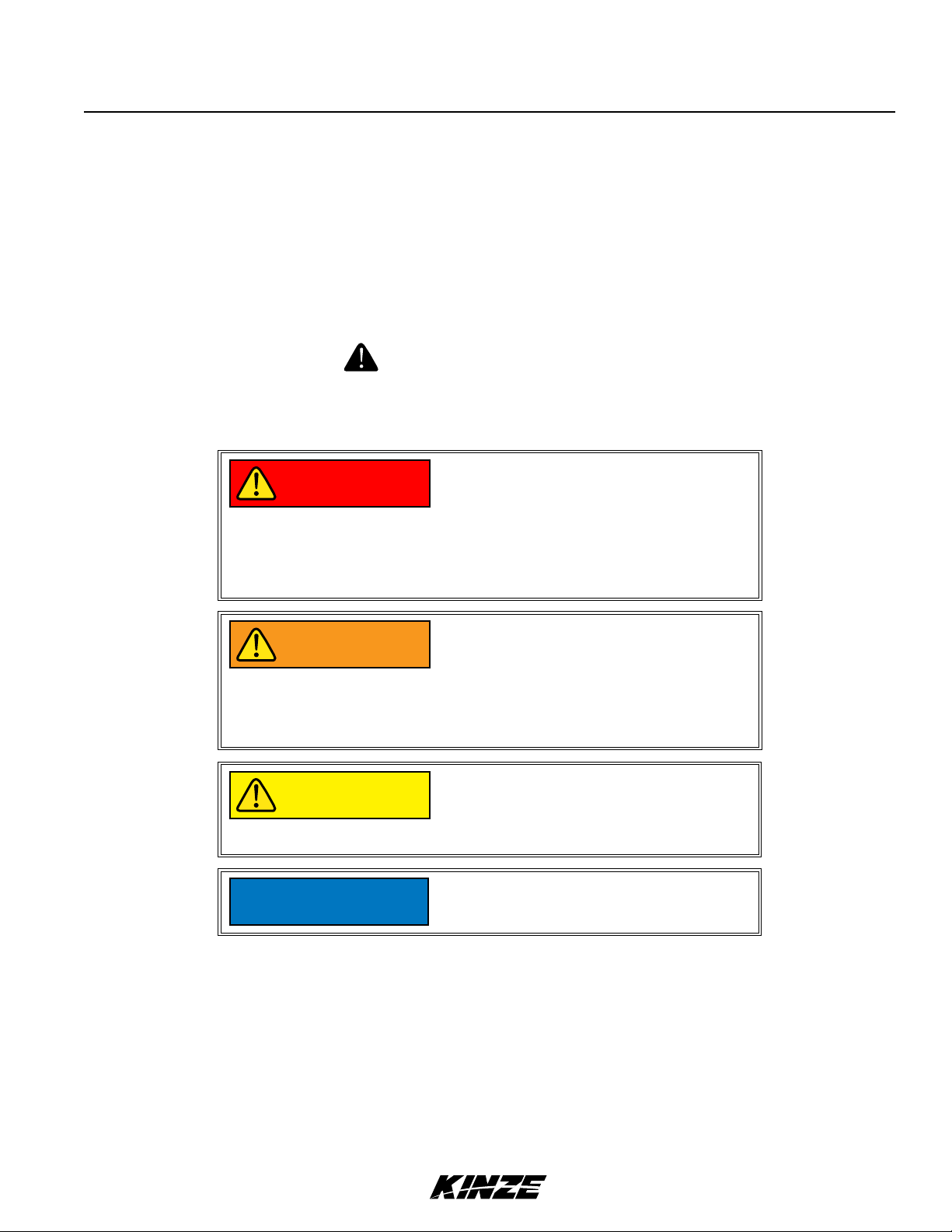
Throughout this manual the symbol and the words DANGER, WARNING, and CAUTION are used to call
attention to safety information that if not followed, will or could result in death or injury. NOTICE and NOTE are used to
call your attention to important information. The definition of each of these terms follows:
Indicates an imminently hazardous
DANGER
situation that, if not avoided, will
result in death or serious injury. This
signal word is to be limited to the most
extreme situations, typically for machine
components which, for functional
purposes, cannot be guarded.
Indicates a potentially hazardous
WARNING
CAUTION
NOTICE
NOTE: Special point of information or machine adjustment instructions.
situation that, if not avoided, could result
in death or serious injury, and includes
hazards that are exposed when guards
are removed. It may also be used to alert
against unsafe practices.
Indicates a potentially hazardous
situation that, if not avoided, may result
in minor or moderate injury. It may also
be used to alert against unsafe practices.
Used to address safety practices not
related to personal injury.
Rev. 10/18 1-1
TM
Page 10
To The Owner
M0275-01Model 3700
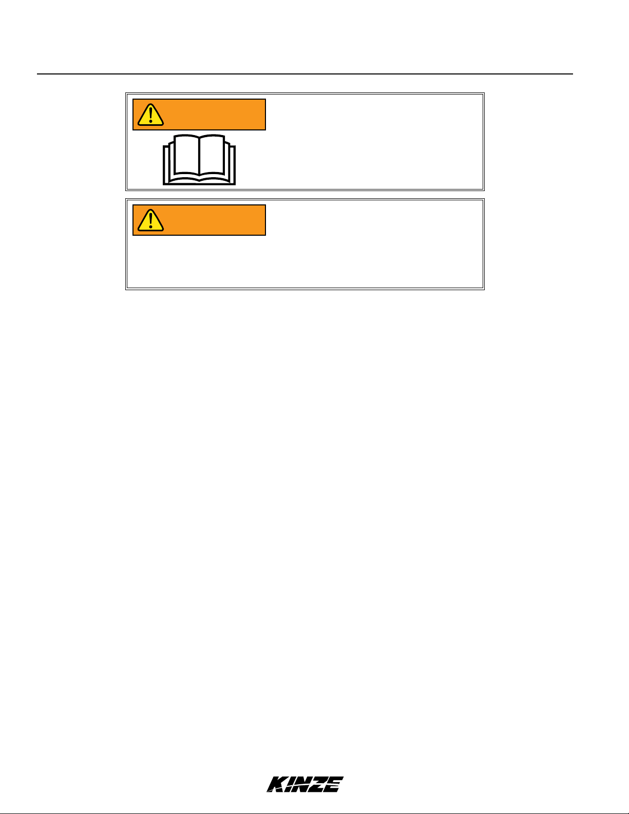
Improperly operating or working on
WARNING
WARNING
NOTE: Some photos in this manual may have been taken of prototype machines. Production machines may
vary in appearance.
this equipment could result in death
or serious injury. Read and follow all
instructions in Operator Manual before
operating or working on this equipment.
Some photos in this manual may show
safety covers, shields, or lockup devices
removed for visual clarity. NEVER
OPERATOR OR WORK ON machine
without all safety covers, shields, and
lockup device in place as required.
NOTE: Some photos and illustrations in this manual show optional attachments installed. Contact your Kinze
Dealer for purchase of optional attachments.
1-2 Rev. 10/18
TM
Page 11

Warranty
Model 3700M0275-01
The Kinze Limited Warranty for your new machine is stated on the retail purchaser’s copy of the Warranty And Delivery
Receipt form. Additional copies of the Limited Warranty can be obtained through your Kinze Dealer.
Warranty, within the warranty period, is provided as part of Kinze’s support program for registered Kinze products
which have been operated and maintained as described in this manual. Evidence of equipment abuse or modification
beyond original factory specifications will void the warranty. Normal maintenance, service and repair is not covered by
Kinze warranty.
To register your Kinze product for warranty, a Warranty And Delivery Receipt form must be completed by the Kinze
Dealer and signed by the retail purchaser, with copies to the Dealer, and to the retail purchaser. Registration must be
completed and submitted to Kinze Manufacturing, Inc. within 5 business days of delivery of the Kinze product to the
retail purchaser. Kinze Manufacturing, Inc. reserves the right to refuse warranty on serial numbered products which
have not been properly registered.
If service or replacement of failed parts which are covered by the Limited Warranty are required, it is the user’s
responsibility to deliver the machine along with the retail purchaser’s copy of the Warranty And Delivery Receipt to
the Kinze Dealer for service. Kinze warranty does not include cost of travel time, mileage, hauling or labor. Any prior
arrangement made between the Dealer and the retail purchaser in which the Dealer agrees to absorb all or part of this
expense should be considered a courtesy to the retail purchaser.
Kinze warranty does not include cost of travel time, mileage, hauling, or labor.
Rev. 10/18 1-3
TM
Page 12
General Information
M0275-01Model 3700
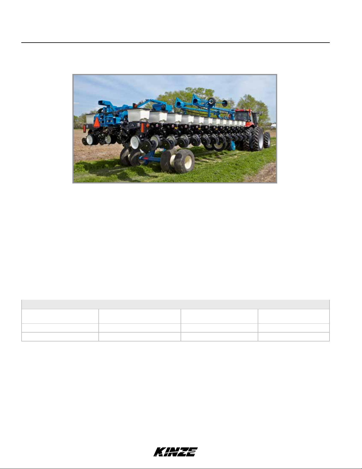
The Model 3700 Front Folding Planter is available in multiple sizes and row configurations with vacuum or mechanical
meters, conventional hoppers, and various other options. Contact your Kinze Dealer for additional details.
Model 3700 24 Row Conventional Planter
Information used in this manual was current at time of printing. However, due to Kinze’s ongoing product improvement,
production changes may cause your machine to appear slightly different in detail. Kinze Manufacturing, Inc. reserves
the right to change specifications or design without notice and without incurring obligation to install the same on
machines previously manufactured. To obtain the most recent version of your publication, please contact your Kinze
dealer.
Right hand (R.H.) and left hand (L.H.), as used throughout this manual, are determined by facing direction machine
travels in use unless otherwise stated.
TOOLS REQUIRED
Hardware Size / Tool Required
/" = /" /" = /"
(nut for /" hardware uses /" tool)
/" = /" /" = /" /" = 1/" 1/" = 2/"
/" = /" /" = /" 1" = 1/"
/" = 1/" 1/" = 1/"
1-4 Rev. 10/18
TM
Page 13

Specifications
Specifications
Specification Conventional Hoppers
Number of Rows 24R
Row Spacing 70 CM
Weight Empty** 18,298-19,996 lb (8300-9070 kg)
Axle Weight Empty* 13,199 lb (5987 kg)
Tongue Weight Empty* 5481 (2486 kg)
*Weight based off a typical configuration of a complete machine.
**Base machine weight depending on how machine is equipped (meters, drives, and hoppers).
Transport Height 11' 4" (3.50 m)
Planting Length 27' 3" (8.30 m)
Transport Length 32' 2" (9.80 m)
Planting Width 47' 11" (14.60 m)
Model 3700M0275-01
Transport Width
13' 1" (4.00 m)
With Granular Chemical Option: 14' 5" (4.40 m)
Seed Capacity
1.75 bu (62 L)/Hopper (Vacuum);
1.90 bu (67 L)/Hopper (Mechanical)
Transport Tire Size (4) 36 x 16-17.5 rib duplex 14-ply tubeless
Wing/Lift Tires (4 - 24R, 6 - 36R) 7.5" x 20", 8-ply, Tubeless Rib Implement
Contact Drive Tires (4) 4.80" x 8"
Piston Pump Drive Tires (Optional) (2) 7.60" x 15"
Field Lift Four Master/Two Slave Hydraulics
Row Markers
Independently controlled, three stage, low profile equipped disk blade depth
bands.
Rev. 10/18 1-5
TM
Page 14
Specifications
Tractor Hydraulic Requirements
Configuration Requirements Description
Base machine with mechanical meters 2 SCV 15 gpm
(57 L/min)
#1 SCV: planter lift
#2 SCV: markers / fold (with 12v control console)
M0275-01Model 3700
Base machine with vacuum meters
Tractor mounted PTO hydraulic pump
2 SCV 15 gpm
(57 L/min)
#1 SCV: planter lift
#2 SCV: markers / fold (with 12v control console)
NOTE: Tractor-mounted PTO hydraulic pump supplies oil flow for vacuum hydraulic circuit.
1-6 Rev. 10/18
TM
Page 15

General Safety Rules
Model 3700M0275-01
1. Read and understand instructions provided in this manual
and warning labels. Review these instructions frequently!
2. This machine is designed and built with your safety in mind.
Do not make any alterations or changes to this machine.
Any alteration to design or construction may create safety
hazards.
3. A large portion of farm accidents happen from fatigue
or carelessness. Safe and careful operation of tractor and
planter will help prevent accidents.
4.
Never allow planter to be operated by anyone unfamiliar
with operation of all functions of the unit. Operators must
read and thoroughly understand all instructions given in this
manual before operating or working on equipment.
5. Be aware of bystanders, particularly children! Always look
around to make sure it is safe to start tow vehicle engine or
move planter. This is particularly important with higher noise
levels and quiet cabs, as you may not hear people shouting.
6. Make sure planter weight does not exceed towing capacity
of tractor, or bridge and road limits. This is critical to maintain
safe control and prevent death or injury, or property and
equipment damage.
7. Never ride or allow others to ride on planter.
17. Make sure all safety/warning lights, SMV sign, and
reflective decals are in place and working properly before
transporting the machine on public roads.
18. Limit towing speed to 15 MPH (25 km/h). Tow only with
farm tractor of a minimum 90 HP. Allow for unit length when
making turns.
19. Reduce speed prior to turns to avoid the risk of
overturning. Always drive at a safe speed relative to local
conditions and ensure your speed is slow enough for a
safe emergency stop.
20. Chemical application is often an integral part of
planting. Follow label instructions for proper chemical
mixing, handling and container disposal methods.
21. Be familiar with safety procedures for immediate first
aid should you accidentally contact chemical substances.
22. Use the proper protective clothing and safety
equipment when handling chemicals.
23. Chemicals are supplied with Material Safety Data
Sheets (MSDS) that provide full information about the
chemical, its effects on exposure, and first aid needs in the
event of an emergency. Keep your MSDS file up-to-date
and available for first responders in case of emergency.
8. Store planter in an area away from human activity. DO
NOT permit children to play on or around the stored unit.
9. Keep hands, feet, and clothing away from moving parts.
Do not wear loose-fitting clothing which may catch in moving
parts.
10. Always wear protective clothing, shoes, gloves, hearing,
and eye protection applicable for the situation.
11. Do not allow anyone to stand between tongue or hitch
and towing vehicle when backing up to planter.
13. Prevent electrocution, other injuries, or property and
equipment damage. Watch for obstructions such as wires,
tree limbs, etc. when operating machine. Be aware of
clearances during turns and when folding/unfolding planter.
14. Reinstall all guards removed for maintenance activities.
Never leave guards off during operation.
15. Use of aftermarket hydraulic, electric, or PTO drives may
create serious safety hazards to you and people nearby. If
you install such drives, follow all appropriate safety standards
and practices to protect you and others near this planter from
injury.
16. Follow all federal, state/provincial, and local regulations
when towing farm equipment on a public highway. Use safety
chain (not an elastic or nylon/plastic tow strap) to retain
connection between towing and towed machines in the event
of primary attaching system separation.
24. When servicing ground engaging components such as
opening disks and firming points, use special care to avoid
points and edges worn sharp during use.
25. Use professional help if you are unfamiliar with working
on hydraulic systems. Pressurized hydraulic fluid can
penetrate body tissue and result in death, serious infection,
or other injuries.
Never pour waste onto the ground, down a drain, or into
any water source.
When disposing of waste such as oil, use leakproof
containers. Be sure to use containers that do not resemble
food or beverage which may mislead someone into
consuming them. Dispose of oil per your local, regional
requirements.
When disposing of any fertilizer chemicals used, contact
the supplier of the chemicals.
Model 3700 planter consists of 85% recyclable metals,
10% recyclable plastic and rubber, and 5% waste.
Rev. 10/18 1-7
TM
Page 16
Safety Precautions
M0275-01Model 3700
Following are some common hazard warnings associated with this equipment. Pay close attention to all safety,
operating, and maintenance information in this manual and decals applied to your equipment.
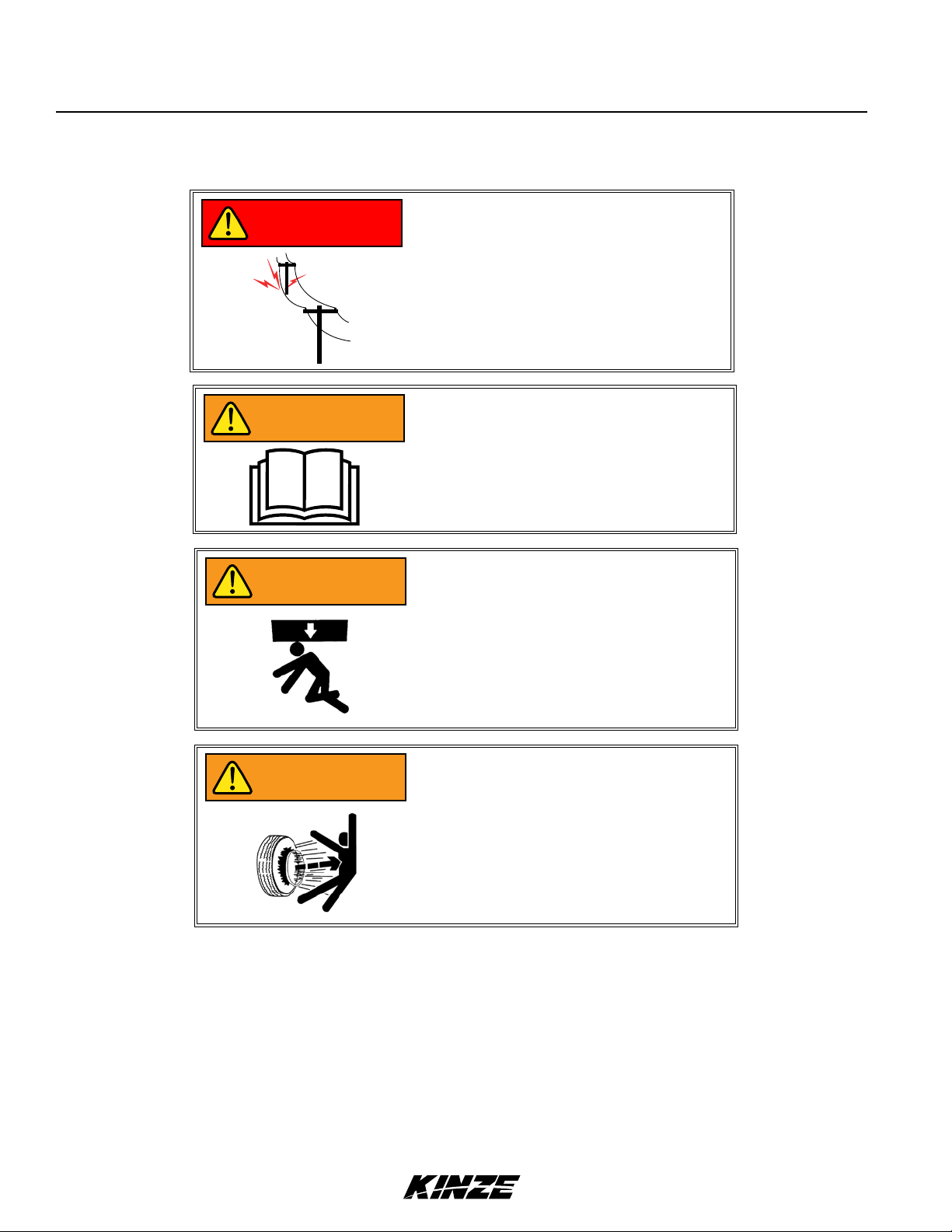
Contacting or coming close to power
DANGER
WARNING
lines or other high energy sources will
cause death or serious injury.
Keep away from power lines or high
energy sources at all times.
Improperly operating or working on
this equipment could result in death
or serious injury. Read and follow all
instructions in Operator Manual before
operating or working on this equipment.
WARNING
WARNING
Falling equipment can cause death or
serious injury. Install all lockup devices
or lower planter to ground before
working on equipment.
Explosive separation of rim and tire
parts can cause death or serious injury.
Overinflation, rim and tire servicing,
improper use of rims and tires, or worn
or improperly maintained tires could
result in a tire explosion.
1-8 Rev. 10/18
TM
Page 17

Safety Precautions
Model 3700M0275-01
SAFETY SIGNS AND DECALS
All safety/warning lights, reflective
WARNING
Safety signs and decals are placed on the machine to warn of hazards and provide important operating and maintenance
instructions. Information on these signs are for your personal safety and the safety of those around you. FOLLOW ALL
SAFETY INSTRUCTIONS!
• Keep signs clean so they can be easily seen. Wash with soap and water or cleaning solution as required.
• Replace safety signs if damaged, painted over, or missing.
decals, and SMV sign must be in place
and visible before transporting machine
on public roads or death, serious injury,
and damage to property and equipment
may result. Check federal, state/
provincial, and local regulations before
transporting equipment on public roads.
• Check reflective decals and SMV sign periodically. Replace if they show any loss of of reflective properties.
• When replacing decals, clean machine surface thoroughly with soap and water or cleaning solution to
remove all dirt and grease.
NOTE: Safety sign and decal locations are shown in the Parts Manual for this machine.
NOTE: Style and locations of SMV sign, reflective decals, and safety/warning lights conform to ANSI/ASABE
S279.14 JUL 2008 and ANSI/ASABE S276.6 JAN 2005.
Rev. 10/18 1-9
TM
Page 18

This page intentionally left blank.
Page 19
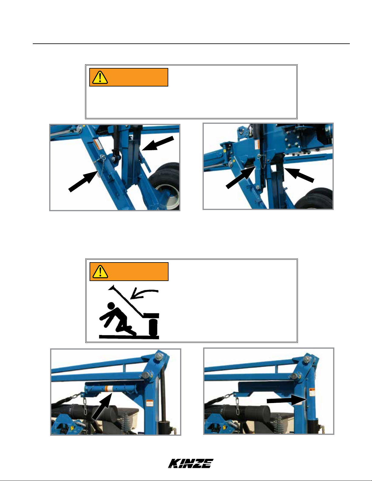
PLANTER LIFT SAFETY LOCKUP
WARNING
Machine Operation
Model 3700M0275-01
Uncontrolled machine movement can
crush or cause loss of control resulting
in death, serious injury, or damage to
property and equipment. Install all safety
lockup devices before working under or
transporting this equipment.
Safety lockup in storage position
Planter lift safety lockup is installed between lift cylinder and wheel lift arm. It is held in place by a pin and lynch pin.
Remove safety lockup and store on hose take-up for field operation.
Safety lockup in transport/maintenance position
ROW MARKER SAFETY LOCKUP
Row marker can lower at any time and
WARNING
could cause death or serious injury. Stay
away from row markers! Install safety
lockup device when not in use.
Row marker safety lockup stored
Always install row marker lockups when working on, storing, or transporting planter. Hold in place with two clevis pins.
Rev. 10/18 2-1
Row marker safety lockup installed
TM
Page 20

WARNING
WARNING
HITCH PARALLEL LINKAGE LOCKUP
Machine Operation
M0275-01Model 3700
Planter hitch may raise uncontrollably
during folding/unfolding and can cause
death, serious injury, or damage property
and equipment. DO NOT fold or unfold
planter without planter attached to a
tractor. DO NOT unhitch planter from
tractor unless fully folded for transport
or fully unfolded with planting units
lowered to ground.
Uncontrolled movement of equipment
can cause loss of control and could
result in death, serious injury, or damage
to property and equipment. Install
all safety pins before transporting
equipment.
Hitch parallel linkage pin stored
A hitch parallel linkage lock pin locks hitch parallel linkage in raised (transport) position.
Hitch parallel linkage pin installed
2-SPEED JACK ASSEMBLY
Slow
Fast
Jack handle stored
Store jack on L.H. side of hitch. Secure in place with spring pin. Install jack on hitch post and secure in place with
spring pin. Pull out on handle for high speed or push in on handle for low speed operation.
2-2 Rev. 10/18
TM
Jack handle installed
Page 21
Machine Operation
Model 3700M0275-01
Improperly operating or working on
WARNING
this equipment could result in death
or serious injury. Read and follow all
instructions in Operator Manual before
operating or working on this equipment.
INITIAL PLANTER PREPARATION
Following information is general in nature to aid in preparation of tractor and planter for use, and to provide general
operating procedures. Operator experience, familiarity with the machine, and the following information should combine
for efficient planter operation and good working habits.
Explosive separation of rim and tire
WARNING
parts can cause death or serious injury.
Overinflation, rim and tire servicing,
improper use of rims and tires, or worn
or improperly maintained tires could
result in a tire explosion.
WARNING
Wheel separation can cause loss of
control resulting in death, serious injury,
or damage to property and equipment.
Check lug nuts on transport wheels are
tight before operating planter for first
time and periodically after.
Rev. 10/18 2-3
TM
Page 22
Machine Operation
M0275-01Model 3700
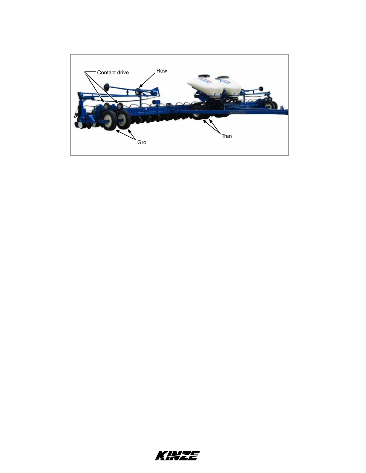
Contact drive
Ground drive
Row marker
Transport
Tire locations (L.H. mirrors R.H. shown)
1. Torque transport wheel ¾"- 16 lug nuts to 244 Nm.
2. Inflate tires to the following specifications:
• Ground drive (wings) - 225 x 70R 22.5. . . . . . . . . . . . . . . . . . . 75 PSI (517 kPa)
• Transport - 36" x 16" x 17.5" . . . . . . . . . . . . . . . . . . . . . . . . . . . 75 PSI (517 kPa)
• Contact drive - 4.80" x 8" .............................50 PSI (345 kPa)
• Row marker - 16" x 6.5" x 8". . . . . . . . . . . . . . . . . . . . . . . . . . . . 14 PSI (97 kPa)
• Liquid fertilizer piston pump (Not shown) - 4.10" x 6" ........50 PSI (345 kPa)
3. Lubricate planter and row units per lubrication information in this manual.
4. Check all drive chains for proper tension, alignment, and lubrication.
2-4 Rev. 10/18
TM
Page 23
Machine Operation
Model 3700M0275-01
TRACTOR REQUIREMENTS
All Hydraulic Requirements: Minimum
NOTICE
Consult your dealer for information on horsepower requirements and tractor compatibility. Requirements vary with planter
options, tillage, and terrain.
Two dual remote hydraulic outlets (SCV) are required on all sizes of conventional planters equipped with row markers.
Four dual remote hydraulic outlets (SCV) are required on all sizes of bulk fill planters equipped with row markers. A 12
volt DC electrical system is required on all sizes.
Pressure 2350 PSI (16200 kPa); Maximum
Pressure 3000 PSI (20700 kPa). Check
tractor hydraulics to ensure that
maximum pressure cannot be exceeded.
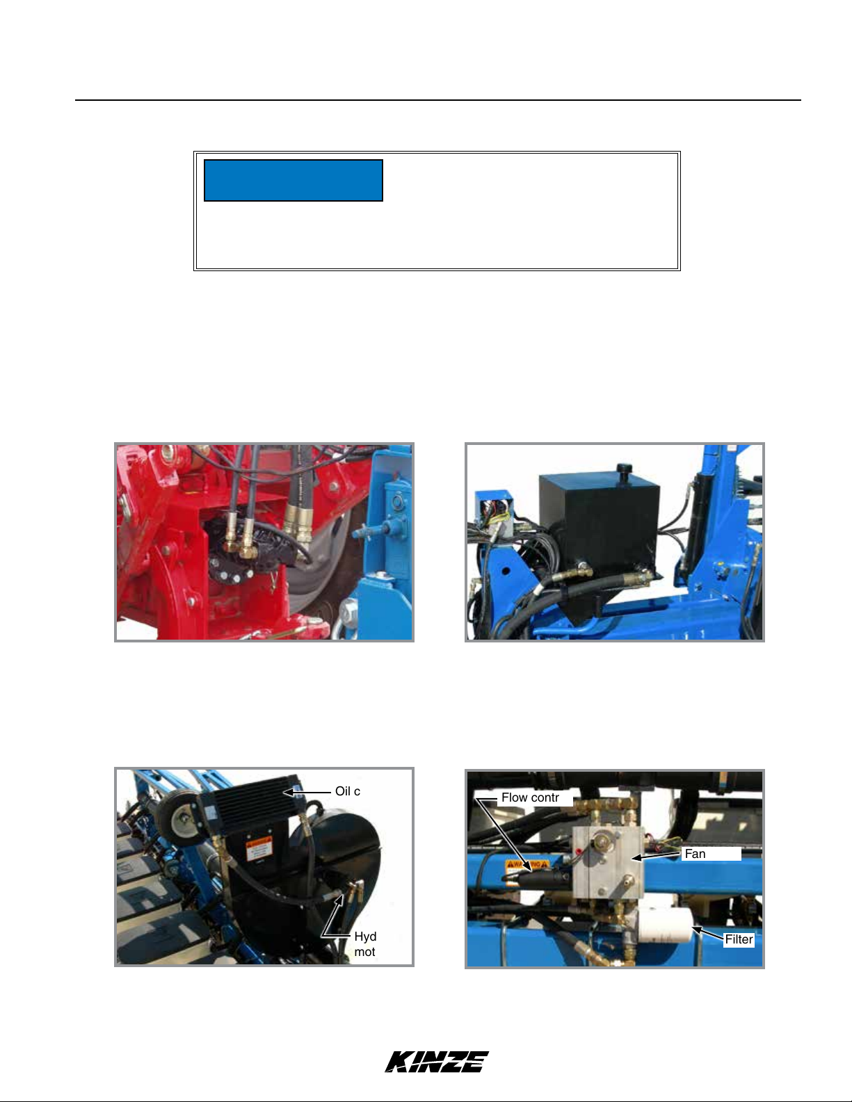
VACUUM TRACTOR MOUNTED PTO PUMP AND PLANTER MOUNTED HYDRAULICS
Two-section PTO hydraulic pump
Vacuum equipped planters require a 1¾" (45 mm)-20 spline 1000 RPM PTO to operate PTO-driven two section
hydraulic pump capable of supplying 57 L/min to two hydraulic motors/vacuum fans.
Vacuum Seed Metering System operates from an 30 L capacity oil reservoir.
Oil cooler
Hydraulic
motor
Vacuum fan assembly with oil cooler
Other dual fan system components include two oil coolers, two replaceable cartridge-type filters, two motorized flow
controls, pressure compensating valves, solenoid valves, and relief valves.
Flow control
8 gal (30 L) reservoir
Fan block
Filter
Vacuum fan block and filter
Rev. 10/18 2-5
TM
Page 24
Machine Operation
TRACTOR PREPARATION AND HOOKUP
M0275-01Model 3700
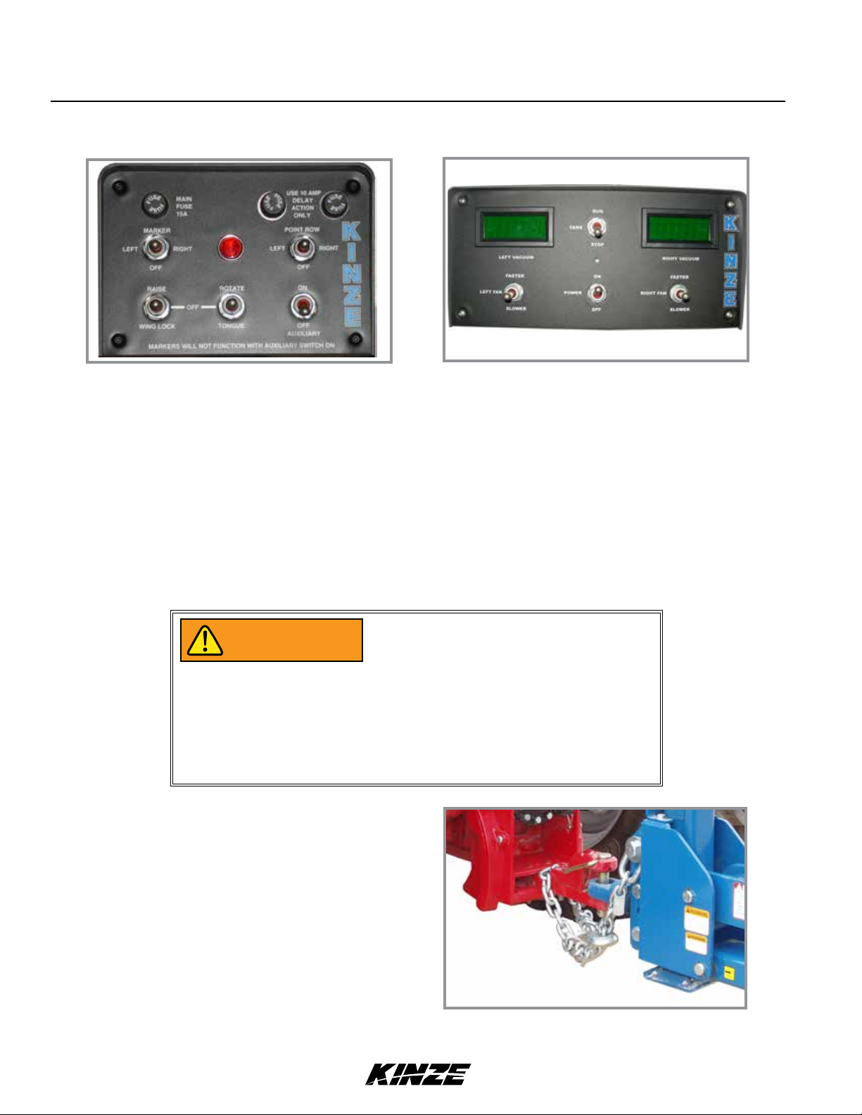
Planter control console
1. Install planter control console (all) and digital vacuum gauge (vacuum only) control consoles on tractor in
convenient locations within operator reach and close to hydraulic controls. Mount control consoles securely and
route power cables to power source. A power lead adapter may be required. See Lubrication and Maintenance
section for wiring schematics.
NOTE: Control console operates on 12 VDC only. If two 6 volt batteries are connected in series, make sure
power connection provides 12 VDC across positive terminal on one battery and negative terminal of second
battery. ALWAYS make power connection on battery grounded to tractor chassis.
2. Adjust tractor drawbar 33 cm - 43 cm above ground with hitch pin hole directly below PTO shaft center line. Make
sure drawbar is in a stationary position.
Planter hitch may raise uncontrollably
WARNING
during folding/unfolding and can cause
death, serious injury, or damage property
and equipment. DO NOT fold or unfold
planter without planter attached to a
tractor. DO NOT unhitch planter from
tractor unless fully folded for transport
or fully unfolded with planting units
lowered to ground.
Digital vacuum gauge control console
3. Back tractor to planter and connect with minimum
1¼" diameter hitch pin. Make sure hitch pin is
secured with a locking pin or cotter pin If tractor is
not equipped with a hitch pin locking device.
NOTE: DO NOT install safety chain using clevis
mounting hardware. Safety chain MUST be
installed separately.
4. Safety chain must be used to keep planter and
tractor connected in case of a hitch pin/drawbar
failure. Attach safety chain at an unused clevis
mounting hole on the planter hitch. Torque
hardware to 1140 Nm.
2-6 Rev. 10/18
Tractor and safety chain hookup
TM
Page 25
WARNING
NOTICE
Machine Operation
Model 3700M0275-01
Pressurized hydraulic fluid can penetrate
body tissue and result in death, serious
infection, or other injuries. Fluid injected
under skin must be IMMEDIATELY
removed by a surgeon familiar with this
type of injury. Make sure connections
are tight and hoses and fittings are
not damaged before applying system
pressure. Leaks can be invisible. Keep
away from suspected leaks. Relieve
pressure before searching for leaks or
performing any system maintenance.
Wipe hose ends to remove any dirt
before connecting couplers to tractor
parts or contamination may cause
equipment failure.
5. Connect hydraulic hoses to tractor ports in a sequence familiar and comfortable to the operator.
Connect hydraulic motor case drain to
NOTICE
NOTICE
a case drain return line with zero PSI
on tractor. Failure to connect to a return
with zero PSI will cause hydraulic motor
shaft seal damage. DO NOT connect
hydraulic motor case drain to a SCV
outlet or motor return circuit connection.
Contact tractor manufacturer for specific
details on “zero pressure return”.
Always connect hydraulic motor return
hose to tractor motor return port. Do not
connect to tractor SCV unless through
a motor spool or hydraulic motor failure
can occur. If a motor return port is
not available on the tractor, the SCV
controlling the bulk fill system MUST
be in the float position before planter is
moved in planting or field raised position
when bulk fill system is not in use.
Rev. 10/18 2-7
TM
Page 26
Machine Operation
Color and Label Machine Function Hose Size Hose Function
Red AA Field Lift ½" Pressure
Red BB ½" Return
Blue AA Planter Fold & Row Marker " Return
Blue BB " Pressure
Green RR Vacuum Fan ¾" Return
Green PP ½" Pressure
Orange CD
Yellow RR Bulk Fill System Pressure Fan ¾" Return
Yellow PP ½" Pressure
Orange CD
Clean and grease PTO shaft coupling
NOTICE
with high-pressure industrial coupling
grease (Chevron® coupling grease or
equivalent) meeting AGMA CG-1 and
CG-2 Standards each time driveshaft
is installed or premature wear and
equipment failure can occur.
" Case Drain
" Case Drain
M0275-01Model 3700
NOTE: A tractor model-specific PTO mount kit is required and available from Ag Power Systems, LLC
(319-646-2770 or agpowersystems.com) and Rowe Manufacturing (800-544-4123 or rowemfg.com).
6. (If applicable) Install PTO pump onto tractor PTO shaft. Make sure shaft rotation matches direction indicated on
pump housing.
7. Connect ASABE Standards 7 terminal connector for safety/warning lights on planter to ASABE Standards
receptacle on tractor. If your tractor is not equipped with an ASABE Standards receptacle, check with your tractor
manufacturer for availability. Check warning lights on planter work in conjunction with warning lights on tractor.
NOTE: A 12V battery connection is required to power the vacuum fan digital gauge. Connect “red” wire to
positive (+) battery terminal and “black” wire to negative (-) battery terminal.
Completely raise parking jack to prevent damage to jack assembly and equipment when moving planter.
2-8 Rev. 10/18
TM
Page 27
TRANSPORTING PLANTER
WARNING
WARNING
Machine Operation
Model 3700M0275-01
Loss of control of equipment during
transport can result in death, serious
injury, or damage to property and
equipment. Tractor gross weight must be
greater than planter gross weight with
attachments and options.
Uncontrolled movement of equipment
can cause loss of control and could
result in death, serious injury, or damage
to property and equipment. Install
all safety pins before transporting
equipment.
Uncontrolled machine movement can
WARNING
WARNING
Make sure safety/warning lights, reflective decals, and SMV sign are in place and visible before transporting machine
on public roads. It is your responsibility to check and comply with all federal, state/provincial, and local regulations.
Be aware of road and bridge weight limits. Allow for additional weight of added options and any additional material or
substances that have been added to the machine.
crush or cause loss of control resulting
in death, serious injury, or damage to
property and equipment. Install all safety
lockup devices before working under or
transporting this equipment.
Transporting planter with hoppers over
half full or unevenly loaded can cause
loss of control and could result in death,
serious injury, or damage to property and
equipment. Properly load planter when
transporting. Be aware of extra transport
weight, and road conditions and limits.
Rev. 10/18 2-9
TM
Page 28

Machine Operation
M0275-01Model 3700
CYLINDER INFORMATION
Master
Cylinder
Intended Use
Piston Ductile Iron Ductile Iron Ductile Iron Ductile Iron Ductile Iron Ductile Iron Ductile Iron Ductile Iron
End Mounts Tang Tang Tang Tang Sleeve Trunnion Sleeve Sleeve
Tube Seal
Rod Seal
Rod Wiper
Piston Seal PTFE Seal PTFE Seal PTFE Seal PTFE Seal T-Seal T-Seal PTFE Seal PTFE Seal
Product
Category
Maximum
Stroke
Double Acting
Applications
Gland Ductile Iron Ductile Iron Ductile Iron Ductile Iron Ductile Iron Ductile Iron Ductile Iron Ductile Iron
ST 52 DOM
Tube
Rod
Tubing
1045 Nitro
Rod
Buna O-Ring
with Polytemp
Back-up
Polyester Al-
loy U-cup
Polyester
Alloy
Snap In
Hydraulic
Cylinder
10"
(254 mm)
Slave Cylinder
Double Acting
Applications
ST 52 DOM
Buna O-Ring
with Polytemp
Alloy U-cup
(508 mm)
Tubing
1045 Nitro
Rod
Back-up
Polyester
Polyester
Alloy
Snap In
Hydraulic
Cylinder
20"
Hitch Parallel
Cylinder
Double Acting
Applications
ST 52 DOM
Tubing
1045 Nitro
Rod
Buna O-Ring
with Polytemp
Back-up
Polyester
Alloy U-cup
Polyester
Alloy
Snap In
Hydraulic
Cylinder
20"
(508 mm)
Assist
Cylinder
Double Acting
Applications
ST 52 DOM
Tubing
1045 Nitro
Rod
Buna O-Ring
with Polytemp
Back-up
Polyester
Alloy U-cup
Polyester
Alloy
Snap In
Specifications
Hydraulic
Cylinder
10"
(254 mm)
Row Marker
Cylinder
Double Acting
Applications
ST 52 DOM
Tubing
1045 Nitro
Rod
Buna O-Ring
with Polytemp
Back-up
Polyester
Alloy U-cup
Polyester
Alloy
Snap In
Hydraulic
Cylinder
20"
(508 mm)
Helper
Cylinder
(R.H. side)
Double Acting
Applications
ST 52 DOM
Tubing
1045 Nitro
Rod
Buna O-Ring
with Polytemp
Back-up
Polyester
Alloy U-cup
Polyester
Alloy
Snap In
Hydraulic
Cylinder
13.265"
(336 mm)
Tongue
Cylinder
(24R 20/22")
Double Acting
Applications
ST 52
Pre-honed
1045
Chrome Rod
Buna O-Ring
with Polytemp
Back-up
Polyester
Alloy U-cup
Polyester
Alloy
Snap In
Hydraulic
Cylinder
132"
(335 cm)
Tongue
Cylinder
(24R 30/
36R 20)
Double Acting
Applications
ST 52
Pre-honed
1045
Chrome Rod
Buna O-Ring
with Polytemp
Back-up
Polyester
Alloy U-cup
Polyester
Alloy
Snap In
Hydraulic
Cylinder
162"
(157.4 cm)
Working
Pressure
Bore Size
Shaft
Diameter
Cylinder
Configuration
Cylinder
Action
Material
Mounting
Method
Mount
Location
Cylinder Style
3000 PSI
(20700 kPa)
4.5"
(114 mm)
2"
(51 mm)
3000 PSI
(20700 kPa)
4.75"
(120 mm)
2"
(51 mm)
3000 PSI
(20700 kPa)
3.5"
(88 mm)
2.5"
(63 mm)
3000 PSI
(20700 kPa)
3"
(76 mm)
1.75"
(44 mm)
3000 PSI
(20700 kPa)
3.5"
(88 mm)
1.5"
(38 mm)
3000 PSI
(20700 kPa)
4"
(101 mm)
1.5"
(38 mm)
3000 PSI
(20700 kPa)
4"
(101 mm)
2.5"
(63 mm)
3000 PSI
(20700 kPa)
(101 mm)
2.5"
(63 mm)
Simple Simple Simple Simple Simple Simple Simple Simple
Double Double Double Double Double Double Double Double
Steel,
Ductile Iron
Steel,
Ductile Iron
Steel,
Ductile Iron
Steel,
Ductile Iron
Steel,
Ductile Iron
Steel,
Ductile Iron
Steel,
Ductile Iron
Steel,
Ductile Iron
Tang Tang Tang Tang Sleeve Trunnion Sleeve Sleeve
End Cap End Cap End Cap End Cap End Cap End Cap End Cap End Cap
Welded Welded Welded Welded Welded Welded Welded Welded
4"
2-10 Rev. 10/18
TM
Page 29

Machine Operation
Model 3700M0275-01
HYDRAULIC HOSE INFORMATION
Part Number
Description
Product Cat-
egory
Product Form Hose; Assembly Hose; Assembly Hose; Assembly Hose; Assembly Hose; Assembly Hose; Assembly
I.D. ³⁄" (9.5 mm) ⁄" (12.7 mm) ⁄" (12.7 mm) ⁄" (12.7 mm) ³⁄" (9.5 mm) ³⁄" (9.5 mm)
O.D.
Minimum Bend
Radius
Working Pres-
sure
Temperature
Range
Material
Specialized
Construction
Media Hydraulic Fluid Hydraulic Fluid Hydraulic Fluid Hydraulic Fluid Hydraulic Fluid Hydraulic Fluid
Application
A1044 A1412 A1499 A1498 A1089 A3141
Hose Assembly,
³⁄" x 34" (0.86 m)
Hydraulic Hose Hydraulic Hose Hydraulic Hose Hydraulic Hose Hydraulic Hose Hydraulic Hose
/" (17.5 mm) /" (20.6 mm) /" (20.6 mm) /" (20.6 mm) /" (17.5 mm) /" (17.5 mm)
2½" (64 mm) 3½" (89 mm) 3½" (89 mm) 3½" (89 mm) 2½" (64 mm) 2½" (64 mm)
3000 PSI
(20700 kPa)
-40°C - +100°C -40°C - +100°C -40°C - +100°C -40°C - +100°C -40°C - +100°C -40°C - +100°C
Modified Nitrile
Type C2
High tensile
steel wire
Agricultural;
Construction
Hose Assembly,
⁄" x 130" (3.30 m)
3000 PSI
(20700 kPa)
Modified Nitrile
Type C2
High tensile
steel wire
Agricultural;
Construction
Hose Assembly,
⁄" x 280" (7.11 m)
3000 PSI
(20700 kPa)
Modified Nitrile
Type C2
High tensile
steel wire
Agricultural;
Construction
Hose Assembly,
⁄" x 452" (11.4 m)
3000 PSI
(20700 kPa)
Modified Nitrile
Type C2
High tensile
steel wire
Agricultural;
Construction
Hose Assembly,
³⁄" x 240" (6.09 m)
3000 PSI
(20700 kPa)
Modified Nitrile
Type C2
High tensile
steel wire
Agricultural;
Construction
Hose Assembly,
³⁄" x 260" (6.60 m)
3000 PSI
(20700 kPa)
Modified Nitrile
Type C2
High tensile
steel wire
Agricultural;
Construction
Part Number
Description
Product Cat-
egory
Product Form Hose; Assembly Hose; Assembly Hose; Assembly Hose; Assembly Hose; Assembly Hose; Assembly
I.D. ⁄" (12.7 mm) ³⁄" (9.5 mm) ³⁄" (9.5 mm) ½" (12.7 mm) ³⁄" (9.5 mm) ³⁄" (9.5 mm)
O.D.
Minimum Bend
Radius
Working Pres-
sure
Temperature
Range
Material
Specialized
Construction
Media Hydraulic Fluid Hydraulic Fluid Hydraulic Fluid Hydraulic Fluid Hydraulic Fluid Hydraulic Fluid
Application
A1487 A3196 A3212 A1404 A1072 A1049
Hose Assembly,
⁄" x 150" (3.8 m)
Hydraulic Hose Hydraulic Hose Hydraulic Hose Hydraulic Hose Hydraulic Hose Hydraulic Hose
/" (20.6 mm) /" (17.5 mm) /" (17.5 mm) /" (20.6 mm) /" (17.5 mm) /" (17.5 mm)
3½" (89 mm) 2½" (64 mm) 2½" (64 mm) 3½" (89 mm) 2½" (64 mm) 2½" (51 mm)
3000 PSI
(20700 kPa)
-40°C - +100°C -40°C - +100°C -40°C - +100°C -40°C - +100°C -40°C - +100°C -40°C - +100°C
Modified Nitrile
Type C2
High tensile
steel wire
Agricultural;
Construction
Hose Assembly,
³⁄" x 240" (6.09 m)
3000 PSI
(20700 kPa)
Modified Nitrile
Type C2
High tensile
steel wire
Agricultural;
Construction
Hose Assembly,
³⁄" x 260" (6.60 m)
3000 PSI
(20700 kPa)
Modified Nitrile
Type C2
High tensile
steel wire
Agricultural;
Construction
Hose Assembly,
½" x 41" (1.0 m)
(10F - 10F)
3000 PSI
(20700 kPa)
Modified Nitrile
Type C2
Single Wire
Braid
Agricultural;
Construction
Hose Assembly,
³⁄" x 48" (1.21 m)
3250 PSI
(22400 kPa)
Modified Nitrile
Type C2
High tensile
steel wire
Agricultural;
Construction
Hose Assembly,
³⁄" x 160" (4.06 m)
3000 PSI
(20700 kPa)
Modified Nitrile
Type C2
High tensile
steel wire
Agricultural;
Construction
Rev. 10/18 2-11
TM
Page 30

Machine Operation
M0275-01Model 3700
HYDRAULIC HOSE INFORMATION
Part Number
Description
Product Cat-
egory
Product Form Hose; Assembly Hose; Assembly Hose; Assembly Hose; Assembly Hose; Assembly Hose; Assembly
I.D. ³⁄" (9.5 mm) ³⁄" (9.5 mm) ³⁄" (9.5 mm) ³⁄" (9.5 mm) ³⁄" (9.5 mm) ³⁄" (9.5 mm)
O.D.
Minimum Bend
Radius
Working
Pressure
Temperature
Range
Material
Specialized
Construction
Media Hydraulic Fluid Hydraulic Fluid Hydraulic Fluid Hydraulic Fluid Hydraulic Fluid Hydraulic Fluid
Application
A3175 A1020 A1010 A3271 A3272 A3119
Hose Assembly,
³⁄" x 38" (0.97 m)
Hydraulic Hose Hydraulic Hose Hydraulic Hose Hydraulic Hose Hydraulic Hose Hydraulic Hose
/" (17.5 mm) /" (17.5 mm) /" (17.5 mm) /" (17.5 mm) /" (17.5 mm) /" (17.5 mm)
2½" (64 mm) 2½" (64 mm) 2½" (64 mm) 2½" (64 mm) 2½" (64 mm) 2½" (64 mm)
3000 PSI
(20700 kPa)
-40°C - +100°C -40°C - +100°C -40°C - +100°C -40°C - +100°C -40°C - +100°C -40°C - +100°C
Modified Nitrile
Type C2
High tensile
steel wire
Agricultural;
Construction
Hose Assembly,
³⁄" x 38" (0.97 m)
3000 PSI
(20700 kPa)
Modified Nitrile
Type C2
High tensile
steel wire
Agricultural;
Construction
Hose Assembly,
³⁄" x 120" (3.05 m)
3000 PSI
(20700 kPa)
Modified Nitrile
Type C2
High tensile
steel wire
Agricultural;
Construction
Hose Assembly,
³⁄" x 402" (10.21 m)
3000 PSI
(20700 kPa)
Modified Nitrile
Type C2
High tensile
steel wire
Agricultural;
Construction
Hose Assembly,
³⁄" x 426" (10.82 m)
3000 PSI
(20700 kPa)
Modified Nitrile
Type C2
High tensile
steel wire
Agricultural;
Construction
Hose Assembly,
³/" x 36" (0.91 m)
3000 PSI
(20700 kPa)
Modified Nitrile
Type C2
High tensile
steel wire
Agricultural;
Construction
Part Number
Description
Product
Category
Product Form Hose; Assembly Hose; Assembly Hose; Assembly Hose; Assembly Hose; Assembly Hose; Assembly
I.D. /" (12.7 mm) ³/" (9.5 mm) ³/" (9.5 mm) ¼" (6.4 mm) ¼" (6.4 mm) ³/" (9.5 mm)
O.D.
Minimum Bend
Radius
Working
Pressure
Temperature
Range
Material
Specialized
Construction
Media Hydraulic Fluid Hydraulic Fluid Hydraulic Fluid Hydraulic Fluid Hydraulic Fluid Hydraulic Fluid
Application
A1475 A1057 A1019 A1146 A1189 A12026
Hose Assembly,
/" x 108" (2.74 m)
Hydraulic Hose Hydraulic Hose Hydraulic Hose Hydraulic Hose Hydraulic Hose Hydraulic Hose
/" (20.6 mm) /" (17.5 mm) /" (17.5 mm) /" (13.5 mm) /" (13.5 mm) /" (17.5 mm)
3½" (89 mm) 2½" (64 mm) 2½" (64 mm) 4" (102 mm) 4" (102 mm) 2½" (64 mm)
3000 PSI
(20700 kPa)
-40°C - +100°C -40°C - +100°C -40°C - +100°C -40°C - +100°C -40°C - +100°C -40°C - +100°C
Modified Nitrile
Type C2
High tensile
steel wire
Agricultural;
Construction
Hose Assembly,
³⁄" x 216" (5.48 m)
3000 PSI
(20700 kPa)
Modified Nitrile
Type C2
High tensile
steel wire
Agricultural;
Construction
Hose Assembly,
³⁄" x 44" (1.11 m)
3000 PSI
(20700 kPa)
Modified Nitrile
Type C2
High tensile
steel wire
Agricultural;
Construction
Hose Assembly,
¼" x 12" (0.30 m)
3275 PSI
(22600 kPa)
Modified Nitrile
Type C2
High tensile
steel wire
Agricultural;
Construction
Hose Assembly,
¼" x 36" (0.91 m)
3275 PSI
(22600 kPa)
Modified Nitrile
Type C2
High tensile
steel wire
Agricultural;
Construction
Hose Assembly,
³⁄" x 148" (3.76 m)
3000 PSI
(20700 kPa)
Modified Nitrile
Type C2
High tensile
steel wire
Agricultural;
Construction
2-12 Rev. 10/18
TM
Page 31

Machine Operation
Model 3700M0275-01
HYDRAULIC HOSE INFORMATION
Part Number
Description
Product
Category
Product Form Hose; Assembly Hose; Assembly Hose; Assembly Hose; Assembly Hose; Assembly Hose; Assembly
I.D. ½" (12.7 mm) " (9.5 mm) " (9.5 mm) " (9.5 mm) " (9.5 mm) " (9.5 mm)
O.D.
Minimum Bend
Radius
Working
Pressure
Temperature
Range
Material
Specialized
Construction
Media Hydraulic Fluid Hydraulic Fluid Hydraulic Fluid Hydraulic Fluid Hydraulic Fluid Hydraulic Fluid
Application
A1424 A1025 A3105 A1013 A15022 A1073
Hose Assembly
½" x 30" (0.76 m)
Hydraulic Hose Hydraulic Hose Hydraulic Hose Hydraulic Hose Hydraulic Hose Hydraulic Hose
/" (20.6 mm) /" (17.5 mm) /" (17.5 mm) /" (17.5 mm) /" (17.5 mm) /" (17.5 mm)
3½" (89 mm) 2½" (64 mm) 2½" (64 mm) 2½" (64 mm) 2½" (64 mm) 2½" (64 mm)
3000 PSI
(20700 kPa)
-40°C - +100°C -40°C - +100°C -40°C - +100°C -40°C - +100°C -40°C - +100°C -40°C - +100°C
Modified Nitrile
Type C2
Single Wire
Braid
Agricultural and
Construction
Hose Assembly
" x 148" (3.76 m)
3000 PSI
(20700 kPa)
Modified Nitrile
Type C2
Single Wire
Braid
Agricultural;
Construction
Hose Assembly
" x 170" (4.32 m)
3000 PSI
(20700 kPa)
Modified Nitrile
Type C2
Single Wire
Braid
Agricultural;
Construction
Hose Assembly
" x 150" (3.81 m)
3000 PSI
(20700 kPa)
Modified Nitrile
Type C2
Single Wire
Braid
Agricultural;
Construction
Hose Assembly
" x 438" (11.13 m)
3000 PSI
(20700 kPa)
Modified Nitrile
Type C2
Single Wire
Braid
Agricultural;
Construction
Hose Assembly
" x 18" (0.46 m)
3000 PSI
(20700 kPa)
Modified Nitrile
Type C2
Single Wire
Braid
Agricultural;
Construction
Part Number
Description
Product
Category
Product Form Hose; Assembly Hose; Assembly Hose; Assembly Hose; Assembly Hose; Assembly Hose; Assembly
I.D. /" (9.5 mm) " (9.5 mm) " (9.5 mm) " (9.5 mm) " (9.5 mm) " (9.5 mm)
O.D.
Minimum Bend
Radius
Working
Pressure
Temperature
Range
Material
Specialized
Construction
Media Hydraulic Fluid Hydraulic Fluid Hydraulic Fluid Hydraulic Fluid Hydraulic Fluid Hydraulic Fluid
Application
A8500 A3140 A3111 A1026 A1031 A3161
Hose Assembly
" x 260" (6.60 m)
Hydraulic Hose Hydraulic Hose Hydraulic Hose Hydraulic Hose Hydraulic Hose Hydraulic Hose
.42" (11.0 mm) /" (17.5 mm) /" (17.5 mm) /" (17.5 mm) /" (17.5 mm) /" (17.5 mm)
¾" (19.0 mm) 2½" (64 mm) 2½" (64 mm) 2½" (64 mm) 2½" (64 mm) 2½" (64 mm)
3500 PSI
(24100 kPa)
-40°C - +100°C -40°C - +100°C -40°C - +100°C -40°C - +100°C -40°C - +100°C -40°C - +100°C
Modified Nitrile
Type C2
Single Wire
Braid
Agricultural;
Construction
Hose Assembly
" x 94" (2.39 m)
3000 PSI
(20700 kPa)
Modified Nitrile
Type C2
Single Wire
Braid
Agricultural;
Construction
Hose Assembly
" x 200" (5.08 m)
(08F - 08F)
3000 PSI
(20700 kPa)
Modified Nitrile
Type C2
Single Wire
Braid
Agricultural;
Construction
Hose Assembly
" x 152" (3.86 m)
3000 PSI
(20700 kPa)
Modified Nitrile
Type C2
Single Wire
Braid
Agricultural;
Construction
Hose Assembly
" x 234" (5.94 m)
3000 PSI
(20700 kPa)
Modified Nitrile
Type C2
Single Wire
Braid
Agricultural;
Construction
Hose Assembly
" x 210" (5.33 m)
3000 PSI
(20700 kPa)
Modified Nitrile
Type C2
Single Wire
Braid
Agricultural;
Construction
Rev. 10/18 2-13
TM
Page 32

Machine Operation
M0275-01Model 3700
HYDRAULIC HOSE INFORMATION
Part Number
Description
Product
Category
Product Form Hose; Assembly Hose; Assembly Hose; Assembly Hose; Assembly Hose; Assembly Hose; Assembly
I.D. " (9.5 mm) /" (12.7 mm) ³/" (9.5 mm) /" (12.7 mm) /" (12.7 mm) /" (12.7 mm)
O.D.
Minimum Bend
Radius
Working
Pressure
Temperature
Range
Material
Specialized
Construction
Media Hydraulic Fluid Hydraulic Fluid Hydraulic Fluid Hydraulic Fluid Hydraulic Fluid Hydraulic Fluid
Application
A3299 A8201 A12000 A1485 A8208 A8273
Hose Assembly
" x 164" (4.17 m)
Hydraulic Hose Hydraulic Hose Hydraulic Hose Hydraulic Hose Hydraulic Hose Hydraulic Hose
/" (16.0 mm) /" (20.6 mm) /" (16.0 mm) /" (20.6 mm) /" (20.6 mm) /" (20.6 mm)
2½" (64 mm) 3½" (89 mm) 2½" (64 mm) 3½" (89 mm) 3½" (89 mm) 3½" (89 mm)
3000 PSI
(20700 kPa)
-40°C - +100°C -40°C - +100°C -40°C - +100°C -40°C - +100°C -40°C - +100°C -40°C - +100°C
Modified Nitrile
Type C2
Single Wire
Braid
Agricultural;
Construction
Hose Assembly,
⁄" x 90" (2.29 m)
3000 PSI
(20700 kPa)
Modified Nitrile
Type C2
High tensile
steel wire
Agricultural;
Construction
Hose Assembly,
³⁄" x 548" (13.92 m)
3000 PSI
(20700 kPa)
Modified Nitrile
Type C2
High tensile
steel wire
Agricultural;
Construction
Hose Assembly,
/" x 330" (8.38 m)
3000 PSI
(20700 kPa)
Modified Nitrile
Type C2
High tensile
steel wire
Agricultural;
Construction
Hose Assembly,
/" x 374" (9.51 m)
3250 PSI
(22400 kPa)
Modified Nitrile
Type C2
High tensile
steel wire
Agricultural;
Construction
Hose Assembly,
/" x 21" (0.53 m)
3000 PSI
(20700 kPa)
Modified Nitrile
Type C2
High tensile
steel wire
Agricultural;
Construction
Part Number
Description
Product
Category
Product Form Hose; Assembly Hose; Assembly Hose; Assembly Hose; Assembly Hose; Assembly Hose; Assembly
I.D. /" (12.7 mm) /" (12.7 mm) /" (4.7 mm) /" (4.7 mm) ³/" (9.5 mm) ³/" (9.5 mm)
O.D.
Minimum Bend
Radius
Working
Pressure
Temperature
Range
Material
Specialized
Construction
Media Hydraulic Fluid Hydraulic Fluid Hydraulic Fluid Hydraulic Fluid Hydraulic Fluid Hydraulic Fluid
Application
A12749 A1465 A8501 A8503 A12082 A1038
Hose Assembly,
/" x 198" (5.03 m)
Hydraulic Hose Hydraulic Hose Hydraulic Hose Hydraulic Hose Hydraulic Hose Hydraulic Hose
/" (20.6 mm) /" (20.6 mm) .42" (10.2 mm) .42" (10.2 mm) /" (17.5 mm) /" (17.5 mm)
3½" (89 mm) 3½" (89 mm) ¾" (19 mm) ¾" (19 mm) 2½" (64 mm) 2½" (64 mm)
3000 PSI
(20700 kPa)
-40°C - +100°C -40°C - +100°C -40°C - +100°C -40°C - +100°C -40°C - +100°C -40°C - +100°C
Modified Nitrile
Type C2
High tensile
steel wire
Agricultural;
Construction
Hose Assembly,
/" x 84" (2.13 m)
3000 PSI
(20700 kPa)
Modified Nitrile
Type C2
High tensile
steel wire
Agricultural;
Construction
Hose Assembly
³/" x 426" (10.82 m)
3500 PSI
(24100 kPa)
Modified Nitrile
Type C2
Single Wire
Braid
Agricultural;
Construction
Hose Assembly
³/" x 436" (11.07 m)
3500 PSI
(24100 kPa)
Modified Nitrile
Type C2
Single Wire
Braid
Agricultural;
Construction
Hose Assembly,
³⁄" x 418" (10.62 m)
3000 PSI
(20700 kPa)
Modified Nitrile
Type C2
High tensile
steel wire
Agricultural;
Construction
Hose Assembly,
³⁄" x 370" (9.41 m)
3000 PSI
(20700 kPa)
Modified Nitrile
Type C2
High tensile
steel wire
Agricultural;
Construction
2-14 Rev. 10/18
TM
Page 33

Machine Operation
Model 3700M0275-01
HYDRAULIC HOSE INFORMATION
Part Number
Description
Product
Category
Product Form Hose; Assembly Hose; Assembly Hose; Assembly Hose; Assembly Hose; Assembly Hose; Assembly
I.D. /" (12.7 mm) " (9.5 mm) " (9.5 mm) /" (4.7 mm) ³/" (9.5 mm) ³/" (9.5 mm)
O.D.
Minimum Bend
Radius
Working
Pressure
Temperature
Range
Material
Specialized
Construction
Media Hydraulic Fluid Hydraulic Fluid Hydraulic Fluid Hydraulic Fluid Hydraulic Fluid Hydraulic Fluid
Application
A8283 A3122 A12083 A8502 A3178 A1098
Hose Assembly,
/" x 158" (4.01 m)
Hydraulic Hose Hydraulic Hose Hydraulic Hose Hydraulic Hose Hydraulic Hose Hydraulic Hose
/" (20.6 mm) /" (17.5 mm) /" (17.5 mm) .42" (10.2 mm) /" (17.5 mm) /" (17.5 mm)
3½" (89 mm) 2½" (64 mm) 2½" (64 mm) ¾" (7.6 cm) 2½" (64 mm) 2½" (51 mm)
3000 PSI
(20700 kPa)
-40°C - +100°C -40°C - +100°C -40°C - +100°C -40°C - +100°C -40°C - +100°C -40°C - +100°C
Modified Nitrile
Type C2
High tensile
steel wire
Agricultural;
Construction
Hose Assembly "
x 10.5" (0.31 m)
3000 PSI
(20700 kPa)
Modified Nitrile
Type C2
Single Wire
Braid
Agricultural;
Construction
Hose Assembly
" x 436" (11.10 m)
3000 PSI
(20700 kPa)
Modified Nitrile
Type C2
Single Wire
Braid
Agricultural;
Construction
Hose Assembly
³/" x 270" (6.91 m)
3500 PSI
(24100 kPa)
Modified Nitrile
Type C2
Single Wire
Braid
Agricultural;
Construction
Hose Assembly, ³⁄"
x 536" (13.61 m)
3000 PSI
(20700 kPa)
Modified Nitrile
Type C2
High tensile
steel wire
Agricultural;
Construction
Hose Assembly,
³⁄" x 26" (0.66 m)
3000 PSI
(20700 kPa)
Modified Nitrile
Type C2
High tensile
steel wire
Agricultural;
Construction
Rev. 10/18 2-15
TM
Page 34

LEVEL PLANTER
Machine Operation
M0275-01Model 3700
Approximately
parallel with
planting surface
Clevis adjustment holes
Level row units
Toolbar should operate at 50 cm - 56 cm height from planting surface. Tire pressures must be maintained at pressures
specified for planter to operate level laterally. Check toolbar and row unit parallel arms are level front to back with
planter lowered to proper operating height.
Five holes in the hitch bracket allow clevis to be raised or lowered. Clevis may be turned over for a finer adjustment
between mounting holes. Torque hardware to 1138.8 Nm.
Field and actual planting conditions determine which wheel settings to use to ensure row unit parallel arms are
approximately parallel with planting surface. If planting in extremely soft soil conditions it may be necessary to move
ground drive tires to lower sets of mounting holes. To allow adequate drive force after lowering the ground drive tires,
it may be necessary to lower contact drive arms to lower set of holes in wheel module and relocate down pressure
springs to lower mounting rod on wheel module.
If planter center is higher or lower than wings after rephasing, contact your Kinze Dealer for valve adjustment or
maintenance.
CONTACT WHEEL SPRING ADJUSTMENT
20 cm (8")
Spring length measurement (Factory setting)
Contact drive springs
There are two down pressure springs on each contact drive wheel. Spring tension is factory set to approximately 90 kg
of down force at tire contact point and should require no further adjustment.
NOTE: Measurement must be taken in planting position with proper tire pressure.
2-16 Rev. 10/18
TM
Page 35

Machine Operation
Model 3700M0275-01
CONTACT WHEEL DRIVE SPROCKETS
Contact drive wheel sprocket
Sprocket idler
Contact wheel drive Optional half-rate drive sprocket
Contact wheel drive works the same for mechanical or vacuum planters except for sprocket size. Chain tension is
controlled by a spring-loaded sprocket idler. Planting rate charts in “Rate Chart” section help you select correct sprockets.
NOTE: Make a field test after each sprocket combination change to be sure you are planting at desired rate.
22 tooth, 28 tooth or 44 tooth sprockets at each contact drive wheel can be exchanged with sprockets on storage rod
bolted to wheel module on each side of planter chains. 22 tooth sprockets require 148 pitch No. 40 chains. 28 tooth
sprockets require 150 pitch chains. 44 tooth sprockets require use 158 pitch chains.
NOTE: 22, 28 and 44 tooth drive sprockets do NOT apply to all rate charts. Check chart titles to make sure proper
rate chart is selected.
NOTE: 54 cell sunflower disc uses 15 tooth drive sprocket at contact wheels and 28 tooth drive sprocket at wheel
module reverser plates with 19 tooth sprocket. 15 tooth sprockets require 144 pitch No. 40 chains. Applicable
sprockets, chains and instructions supplied in G1K469 Sunflower Rate Reduction Kit.
Seed planting rate charts are based on standard rate drive. Standard rate drive uses a 30 tooth sprocket and No. 40 118
pitch chain on each contact wheel. Optional half-rate (2 to 1) drive is recommended only when population falls below planting
rate charts. Replace 30 tooth sprocket on each contact wheel with a 15 tooth sprocket and shorter No. 40 110 pitch chain.
This reduces planter transmission speed and planting and application rates by approximately 50%.
SEED RATE TRANSMISSION ADJUSTMENT
Planting population rate changes are made using seed
rate transmissions at end of each planter wing. Seed
rate transmissions allow simple, rapid changes of
sprockets by removing lynch pins on hexagon shafts
and changing sprockets with those from the sprocket
storage rod bolted to transmissions.
Drive
Chain tension is controlled by a spring-loaded dual
sprocket idler. Idler assembly is adjusted with a easyrelease idler arm with a release position to adjust
spring tension for planting or remove spring tension
Driven
for replacing sprockets. See ‘‘Wrap Spring Wrench
Operation’’.
Seed rate transmission
A decal on the transmission (behind chain idler) shows proper chain routing. “Rate Charts” section of this manual will
help you select correct sprocket combinations.
Rev. 10/18 2-17
TM
Page 36

Machine Operation
M0275-01Model 3700
WRAP SPRING WRENCH OPERATION
Chain idlers are equipped with wrap spring wrenches. L.H. rotation wrap spring wrenches have a blue release collar and
R.H. rotation wrap spring wrenches have a grey or black release collar.
Collar
Wrap spring wrench (L.H. rotation shown)
Rotate collar on wrap spring wrench and pull handle to release chain tension.
Rotate chain idler into chain and pull handle to tension idler spring.
SHEAR PROTECTION
Transmission shaft shear pin
Spare shear pin storage
Chain idler tensioning
Planter driveline and seed and granular chemical drivelines are protected from damage by shear pins.
Misalignment of drill shaft/transmission
NOTICE
Determine where binding has occurred if excessive load causes a pin to shear before replacing pin. Replace shear
pins with same size and type.
Additional shear pins are in the storage area located at end of each planter wing on inboard side of transport hook.
2-18 Rev. 10/18
coupler alignment will cause equipment
damage.
TM
Page 37

Machine Operation
Model 3700M0275-01
SLIDING HITCH LINKAGE
Axle link
Draft link
Axle link slide (L.H. shown)
24 Row 70 cm planters are equipped with sliding axle links which connect R.H. and L.H. draft links to transport axle.
Axle links move in a slide on inner side of each draft link when planter folds or unfolds. When axle links reach end of
slides, main transport axle is telescoped forward into transport position or rearward into field position.
DO NOT GREASE axle link slides or
NOTICE
excess dirt accumulation may cause
equipment failure. Inspect daily to ensure
free movement of axle links in slides. Keep
axle link slides clean. Use only powdered
graphite if lubrication is desired.
Stops at either end of slides are designed to allow dirt to escape In normal operating conditions. Under extremely
dusty conditions it may be necessary to clean slides.
DIGITAL VACUUM GAUGE
Digital vacuum gauge control console is equipped with a
power toggle switch, run/stop (fans) toggle switch, and two
fan speed control toggle switches for the vacuum fans.
Power switch applies power to control console. Run/stop
toggle switch turns both fans on when power switch is ON.
Fan speed control switches adjusts each fan (left or right).
Digital vacuum gauge control console
PTO PUMP INITIAL STARTUP
1. Fill reservoir with SAE 10W-20 multigrade wide temperature range transmission hydraulic fluid or equivalent.
2. Start system. Allow to run with tractor at idle and fans turned off for 1-2 minutes.
3. Allow to run with tractor at idle and fans at full speed for 1-2 minutes.
4. Check fluid level in reservoir and fill as required.
NOTE: Fluid level in each tank should be within 1.5 cm - 5 cm from top of the tank after pump has run and
hydraulic hoses are primed to allow fluid to expand when heated.
5.
Bring tractor to PTO speed and adjust flow control to desired vacuum level using switches on vacuum fan control console.
Rev. 10/18 2-19
TM
Page 38

Machine Operation
M0275-01Model 3700
HYDRAULIC/ELECTRIC OPERATION
Control console switches and tractor’s hydraulic system are used to raise planter to transport position, operate rotate
and tongue extension functions, lock and release planter wings, and raise and lower row markers.
NOTE: Turn console backlighting OFF during extended periods of non-use using push button switch on back
of console.
Single point row clutch control box
Two dual remote hydraulic outlets (SCV) are required on all sizes of conventional planters equipped with row
markers. Three dual remote hydraulic outlets (SCV) are required on all sizes of bulk fill planters equipped with row
markers. One set of outlets is used to operate lift function, one set is used to operate markers, tongue and fold/unfold
functions and the third set is used to operate bulk fill functions (If Applicable).
Marker and point row selector switches are an ON-OFF-ON type. If planter is equipped with optional Two-Speed Point
Row Clutch Package, point row switch and reduced rate switch operate independently from rest of control console.
Power to marker switch is fed through auxiliary switch and two transport function switches. Operating any lower row
switch disables markers and turns off marker indicator light.
Raise/wing lock and rotate/tongue (fold function) switches are MOMENTARY ON-OFF-MOMENTARY ON type and must
be held in position while operating tractor hydraulic SCV control. Activating a fold function switch disables marker circuit.
Marker selector switch must be OFF
WARNING
(center position) when not in use to
prevent accidental extension which
could result in death or serious injury, or
damage to property and equipment. An
indicator light on control box panel is ON
whenever marker circuits or point row
clutch circuits are energized.
Two-speed point row clutch control box
Auxiliary switch is not used. Keep switch OFF at all times.
NOTE: Activating auxiliary switch disables all other control console switches except point row clutch switch.
2-20 Rev. 10/18
TM
Page 39

Machine Operation
TRANSPORT TO FIELD SEQUENCE
Position planter in a relatively flat open area without furrows, etc.
SUMMARIZED TRANSPORT TO FIELD SEQUENCE
1. Remove hitch parallel linkage lock pin or lockup.
2. Lower hitch parallel linkage to release wing hooks.
Unfolding planter without using tractor
NOTICE
3. Place tractor in reverse and hold in clutch. Start unfolding planter and slowly
back up tractor as planter unfolds.
4. Raise planter to remove weight from center (slave) lift cylinder lockups and
remove lockups.
5. Lower planter.
6. Remove row marker lockups.
to assist may cause equipment damage
especially in soft conditions or when
loaded with seed or fertilizer. Use tractor
to reduce stress on frame, drive, and
transport components.
Model 3700M0275-01
NOTE: Read following information for detailed instructions.
Rev. 10/18 2-21
TM
Page 40

WARNING
NOTICE
Machine Operation
M0275-01Model 3700
Planter hitch may raise uncontrollably
during folding/unfolding and can cause
death, serious injury, or damage property
and equipment. DO NOT fold or unfold
planter without planter attached to a
tractor. DO NOT unhitch planter from
tractor unless fully folded for transport
or fully unfolded with planting units
lowered to ground.
DO NOT LOWER planter frame onto
transport axle in folded transport position
or transport tires and row units will be
damaged.
Hitch parallel linkage pin storedHitch parallel linkage pin installed
1. Fully extend hitch parallel linkage cylinder located on hitch. Remove hitch parallel linkage lock pin from hitch
parallel linkage or cylinder lockup from cylinder rod. Store in location provided.
2-22 Rev. 10/18
TM
Page 41

Machine Operation
Model 3700M0275-01
Hitch release from wing hook
2. Hold “ROTATE/TONGUE” switch in “TONGUE” position while operating proper tractor hydraulic control to
completely retract hitch parallel linkage cylinder and lower hitch until wing wheels are on ground and hitch has
released from hooks on ends of wings.
Planter unfolding
Unfolding planter without using tractor
NOTICE
3. Hold control console ROTATE/TONGUE switch in ROTAT E and operate hydraulic control to unfold planter. Tongue
begins to retract and wings (supported by wing wheels) begin to unfold. Place tractor transmission in a low reverse
gear and slowly back up as planter unfolds. Center axle tires should remain stationary and wing tires should roll in
a continuous arc with minimal side loading on tires or their mounting structures. Hold switch in “ROTATE” position
until tongue cylinder is fully retracted.
Rev. 10/18 2-23
to assist may cause equipment damage
especially in soft conditions or when
loaded with seed or fertilizer. Use tractor
to reduce stress on frame, drive, and
transport components.
TM
Page 42

Machine Operation
M0275-01Model 3700
Safety lockups in transport position
Safety lockups in storage position
NOTE: Automatic safety lock will release when planter is raised to remove weight from center lift cylinder
lockups. Raising planter too high will reset the mechanism. If this happens, lower machine until hydraulic
system stalls against the automatic safety, raise machine slightly to release automatic safety lock
and then lower planter.
4. Raise planter to remove weight from center lift (slave) cylinder safety lockups. Remove pins and safety lockups
and place in storage location.
Lower machine to ground. Center drops until toolbar
5.
is level and then entire planter lowers evenly. Hold
tractor’s hydraulic lever 5 to 10 seconds to rephase
system when all lift cylinders are fully retracted.
Lowering planter
Row marker safety lockup installed
Row marker safety lockup stored
6. Remove and store marker lockups.
2-24 Rev. 10/18
TM
Page 43

Machine Operation
Model 3700M0275-01
FIELD OPERATION
Planters are designed to operate within a speed range of 3 - 13 km/h. Higher ground speeds can cause more variation
in seed spacing. Speeds above 9 km/h are typically not recommended.
Always raise planter out of ground when
NOTICE
Normal field planting operation requires use of tractor’s hydraulic control to raise and lower planter frame when making
field turn arounds. Place hydraulic lever in float position during normal field operation.
NOTICE
Operate row markers with control console switch for that marker in ON (LEFT or RIGHT) position and tractor’s hydraulic
control. After markers are lowered to ground, move hydraulic control to operate markers in float position. Marker speed
is controlled with flow control valves located in planter hitch valve block. One valve controls raise speed and other valve
controls lower speed of both markers. See “Row Marker Speed Adjustment” and “Row Marker Operation”.
making sharp turns or backing up.
Operate row markers in float position to
prevent damage to row markers.
Rev. 10/18 2-25
TM
Page 44

Machine Operation
FIELD TO TRANSPORT SEQUENCE
Position planter in a relatively flat open area without furrows, etc.
SUMMARIZED FIELD TO TRANSPORT SEQUENCE
1. Install marker lockups.
2. Raise planter to fully extend master/slave cylinders.
3. Install center (slave) lift cylinder lockups.
4. Lower planter onto center lift cylinder lockups.
Folding planter without using tractor to
NOTICE
assist may cause equipment damage
especially in soft conditions or when
loaded with seed or fertilizer. Use tractor
to reduce stress on frame, drive, and
transport components.
M0275-01Model 3700
5. Place tractor in low forward gear and hold in clutch. Start folding planter and
move tractor slowly forward as planter folds to keep wing wheel side pressure to
a minimum.
6. Raise hitch parallel linkage to engage wing hooks.
7. Install hitch parallel linkage lock pin or lockup bracket.
8. Lower hitch parallel linkage cylinder.
NOTE: Read following information for detailed instructions.
Planter hitch may raise uncontrollably
WARNING
during folding/unfolding and can cause
death, serious injury, or damage property
and equipment. DO NOT fold or unfold
planter without planter attached to a
tractor. DO NOT unhitch planter from
tractor unless fully folded for transport
or fully unfolded with planting units
lowered to ground.
2-26 Rev. 10/18
TM
Page 45

Machine Operation
Model 3700M0275-01
Row marker safety lockup stored
Row marker safety lockup installed
1. Install cylinder lockups on marker cylinders to prevent markers from unfolding when not in use or planter is in
transport position.
Raising planter
2. Hold RAISE/WING LOCK switch on control console in RAISE while operating proper tractor hydraulic control
to raise planter. Planter frame should raise level until lift (master) cylinders at ends of wings are fully extended.
Center lift (slave) cylinders will continue to extend (at a somewhat slower rate) until they are fully extended.
Rev. 10/18 2-27
TM
Page 46

Machine Operation
M0275-01Model 3700
Safety lockups in storage position
DO NOT fold planter into transport
NOTICE
3. Install center (slave) lift cylinder lockups. Install pin assembly to lock each in place.
4. Lower planter onto center lift (slave) cylinder lockups.
position without lift cylinder lockups
installed or uncontrolled planter settling
can damage equipment.
Safety lockups in transport position
Planter folding
5. Hold ROTATE/TONGUE switch in ROTAT E and operate hydraulic control to fold planter. Slowly idle tractor forward
as you fold planter, allowing center axle tires to remain stationary and wing tires to roll in a continuous arc with
minimal side loading on tires or their mounting structure. Hooks on wing ends should pass over planter hitch and
contact stops on draft links.
2-28 Rev. 10/18
TM
Page 47

NOTICE
Machine Operation
Model 3700M0275-01
Wing end hook
DO NOT LOWER planter frame onto
transport axle in folded transport position
or transport tires and row units will be
damaged.
6. Raise hitch parallel linkage to completely engage wing hooks and completely lift wing wheels off ground.
Hitch parallel linkage pin stored
7. Install parallel linkage lock pin.
8. Lower parallel link cylinder onto lock pin.
Hitch parallel linkage pin installed
Rev. 10/18 2-29
TM
Page 48

ROW MARKER OPERATION
DANGER
Machine Operation
M0275-01Model 3700
Contacting or coming close to power
lines or other high energy sources will
cause death or serious injury.
Keep away from power lines or high
energy sources at all times.
Marker switch
Two solenoid valves on valve block at rear R.H. side of center frame, and a three position selector switch on control
console permit operator to lower or raise desired row marker.
Marker position switch must be OFF
NOTICE
NOTE: See row marker adjustments on following pages.
1. Select which row marker to lower on control console.
2. Operate hydraulic control to lower row marker.
3. Move control switch to other side to operate opposite row marker.
4. Raise row marker at end of field using hydraulic control.
5. After turn, using the hydraulic control, lower the pre-selected row marker.
6. Continue to follow this procedure.
NOTE: Both row markers can be lowered by operating switch in each position and hydraulic control twice.
Row markers raise simultaneously with hydraulic control in raise position.
when planter is not in use or tractor
battery will drain.
Row marker solenoid valves
If electrical system does not operate properly:
• Check fuse.
• Check wiring connections.
• Check control switch.
• Check solenoid. SOLENOID HOUSING IS MAGNETIZED WHEN ENERGIZED.
2-30 Rev. 10/18
TM
Page 49

Machine Operation
ROW MARKER SPEED ADJUSTMENT
Excessive row marker travel speed can
NOTICE
Marker hydraulic system includes two flow control valves. One
flow control valve sets lowering speed and one sets raising
speed of both markers. Flow controls determine amount of oil
flow restriction through valves, varying marker travel speed.
Loosen jam nut and turn control clockwise, or IN to slow travel
speed. Turn counterclockwise, or OUT to increase travel speed.
Tighten jam nut after adjustments are complete.
NOTE: Tractors with flow control valves. Make row marker
speed adjustment with tractor flow controls in maximum
position. After row marker speed is set, adjust tractor flow
controls to allow hydraulic control to stay in detent during
marker raise or lower cycle.
damage row markers. Adjust flow controls
before row markers are first used.
Model 3700M0275-01
Raise
Row marker speed control adjustment
Lower
NOTE: Hydraulics operate slowly when oil is cold. Make all adjustments with oil warm.
NOTE: On a tractor where oil flow cannot be controlled, tractor flow rate may be greater than rate marker
cylinder can accept. Hold tractor hydraulic control lever until cylinder reaches end of its stroke. This occurs
most often on tractors with an open center hydraulic system.
Rev. 10/18 2-31
TM
Page 50

Machine Operation
ROW MARKER CHAIN ADJUSTMENT
Uncontrolled marker movement can
WARNING
NOTE: Operate two-fold or three-fold row markers with the
tractor's hydraulic valve in float position.
cause death or serious injury. set marker
switch OFF and shut off tractor prior to
adjustment.
M0275-01Model 3700
Chain adjustment is critical. Adjust chain with second stage of
marker in vertical position and first stage in horizontal position.
Chain must be adjusted so third stage of marker is pulled
out as soon as second stage begins outward travel. Chain
stretches with use and needs routine adjustment. It may be
necessary to twist chain for a finer adjustment.
Marker chain is PROPERLY ADJUSTED if marker blade
pushes dirt 30 cm or less as marker completes fold into field
operating position. Chain should have some slack when marker
is in field operating position.
Marker chain is TOO LOOSE and should be adjusted if marker
blade pushes dirt more than 30 cm as it completes the fold into
field operating position.
Marker chain is TOO TIGHT if it will not allow marker blade to
follow ground contour and chain is tight when marker is in field
operating position.
Third stage
Adjust chain
First stage
Second stage
2-32 Rev. 10/18
TM
Page 51

Machine Operation
ROW MARKER LENGTH AND DISC BLADE ADJUSTMENT
1. Multiply number of rows by the average row spacing in inches to determine total planting width.
Model 3700M0275-01
Row Marker Lengths
24 Row 70 cm 16.80 m
2. Lower planter and row marker assembly to ground.
3. Measure from planter center line to a point where blade contacts ground.
4. Adjust row marker extension so distance from marker disc blade to center line of planter is equal to total planting
width. Adjust right and left row marker assemblies equally and securely tighten clamping bolts.
Loosen hardware to
Loosen hardware to
adjust marker length.
adjust blade angle.
Depth band
Concave side faces
towards planter.
Row marker disc blade angle adjustment
Setting marker disc blade assembly at a
NOTICE
sharper angle than needed adds stress
to row marker assembly and shortens
bearing and blade life. Set blade angle
only as needed to leave a clear mark.
Marker disc blade is installed with concave side facing inward. Spindle assembly is slotted so hub and blade can be
angled to throw more or less dirt.
5. Loosen hardware and move assembly as required.
6. Tighten bolts to specified torque.
7. Do a field test to ensure markers are properly adjusted.
NOTE: A notched marker blade is available from Kinze through your Kinze Dealer for use in more severe no
till conditions.
Rev. 10/18 2-33
TM
Page 52

Machine Operation
M0275-01Model 3700
VACUUM SYSTEM
Kinze vacuum seed metering system includes seed meters, seed discs, and an air system consisting of a hydraulic
driven vacuum fan which draws air through manifolds, hoses, and seed meters on each row unit.
Moving fan blades can cause amputation
WARNING
or severe injury. Never operate vacuum
fan with cover removed.
VACUUM FAN VALVE BLOCK ASSEMBLY
A pressure relief valve prevents build up of oil pressure
over 35 PSI (241 kPa) in case drain line when vacuum
fan motor is operating. This valve vent oils outside
through a drain hole in aluminum valve block. This can
occur whenever case drain is improperly connected or
pressure in motor circuit builds.
Valve block contains a check valve that prevents
vacuum fan from operating in wrong direction if
pressure is applied to return side of motor and allows
fan to coast to a stop when tractor hydraulic control is
returned to neutral position.
Vacuum fan valve block
See “Hydraulic Schematic (Vacuum Fan System)” in Lubrication and Maintenance section.
NOTE: Fan turns at a reduced speed If reverse pressure is applied.
ANALOG VACUUM OR PRESSURE GAUGE
Analog vacuum or pressure gauge connects directly to vacuum
meter (vacuum) or bulk fill (pressure) manifold and is teed into
digital sending units.
Only adjustment is to “zero” needle with no vacuum or
pressure present. If there is a significant difference between
gauge and a reading taken at meters, a different manifold
location should be found to connect hose to gauge and digital
sending unit.
KILOPASCALS
MAX PRESSURE 15 PSIG (103 KPA)
8
Analog Gauge
NOTE: Analog gauges are identical EXCEPT for plug and hose barb locations in side of gauge housing.
DO NOT connect vacuum meter or bulk fill hose to wrong gauge. Check plug and hose barb installation if
readout is erratic or appears inaccurate.
2-34 Rev. 10/18
TM
Page 53

Machine Operation
AG LEADER INTEGRA DISPLAY
INTEGRA is a full-featured hub of any precision farming
operation. A large, full-color 12.1" HD touchscreen display
is easy to read and offers powerful, year-round precision
farming tools. Mapping, planter and application control,
yield monitoring, real-time data logging, and more – are all
controlled from the cab using the Integra display.
Four video camera inputs provide operators a better view of
equipment operation and safety by allowing them to view live
video on the display.
Model 3700M0275-01
NOTE: See Integra operator manual for installation and
programming.
AG LEADER MONITORING CONTROL PACKAGE (PMM)
The PMM Magnetic Distance Sensor Package includes a
planter-mounted module enclosure with cover and mounting
hardware, seed tubes w/sensors, planter harness, planter
monitor cable, shaft rotation sensors and magnetic distance
sensor components.
Ag Leader Integra display and associated cab harnesses are
also required.
Ag Leader Integra display
Planter monitor module (PMM)
AG LEADER INCOMMAND 1200 DISPLAY
The InCommand 1200 is a full-featured display for any
precision farming operation. A large, full-color 12.1" HD
touchscreen display is easy to read and offers powerful, yearround precision farming tools. Mapping, planter and application
control, yield monitoring, real-time data logging, and more –
are all controlled from the cab using the InCommand display.
Four video camera inputs provide operators a better view of
equipment operation and safety by allowing them to view live
video on the display.
Ag Leader InCommand Display
NOTE: See InCommand operator manual for installation
and programming.
Rev. 10/18 2-35
TM
Page 54

This page intentionally left blank.
Page 55

Machine Operation
Model 3700M0275-01
POINT ROW CLUTCHES
L.H. point row clutch switch
10 amp time delay fuse
Electric-activated clutches disengage drive on either half of planter for finishing up fields or for long point row
situations. Clutch selector switch is located on tractor control box.
R.H. point row clutch switch
10 amp time delay fuse
Point row
clutch switch
Point row clutchSingle point row clutch control box
Switch must be OFF when planter is not
NOTICE
in use or tractor battery will be drained.
NOTE: Liquid fertilizer piston pump has its own drive wheel and is not affected by point row clutch.
Output hub
Stop collar
Wrap spring
Input hub
Control tang
Clutch consists of a wrap spring riding on an input and output hub. Wrap spring is wrapped tightly over hubs during
operation locking them together. Higher speeds create a tighter grip of spring on hubs.
Input end of spring is bent outward and is called the control tang. Control tang fits into a slot in stop collar located
between input and output hubs over wrap spring. If stop collar is allowed to rotate with input hub, clutch is engaged. If
stop collar is stopped from rotating, control tang connected to it is forced back and spring opens. This allows input hub
to continue rotating without transmitting torque to output hub, stopping planter drive.
Stop collar is controlled by an electric solenoid and an actuator arm. When selector switch on tractor control box is
OFF, solenoid coil is NOT ENERGIZED and actuator arm will not contact stop on stop collar, allowing it to rotate with
hubs and drive planter.
When operational switch is in “DISENGAGE” (right or left) solenoid coil IS ENERGIZED and plunger in solenoid coil
pulls actuator arm against stop on stop collar, disengaging wrap spring and stopping planter drive.
Rev. 10/18 2-37
TM
Page 56

TWO-SPEED POINT ROW CLUTCHES
Machine Operation
M0275-01Model 3700
Drive sprocket
Two-speed clutch
Input from contact
drive wheel
Two-speed point row clutch
Driven sprocket
(30 tooth overunning)
Two-speed point row clutch driven sprockets
Decal
Optional Two-Speed Point Row Clutch Package allows on-the-go population rate adjustment and capability to shut off
either half of planter for finishing up fields or for long point row situations.
Population reduction ratio is determined by sprocket ratio between wheel module extension drive and driven sprockets.
A rate reduction decal is located on wheel module extension.
Reduced rate indicator
L.H point row clutch indicator
R.H point row clutch indicator
Point row clutch selector switch
Point row clutch rate switch
Two-speed point row clutch control box
Point row clutches are controlled by control console point row clutch switches. The point row switch shuts off left
or right half of planter. Activating reduced rate switch engages one solenoid on each clutch assembly and reduces
planting rate for entire planter.
Point row switch must be OFF and rate
NOTICE
switch left in FULL RATE when planter
is not in use or tractor battery will be
drained.
NOTE: Liquid fertilizer piston pump has its own drive wheel and is not affected by point row clutch.
2-38 Rev. 10/18
TM
Page 57

Machine Operation
Model 3700M0275-01
PISTON PUMP
NOTE: Keep manuals shipped with pump and flow divider with this manual.
Piston pump Adjusting delivery rate
NOTE: Delivery rate chart in Rate Chart section of this manual provides approximate application rate only.
Delivery varies with temperature and fertilizer.
Loosen " lock nut that secures arm with pointer and rotate scale flange with adjustment wrench until pointer is over
desired scale setting. Tighten " lock nut. DO NOT OVERTIGHTEN.
NOTE: Periodically check flow to all rows. Set rate is delivered to remaining rows if one or more lines are
plugged.
Spring tension adjustment
Contact tire bracket
Contact tire
Transport tire
Mounting bracket stop
Set piston pump drive spring tension so there is no slack in springs when contact tire bracket is resting on mounting
bracket stop. Contact tire and transport tire should not be touching.
CLEANING
Clean tanks, hoses, and metering pump thoroughly with
water at end of planting season or prior to an extended period
of non-use. Do not allow fertilizer to crystallize from cold
Screen
temperature or evaporation.
On machines equipped with piston pump, take apart and clean
strainer located between piston pump and ball valve daily.
Remove the end cap to clean the screen. See Piston Pump
End cap
Storage in Maintenance Section of this manual.
Rev. 10/18 2-39
TM
Page 58

CHECK VALVES
Machine Operation
M0275-01Model 3700
Old style non-reparable check valve
Optional low rate check valves are available for in-line installation between liquid fertilizer piston pump and openers to
ensure equal distribution of product at low rates. Check valves eliminate anti-siphon loops.
New style reparable check valve
LOW-RATE (POP-UP) LIQUID FERTILIZER SYSTEM
Check flow out of each row frequently to ensure orifices have not been plugged.
If fluid is allowed to sit in the lines overnight and the temperature drops below 0 Celsius it is recommended that the
orifices be removed and the lines be flushed before continuing operations. Many fertilizers can salt out in temperatures
under 0 Celsius and clog oricfices.
REAR TRAILER HITCH (24 ROW 70 CM ONLY)
Trailer hitch
Rear trailer hitch is used to tow a 3 or 4 wheel wagon behind planter. Hitch height during field operation and transport
is 38 cm. Hitch height will raise to approximately 107 cm when planter is lifted.
Rear trailer hitch is designed for use with
NOTICE
NOTE: Periodically check feed hose for kinks to prevent restricted delivery rate.
Adjust rear trailer hitch length by loosening the " set screws at rear of outer tube, removing 1" x 8 ½" bolt at center of
hitch, and sliding hitch in or out to one of 4 sets of adjustment holes. Reinstall and tighten hardware.
2-40 Rev. 10/18
piston pump only. Maximum allowable hitch
weight is 200 lb (91 kg). Do not exceed
6000 lb (2.7 tons) gross towing weight or
the equivalent of a loaded 500 gal (1893 L)
tank and running gear or equipment can be
damaged.
TM
Hitch position during lift
Page 59

Machine Operation
Model 3700M0275-01
FIELD TEST
Perform a field test with any change of field and/or planting conditions, seed size or planter adjustment to ensure
proper seed placement and operation of row units.
Check planter for front to rear and lateral level operation. See “Level Planter”.
Check all row units to be certain they are running level. Row unit parallel arms should be approximately parallel to
the ground when planting.
Check row markers for proper operation and adjustment. See “Row Marker Speed Adjustment”, "Row Marker
Chain Adjustment", and “Row Marker Length and Disc Blade Adjustment”.
Check for proper application rates and placement of granular chemicals on all rows. See “Field Check Granular
Chemical Application”.
Check for desired depth placement and seed population on all rows. See “Field Check Seed Population”.
Check for proper application rates of fertilizer on all rows. See “Fertilizer Application Rate Chart”.
Reinspect machine after field testing.
Hoses And Fittings
Bolts And Nuts
Cotter Pins And Spring Pins
Drive Chain Alignment
FIELD CHECK SEED POPULATION
1. Tie up one or more sets of closing wheels by running
a chain or rubber tarp strap between the hopper support
panel and closing wheels. It may be necessary to decrease
closing wheel arm spring tension.
Planting depth
adjustment handle
Chain, rubber tarp
strap, or similar.
2. Plant a short distance and check to see if seed is
visible in the seed trench. Adjust planting depth to a
shallower setting if seed is not visible and recheck.
Deeper Shallower
Planting depth adjustment
Rev. 10/18 2-41
TM
Page 60

Machine Operation
M0275-01Model 3700
3.
Measure / of an hectare. See chart for correct distance for row width being planted. For example, if planting
76 cm rows / of an hectare would be 14.28 m.
Acre Seed Population Count Row Width/Distance
Row Width 70 cm
Distance 14.28 m
NOTE: Seeds may bounce or roll when planting with closing wheels raised and planting depth set shallow
affecting seed spacing accuracy.
4. Count seeds in measured distance.
5. Multiply number of seeds placed in / of an hectare by 1000. This gives total population.
Seed count can be affected by drive wheel and seed meter drive ratio, tire pressure, and/or seed meter malfunction.
1. If seed check shows average distance between seeds in inches is significantly different than seed rate chart
indicates, first check drive ratio between drive wheel and seed meter. Check drive wheel air pressure, check for
incorrect sprocket(s) in driveline and check drive and driven sprockets on transmission(s) for proper selection.
2.
Check for seed meter malfunction. For example, if spacing between kernels of corn at the transmission setting
being used is 20 cm and a gap of 40 cm is observed, a finger has lost its seed and not functioned properly. If two
seeds are found within a short distance of each other, finger has metered two seeds instead of one.
3. See “Seed Meter (Finger Pickup) Troubleshooting” or “Seed Meter (Brush-Type) Troubleshooting” in
Troubleshooting Section of this manual.
EXAMPLE: 70 cm row spacing 14.28 m equals / hectare.
75 seeds counted x 1000 = 75,000 seeds per hectare
DETERMINING KILOGRAMS PER HECTARE (BRUSH-TYPE METER)
Seeds per hectare ÷ Seeds per kilogram (from label) = Kilograms per hectare
If seeds per kilogram information is not available use the following averages:
2,600 seeds per kilogram for medium size soybeans
15,000 seeds per kilogram for medium size milo/grain sorghum
4,500 seeds per kilogram for medium size cotton
DETERMINING LITERS PER HECTARE
Kilograms per hectare ÷ Seed unit weight = Liters per hectare
Average Unit Weight of:
1 Liter Soybeans = 1.90 Kilograms
1 Liter Milo/Grain Sorghum = 1.78 Kilograms
1 Liter Cotton = 1.01 Kilograms
If seed population check shows planting rate is significantly different than seed rate chart shows or if a particular
meter is not planting accurately, see “Brush-Type Seed Meter Maintenance” and “Seed Meter (Brush-Type)
Troubleshooting”.
2-42 Rev. 10/18
TM
Page 61

Machine Operation
Model 3700M0275-01
FIELD CHECK GRANULAR CHEMICAL APPLICATION
Temperature, humidity, speed, ground conditions, flowability of different material, or meter obstructions can affect
granular chemical rate of delivery.
Agricultural chemicals can cause death
WARNING
Perform a field check to determine application rates.
or serious injury to persons, animals,
and plants or seriously damage soil,
equipment, or property. Read and
follow all chemical and equipment
manufacturers labels and instructions.
Calibrated vial
Granular chemical field check
1. Fill insecticide and/or herbicide hoppers.
2. Attach a calibrated vial to each granular chemical meter.
NOTE: Disengage clutch to avoid dropping seed during test.
3. Lower planter and drive 400 meters at planting speed.
4. Weigh chemical in ounces caught in one vial.
5. Multiply that amount by factor shown to determine pounds (kilograms) per acre (hectare).
Pounds (Kg) Per Acre (Hectares)
Row Width Factor
70 cm 0.0357
EXAMPLE: You are planting 70 cm rows. You have planted for 400 meters at desired planting speed. You caught 337
grams of chemical in one vial. 337 grams times 0.0357 equals 12 kilograms per hectare.
NOTE: Check calibration of all rows.
METERING GATE
Use metering gate setting as a starting point for distributing insecticide or herbicide. Charts are based on 8 km/h planting
speed. Use a higher gate setting for speeds faster than 8 km/h and a lower setting for speeds slower than 8 km/h.
Rev. 10/18 2-43
TM
Page 62

Machine Operation
WATER TANK
The water tank is to only be filled with clean water or preferably
potable water (water meeting local standards for drinking). The tank
holds 15 L of water. Be sure to check for regulations pertaining to this
use. Tank should be filled with new water at the beginning of each
planting season and drained at the end of each planting season.
Drain tank if environmental conditions
NOTICE
are 0° Celsius or below to prevent tank
from cracking.
M0275-01Model 3700
The water tank is to be used in the event of an accidental exposure to chemical. Chemicals are supplied with Material
Safety Data Sheets (MSDS) that provide full information about the chemical, its effects on exposure, and first aid
needs in the event of an emergency. Keep your MSDS file up-to-date and available for first responders in case of
emergency.
If the water tank is used seek medical assistance immediately for further treatment.
2-44 Rev. 10/18
TM
Page 63

Row Unit Operation
Model 3700M0275-01
PLANTING DEPTH
Planting depth is maintained by adjustable row unit gauge
wheels. Depth adjustment range is approximately 1.2 to 8.9 cm).
1. Raise planter to remove weight from wheels.
2. Push down on depth adjustment handle and reposition
it forward to decrease or rearward to increase planting
depth. Initially adjust all units to the same setting.
3. Lower planter and check operation and planting depth
of all row units. Readjust individual rows as needed for
uniform operation.
Planting
depth
adjustment
handle
Planting depth adjustment
“V” CLOSING WHEEL ADJUSTMENT (RUBBER OR CAST IRON)
Eccentric bushing
Down pressure
adjustment lever
Set closing wheels in
forward hole for directly
opposite installation.
Deeper Shallower
Decrease
Increase
Eccentric
bushing
“V” Closing wheel adjustments
“V” closing wheels should have enough down pressure to close the seed trench and ensure good soil to seed contact.
Move 5-position quick adjustable down force lever on the top of closing wheel arm to the rear to increase closing
wheel spring pressure. Move lever forward to decrease pressure. Adjust all row units to a similar setting. Light soil
usually requires less down force at average depth, approximately 5 cm, while heavy soil requires increased down
force.
Eccentric bushings in the wheel arm stop allow for lateral adjustment of the “V” closing wheel assembly. Use a ¾"
wrench to loosen hardware attaching closing wheel arm to wheel arm stop. Use another ¾" wrench to turn eccentric
bushings until closing wheels are aligned with seed trench. Tighten hardware.
Closing wheels can be installed “offset” (to improve residue flow) or “directly” opposite. Use forward installation holes If
set “directly” opposite.
CLOSING WHEEL SHIELD (RUBBER OR CAST IRON “V” CLOSING WHEELS)
Optional closing wheel shield is installed on underside of
closing wheel arm to help prevent root balls and stalks from
clogging closing wheels.
Closing wheel shield (Closing wheel removed)
1/16 3-1
TM
Page 64

Row Unit Operation
DRAG CLOSING ATTACHMENT
Drag closing attachment pulls loose soil over seed trench.
M0275-01Model 3700
NOTE: Use of a seed firming wheel or other seed firming
device is recommended with drag closing attachment.
Front and rear adjustment is made using slotted holes in
blades. Adjust all rows the same. Wheel arm stop eccentric
bushings provide lateral adjustment. Use a ¾" wrench to
Adjustment slots
loosen closing wheel arm to wheel arm stop hardware. Use
another ¾" wrench to turn eccentric bushings until drag closing
attachment is aligned with seed trench. Tighten hardware.
COVERING DISCS/SINGLE PRESS WHEEL ADJUSTMENT
Eccentric
bushing
Blade
Drag closing attachment
Adjusting bolt
2½"
Tab
½" Locking nut
Press wheel down force adjustment
Check operation of covering discs/single press wheels after adjusting planting depth. Initial press wheel down force
spring setting is 63 mm between mounting arm tab and locking nut. Loosen ½" locking nut and turn adjusting bolt in to
increase down force or out to decrease down force. Tighten locking nut against spring plug. Adjust all row units to a
similar setting.
Locate for staggered or
side-by-side operation
Blade depth
adjustment
Eccentric
bushing
Blade angle
adjustment
Wheel arm stop
Covering disc adjustments
Eccentric bushings in the wheel arm stop allow for lateral adjustment of covering discs/single press wheel assembly.
Use a ¾" wrench to loosen hardware attaching closing wheel arm to wheel arm stop. Use another ¾" wrench to turn
eccentric bushings until covering discs/single press wheel assembly is aligned with seed trench. Tighten hardware.
Two sets of holes in mounting arm locate covering discs for staggered or side-by-side operation. Five sets of holes in
each disc bracket allow ½" (1 cm) incremental blade depth adjustment. Slotted holes in disc mount and bracket allow
for 0° - 15° blade angle adjustment. Adjust covering discs on all row units to similar settings.
3-2 1/16
TM
Page 65

Row Unit Operation
SEED HOPPERS
Mechanical seed hopper has a capacity of 67 L.
Vacuum seed hopper has a capacity of 62 L.
Use clean seed and make certain there are no foreign objects
inside when filling seed hopper. Replace hopper lids after
hoppers are filled to prevent accumulation of dust or
dirt in seed meter which can cause premature wear. See
“Finger Pickup Seed Meter” , “Brush-Type Seed Meter”, or
Vacuum Seed Meter".
Model 3700M0275-01
Periodically empty hoppers completely to remove any foreign
Mechanical seed hopper
objects and to ensure proper seed meter operation.
Disengage meter drive and hopper latch and lift hopper off hopper support. See “Seed Meter Drive Release”.
SEED METER DRIVE RELEASE
A clutch release mechanism disengages seed meter drive
from seed meter to remove seed hopper or prevent meter from
operating. Releasing drive allows operator to check granular
chemical application rates without dropping seed. It also allows
one or more rows to be disconnected when finishing fields.
Turn knob ¼ turn counterclockwise to release or ¼ turn
clockwise to engage drive.
Seed meter drive release
Release
Drive
ROW UNIT EXTENSION BRACKETS
Row unit extension brackets extend row units rearward 10.2 cm
to provide clearance for coulter mounted residue wheels and HD
single disc fertilizer openers.
Extension
bracket
Extension
bracket
Row unit extension brackets
1/16 3-3
TM
Page 66

Row Unit Operation
ROW UNIT CHAIN ROUTING
Row unit drive chains must be properly tensioned and aligned for proper operation and to minimize wear.
Inspect and replace weak, worn or broken springs, idlers, and idler bushings.
M0275-01Model 3700
Mechanical pull row unit meter drive
Row unit granular chemical drive
Vacuum pull row unit meter drive
Direction of travel
Closed end
NOTE: Install connector link with
closed end facing direction of travel.
NOTE: Reverse idler when worn on
one side for extended use.
3-4 1/16
TM
Page 67

Row Unit Operation
Model 3700M0275-01
QUICK ADJUSTABLE DOWN FORCE SPRINGS OPTION (STANDARD OR HEAVY DUTY)
Standard and heavy duty quick adjustable down force springs are available in increase penetration in hard soil and
keep row unit from bouncing in rough field conditions. Two springs per row, one on each side parallel arms, are used
unless equipped with row unit mounted no till coulters. Row unit mounted no till coulters require four springs per row.
Four springs per row (Quad)Two springs per row (Dual)
Pin
Pin
Position 2 Position 3Position 1 (Least) Position 4 (Most)
There are four positions to set down pressure spring tension.
Standard and Heavy Duty Spring Down Force Pressure*
2 Springs 4 Springs
Position
1 18.6 kg 19.5 kg 33.6 kg 36.3 kg
2 33.1 kg 39.0 kg 54.4 kg 65.3 kg
3 61.7 kg 75.7 kg 115.7 kg 139.3 kg
4 93.9 kg 113.0 kg 167.4 kg 213.2 kg
*Pressure does not include weight of row unit, seed, or options.
Standard
D8249
Heavy Duty
D21337
Springs must be installed with open side
NOTICE
of spring hooks toward seed hoppers
to prevent binding on spring mount
adjustment pins.
Pin
Standard
D8249
Pin
Heavy Duty
D21337
1. Raise planter and remove spring mount pin at top of spring.
2. Slide mount to desired position and install pin.
NOTE: Adjust springs for field conditions. Too much down pressure in hard field conditions can cause
row units to lift planter and keep drive wheels from making contact. Too much down pressure in soft field
conditions can cause row unit to run too deep.
1/16 3-5
TM
Page 68

Row Unit Operation
M0275-01Model 3700
PNEUMATIC DOWN PRESSURE
Row unit down pressure can be adjusted on-the-go as field conditions change. A cab-mounted control box adjusts
pressure (Older models may have a digital readout). Two planter-mounted 12 VDC air compressors with 3 gallon
capacity air tank supplies air for the down pressure system.
Pull row unit air spring
Pull row unit assist springs
Packages include upper and lower air spring mounting castings for pull row units, 150 PSI (1034 kPa) rated air
springs, " O.D. nylon hoses, dual solenoid air valve and stainless steel, 160 PSI (1103 kPa), 2" liquid-filled gauge
and planter wiring harness.
Pneumatic down pressure row unit extension brackets are required in some applications.
NOTE: Assist springs are available through your Kinze dealer if additional down pressure is needed. One
spring is installed on outer side of parallel arms on each side of row unit.
3-6 1/16
TM
Page 69

Row Unit Operation
Model 3700M0275-01
FIELD OPERATION
NOTE: Adjust down pressure with planter lowered and row openers in ground for most accurate adjustment.
Pressure can be adjusted from tractor using control console, or at planter using manual control valves on
compressor assembly.
Pressure gauge
Control console
Shutoff valve
Decrease
pressure
Air compressor assembly controls
Increase
pressure
ADJUST DOWN PRESSURE FROM CAB
Push toggle switch left to increase or right to decrease pressure.
ADJUST DOWN PRESSURE AT PLANTER
Push and hold decrease or increase button on compressor assembly to decrease or increase pressure.
NOTE: Value on the air pressure gauge is NOT down pressure force. Multiply air pressure (PSI) by four (4) to
calculate down pressure.
1/16 3-7
TM
Page 70

BRUSH-TYPE SEED METER
Crop
Soybean Black
Row Unit Operation
Upper
Disc Color-Code
(Disc Part No.)
(GA5794)
Brush
Retainer Cells
GD11122 60 4,840 to 8,800
M0275-01Model 3700
Seed Size
Range *Lubricant
seeds/kg
Graphite
Talc
Specialty Soybean Dark Blue
Small Milo/Grain Sorghum Red
Large Milo Grain Sorghum Light Blue
High-Rate Small Milo/Grain Sorghum
High-Rate Large Milo/Grain Sorghum
Cotton, Acid-Delinted White
(GA6184)
(GA5982)
(GA6187)
Red
(GA5795)
Yellow
(GA6633)
(GA5796)
GD11122 48 3,080 to 4,840
seeds/kg
GD8237 30 30,800 to 44,000
seeds/kg
GD8237 30 22,000 to 35,200
seeds/kg
GD8237 60 26,400 to 39,600
seeds/kg
GD8237 60 22,000 to 30,800
seeds/kg
GD11122 30 9,240 to 11,440
seeds/kg
Graphite
Talc
Talc
Talc
Talc
Talc
Talc
Large Cotton, Acid Delinted Ta n
(GA6168)
High-Rate Cotton, Acid-Delinted Light Green
(GA6478)
Hill-Drop Cotton, Acid-Delinted Brown
(GA6182)
Small Hill-Drop Cotton, Acid-Delinted Dark Green
(GA7255)
GD11122 36 8,360 to 9,680
GD11122 48 9,240 to 11,440
GD11122
GD11122 12
12
(3 to 6
seeds/
cell)
(3 to 6
seeds/
cell)
seeds/kg
seeds/kg
8,800 to 11,400
seeds/kg
11,000 to 13,640
seeds/kg
Talc
Talc
Talc
Talc
*For More information on application rate see Additives section.
Use GD11122 upper brush retainer
when using cotton and soybean discs.
3-8 1/16
TM
Use GD8237 upper brush retainer when
using milo/grain sorghum discs.
Page 71

Row Unit Operation
Model 3700M0275-01
Turn seed disc counterclockwise when installing on meter hub while
tightening two wing nuts that retain disc. Seed disc should have slight
resistance when rotated counterclockwise after wing nuts are tight.
Brush-type seed meter attaches to seed hopper same as finger
pickup seed meter. Secure to bottom of seed hopper with two "
thumbscrews. Tighten thumbscrews slightly with pliers. DO NOT
OVER TIGHTEN.
Misalignment between drive coupler and seed meter input shaft may
cause erratic seed spacing from momentary stoppage of seed disc.
Check alignment and adjust as needed.
Refer to planting rate charts in this manual for recommended seed
drive transmission sprocket combinations.
Shown without seed disc installed
Replace hopper lids after hoppers are filled
NOTICE
NOTE: Clean seed is required to ensure accurate seed metering from brush-type seed meters. Remove seed discs
daily and check seed meter or brushes for buildup of foreign material, such as hulls, stems, etc.
to prevent accumulation of dust or dirt in
seed meter which will cause premature
wear.
FINGER PICKUP SEED METER
Crop
Corn
No. 1 and/or No. 2 size
Confectionery Sunflower Seeds
No. 3 and/or No. 4 size
Oil Sunflower Seeds
Fingers
Part No.: GR1848 Finger Assembly, Corn
Part No.: GR1848 Finger Assembly, Corn
Part No.: GR2154 Finger Assembly, Oil
*Lubricant
Graphite
Talc
Talc
Talc
Blank fingers replace alternate fingers to reduce planting
rate by half while allowing the finger wheel to maintain a
minimum of 40 RPM when planting low rates.
*For More information on application rate see Additives section.
NOTE: Always field check seed population to verify planting rates.
NOTE: Refer to planting rate charts in this manual for recommended seed drive transmission sprocket combinations.
1/16 3-9
TM
Part No.: GD11787 Half Rate Blank Finger
Graphite
Talc
Page 72

VACUUM SETTINGS
**Seed
Crop
Corn
‡ Large
Sweet
Corn
Soybean
Sugar
Beet
Milo
Sunflower
‡ Small
Sweet
Corn
Sunflower
Specialty
Disc 1
Specialty
Disc 2
Specialty
Disc 3
Disc Kit
G9040X
G9041X
G9043X
G9043X
G9042X
G9042X
G9272X
G9273X
G9308X
Seed
Disc
Part No.
B0678
(Light
Blue)
B0848
(Black)
B0683
(Dark
Orange)
B0683
(Dark
Orange)
B0684
(Gray)
B0684
(Gray)
B0912
(Green)
B0914
(Brown)
B0913
(Dark
Blue)
Row Unit Operation
Ejector
Wheel
(Color) Cells
1 row
5 punches
(Light Blue)
2 rows
6 punches
(Black)
1 row
6 punches
(Dark
Orange)
1 row
6 punches
(Dark
Orange)
1 row
5 punches
(Gray)
1 row
5 punches
(Gray)
1 row
6 punches
(Green)
1 row
6 punches
(Green)
1 row
6 punches
(Green)
40
120
60 Pelletized 2
60
40
40
60
60
60
Seed Size
Range
35-70 lbs/80k
(2500-5000
seeds/kg)
2200-4000
seeds/lb
(4850-8820
seeds/kg)
10,000-20,000
seeds/lb
(22000-44000
seeds/kg)
Oil seeds
#2, 3, 4
Oil seeds
#5
Cotton 2
Black turtle &
navy edible
beans
Pinto & Great
Northern edible
beans &
low-rate
soybean
Singulator
Zone
Setting
2
0
2
2
2
2
2
Vacuum
Setting
Inches of
Water (cm)
18-20
(46-51)
10-14
(25-36)
15
(38)
15
(38)
12-18
(30-46)
5-8
(13-20)
15-20
(37-50)
15-20
(38-51)
15-20
(38-51)
M0275-01Model 3700
Lubricant
Graphite*
Talc*
Bayer Fluency
(if mandated)
Graphite*
Talc*
Bayer Fluency
(if mandated)
Graphite*
Bayer Fluency
(if mandated)
Graphite*
Talc*
Bayer Fluency
(if mandated)
Graphite*
Talc*
Bayer Fluency
(if mandated)
Graphite*
Talc*
Bayer Fluency
(if mandated)
Graphite*
Talc as
needed*
Bayer Fluency
(if mandated)
Graphite*
Talc as
needed*
Bayer Fluency
(if mandated)
Graphite*
Talc as
needed*
Bayer Fluency
(if mandated)
†
†
†
†
†
†
†
†
†
Install selected seed disc. Position vacuum cover on meter by aligning keyhole slots over bolt heads. Push cover on meter and
turn counter clockwise to lock in place.
*For More information on application rate, see Additives section.
**Includes seed disc, ejector wheel, and spring.
†
Bayer Fluency Agent is only required to be used in place of graphite or talc lubricants on vacuum equipped planters
that are sowing neonicotinoid treated seeds in Canada. Refer to the Bayer Fluency Agent section for more information.
‡Conventional hoppers only, not applicable with bulk fill.
Rev. 10/18
3-10
TM
Page 73

Row Unit Operation
Model 3700M0275-01
NOTE: See
“Field Check Seed Population” on page 2-41
for more information. Always field check seed population
to ensure planting rates are correct.
NOTE: Singulator settings are marked from 0 - 3.
NOTE: Mixing seed sizes and shapes affects meter performance. Use consistent seed size and shape.
NOTE: Use 1 tablespoon powdered graphite with each standard hopper fill of seed. Seed treatment, foreign
material, dirt or seed chaff may cause gradual reduction of seed disc fill (population). See “Additives” pages
for more information.
NOTE: Excessive seed treatment, humidity, and light-weight seed can affect meter performance. Use 118 ml of
talc with each standard hopper fill of seed and mix thoroughly to coat all seeds and adjust rates as needed. Use
of talc aids seed flow into meter, singulation, and disc seed drop.
Singulator
Front Cover
Release Button
Hose barb
elbow
NOTE: Foreign material in seed disc orifices, such as seed chips, hulls, stems, etc., may affect seed delivery.
Clean seed ensures accurate seed metering from vacuum seed meter. Remove Seed discs daily to check for
buildup of foreign material in seed disc orifices.
Air inlet screens allow air to enter system and aids in keeping field residue or other foreign material out of meter.
See “Vacuum Seed Meter Maintenance” on page 5-18 and “Preparation for Storage” on page 5-38 in Lubrication and
Maintenance section for more information.
1/16 3-11
TM
Page 74

Row Unit Operation
Singulator
zone
numbers
M0275-01Model 3700
Ejector
NOTE: Damaged seed or seed containing foreign material will cause plugging of seed disc orifices and
require more frequent seed meter cleanout to prevent underplanting.
Wheel-Type Ejectors
Wheel-type ejectors expel seed remants from seed disc orifices. These ejectors are disc specific and colored coded to
match disc.
Replace hopper or tank lids after filling
NOTICE
to prevent accumulation of dust or dirt in
seed meter resulting in premature wear.
NOTE: Seed size, seed shape, seed treatments, travel speed, and planting rate affect meter performance.
1. Select seed disc and ejector to match crop and population.
Most Agressive
Least Agressive
Singulator Adjustment Wheel
2. Adjust singulator wheel to initial setting. Seed size, seed shape, seed treatments, travel speed and planting
rate all affect meter performance.
3. With vacuum fan running, lower planter to planting position and drive forward a short distance to load seed into
seed disc cells.
4. Adjust vacuum level to initial setting according to tables on page.
NOTE: Vacuum reading will be much lower when seed disc cells are empty. Load all seed cells before setting
vacuum level.
NOTE: Operate vacuum fan 3-5 minutes to bring oil up to normal operating temperature prior to making final
vacuum level adjustment.
3-12 1/16
TM
Page 75

Row Unit Operation
Model 3700M0275-01
4. Adjust vacuum level to initial setting according to tables on page.
NOTE: Vacuum reading will be much lower when seed disc cells are empty. Load all seed cells before setting
vacuum level.
NOTE: Operate vacuum fan 3-5 minutes to bring oil up to normal operating temperature prior to making final
vacuum level adjustment.
SEED METER CLEANOUT
NOTE: Use of damaged seed or seed containing foreign material will cause plugging of seed cell orifices and
require more frequent seed meter cleanout to prevent underplanting.
Thorough seed meter cleanout is important to maintain genetic purity.
1. Disengage seed drive and remove seed hopper and meter.
2. Dump seed from right rear corner of hopper into a container.
3. Lay hopper on its right side. Push release button and rotate seed meter vacuum cover clockwise to align keyhole
slots with bolt heads. Lift off cover.
4. Rotate seed disc hub clockwise to unlock and remove seed disc.
5. Empty meter.
6. Thoroughly inspect meter to ensure all seed is removed.
7. Replace seed disc. Install vacuum cover.
1/16 3-13
TM
Page 76

ADDITIVES
Row Unit Operation
M0275-01Model 3700
The use of graphite is recommended to promote seed flow,
provide lubrication for the seed meter and to help dissipate
static charge buildup. Among the available dry seed lubricants
graphite is the most effective and easiest to use and it requires no
mechanical agitation
CONVENTIONAL HOPPERS
Mix one tablespoon of powdered graphite with seed each time
hoppers are filled. Regular graphite use prolongs life of the seed
meter components, improves seed spacing, and may reduce buildup of seed treatments.
NOTE: DO NOT apply graphite only in center of hopper. It will filter too quickly through the seed and not
distribute as evenly as desired.
Apply graphite around outer perimeter of hopper.
Lubricant Application Rate
Graphite
Conventional Hoppers 15 ml/Hopper Fill
Talc
Conventional Hoppers 60 ml (¼ Cup)*
*Double amount of talc for sunflowers.
Adding graphite to conventional hopper
NOTE: Additional graphite may be required to retard buildup of seed treatments on meter components. More
frequent cleaning of monitor seed tubes may be necessary due to use of additional graphite.
Talc seed lubricant may be used as a drying agent in addition to graphite lubrication. The drying agent may improve
seed release and/or to retard buildup of seed treatments on meter components.
1. Fill hopper ½ full of seed, add
2. Finish filling hopper, add another
3. Adjust rate of talc use as needed so all seeds are coated, while avoiding a buildup of talc in bottom of hopper.
Humid conditions and/or small sized seeds with extra seed treatment may require additional talc to maintain meter
performance.
NOTE: Liquid seed treatments or innoculants may create buildup on the seed disc or brushes. Check
frequently for proper population and/or seed delivery when using any liquid seed treatment.
Completely mix all treatments with seed following manufacturers’ recommendations. Seed treatment dumped on top of
seed after hopper is filled may not mix properly and cause seed bridging, reducing population or stopping meter from
planting.
60 ml (¼ cup)
60 ml (¼ cup)
(conventional) of talc and mix thoroughly.
(conventional) of talc and mix thoroughly.
3-14 1/16
TM
Page 77

Row Unit Operation
Model 3700M0275-01
BAYER FLUENCY AGENT
Bayer Fluency Agent is an alternate seed lubricant by Bayer Crop Science. The intent of this product is to replace
graphite and talc lubricants and to lower the amount of dust emissions from planter vacuum fans.
This product, as tested by Kinze, is compatible with Kinze’s bulk fill system and vacuum meters. Due to limited testing,
wear life characteristics of meters and bulk fill systems that use Bayer Fluency Agent are not yet known. Please follow
Bayer Fluency Agent instructions for rates and mixing directions.
NOTE: Presently, Bayer Fluency Agent is only required to be used in Canada with Bulk Fill or Vacuum planters
that plant corn or beans treated with neonicotinoids. Farms outside of Canada, farms not using seed treated
with neonicotinoids, and farms not using pneutmatic metering devices do not need to use Bayer Fluency
Agent. All planters not equipped with vacuums or fans are exempt from using Bayer Fluency Agent.
1/16 3-15
TM
Page 78

Row Unit Operation
FRAME MOUNTED COULTER (PULL ROW)
Frame mounted coulters with 1” (25 mm) bubbled, 1” (25 mm)
fluted (8 flutes) or ¾” (19 mm) fluted (13 flutes) blades are
used on pull row units only.
Springs provide down pressure on coulter for maximum
penetration while exerting less shock load on row unit.
M0275-01Model 3700
Spring adjustment bolt
Spring anchor bar
Initial coulter blade location is in top hole. Relocate blade to
one of lower two holes (25 mm increments) as wear occurs or
for deeper blade operation.
Frame mounted coulter adjustment
DOWN PRESSURE ADJUSTMENT
Excessive down pressure can damage
NOTICE
Raise planter. Turn spring adjustment bolts clockwise to increase or counterclockwise to decrease down pressure. Set
both springs to specification shown in following table:
Frame Mounted Coulter Spring Downpressure Settings
End flush with
spring anchor bar
125 kg 181 kg 227 kg
coulter components when coulter strikes
an obstacle. Do not set down pressure
higher than needed for consistent soil
penetration.
Extended 1 cm
through spring anchor
bar
All threads used
Blade depth
adjustment holes
RESIDUE WHEELS (FRAME MOUNTED COULTER)
Tined wheel forward mounting positions
NOTICE
Residue wheels attach to frame mounted coulter with two
cap screws and sleeves allowing the unit to free-float. A
2-position spindle bolt mounting positions wheels interlocked
or staggered. Depth adjustment is made with a spring-loaded
cam and pin with 11 positions in 6 mm increments. A high point
on the cam allows wheels to be locked up.
A weed guard on the inboard side of each wheel helps prevent
weed wrap which can cause premature bearing failure.
NOTE: Opening in weed
guard must face down.
3-16 1/16
cannot be used on four rows behind axle
due to inadequate clearance.
Frame mounted coulter residue wheel
TM
Page 79

Row Unit Operation
Model 3700M0275-01
ROW UNIT MOUNTED DISC FURROWER (PULL ROW)
Disc furrowers are used to clear crop residue, dirt clods, and dry soil from in front of row units for a clean and smooth
seed bed. The disc furrower may be equipped with 12” (305 mm) solid blades or 12” (305 mm) notched blades. Notched
blades are for heavier residue conditions and cut crop residue and move it aside to prevent plugging or pushing.
Set screw
Lynch pin
Dust cap
Slotted holes
Disc furrower adjustment
Vertical adjustment can be made in 8 mm increments. Remove lynch pin in vertical support arm and move arm up
or down. Reinstall lynch pin. Finer adjustment can be made by removing lynch pin and using " x 2¼" set screw to
clamp support arm in position. Slotted holes in support arm allow front to rear disc blade adjustment. Blades can be
adjusted so front edges meet or cutting edge of one blade overlaps edge of other blade.
NOTE: Dust cap must be removed to make adjustments.
1/16 3-17
TM
Page 80

Row Unit Operation
M0275-01Model 3700
ROW UNIT MOUNTED RESIDUE WHEEL
Row unit mounted residue wheels are used on pull and push row units.
Row Unit Mounted Residue Wheel
Two adjustable springs on each residue wheel parallel links provide down force adjustment. Position 1 provides
minimum down pressure and position 3 maximum down pressure.
Position 1 (Least)
Position 2
Position 3 (Most)
Additional uplift or float
Raise row unit and reposition springs to adjust down pressure.
Depth
adjustment
Least aggressive
Lock up bolt
Wheel depth adjustment
Most aggressive
Wheel angle adjustment
Wheel lock up
A full threaded bolt and jam nut located on the upper link sets maximum depth for loose soil conditions. Initial setting is
1¾" (45 mm) above row unit double disc opener depth.
Three holes in upper link adjust wheel angle. With wheel mount in most vertical position, using the rear hole in the
upper link, the residue wheel is most aggressive. Moving wheel mount to a forward hole reduces aggressiveness of
residue wheel for use in mulch till applications where soil is loose.
To lock residue wheel up, remove ½" x 5" lockup bolt, raise residue wheel and install bolt.
3-18 1/16
TM
Page 81

Row Unit Operation
SPIKED CLOSING WHEEL
Spiked closing wheels crumble the sidewall, allowing roots
to pentrate soil. They can be used on pull row units and push
row units.
Align spiked closing wheels straight across from each other,
in most rearward holes on closing wheel arm. Set the wheels
1" - 1¼"
amounts of contouring is being done, mount wheels in the
forward most hole. This will reduce drifting of row unit.
(25 - 31 mm)
apart at the closest point. If large
Model 3700M0275-01
Row Unit Spiked Closing Wheel
Rev. 6/16 3-19
TM
Page 82

Row Unit Operation
M0275-01Model 3700
ROW UNIT MOUNTED NO TILL COULTER
Row unit mounted no till coulters with 1" bubbled, 1" fluted
(8 flutes) or ¾" fluted (13 flutes) blades may be used on pull
row units and push row units (¾" fluted shown). Four quick
adjustable down force springs are required per row when using
row unit mounted no till coulters. See “Quick Adjustable Down
Force Springs Options”.
Align coulter blade to row unit double disc openers. Adjust
by loosening four attaching bolts, moving coulter arm, and
tightening four attaching bolts. Coulter blade can be adjusted to
one of four
location is the top hole.
13mm
incremental settings in the forked arm. Initial
Row Unit Mounted No Till Coulter
Move blade as it wears to one of the three lower hole to maintain coulter blade at or slightly above opener discs as
needed. Adjust coulter below depth of double disc opener blades in very hard soil conditions such as compacted
wheel tracks to improve opener penetration and cutting of surface residue.
Check operating depth by setting planter down on a level concrete floor and checking relationship between coulter
blade and row unit opener blade. Make sure planter is level and coulter is square with planter frame and aligned with
row unit disc opener.
Blade adjustment holes.
NOTE: Torque " spindle hardware to 163 Nm.
COULTER MOUNTED RESIDUE WHEELS
Coulter mounted residue wheels are designed for use on pull row units and push row units. Row unit extension
brackets are required on the four center pull row units if the planter is equipped with coulter mounted residue wheels.
Weed guard
NOTE: Opening in weed
guard must face down.
Coulter mounted residue wheels
Residue wheels attach to row unit mounted coulter with two cap screws and sleeves allowing unit to free-float. A
2-position spindle bolt mounting positions wheels interlocked or staggered. Depth adjustment is made with a springloaded cam and pin with 11 positions in 6 mm increments. A high point on the cam allows wheels to be locked up.
A weed guard on the inboard side of each wheel helps prevent weed wrap which can cause premature bearing failure.
3-20 1/16
TM
Page 83

Row Unit Operation
GRANULAR CHEMICAL HOPPER AND DRIVE
Agricultural chemicals can cause death
WARNING
The granular chemical hopper has a 40 L cubic feet capacity.
Make sure no foreign objects get into hopper when it is being
filled. Replace hopper lids after filling to prevent accumulation
of dirt and moisture.
A metering gate on bottom of hopper regulates the application
rate. See “Dry Insecticide and Dry Herbicide Application Rate
Charts” in this manual. Calibrate using chemical manufacturers’
instructions.
or serious injury to persons, animals,
and plants or seriously damage soil,
equipment, or property. Read and
follow all chemical and equipment
manufacturers labels and instructions.
Model 3700M0275-01
Granular chemical clutch drive coupler and meter shaft can be
disengaged and engaged by turning throwout knob at rear of
hopper support panel.
Rotate knob ¼ turn counterclockwise to disengage and ¼ turn
clockwise to engage.
Slotted holes in hopper support panel and clutch housing allow
for alignment adjustment between clutch drive coupler and
meter shaft.
SPRING TOOTH INCORPORATOR
Spring tooth incorporator smooths soil behind row unit and
incorporates granular chemicals.
Adjust two mounting chains on each spring tooth incorporator
so there is approximately 3 mm slack in chain when unit is
lowered to planting position.
Granular chemical hopper
Release
Drive
Granular chemical drive release
NOTE: Spring tooth incorporator is not compatible with
covering discs/single press wheel option.
1/16 3-21
TM
Spring tooth incorporator
Page 84

Row Unit Operation
M0275-01Model 3700
GRANULAR CHEMICAL BANDING OPTIONS
Granular chemical banding options allow 4½" (115 mm) slope-compensating banding, straight drop in-furrow
placement or 14" (355 mm) rear banding.
NOTE: Granular chemical rear bander is not compatible with covering discs/single press wheel option.
14" (355 mm) rear banding
4½" (115 mm) slope-
Straight drop in-furrow placement
compensating bander
GRANULAR CHEMICAL BANDER SHIELD
Bander shield
"-16 x 1½" hex
head cap screw
Hardened washer
Wheel arm stop
Optional granular chemical bander shield is installed on underside of wheel arm stop to shield crop residue from
lodging in granular chemical bander.
3-22 1/16
TM
Page 85

Rate Charts
Model 3700M0275-01
GENERAL PLANTING RATE INFORMATION
Sprocket combinations in these charts
NOTICE
NOTICE
NOTE: Seed size and shape may affect planting rate.
NOTE: Speeds above 10 km/h can adversely affect seed spacing.
MECHANICAL
Finger Pickup Corn Meter
Larger grades generally plant more accurately at the high end of the ground speed range than smaller grades. Higher than
optimum speeds may result in population rate increase or higher incidence of doubles, particularly with small seed. Medium round
corn seed is most desirable for planting accuracy at optimum speed.
are for average conditions. Changes in
sprocket combinations may be required
for desired planting population. ALWAYS
MAKE FIELD CHECKS TO BE SURE YOU
ARE PLANTING AT DESIRED RATE.
Seed additives added in the hopper
may affect finger pickup seed meter
performance and accelerate wear.
Finger Pickup Oil Sunflower Meter
Larger grades generally plant more accurately at the high end of the ground speed range than smaller grades. Higher than
optimum speeds may result in population rate increase or higher incidence of doubles, particularly with small seed. No. 3 and/or No.
4 size oil sunflower seeds are recommended for use in finger pickup seed meters equipped with oil sunflower fingers. No. 1 and/or
No. 2 size confectionery sunflower seeds are recommended for use in finger pickup seed meters equipped with corn fingers.
Brush-Type Seed Meter (Soybean, Milo/Grain Sorghum, Acid-Delinted Cotton)
Rate charts are given in seeds per acre as well as seed spacing in inches rounded to nearest tenth of an inch. Because of large range in
seed size, pounds per acre is not a suggested method of selecting transmission settings. Smaller size seed pounds per acre may be below
what was expected and large seed pounds per acre may appear above expectations. To determine pounds per acre, use formula given in
“Determining Pounds Per Acre (Brush-Type Seed Meter)” in “Check Seed Population” in Machine Operation section of this manual.
NOTE: Planting speed can affect actual seeding rate. Make a field check and adjust transmission setting to obtain desired
seed drop.
NOTE: Half Rate (2 to 1) Drive Reduction Package may be required to obtain desired population and seed spacing. Half
Rate Drive with brush-type seed meters reduces planter transmission speed. Seeding rate will be approximately 50% of
chart reading when using Half Rate
(2 To 1) Drive Reduction Package.
EXAMPLE: 70 cm row spacing using 60 cell seed discs in brush-type seed meters.
80,928 ÷ 2 = 40,464 Population (6.5 cm Seed Spacing x 2 = 13 cm Seed Spacing)
VACUUM
NOTE: Contact wheel drive sprocket references are located in each chart title.
NOTE: 22, 28 and 44 tooth drive sprockets are NOT applicable to all rate charts. Check chart titles to ensure proper
rate chart is selected. 22 tooth sprockets require use of 148 pitch No. 40 chains, 28 tooth sprockets require use
of 150 pitch No. 40 chains and 44 tooth sprockets require use of 158 pitch No. 40 chains.
NOTE: 30 tooth sprockets are not standard with the model 3700 planter. See your authorized Kinze dealer.
1/16 4-1
TM
Page 86

Rate Charts
M0275-01Model 3700
PLANTING RATES FOR FINGER PICKUP SEED METERS (STANDARD DRIVE)
APPROXIMATE SEEDS/HECTARE FOR 70 CM ROWS
Transmission Sprockets
Drive Driven
17 28 43539 32.8 6 to 10
17 27 45150 31.6 6 to 10
17 26 46888 30.5 6 to 10
19 28 48661 29.4 6 to 10
17 25 48763 29.3 6 to 10
19 27 50463 28.3 6 to 10
17 24 50794 28.1 6 to 10
19 26 52402 27.3 6 to 10
17 23 53002 27.0 6 to 10
19 25 54500 26.2 6 to 10
19 24 56768 25.2 6 to 10
23 28 58904 24.3 6 to 10
19 23 59237 24.1 6 to 10
23 27 61085 23.4 6 to 10
24 28 61465 23.2 6 to 10
23 26 63436 22.5 6 to 10
24 27 63743 22.4 6 to 10
25 28 64025 22.3 6 to 10
17 19 64163 22.3 6 to 10
23 25 65973 21.7 6 to 10
24 26 66194 21.6 6 to 10
25 27 66398 21.5 6 to 10
26 28 66589 21.5 6 to 10
23 24 68722 20.8 6 to 10
24 25 68840 20.8 6 to 10
25 26 68951 20.7 6 to 10
26 27 69053 20.7 6 to 10
27 28 69150 20.7 6 to 10
23 23 71711 19.9 6 to 10
28 27 74365 19.2 6 to 10
27 26 74468 19.2 6 to 10
25 24 74699 19.1 6 to 10
24 23 74828 19.1 6 to 10
28 26 77225 18.5 6 to 10
27 25 77445 18.4 6 to 10
25 23 77946 18.3 6 to 10
19 17 80146 17.8 6 to 10
28 25 80316 17.8 6 to 10
27 24 80673 17.7 6 to 10
26 23 81063 17.6 6 to 10
28 24 83662 17.1 5 to 10
27 23 84181 17.0 5 to 10
23 19 86806 16.5 5 to 9
28 23 87299 16.4 5 to 9
24 19 90580 15.8 5 to 9
25 19 94354 15.1 5 to 8
23 17 97020 14.7 5 to 8
26 19 98128 14.6 5 to 8
24 17 101238 14.1 5 to 8
27 19 101902 14.0 5 to 8
25 17 105456 13.5 5 to 7
28 19 105679 13.5 5 to 7
26 17 109673 13.0 5 to 7
27 17 113891 12.5 5 to 7
28 17 118109 12.1 5 to 7
70 cm Rows
NOTE: See “General Planting Rate Information” and “Check Seed Population” pages for additional information.
Average Seed
Spacing (cm)
Recommended
Speed Range (km/h)
4-2 1/16
TM
Page 87

Rate Charts
Model 3700M0275-01
PLANTING RATES FOR BRUSH-TYPE SEED METERS (STANDARD DRIVE)
APPROXIMATE SEEDS/HECTARE FOR 70 CM ROWS
Transmission
Sprockets
Soybean Or High-Rate
60 Cell
Milo/Grain Sorghum
Drive Driven
17 28 217690 6.6 174151 8.1 3 to 13
17 27 225754 6.4 180604 7.9 3 to 13
17 26 234437 6.1 187549 7.6 3 to 13
19 28 243300 5.8 194640 7.4 3 to 13
19 27 252312 5.6 201849 7.1 3 to 13
17 24 253971 5.6 203178 7.1 3 to 13
17 23 265013 5.3 212011 6.9 3 to 13
19 25 272497 5.3 217996 6.6 3 to 13
19 24 283851 5.1 227080 6.4 3 to 13
23 28 294522 4.8 235618 6.1 3 to 13
19 23 296192 4.8 236955 6.1 3 to 13
24 28 307329 4.6 245864 5.8 3 to 13
24 27 318710 4.6 254967 5.6 3 to 13
17 19 320808 4.6 256645 5.6 3 to 13
24 26 330968 4.3 264774 5.3 3 to 13
26 28 332939 4.3 266350 5.3 3 to 13
24 25 344207 4.1 275367 5.1 3 to 13
26 27 345270 4.1 276217 5.1 3 to 13
23 23 358550 4.1 286839 5.1 3 to 13
27 26 372338 3.8 297871 4.8 3 to 13
24 23 374138 3.8 299310 4.8 3 to 13
25 23 389726 3.6 311780 4.6 3 to 13
19 17 400731 3.6 320584 4.6 3 to 13
27 24 403367 3.6 322693 4.3 3 to 13
28 24 418307 3.3 334645 4.3 3 to 13
23 19 434032 3.3 347225 4.1 3 to 13
28 23 436493 3.3 349194 4.1 3 to 13
24 19 452904 3.0 362321 4.1 3 to 13
25 19 471774 3.0 377420 3.8 3 to 13
23 17 485094 3.0 388075 3.8 3 to 13
26 19 490646 2.8 392518 3.6 3 to 11
27 19 509516 2.8 407614 3.6 3 to 11
28 19 528389 2.8 422710 3.3 3 to 11
26 17 548369 2.5 438696 3.3 3 to 11
27 17 569461 2.3 455570 3.0 3 to 11
28 17 590550 2.3 472441 3.0 3 to 11
70 cm Rows 70 cm Rows
Average
Seed
Spacing
(cm)
Acid-Delinted Cotton
48 Cell
Specialty Soybean
Or High-Rate
Average
Seed
Spacing
(cm)
Speed
Range
(km/h)
NOTE: See “General Planting Rate Information” and “Check Seed Population” pages for additional
information.
NOTE: When using Half Rate (2 To 1) Drive Reduction Package, rates are approximately 50% of given numbers.
NOTE: Always field check seed population to ensure planting rates are correct.
1/16 4-3
TM
Page 88

Rate Charts
PLANTING RATES FOR BRUSH-TYPE SEED METERS (STANDARD DRIVE)
APPROXIMATE SEEDS/HECTARE FOR 70 CM ROWS
M0275-01Model 3700
Transmission
Sprockets
Drive Driven
17 28 130614 10.9 108845 13.1
17 27 135454 10.5 112877 12.7
17 26 140661 10.2 117219 12.2
19 28 145979 9.8 121652 11.7
19 27 151386 9.4 126157 11.3
17 24 152384 9.4 126986 11.2
17 23 159009 9.0 132508 10.8
19 25 163499 8.7 136250 10.5
19 24 170309 8.4 141925 10.1
23 28 176714 8.1 147262 9.7
19 23 177715 8.0 148096 9.6
24 28 184397 7.7 153664 9.3
24 27 191226 7.5 159356 9.0
17 19 192485 7.4 160403 8.9
24 26 198581 7.2 165484 8.6
26 28 199764 7.2 166468 8.6
24 25 206510 6.9 172104 8.3
26 27 207161 6.9 172634 8.3
23 23 215129 6.6 179275 8.0
27 26 223403 6.4 186169 7.7
24 23 224482 6.4 187068 7.6
25 23 233835 6.1 194863 7.3
19 17 240438 5.9 200367 7.1
27 24 242020 5.9 201685 7.1
28 24 250983 5.7 209155 6.8
23 19 260419 5.5 217017 6.6
28 23 261896 5.5 218247 6.5
24 19 271744 5.3 226451 6.3
25 19 283065 5.0 235887 6.1
23 17 291138 4.9 242547 5.9
26 19 294387 4.9 245323 5.8
27 19 305709 4.7 254759 5.6
28 19 317034 4.5 264193 5.4
26 17 329023 4.3 274183 5.2
27 17 341676 4.2 284731 5.0
28 17 354329 4.0 295275 4.8
36 Cell Acid-Delinted Large
Cotton
70cm Rows 70cm Rows
Average
Seed
Spacing
(cm)
30 Cell Milo/Grain Sorghum Or
Acid-Delinted Cotton
Average
Spacing
Seed
(cm)
NOTE: See “General Planting Rate Information” and “Check Seed Population” pages for additional
information.
NOTE: When using Half Rate (2 To 1) Drive Reduction Package, rates are approximately 50% of given numbers.
NOTE: Always field check seed population to ensure planting rates are correct.
4-4 1/16
TM
Page 89

Rate Charts
Model 3700M0275-01
PLANTING RATES FOR BRUSH-TYPE SEED METERS (STANDARD DRIVE)
APPROXIMATE HILLS/HECTARE FOR 70 CM ROWS
Due to variations in cotton seed size, meters equipped with the 12 cell acid-delinted hill-drop cotton discs will plant from
3 to 6 seeds per cell. Select proper disc for seed size range to be planted.
To determine planter transmission setting, determine desired hill spacing and select the transmission ratio closest to the
hill spacing in inches on the chart. To decrease population increase spacing. To increase population decrease spacing.
To determine population per hectare, determine average seeds per hill and hills per hectare by doing a field check. Measure
of an hectare ( hectare = Length of row 14.3m for 70 cm row width). Multiply average seeds per hill by hills per
hectare. EXAMPLE: 4 seeds per hill x (43 hills x 1000) = 172,000
Transmission Sprockets
Drive Drive
17 28 43538 32.8 3 to 13
17 27 45151 31.6 3 to 13
17 26 46887 30.5 3 to 13
19 28 48660 29.4 3 to 13
19 27 50462 28.3 3 to 13
17 24 50795 28.1 3 to 13
17 23 53003 27.0 3 to 13
19 25 54500 26.2 3 to 13
19 24 56770 25.2 3 to 13
23 28 58905 24.3 3 to 13
19 23 59238 24.1 3 to 13
24 28 61466 23.2 3 to 13
24 27 63742 22.4 3 to 13
17 19 64162 22.3 3 to 13
24 26 66194 21.6 3 to 13
26 28 66588 21.5 3 to 13
24 25 68837 20.8 3 to 13
26 27 69054 20.7 3 to 13
23 23 71710 19.9 3 to 13
27 26 74468 19.2 3 to 13
24 23 74827 19.1 3 to 13
25 23 77945 18.3 3 to 13
19 17 80146 17.8 3 to 13
27 24 80673 17.7 3 to 13
28 24 83661 17.1 3 to 13
23 19 86806 16.5 3 to 13
28 23 87299 16.4 3 to 13
24 19 90581 15.8 3 to 13
25 19 94355 15.1 3 to 13
23 17 97046 14.7 3 to 13
26 19 98129 14.6 3 to 11
27 19 101903 14.0 3 to 11
28 19 105678 13.5 3 to 11
26 17 109674 13.0 3 to 11
27 17 113892 12.5 3 to 11
28 17 118110 12.1 3 to 11
NOTE: See “General Planting Rate Information” and “Check Seed Population” pages for additional
information.
NUMBER OF HILLS PER HECTARE
12 Cell Hill-Drop Cotton, Acid-Delinted
70 cm Rows
Average Hill
Spacing In (cm)
Speed Range
(km/h)
NOTE: When using Half Rate (2 To 1) Drive Reduction Package, rates are approximately 50% of given
numbers.
NOTE: Always field check seed population to ensure planting rates are correct.
1/16 4-5
TM
Page 90

Rate Charts
VACUUM PLANTING RATES FOR CORN / SUNFLOWER 40 CELL DISC
15 TOOTH CONTACT WHEEL DRIVE SPROCKET
APPROXIMATE SEEDS / HECTARE FOR 70 CM ROWS
M0275-01Model 3700
70 cm
Rows
40747 15 30* 6 to 10 35.1
43657 15 28 6 to 10 32.7
45274 15 27 6 to 10 31.6
47014 15 26 6 to 10 30.4
48895 15 25 6 to 10 29.2
49478 17 28 6 to 10 28.9
50934 15 24 6 to 10 28.0
51310 17 27 6 to 10 27.8
53147 15 23 6 to 10 26.9
53285 17 26 6 to 10 26.8
55299 19 28 6 to 10 25.8
55415 17 25 6 to 10 25.8
57346 19 27 6 to 10 24.9
57723 17 24 6 to 10 24.7
59552 19 26 6 to 10 24.0
60233 17 23 6 to 10 23.7
61935 19 25 6 to 10 23.1
64337 15 19 6 to 10 22.2
64515 19 24 6 to 10 22.1
66941 23 28 6 to 10 21.3
67321 19 23 6 to 10 21.2
69419 23 27 6 to 10 20.6
69852 24 28 6 to 10 20.5
71904 15 17 6 to 10 19.9
72437 24 27 6 to 10 19.7
72916 17 19 6 to 10 19.6
74973 23 25 6 to 10 19.1
75673 26 28 6 to 10 18.9
78096 23 24 6 to 10 18.3
78234 24 25 6 to 10 18.3
78583 27 28 6 to 10 18.2
81494 23 23 6 to 10 17.5
84512 28 27 6 to 10 16.9
84628 27 26 6 to 10 16.9
85036 24 23 6 to 10 16.8
87761 28 26 6 to 10 16.3
88011 27 25 6 to 10 16.2
88579 25 23 6 to 10 16.1
91081 19 17 6 to 10 15.7
91680 27 24 6 to 10 15.6
92122 26 23 6 to 10 15.5
95075 28 24 6 to 10 15.0
95664 27 23 6 to 10 14.9
98650 23 19 6 to 10 14.5
99210 28 23 6 to 10 14.4
102938 24 19 6 to 10 13.9
107228 25 19 6 to 10 13.3
110254 23 17 6 to 10 13.0
111516 26 19 6 to 10 12.8
115048 24 17 6 to 10 12.4
115806 27 19 6 to 10 12.3
119841 25 17 6 to 10 11.9
120094 28 19 6 to 10 11.9
124637 26 17 6 to 10 11.5
124955 23 15 6 to 10 11.4
129431 27 17 6 to 10 11.0
Transmission Sprockets
Drive Driven
Recomm. Speed
Range (km/h)
Average Seed
Spacing (cm)
NOTE: See “General Planting Rate Information” and “Checking Seed Population” (located in operator’s manual) pages for
additional information. Always check seed population in the field to ensure planting rates are correct.
4-6 1/16
TM
Page 91

Rate Charts
VACUUM PLANTING RATES FOR CORN /SUNFLOWER 40 CELL DISC
22 TOOTH CONTACT WHEEL DRIVE SPROCKET
APPROXIMATE SEEDS / HECTARE FOR 70 CM ROWS
70 cm
Rows
59762 15 30* 6 to 10 23.9
64031 15 28 6 to 10 22.3
66401 15 27 6 to 10 21.5
68956 15 26 6 to 10 20.7
71716 15 25 6 to 10 19.9
72566 17 28 6 to 10 19.7
74702 15 24 6 to 10 19.1
75253 17 27 6 to 10 19.0
77948 15 23 6 to 10 18.3
78148 17 26 6 to 10 18.3
81106 19 28 6 to 10 17.6
81276 17 25 6 to 10 17.6
84108 19 27 6 to 10 17.0
84662 17 24 6 to 10 16.9
87344 19 26 6 to 10 16.4
88342 17 23 6 to 10 16.2
90836 19 25 6 to 10 15.7
94360 15 19 6 to 10 15.1
94621 19 24 6 to 10 15.1
98179 23 28 6 to 10 14.6
98736 19 23 6 to 10 14.5
101816 23 27 6 to 10 14.0
102448 24 28 6 to 10 13.9
105461 15 17 6 to 10 13.5
106241 24 27 6 to 10 13.4
106943 17 19 6 to 10 13.4
109961 23 25 6 to 10 13.0
110983 26 28 6 to 10 12.9
114545 23 24 6 to 10 12.5
114741 24 25 6 to 10 12.5
115255 27 28 6 to 10 12.4
119524 23 23 6 to 10 12.0
123949 28 27 6 to 10 11.5
124121 27 26 6 to 10 11.5
124718 24 23 6 to 10 11.5
128715 28 26 6 to 10 11.1
129086 27 25 6 to 10 11.1
129915 25 23 6 to 10 11.0
133587 19 17 6 to 10 10.7
134464 27 24 6 to 10 10.6
135115 26 23 6 to 10 10.6
139443 28 24 6 to 10 10.2
140309 27 23 6 to 10 10.2
144685 23 19 6 to 10 9.9
145506 28 23 6 to 10 9.8
150977 24 19 6 to 10 9.5
157269 25 19 6 to 10 9.1
161707 23 17 6 to 10 8.8
163558 26 19 6 to 10 8.7
168739 24 17 6 to 10 8.5
169850 27 19 6 to 10 8.4
175770 25 17 6 to 10 8.1
176139 28 19 6 to 10 8.1
182799 26 17 6 to 10 7.8
183267 23 15 6 to 10 7.8
189830 27 17 6 to 10 7.5
Transmission Sprockets
Drive Driven
Recomm. Speed
Range (km/h)
Average Seed
Spacing (cm)
Model 3700M0275-01
NOTE: See “General Planting Rate Information” and “Check Seed Population” pages for more information. Always field check
seed population to verify planting rates.
1/16 4-7
TM
Page 92

Rate Charts
VACUUM PLANTING RATES FOR CORN / SUNFLOWER 40 CELL DISC
28 TOOTH CONTACT WHEEL DRIVE SPROCKET
APPROXIMATE SEEDS / HECTARE FOR 70 CM ROWS
M0275-01Model 3700
70 cm
Rows
76058 15 30* 6 to 10 18.8
81491 15 28 6 to 10 17.5
84509 15 27 6 to 10 16.9
87761 15 26 6 to 10 16.3
91272 15 25 6 to 10 15.7
92358 17 28 6 to 10 15.5
95075 15 24 6 to 10 15.0
95780 17 27 6 to 10 14.9
99210 15 23 6 to 10 14.4
99462 17 26 6 to 10 14.4
103223 19 28 6 to 10 13.8
103441 17 25 6 to 10 13.8
107048 19 27 6 to 10 13.3
107750 17 24 6 to 10 13.3
111164 19 26 6 to 10 12.9
112436 17 23 6 to 10 12.7
115610 19 25 6 to 10 12.4
120094 15 19 6 to 10 11.9
120428 19 24 6 to 10 11.9
124955 23 28 6 to 10 11.4
125665 19 23 6 to 10 11.4
129584 23 27 6 to 10 11.0
130388 24 28 6 to 10 11.0
134222 15 17 6 to 10 10.6
135220 24 27 6 to 10 10.6
136107 17 19 6 to 10 10.5
139951 23 25 6 to 10 10.2
141256 26 28 6 to 10 10.1
145783 23 24 6 to 10 9.8
146036 24 25 6 to 10 9.8
146687 27 28 6 to 10 9.7
152120 23 23 6 to 10 9.4
157753 28 27 6 to 10 9.1
157971 27 26 6 to 10 9.0
158732 24 23 6 to 10 9.0
163824 28 26 6 to 10 8.7
164289 27 25 6 to 10 8.7
165349 25 23 6 to 10 8.6
170016 19 17 6 to 10 8.4
171135 27 24 6 to 10 8.3
171961 26 23 6 to 10 8.3
177473 28 24 6 to 10 8.0
178576 27 23 6 to 10 8.0
184144 23 19 6 to 10 7.8
185190 28 23 6 to 10 7.7
192152 24 19 6 to 10 7.4
200157 25 19 6 to 10 7.1
205811 23 17 6 to 10 6.9
208165 26 19 6 to 10 6.9
214758 24 17 6 to 10 6.7
216170 27 19 6 to 10 6.6
223707 25 17 6 to 10 6.4
224175 28 19 6 to 10 6.4
232654 26 17 6 to 10 6.1
233251 23 15 6 to 10 6.1
241600 27 17 6 to 10 5.9
Transmission Sprockets
Drive Driven
Recomm. Speed
Range (km/h)
Average Seed
Spacing (cm)
NOTE: See “General Planting Rate Information” and “Check Seed Population” pages for more information. Always field check
seed population to verify planting rates.
4-8 1/16
TM
Page 93

Rate Charts
VACUUM PLANTING RATES FOR SUGAR BEET / MILO / SPECIALTY 60 CELL DISC
15 TOOTH CONTACT WHEEL DRIVE SPROCKET
APPROXIMATE SEEDS / HECTARE FOR 70 CM ROWS
Model 3700M0275-01
70 cm
Rows
61120 15 30* 6 to 10 23.4
65486 15 28 6 to 10 21.8
67910 15 27 6 to 10 21.0
70522 15 26 6 to 10 20.3
73343 15 25 6 to 10 19.5
74218 17 28 6 to 10 19.2
76399 15 24 6 to 10 18.7
76967 17 27 6 to 10 18.6
79721 15 23 6 to 10 17.9
79926 17 26 6 to 10 17.9
82949 19 28 6 to 10 17.2
83124 17 25 6 to 10 17.2
86021 19 27 6 to 10 16.6
86586 17 24 6 to 10 16.5
89330 19 26 6 to 10 16.0
90352 17 23 6 to 10 15.8
92902 19 25 6 to 10 15.4
96504 15 19 6 to 10 14.8
96773 19 24 6 to 10 14.8
100412 23 28 6 to 10 14.2
100980 19 23 6 to 10 14.1
104129 23 27 6 to 10 13.7
104778 24 28 6 to 10 13.6
107858 15 17 6 to 10 13.2
108657 24 27 6 to 10 13.1
109372 17 19 6 to 10 13.1
112460 23 25 6 to 10 12.7
113509 26 28 6 to 10 12.6
117146 23 24 6 to 10 12.2
117350 24 25 6 to 10 12.2
117872 27 28 6 to 10 12.1
122238 23 23 6 to 10 11.7
126768 28 27 6 to 10 11.3
126940 27 26 6 to 10 11.3
127553 24 23 6 to 10 11.2
131642 28 26 6 to 10 10.9
132019 27 25 6 to 10 10.8
132869 25 23 6 to 10 10.8
136621 19 17 6 to 10 10.5
137519 27 24 6 to 10 10.4
138184 26 23 6 to 10 10.3
142611 28 24 6 to 10 10.0
143499 27 23 6 to 10 10.0
147975 23 19 6 to 10 9.7
148812 28 23 6 to 10 9.6
154407 24 19 6 to 10 9.3
160841 25 19 6 to 10 8.9
165382 23 17 6 to 10 8.6
167275 26 19 6 to 10 8.5
172572 24 17 6 to 10 8.3
173710 27 19 6 to 10 8.2
179765 25 17 6 to 10 7.9
180141 28 19 6 to 10 7.9
186955 26 17 6 to 10 7.6
187434 23 15 6 to 10 7.6
194145 27 17 6 to 10 7.4
Transmission Sprockets
Drive Driven
Recomm. Speed
Range (km/h)
Average Seed
Spacing (cm)
NOTE: See “General Planting Rate Information” and “Checking Seed Population” (located in operator’s manual) pages for
additional information. Always check seed population in the field to ensure planting rates are correct.
1/16 4-9
TM
Page 94

Rate Charts
VACUUM PLANTING RATES FOR MILO/SUGAR BEET/SPECIALTY 60 CELL DISCS
22 TOOTH CONTACT WHEEL DRIVE SPROCKET
APPROXIMATE SEEDS / HECTARE FOR 70 CM ROWS
M0275-01Model 3700
70 cm
Rows
89643 15 30* 6 to 10 15.9
96046 15 28 6 to 10 14.9
99602 15 27 6 to 10 14.3
103433 15 26 6 to 10 13.8
107570 15 25 6 to 10 13.3
108850 17 28 6 to 10 13.1
112054 15 24 6 to 10 12.7
112882 17 27 6 to 10 12.7
116925 15 23 6 to 10 12.2
117224 17 26 6 to 10 12.2
121657 19 28 6 to 10 11.7
121912 17 25 6 to 10 11.7
126163 19 27 6 to 10 11.3
126994 17 24 6 to 10 11.2
131015 19 26 6 to 10 10.9
132513 17 23 6 to 10 10.8
136255 19 25 6 to 10 10.5
141541 15 19 6 to 10 10.1
141934 19 24 6 to 10 10.1
147270 23 28 6 to 10 9.7
148104 19 23 6 to 10 9.6
152723 23 27 6 to 10 9.4
153672 24 28 6 to 10 9.3
158191 15 17 6 to 10 9.0
159364 24 27 6 to 10 9.0
160413 17 19 6 to 10 8.9
164940 23 25 6 to 10 8.7
166479 26 28 6 to 10 8.6
171813 23 24 6 to 10 8.3
172114 24 25 6 to 10 8.3
172881 27 28 6 to 10 8.3
179286 23 23 6 to 10 8.0
185924 28 27 6 to 10 7.7
186180 27 26 6 to 10 7.7
187078 24 23 6 to 10 7.6
193077 28 26 6 to 10 7.4
193628 27 25 6 to 10 7.4
194874 25 23 6 to 10 7.3
200377 19 17 6 to 10 7.1
201695 27 24 6 to 10 7.1
202669 26 23 6 to 10 7.0
209165 28 24 6 to 10 6.8
210465 27 23 6 to 10 6.8
217028 23 19 6 to 10 6.6
218260 28 23 6 to 10 6.5
226464 24 19 6 to 10 6.3
235900 25 19 6 to 10 6.1
242561 23 17 6 to 10 5.9
245337 26 19 6 to 10 5.8
253108 24 17 6 to 10 5.6
254773 27 19 6 to 10 5.6
263652 25 17 6 to 10 5.4
264209 28 19 6 to 10 5.4
274200 26 17 6 to 10 5.2
274902 23 15 6 to 10 5.2
284747 27 17 6 to 10 5.0
Transmission Sprockets
Drive Driven
Recomm. Speed
Range (km/h)
Average Seed
Spacing (cm)
NOTE: See “General Planting Rate Information” and “Check Seed Population” pages for more information. Always field check
seed population to verify planting rates.
4-10 1/16
TM
Page 95

Rate Charts
VACUUM PLANTING RATES FOR MILO/SUGAR BEET/SPECIALTY 60 CELL DISCS
28 TOOTH CONTACT WHEEL DRIVE SPROCKET
APPROXIMATE SEEDS / HECTARE FOR 70 CM ROWS
Model 3700M0275-01
70 cm
Rows
114091 15 30* 6 to 10 12.5
122241 15 28 6 to 10 11.7
126768 15 27 6 to 10 11.3
131642 15 26 6 to 10 10.9
136909 15 25 6 to 10 10.4
138539 17 28 6 to 10 10.3
142611 15 24 6 to 10 10.0
143669 17 27 6 to 10 9.9
148814 15 23 6 to 10 9.6
149194 17 26 6 to 10 9.6
154837 19 28 6 to 10 9.2
155163 17 25 6 to 10 9.2
160572 19 27 6 to 10 8.9
161626 17 24 6 to 10 8.8
166748 19 26 6 to 10 8.6
168655 17 23 6 to 10 8.5
173416 19 25 6 to 10 8.2
180141 15 19 6 to 10 7.9
180641 19 24 6 to 10 7.9
187434 23 28 6 to 10 7.6
188496 19 23 6 to 10 7.6
194376 23 27 6 to 10 7.3
195584 24 28 6 to 10 7.3
201335 15 17 6 to 10 7.1
202828 24 27 6 to 10 7.0
204162 17 19 6 to 10 7.0
209927 23 25 6 to 10 6.8
211882 26 28 6 to 10 6.7
218672 23 24 6 to 10 6.5
219054 24 25 6 to 10 6.5
220030 27 28 6 to 10 6.5
228180 23 23 6 to 10 6.3
236632 28 27 6 to 10 6.0
236958 27 26 6 to 10 6.0
238101 24 23 6 to 10 6.0
245732 28 26 6 to 10 5.8
246434 27 25 6 to 10 5.8
248021 25 23 6 to 10 5.8
255026 19 17 6 to 10 5.6
256702 27 24 6 to 10 5.6
257942 26 23 6 to 10 5.5
266210 28 24 6 to 10 5.4
267865 27 23 6 to 10 5.3
276217 23 19 6 to 10 5.2
277785 28 23 6 to 10 5.1
288227 24 19 6 to 10 5.0
300238 25 19 6 to 10 4.8
308714 23 17 6 to 10 4.6
312246 26 19 6 to 10 4.6
322137 24 17 6 to 10 4.4
324256 27 19 6 to 10 4.4
335559 25 17 6 to 10 4.3
336267 28 19 6 to 10 4.2
348982 26 17 6 to 10 4.1
349878 23 15 6 to 10 4.1
362405 27 17 6 to 10 3.9
Transmission Sprockets
Drive Driven
Recomm. Speed
Range (km/h)
Average Seed Spacing
(cm)
NOTE: See “General Planting Rate Information” and “Check Seed Population” pages for more information. Always field check
seed population to verify planting rates.
1/16 4-11
TM
Page 96

Rate Charts
VACUUM PLANTING RATES FOR MILO/SUGAR BEET/SPECIALTY 60 CELL DISCS
44 TOOTH CONTACT WHEEL DRIVE SPROCKET
APPROXIMATE SEEDS / HECTARE FOR 70 CM ROWS
M0275-01Model 3700
70 cm
Rows
179271 15 30* 6 to 10 8.0
192076 15 28 6 to 10 7.4
199191 15 27 6 to 10 7.2
206852 15 26 6 to 10 6.9
215126 15 25 6 to 10 6.6
217687 17 28 6 to 10 6.6
224092 15 24 6 to 10 6.4
225751 17 27 6 to 10 6.3
233835 15 23 6 to 10 6.1
234434 17 26 6 to 10 6.1
243298 19 28 6 to 10 5.9
243812 17 25 6 to 10 5.9
252309 19 27 6 to 10 5.7
253969 17 24 6 to 10 5.6
262014 19 26 6 to 10 5.5
265011 17 23 6 to 10 5.4
272494 19 25 6 to 10 5.2
283063 15 19 6 to 10 5.0
283848 19 24 6 to 10 5.0
294519 23 28 6 to 10 4.9
296190 19 23 6 to 10 4.8
305427 23 27 6 to 10 4.7
307323 24 28 6 to 10 4.6
316364 15 17 6 to 10 4.5
318707 24 27 6 to 10 4.5
320802 17 19 6 to 10 4.5
329862 23 25 6 to 10 4.3
332934 26 28 6 to 10 4.3
343605 23 24 6 to 10 4.2
344202 24 25 6 to 10 4.2
345741 27 28 6 to 10 4.1
358545 23 23 6 to 10 4.0
371825 28 27 6 to 10 3.8
372336 27 26 6 to 10 3.8
374133 24 23 6 to 10 3.8
386124 28 26 6 to 10 3.7
387227 27 25 6 to 10 3.7
389723 25 23 6 to 10 3.7
400725 19 17 6 to 10 3.6
403364 27 24 6 to 10 3.5
405312 26 23 6 to 10 3.5
418301 28 24 6 to 10 3.4
420900 27 23 6 to 10 3.4
434029 23 19 6 to 10 3.3
436490 28 23 6 to 10 3.3
452899 24 19 6 to 10 3.2
471769 25 19 6 to 10 3.0
485089 23 17 6 to 10 2.9
490641 26 19 6 to 10 2.9
506181 24 17 6 to 10 2.8
509511 27 19 6 to 10 2.8
527272 25 17 6 to 10 2.7
528381 28 19 6 to 10 2.7
548361 26 17 6 to 10 2.6
549768 23 15 6 to 10 2.6
569453 27 17 6 to 10 2.5
Transmission Sprockets
Drive Driven
Recomm. Speed
Range (km/h)
Average Seed Spacing
(cm)
NOTE: See “General Planting Rate Information” and “Check Seed Population” pages for more information. Always field check
seed population to verify planting rates.
4-12 1/16
TM
Page 97

Rate Charts
VACUUM PLANTING RATES FOR SOYBEAN 120 CELL DISC
22 TOOTH CONTACT WHEEL DRIVE SPROCKET
APPROXIMATE SEEDS / HECTARE FOR 70 CM ROWS
Model 3700M0275-01
70 cm
Rows
192090 15 28 6 to 10 7.4
199205 15 27 6 to 10 7.2
206865 15 26 6 to 10 6.9
215142 15 25 6 to 10 6.6
217703 17 28 6 to 10 6.6
224105 15 24 6 to 10 6.4
225765 17 27 6 to 10 6.3
233848 15 23 6 to 10 6.1
234448 17 26 6 to 10 6.1
243314 19 28 6 to 10 5.9
243828 17 25 6 to 10 5.9
252325 19 27 6 to 10 5.7
253987 17 24 6 to 10 5.6
262030 19 26 6 to 10 5.5
265030 17 23 6 to 10 5.4
272513 19 25 6 to 10 5.2
283082 15 19 6 to 10 5.0
283867 19 24 6 to 10 5.0
294538 23 28 6 to 10 4.9
296208 19 23 6 to 10 4.8
305448 23 27 6 to 10 4.7
307345 24 28 6 to 10 4.6
316386 15 17 6 to 10 4.5
318728 24 27 6 to 10 4.5
320824 17 19 6 to 10 4.5
329884 23 25 6 to 10 4.3
332958 26 28 6 to 10 4.3
343629 23 24 6 to 10 4.2
344226 24 25 6 to 10 4.2
345762 27 28 6 to 10 4.1
358569 23 23 6 to 10 4.0
371849 28 27 6 to 10 3.8
372360 27 26 6 to 10 3.8
374160 24 23 6 to 10 3.8
386151 28 26 6 to 10 3.7
387254 27 25 6 to 10 3.7
389748 25 23 6 to 10 3.7
400755 19 17 6 to 10 3.6
403391 27 24 6 to 10 3.5
405338 26 23 6 to 10 3.5
418331 28 24 6 to 10 3.4
420929 27 23 6 to 10 3.4
434056 23 19 6 to 10 3.3
436520 28 23 6 to 10 3.3
452928 24 19 6 to 10 3.2
471801 25 19 6 to 10 3.0
485124 23 17 6 to 10 2.9
490673 26 19 6 to 10 2.9
506216 24 17 6 to 10 2.8
509546 27 19 6 to 10 2.8
527307 25 17 6 to 10 2.7
528418 28 19 6 to 10 2.7
548399 26 17 6 to 10 2.6
549806 23 15 6 to 10 2.6
569491 27 17 6 to 10 2.5
Transmission Sprockets
Drive Driven
Recomm. Speed
Range (km/h)
Average Seed Spacing
(cm)
NOTE: See “General Planting Rate Information” and “Check Seed Population” pages for more information. Always field check
seed population to verify planting rates.
1/16 4-13
TM
Page 98

Rate Charts
VACUUM PLANTING RATES FOR SOYBEAN 120 CELL DISC
28 TOOTH CONTACT WHEEL DRIVE SPROCKET
APPROXIMATE SEEDS / HECTARE FOR 70 CM ROWS
M0275-01Model 3700
70 cm
Rows
244479 15 28 6 to 10 5.8
253533 15 27 6 to 10 5.6
263284 15 26 6 to 10 5.4
273818 15 25 6 to 10 5.2
277075 17 28 6 to 10 5.2
285226 15 24 6 to 10 5.0
287337 17 27 6 to 10 5.0
297626 15 23 6 to 10 4.8
298390 17 26 6 to 10 4.8
309674 19 28 6 to 10 4.6
310325 17 25 6 to 10 4.6
321141 19 27 6 to 10 4.4
323256 17 24 6 to 10 4.4
333493 19 26 6 to 10 4.3
337310 17 23 6 to 10 4.2
346833 19 25 6 to 10 4.1
360285 15 19 6 to 10 4.0
361286 19 24 6 to 10 4.0
374867 23 28 6 to 10 3.8
376995 19 23 6 to 10 3.8
388752 23 27 6 to 10 3.7
391165 24 28 6 to 10 3.7
402670 15 17 6 to 10 3.5
405653 24 27 6 to 10 3.5
408322 17 19 6 to 10 3.5
419851 23 25 6 to 10 3.4
423764 26 28 6 to 10 3.4
437346 23 24 6 to 10 3.3
438107 24 25 6 to 10 3.3
440063 27 28 6 to 10 3.2
456361 23 23 6 to 10 3.1
473262 28 27 6 to 10 3.0
473913 27 26 6 to 10 3.0
476202 24 23 6 to 10 3.0
491464 28 26 6 to 10 2.9
492868 27 25 6 to 10 2.9
496045 25 23 6 to 10 2.9
510049 19 17 6 to 10 2.8
513406 27 24 6 to 10 2.8
515886 26 23 6 to 10 2.8
532421 28 24 6 to 10 2.7
535727 27 23 6 to 10 2.7
552437 23 19 6 to 10 2.6
555570 28 23 6 to 10 2.6
576455 24 19 6 to 10 2.5
600473 25 19 6 to 10 2.4
617428 23 17 6 to 10 2.3
624494 26 19 6 to 10 2.3
644273 24 17 6 to 10 2.2
648512 27 19 6 to 10 2.2
671119 25 17 6 to 10 2.1
Transmission Sprockets
Drive Driven
Recomm. Speed
Range (km/h)
Average Seed Spacing
(cm)
NOTE: See “General Planting Rate Information” and “Check Seed Population” pages for more information. Always field check
seed population to verify planting rates.
4-14 1/16
TM
Page 99

Rate Charts
Model 3700M0275-01
LIQUID FERTILIZER PISTON PUMP APPLICATION RATES
LITERS PER HECTARE
Model NGP-6055 Pumps With 18 Tooth Contact Wheel Drive Sprocket
(Planter equipped with two piston pumps.)
Pump Setting 2 3 4 5 6 7 8 9 10
24 Row 70 cm 93.7 138.5 185.3 232.2 279.0 325.8 372.7 419.5 464.3
Model NGP-7055 Pumps With 18 Tooth Sprocket and Ground Drive
(Planter equipped with two piston pumps.)
Pump Setting 2 3 4 5 6 7 8 9 10
24 Row 70 cm 75.4 113.0 150.7 188.4 225.0 262.7 300.4 338.1 375.7
Charts are for planters equipped with contact drive. Check tires for correct operating pressure.
Charts calculated based on a solution weighing 1.2 kilograms per liter.
NOTE: Fertilizer application rates can vary from weights calculated in above chart. Make field checks to be
sure you are applying fertilizer at desired rate.
To check the exact number of liters your fertilizer attachment will actually deliver on a 70 cm row spacing:
1. Remove hose from one fertilizer opener and insert it into a collection container secured planter frame.
2. Engage fertilizer attachment and drive forward for 53m.
3. Measure fluid mL caught in container and divide that amount by 4. Result is liters fertilizer delivered per hectare
when planting in 70 cm rows
(e.g. 20ml = 2 L ; 50ml= 5L; 100ml = 10L).
.
4. Rinse collection container and repeat test on other rows if necessary.
1/16 4-15
TM
TM
Page 100

Rate Charts
DRY INSECTICIDE APPLICATION RATES
APPROXIMATE KG/HECTARE AT 8 km/h
Meter Setting 70 cm Rows
CLAY GRANULES
10 6.0
11 6.6
12 7.4
13 8.4
14 9.4
15 10.4
16 11.7
17 13.1
18 13.9
19 16.0
20 17.3
21 18.9
22 20.0
23 21.0
24 22.9
25 25.5
26 28.1
27 29.4
28 31.0
29 33.9
30 36.1
SAND GRANULES
5 3.5
6 6.0
7 6.5
8 7.7
9 9.5
10 10.9
11 12.4
12 13.7
13 15.4
14 17.2
15 18.9
16 21.4
17 23.7
18 26.6
19 29.6
20 31.4
21 33.7
22 36.1
23 39.0
24 42.0
25 45.0
M0275-01Model 3700
NOTE: Chart represents average values and should be used only as a starting point. Granular chemical flows through
meter opening at a nearly uniform rate regardless of roller speed. Your actual rate will vary depending on insecticide,
planting speed, and plant population. Planting speed/ground speed has the greatest effect on application rate.
Field check your actual rate with insecticide you are using at speed and population you will be planting. See “Checking Granular
Chemical Application Rate” in Machine Operation section for more information..
4-16 1/16
TM
 Loading...