

Page 1
MODEL 3660
PIVOT FOLD PLANTER
OPERATOR MANUAL
M0260-01 Rev. 7/19
This manual is applicable to: Model 3660 Pivot Fold Planter
2015 Production Year and on
Record the model number and serial number of your planter along with date purchased:
Model Number ____________ _____________________
Serial Number ___________________________________
Date Purchased __________________________________
Monitor Serial Number _______________________________________________
Measured Pulses Per Mile/Km (Radar Distance Sensor) ____________________
Measured Pulses Per Mile/ Km (Magnetic Distance Sensor) _________________
3660
SERIAL NUMBER
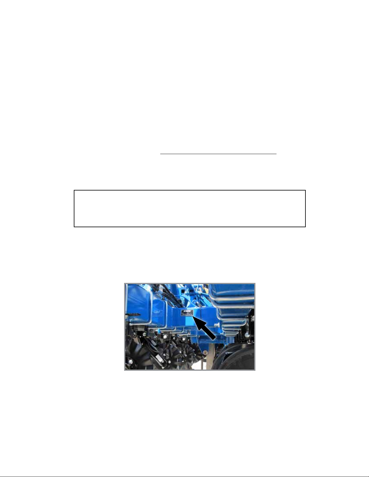
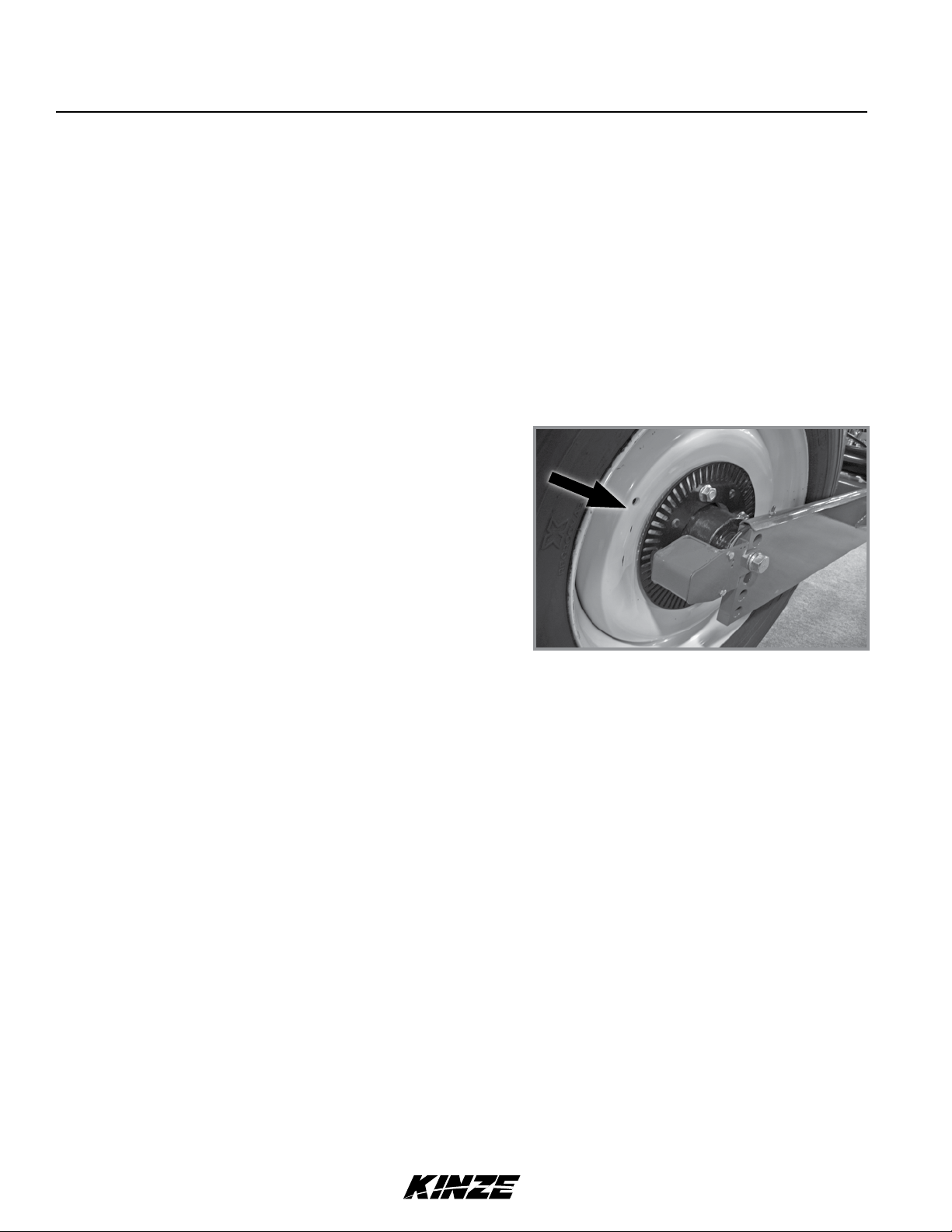
The serial number plate is located on the planter frame as shown below. The serial number provides important information
about your planter and is needed to obtain correct replacement parts. Always provide model number and serial number
to your Kinze Dealer when ordering parts or when contacting Kinze Manufacturing, Inc.
Kinze®, and the Kinze® logo are registered trademarks of Kinze Manufacturing, Inc.
Page 2

This page intentionally left blank.
Page 3

Predelivery/Delivery Checklist
Model 3660M0260-01
TO THE DEALER
Predelivery service includes assembly, lubrication, adjustment and test. This service helps ensure planter is delivered
to retail customer/end user ready for field use.
PREDELIVERY CHECKLIST
Use the following checklist after planter is completely assembled. Check off each item as it is found satisfactory or after
proper adjustment is made.
Center pivot base mounting and transport wheel spindle hex head cap screws torqued to 450 ft-lb (610.1 n-m).
Row units properly spaced and optional attachments correctly assembled.
Row marker assemblies installed and adjusted at each end of the planter.
Vacuum and bulk fill components properly installed (as applicable).
All grease fittings in place and lubricated.
All working parts move freely, bolts are tight, and cotter pins are spread.
Check all drive chains for proper tension and alignment (as applicable).
Check for oil leaks and proper hydraulic operation.
Hydraulic hoses correctly routed to prevent damage.
Inflate tires to specified air pressure and torque wheel lug bolts and lug nuts as specified in the manual.
All safety decals correctly located and legible. Replace if damaged.
All reflective decals and SMV sign correctly located and visible when the planter is in transport position.
Safety/warning lights correctly installed and working properly.
Paint all parts scratched during shipment or assembly.
All safety lockup devices on the planter and correctly located.
Auxiliary safety chain properly installed and hardware torqued to specification.
Vacuum fan PTO-driven pump correctly attached to tractor. Oil reservoir filled to capacity and system inspected for
leaks (If applicable).
Control box properly installed in tractor. All cables correctly routed and secure (hydraulic drive only).
Planter has been thoroughly checked and to the best of my knowledge is ready for delivery to the customer.
(Signature Of Set-Up Person/Dealer Name/Date)
OWNER REGISTER
Name Delivery Date
Street Address Model No. 3660 Serial No.
City, State/Province Dealer Name
ZIP/Postal Code Dealer No.
Rev. 02/19 1
TM
Page 4

Predelivery/Delivery Checklist
M0260-01Model 3660
DELIVERY CHECKLIST
Use the following checklist at time planter is delivered as a reminder of very important information which should be
conveyed to retail customer/end user. Check off each item as it is fully explained.
Check proper operation of vacuum fan, bulk fill fan, and PTO-driven pump (If applicable) with tractor used with planter.
Life expectancy of this or any other machine is dependent on regular lubrication as directed in the Operator Manual.
All applicable safety precautions.
Along with retail customer/end user, check reflective decals and SMV sign are clearly visible with planter in transport
position and attached to tractor. Check safety/warning lights are in working condition. Tell retail customer/end user
to check federal, state/provincial, and local regulations before towing or transporting on a road or highway.
Give Operator Manual, Parts Manual, and all Instruction Sheets to retail customer/end user and explain all operating
adjustments.
Read warranty to retail customer/end user.
Complete Warranty and Delivery Report form.
To the best of my knowledge this machine has been delivered ready for field use and customer has been fully
informed as to proper care and operation.
(Signature Of Delivery Person/Dealer Name/Date)
AFTER DELIVERY CHECKLIST
The following is a list of items we suggest to check during the first season of use of the equipment.
Check planter performance with retail customer/end user.
Check performance of vacuum or mechanical seed metering system with retail customer/end user.
Review importance of proper maintenance and adherence to all safety precautions with retail customer/end user.
Check for parts that may need to be adjusted or replaced.
Check all safety decals, reflective decals, and SMV sign are correctly located as shown in the Parts Manual and that
decals are legible. Replace if damaged or missing.
Check safety/warning lights are working properly.
(Signature Of Follow-Up Person/Dealer Name/Date)
All registrations must be submitted online at “business.kinze.com” within 5 business days of delivery.
Retain a copy of this form for auditing purposes.
Tear Along Perforation
2 Rev. 02/19
TM
Page 5

Table of Contents
Model 3660M0260-01
OVERVIEW
To The Owner ..................................1-1
Warranty ......................................1-3
General Information . . . . . . . . . . . . . . . . . . . . . . . . . . . . . . 1-3
Overview ......................................1-3
Specifications. . . . . . . . . . . . . . . . . . . . . . . . . . . . . . . . . . . 1-4
Tractor Hydraulic Requirements. . . . . . . . . . . . . . . . . . . . . 1-5
General Safety Rules. . . . . . . . . . . . . . . . . . . . . . . . . . . . . 1-6
Safety Precautions. . . . . . . . . . . . . . . . . . . . . . . . . . . . . . . 1-7
MACHINE OPERATION
Planter Lift Safety Lockup .........................2-1
Row Marker Safety Lockup ........................2-1
Tongue Safety Pin ...............................2-2
Transport Latch Locking Pin .......................2-2
Initial Preparation ................................2-3
Tractor Mount PTO Pump/Oil Cooler Opt (Hyd Drive) ....2-4
Tractor Requirements. . . . . . . . . . . . . . . . . . . . . . . . . . . . . 2-5
Tractor Preparation and Hookup ....................2-5
Level Planter ...................................2-9
Ridge Planting . . . . . . . . . . . . . . . . . . . . . . . . . . . . . . . . . 2-10
True Depth Hydraulic System Overview .............2-11
True Depth Filter ...............................2-12
Control Console Operation .......................2-13
Hydraulic Seed Rate Drive. . . . . . . . . . . . . . . . . . . . . . . . 2-14
Hall Effect Sensor (Hydraulic Drive Only) ............2-14
Hydraulic Weight Transfer Toolbar ..................2-14
Ag Leader Electric Clutches ......................2-14
Transport to Field Sequence ......................2-15
Field Operation ................................2-17
Planting Speed ................................2-18
Field to Transport Sequence ......................2-18
Transport to Field Sequence Using Blue Vantage . . . . . . 2-21
Vacuum System. . . . . . . . . . . . . . . . . . . . . . . . . . . . . . . . 2-22
Digital Vacuum Readout. . . . . . . . . . . . . . . . . . . . . . . . . . 2-22
Vacuum Fan and Bulk Fill Motor Valve Block Assembly
Analog Vacuum or Pressure Gauge. . . . . . . . . . . . . . . . . 2-22
Bulk Fill System . . . . . . . . . . . . . . . . . . . . . . . . . . . . . . . .2-23
Bulk Fill Entrainer Access ........................2-24
Bulk Fill Tanks - Clean Out. . . . . . . . . . . . . . . . . . . . . . . . 2-24
Bulk Fill Scale Package Option ....................2-25
Ag Leader Integra Display . . . . . . . . . . . . . . . . . . . . . . . .2-27
Ag Leader Monitoring Control (PMM) ...............2-27
Ag Leader InCommand 1200 Display ...............2-27
Kinze ISOBUS Option ...........................2-28
Auxiliary Work Lights Package. . . . . . . . . . . . . . . . . . . . . 2-28
Kinze True Depth Display. . . . . . . . . . . . . . . . . . . . . . . . . 2-28
. . . . 2-22
Kinze Blue Vantage .............................2-28
Row Marker Operation ...........................2-29
Row Marker Speed Adjustment . . . . . . . . . . . . . . . . . . . . 2-30
Even-Row Push Row Unit ........................2-30
Row Marker Adjustments. . . . . . . . . . . . . . . . . . . . . . . . . 2-31
Row Marker Even-Row Length Adjustment ...........2-32
Offset Hitch Adjustment . . . . . . . . . . . . . . . . . . . . . . . . . . 2-32
Point Row Clutches .............................2-33
Auxiliary Hydraulic Option ........................2-34
Rear Trailer Hitch ...............................2-35
Field Test .....................................2-36
Field Check Seed Population. . . . . . . . . . . . . . . . . . . . . . 2-36
Determining Pounds Per Acre (Brush-Type Meter) .....2-37
Determining Bushels Per Acre. . . . . . . . . . . . . . . . . . . . . 2-37
Field Check Granular Chemical Application ..........2-38
ROW UNIT OPERATION
Planting Depth . . . . . . . . . . . . . . . . . . . . . . . . . . . . . . . . . .3-1
“V” Closing Wheel Adjustment (Rubber or Cast Iron) ....3-1
Closing Wheel Shield
(Rubber or Cast Iron “V” Closing Wheels) . . . . . . . . . . .3-1
Drag Closing Attachment. . . . . . . . . . . . . . . . . . . . . . . . . . 3-2
Covering Discs/Single Press Wheel Adjustment ........3-2
Seed Hoppers ..................................3-3
Seed Meter Drive Release. . . . . . . . . . . . . . . . . . . . . . . . . 3-3
Row Unit Extension Brackets. . . . . . . . . . . . . . . . . . . . . . . 3-3
Row Unit Chain Routing. . . . . . . . . . . . . . . . . . . . . . . . . . . 3-4
Quick Adjustable Down Force Springs Option
(Standard or Heavy Duty) .......................3-5
Interplant Push Row Unit Lockups. . . . . . . . . . . . . . . . . . 3-11
Brush-Type Seed Meter . . . . . . . . . . . . . . . . . . . . . . . . . .3-14
Brush-Type Seed Meter 2.0 .......................3-15
Finger Pickup Seed Meter . . . . . . . . . . . . . . . . . . . . . . . .3-16
Vacuum Settings ...............................3-17
Seed Meter Cleanout. . . . . . . . . . . . . . . . . . . . . . . . . . . . 3-21
Frame Mounted Coulter (Pull Row) .................3-24
Residue Wheels (Frame Mounted Coulter) ...........3-24
Row Unit Mounted Disc Furrower (Pull Row) .........3-25
Row Unit Mounted Bed Leveler (Pull Row) ...........3-25
Row Unit Mounted Residue Wheel .................3-26
Spiked Closing Wheel ...........................3-27
Row Unit Mounted No Till Coulter ..................3-28
Coulter Mounted Residue Wheels . . . . . . . . . . . . . . . . . . 3-28
GFX Hydraulic Row Cleaners .....................3-29
Granular Chemical Hopper and Drive ...............3-30
Spring Tooth Incorporator ........................3-30
Granular Chemical Banding Options . . . . . . . . . . . . . . . .3-31
Granular Chemical Bander Shield . . . . . . . . . . . . . . . . . .3-31
Rev. 7/19 i
TM
Page 6

Table of Contents
M0260-01Model 3660
FERTILIZER
Double Disc Fertilizer Opener ......................4-1
Notched Single Disc Openers ......................4-2
Residue Wheel Attachment for
Notched Single Disc Fertilizer Opener .............4-4
Depth/Gauge Wheel Attachment for
Notched Single Disc Fertilizer Opener .............4-4
HD Single Disc Fertilizer Opener ....................4-5
Liquid Fertilizer Attachment ........................4-7
RATE CHARTS . . . . . . . . . . . . . . . . . . . . . . . . . . . . 5-1
LUBRICATION AND MAINTENANCE
Lubrication . . . . . . . . . . . . . . . . . . . . . . . . . . . . . . . . . . . . .6-1
Lubrication Symbols .............................6-1
Sealed Bearings ................................6-1
Bushings ......................................6-3
Center Post ....................................6-4
Liquid Fertilizer Piston Pump ......................6-4
Crankcase Oil Level. . . . . . . . . . . . . . . . . . . . . . . . . . . . . . 6-4
PTO Pump Shaft Coupling
(Tractor Driven PTO Pump and Oil Cooler Option)
Grease Fittings .................................6-6
Mounting Bolts and Hardware .....................6-10
Tractor Driven PTO Pump and Oil Cooler Option ......6-14
Finger Pickup Seed Meter Inspection/Adjustment. . . . . . 6-15
Cleaning Finger Pickup Seed Meter For Storage ......6-16
Brush-Type Seed Meter Maintenance ...............6-17
Cleaning Brush-Type Seed Meter For Storage ........6-18
Vacuum Manifold Maintenance ....................6-18
Vacuum Seed Meter Maintenance. . . . . . . . . . . . . . . . . . 6-19
Seed Meter Cleanout. . . . . . . . . . . . . . . . . . . . . . . . . . . . 6-19
Drag Closing Attachment ........................6-20
Gauge Wheel Adjustment ........................6-20
Gauge Wheel Arm Bushing and/or Seal Replacement
Gauge Wheel Arm Pivot Spindle Replacement . . . . . . . . 6-21
15" Seed Opener Disc Blade/Bearing Assembly .......6-22
Seed Tube Guard/Inner Scraper ...................6-24
Frame Mounted Coulter .........................6-24
Residue Wheels
(For Use With Frame Mounted Coulter) ...........6-24
Row Unit Mounted Disc Furrower ..................6-25
Row Unit Mounted Bed Leveler . . . . . . . . . . . . . . . . . . . . 6-25
Row Unit Mounted No Till Coulter ..................6-25
Spiked Closing Wheel ...........................6-26
Coulter Mounted Residue Wheels . . . . . . . . . . . . . . . . . . 6-26
Row Unit Mounted Residue Wheel .................6-26
Granular Chemical Attachment ....................6-26
GFX Hydraulic Row Cleaners .....................6-27
Spring Tooth Incorporator ........................6-27
Rev. 7/19
ii
. . . . . 6-5
. . . . 6-21
Pressure Reducing Relief Valve. . . . . . . . . . . . . . . . . . . . 6-28
Row Marker Bearing Lubrication or Replacement . . . . . . 6-30
Wheel Bearing Repack or Replacement .............6-31
Pneumatic Down Pressure Air Compressor Tank ......6-37
Fertilizer Check Valve Cleaning and Repair ...........6-38
Piston Pump Storage. . . . . . . . . . . . . . . . . . . . . . . . . . . . 6-38
Hydraulic Hose Life .............................6-46
ISOBUS Implement Cable . . . . . . . . . . . . . . . . . . . . . . . . 6-56
ISOBUS CAN Jumper Cable . . . . . . . . . . . . . . . . . . . . . .6-56
Product Control Module Cable. . . . . . . . . . . . . . . . . . . . . 6-57
Implement Switch Extension Cable . . . . . . . . . . . . . . . . .6-58
Section Adapter Cable - 12 Row ...................6-59
Section Adapter Cable - 16 Row ...................6-59
Clutch Cable - 12 Row ...........................6-60
Clutch Cable - 16 Row ...........................6-61
True Depth - Interconnect ........................6-62
True Depth Option- Hydraulic Schematic
Main Down Force Valve Block ...................6-63
True Depth Option -
Push Units 1-8 ................................6-64
True Depth Option -
Push Units 9-15 ...............................6-65
True Depth Option -
Row Units 1-8 .................................6-66
True Depth Option -
Row Units 9-16 . . . . . . . . . . . . . . . . . . . . . . . . . . . . . . . .6-67
True Depth Option - Hydraulic Schematic -
SCV Input Option ............................6-68
True Depth Option - Hydraulic Schematic -
Battery Pack Input Option . . . . . . . . . . . . . . . . . . . . . . 6-69
True Depth Option - Hydraulic Schematic -
Bulk Fill Input Option . . . . . . . . . . . . . . . . . . . . . . . . . . 6-70
True Depth Option - Hydraulic Schematic -
Even Row Option. . . . . . . . . . . . . . . . . . . . . . . . . . . . . 6-71
Hydraulic
Hydraulic
Hydraulic
Hydraulic
Schematic -
Schematic -
Schematic -
Schematic -
TROUBLESHOOTING
Blue Drive ....................................7-10
Bulk Fill .......................................7-1
Closing Wheel ..................................7-1
GFX Hydraulic Row Cleaners ......................7-1
Lift Circuit Troubleshooting. . . . . . . . . . . . . . . . . . . . . . . . . 7-2
Piston Pump ...................................7-3
PTO Pump Drive and Oil Cooler Option ..............7-3
Rotation Circuit .................................7-4
Row Marker Operation ............................7-4
Seed Meter (Brush-Type). . . . . . . . . . . . . . . . . . . . . . . . . . 7-5
Seed Meter (Finger Pickup) .......................7-8
Solenoid Valve . . . . . . . . . . . . . . . . . . . . . . . . . . . . . . . . . . 7-9
Tongue Cylinder Circuit ...........................7-9
Vacuum Seed Meter .............................7-6
Wing Lock Cylinder Circuit. . . . . . . . . . . . . . . . . . . . . . . . 7-10
TM
Page 7
To The Owner
Model 3660M0260-01
Kinze Manufacturing, Inc. thanks you for your patronage. We appreciate your confidence in Kinze farm machinery. Your
Kinze planter has been carefully designed to provide dependable operation in return for your investment.
This manual has been prepared to aid you in the operation and maintenance of the planter. It should be
considered a permanent part of the machine and remain with the machine when you sell it.
It is the responsibility of the user to read and understand the Operator Manual in regards to safety, operation,
lubrication and maintenance before operation of this equipment. It is the user’s responsibility to inspect and service
the machine routinely as directed in the Operator Manual. We have attempted to cover all areas of safety, operation,
lubrication and maintenance; however, there may be times when special care must be taken to fit your conditions.
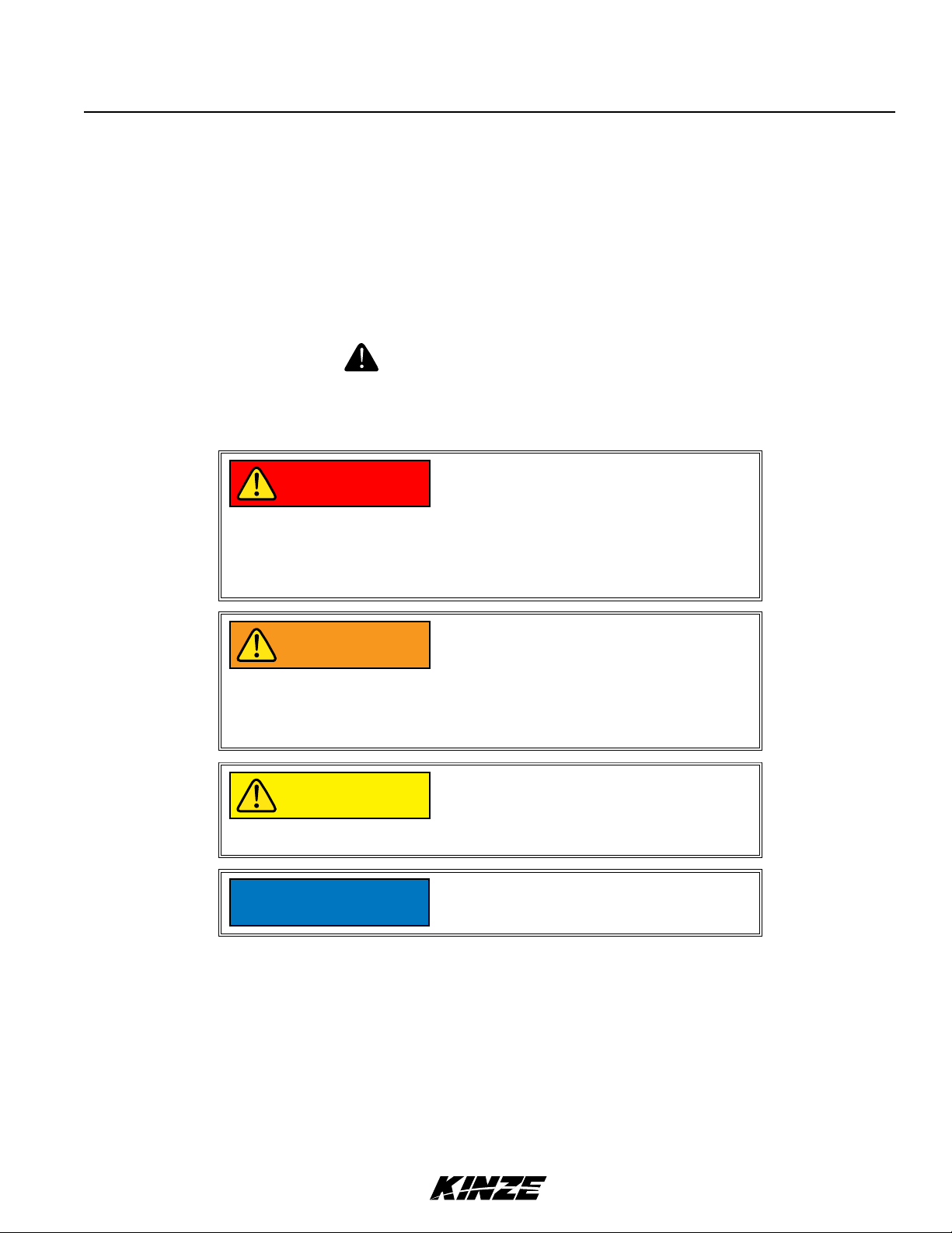
Throughout this manual the symbol and the words DANGER, WARNING, and CAUTION are used to call
attention to safety information that if not followed, will or could result in death or injury. NOTICE and NOTE are used to
call your attention to important information. The definition of each of these terms follows:
Indicates an imminently hazardous
DANGER
situation that, if not avoided, will
result in death or serious injury. This
signal word is to be limited to the most
extreme situations, typically for machine
components which, for functional
purposes, cannot be guarded.
Indicates a potentially hazardous
WARNING
CAUTION
NOTICE
NOTE: Special point of information or machine adjustment instructions.
situation that, if not avoided, could result
in death or serious injury, and includes
hazards that are exposed when guards
are removed. It may also be used to alert
against unsafe practices.
Indicates a potentially hazardous
situation that, if not avoided, may result
in minor or moderate injury. It may also
be used to alert against unsafe practices.
Used to address safety practices not
related to personal injury.
Rev. 02/19 1-1
TM
Page 8
To The Owner
M0260-01Model 3660
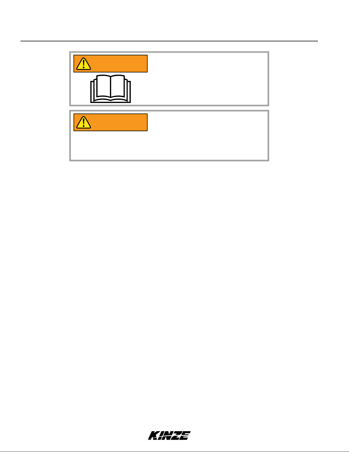
Improperly operating or working on
WARNING
WARNING
NOTE: Some photos in this manual may have been taken of prototype machines. Production machines may
vary in appearance.
this equipment could result in death
or serious injury. Read and follow all
instructions in Operator Manual before
operating or working on this equipment.
Some photos in this manual may show
safety covers, shields, or lockup devices
removed for visual clarity. NEVER
OPERATOR OR WORK ON machine
without all safety covers, shields, and
lockup device in place as required.
NOTE: Some photos and illustrations in this manual show optional attachments installed. Contact your Kinze
Dealer for purchase of optional attachments.
1-2 Rev. 02/19
TM
Page 9

Overview
Model 3660M0260-01
WARRANTY
The Kinze Limited Warranty for your new machine is stated on the retail purchaser’s copy of the Warranty And Delivery
Receipt form. Additional copies of the Limited Warranty can be obtained through your Kinze Dealer.
Warranty, within the warranty period, is provided as part of Kinze’s support program for registered Kinze products
which have been operated and maintained as described in this manual. Evidence of equipment abuse or modification
beyond original factory specifications will void the warranty. Normal maintenance, service and repair is not covered by
Kinze warranty.
To register your Kinze product for warranty, a Warranty And Delivery Receipt form must be completed by the Kinze
Dealer and signed by the retail purchaser, with copies to the Dealer, and to the retail purchaser. Registration must be
completed and submitted to Kinze Manufacturing, Inc. within 5 business days of delivery of the Kinze product to the
retail purchaser. Kinze Manufacturing, Inc. reserves the right to refuse warranty on serial numbered products which
have not been properly registered.
If service or replacement of failed parts which are covered by the Limited Warranty are required, it is the user’s
responsibility to deliver the machine along with the retail purchaser’s copy of the Warranty And Delivery Receipt to
the Kinze Dealer for service. Kinze warranty does not include cost of travel time, mileage, hauling or labor. Any prior
arrangement made between the Dealer and the retail purchaser in which the Dealer agrees to absorb all or part of this
expense should be considered a courtesy to the retail purchaser.
Kinze warranty does not include cost of travel time, mileage, hauling, or labor.
GENERAL INFORMATION
The Model 3660 Twin-Line planter is available with vacuum or mechanical meters, conventional hoppers or bulk
fill, Interplant, liquid fertilizer, and various other options. Contact your Kinze Dealer for available options and
configurations. To obtain the most recent version of your publication, please contact your Kinze dealer.
Model 3660 16 Row Bulk Fill Planter
Information used in these instructions was current at time of printing. However, due to Kinze’s ongoing product
improvement, production changes may cause your machine to appear slightly different in detail. Kinze Manufacturing,
Inc. reserves the right to change specifications or design without notice and without incurring obligation to install the
same on machines previously manufactured.
Right hand (R.H.) and left hand (L.H.), as used throughout this manual, are determined by facing direction machine
travels in use unless otherwise stated.
Rev. 02/19 1-3
TM
Page 10

Specifications
M0260-01Model 3660
Specification Conventional Hoppers
Number of Rows 12R N 30 16R N 30
Weight Empty (Mechanical) 15,040 lb (6823 kg) 18,460 lb (8374 kg) - 19,100 lb (8663.61 kg)
Weight Empty (Vacuum) 15,450 lb (7008 kg) 18,400 lb (8347 kg)
Transport Height 11' 11" (3.6M) 11' 11" (3.6M)
Planting Length 23' 9" (7.2M) 26'3" (8M)
Transport Length 39' 2" (12M) 49'2" (15M)
Planting Width 32' 11" (10M) 42'11" (13.1M)
Transport Width 11' 2" (3.4M) 11'2" (3.4M)
Seed Capacity 1.75 bu. (Vacuum / Hopper); 1.90 bu. (Mechanical / Hopper)
Transport Tire Size
Field Tire Size
Field Lift
Row Markers
Four 41" x 11" R22.5 radial load range 'H' tubeless rib implement.
7.50" x 20" 8 ply tubeless rib implement tires.
Two master center rockshaft/four wing wheel slave rephasing cylinders.
Independently controlled, three stage, low profile, w/disk blade depth bands.
Specification Bulk Fill
Number of Rows 12R N 30 16R N 30
Weight Empty (Mechanical) 17,120 lb (7766 kg) - 17,450 lb (7916 kg) 20,020 lb (9081 kg) - 20,400 lb (9254 kg)
Weight Empty (Vacuum) 17,120 lb (7766 kg) - 17,450 lb (7916 kg) 20,020 lb (9081 kg) - 20,400 lb (9254 kg)
Transport Height 12' 11" (4M) 12'11" (4M)
Planting Length 23' 9" (7.2M) 26'3" (8M)
Transport Length 39' 2" (12M) 49'2" (15M)
Panting Width 32' 11" (10M) 42'11" (13.1M)
Transport Width 11' 2" (3.4M) 11'2" (3.4M)
Seed Capacity 110 bu.
Bulk Fill Fill Height
8' 5" (2.6M)
(planting position)
Transport Tire Size
Field Tire Size
Field Lift
Four 41" x 11" R22.5 radial load range 'H' tubeless rib implement.
7.50" x 20" 8 ply tubeless rib implement.
Two master center rockshaft/four wing wheel slave rephasing cylinders.
Row Markers
1-4 Rev. 02/19
Independently controlled, three stage, low profile, w/disk blade depth bands.
TM
Page 11

Model 3660M0260-01
TRACTOR HYDRAULIC REQUIREMENTS
Configuration No Optional Pumps Tractor Mounted Pump
Mechanical Meter 3 SCV 20 gpm min.
Vacuum Meter
1
Bulk Fill (with Mechanical
3
Meter)
ASD (with Vacuum)
1
External case drain required for vacuum hydraulic circuits when no optional pumps are used.
2
Pump PTO Requirements: Tractor mounted - 1000 rpm, 1" diameter shaft. Planter mounted - 1000 rpm, 1¾"
3
4 SCV 40 gpm min. 3 SCV 25 gpm min.
4 SCV 30 gpm min. 3 SCV 20 gpm min.
5 SCV 50 gpm min. 4 SCV 40 gpm min. 3 SCV 25 gpm min.
diameter shaft.
3
Tractor Horsepower Requirement: 225 horsepower or greater class tractor is required to effectively operate a fully
optioned (Bulk Fill, Interplant, Vacuum) 3660 planter.
2
Planter Mounted Pump
TRACTOR HYDRAULIC REQUIREMENTS - SPRING & PDP DOWN FORCE - 12R & 16R
Configuration No Optional Pumps Tractor Mounted Pump
w/o Interplant w/ Interplant
Mechanical Meter 3 SCV 20 gpm min. NA
Vacuum Meter
1
Bulk Fill (with Mechanical Meter)
3
4 SCV 40 gpm min. 3 SCV 25 gpm min.
4 SCV 30 gpm min. 3 SCV 20 gpm min.
Bulk Fill (with Vacuum) 5 SCV 50 gpm min. 4 SCV 40 gpm min.
Bulk Fill, Vacuum, Blue Drive 5 SCV 50 gpm min. 4 SCV 40 gpm min.
1
External case drain required for vacuum hydraulic circuits when no optional pumps are used.
2
Pump PTO Requirements: Tractor mounted - 1000 rpm, 1" diameter shaft. Planter mounted - 1000 rpm, 1¾"
diameter shaft.
3
Tractor Horsepower Requirement: 225 horsepower or greater class tractor is required to effectively operate a fully
optioned (Bulk Fill, Interplant, Vacuum) 3660 planter.
2
2
TRACTOR HYDRAULIC REQUIREMENTS - TRUE DEPTH DOWN FORCE - 16R
Configuration Without Interplant With Interplant
No
Optional
Pump
Mechanical Meter 3 SCV
Vacuum Meter
1
Bulk Fill (with Mechanical Meter)
4 SCV
3
4 SCV
Bulk Fill (with Vacuum) 5 SCV
Bulk Fill, Vacuum, Blue Drive 5 SCV
1
External case drain required for vacuum hydraulic circuits when no optional pumps are used.
2
Pump PTO Requirements: Tractor mounted - 1000 rpm, 1" diameter shaft. Planter mounted - 1000 rpm, 1¾"
24 gpm
44 gpm
34 gpm
54 gpm
54 gpm
†
†
†
†
†
Mounted
4 SCV
4 SCV
4 SCV
4 SCV
Tractor
2
Pump
NA 4 SCV
†
†
†
†
5 SCV
4 SCV
5 SCV
5 SCV
29 gpm
24 gpm
44 gpm
44 gpm
No
Optional
Pump
28 gpm
48 gpm
38 gpm
58 gpm
58 gpm
†
†
†
†
†
diameter shaft.
3
Tractor Horsepower Requirement: 225 horsepower or greater class tractor is required to effectively operate a fully
optioned (Bulk Fill, Interplant, Vacuum) 3660 planter.
†
Minimum
Rev. 02/19 1-5
TM
Mounted
4 SCV
4 SCV
4 SCV
4 SCV
Tractor
Pump
NA
33 gpm
28 gpm
48 gpm
48 gpm
2
†
†
†
†
Page 12

General Safety Rules
M0260-01Model 3660
1. Read and understand instructions provided in this
manual and warning labels. Review these instructions
frequently!
2. This machine is designed and built with your safety
in mind. Do not make any alterations or changes to this
machine. Any alteration to design or construction may
create safety hazards.
3. A large portion of farm accidents happen from fatigue
or carelessness. Safe and careful operation of tractor
and planter will help prevent accidents.
4.
Never allow planter to be operated by anyone
unfamiliar with operation of all functions of the unit.
Operators must read and thoroughly understand all
instructions given in this manual before operating or
working on equipment.
5. Be aware of bystanders, particularly children! Always
look around to make sure it is safe to start tow vehicle
engine or move planter. This is particularly important
with higher noise levels and quiet cabs, as you may not
hear people shouting.
6. Make sure planter weight does not exceed towing
capacity of tractor, or bridge and road limits. This is
critical to maintain safe control and prevent death or
injury, or property and equipment damage.
15. Use of aftermarket hydraulic, electric, or PTO drives
may create serious safety hazards to you and people
nearby. If you install such drives, follow all appropriate
safety standards and practices to protect you and others
near this planter from injury.
16. Follow all federal, state/provincial, and local
regulations when towing farm equipment on a public
highway. Use safety chain (not an elastic or nylon/plastic
tow strap) to retain connection between towing and
towed machines in the event of primary attaching system
separation.
17. Make sure all safety/warning lights, SMV sign, and
reflective decals are in place and working properly
before transporting the machine on public roads.
18. Limit towing speed to 15 MPH. Tow only with farm
tractor of a minimum 90 HP. Allow for unit length when
making turns.
19. Reduce speed prior to turns to avoid the risk of
overturning. Always drive at a safe speed relative to local
conditions and ensure your speed is slow enough for a
safe emergency stop.
20. Chemical application is often an integral part of
planting. Follow label instructions for proper chemical
mixing, handling and container disposal methods.
7. Never ride or allow others to ride on planter.
8. Store planter in an area away from human activity. DO
NOT permit children to play on or around the stored unit.
9. Keep hands, feet, and clothing away from moving
parts. Do not wear loose-fitting clothing which may catch
in moving parts.
10. Always wear protective clothing, shoes, gloves,
hearing, and eye protection applicable for the situation.
11. Do not allow anyone to stand between tongue or
hitch and towing vehicle when backing up to planter.
13. Prevent electrocution, other injuries, or property
and equipment damage. Watch for obstructions such as
wires, tree limbs, etc. when operating machine. Be aware
of clearances during turns and when folding/unfolding
planter.
14. Reinstall all guards removed for maintenance
activities. Never leave guards off during operation.
21. Be familiar with safety procedures for immediate first
aid should you accidentally contact chemical substances.
22. Use the proper protective clothing and safety
equipment when handling chemicals.
23. Chemicals are supplied with Material Safety Data
Sheets (MSDS) that provide full information about the
chemical, its effects on exposure, and first aid needs
in the event of an emergency. Keep your MSDS file
up-to-date and available for first responders in case of
emergency.
24. When servicing ground engaging components such
as opening disks and firming points, use special care to
avoid points and edges worn sharp during use.
25. Use professional help if you are unfamiliar with
working on hydraulic systems. Pressurized hydraulic fluid
can penetrate body tissue and result in death, serious
infection, or other injuries.
1-6 Rev. 02/19
TM
Page 13

Safety Precautions
Model 3660M0260-01
Following are some common hazard warnings associated with this equipment. Pay close attention to all safety,
operating, and maintenance information in this manual and decals applied to your equipment.
Contacting or coming close to power
DANGER
WARNING
lines or other high energy sources will
cause death or serious injury.
Keep away from power lines or high
energy sources at all times.
Improperly operating or working on
this equipment could result in death
or serious injury. Read and follow all
instructions in Operator Manual before
operating or working on this equipment.
WARNING
WARNING
Falling equipment can cause death or
serious injury. Install all lockup devices
or lower planter to ground before
working on equipment.
Explosive separation of rim and tire
parts can cause death or serious injury.
Overinflation, rim and tire servicing,
improper use of rims and tires, or worn
or improperly maintained tires could
result in a tire explosion.
Rev. 02/19 1-7
TM
Page 14

Safety Precautions
M0260-01Model 3660
SAFETY SIGNS AND DECALS
All safety/warning lights, reflective
WARNING
Safety signs and decals are placed on the machine to warn of hazards and provide important operating and maintenance
instructions. Information on these signs are for your personal safety and the safety of those around you. FOLLOW ALL
SAFETY INSTRUCTIONS!
• Keep signs clean so they can be easily seen. Wash with soap and water or cleaning solution as required.
• Replace safety signs if damaged, painted over, or missing.
decals, and SMV sign must be in place
and visible before transporting machine
on public roads or death, serious injury,
and damage to property and equipment
may result. Check federal, state/
provincial, and local regulations before
transporting equipment on public roads.
• Check reflective decals and SMV sign periodically. Replace if they show any loss of of reflective properties.
• When replacing decals, clean machine surface thoroughly with soap and water or cleaning solution to
remove all dirt and grease.
NOTE: Safety sign and decal locations are shown in the Parts Manual for this machine.
NOTE: Style and locations of SMV sign, reflective decals, and safety/warning lights conform to ANSI/ASABE
S279.14 JUL 2008 and ANSI/ASABE S276.6 JAN 2005.
1-8 Rev. 02/19
TM
Page 15
PLANTER LIFT SAFETY LOCKUP
WARNING
Machine Operation
Model 3660M0260-01
Uncontrolled movement of equipment
can cause loss of control and could
result in death, serious injury, or damage
to property and equipment. Install
all safety pins before transporting
equipment.
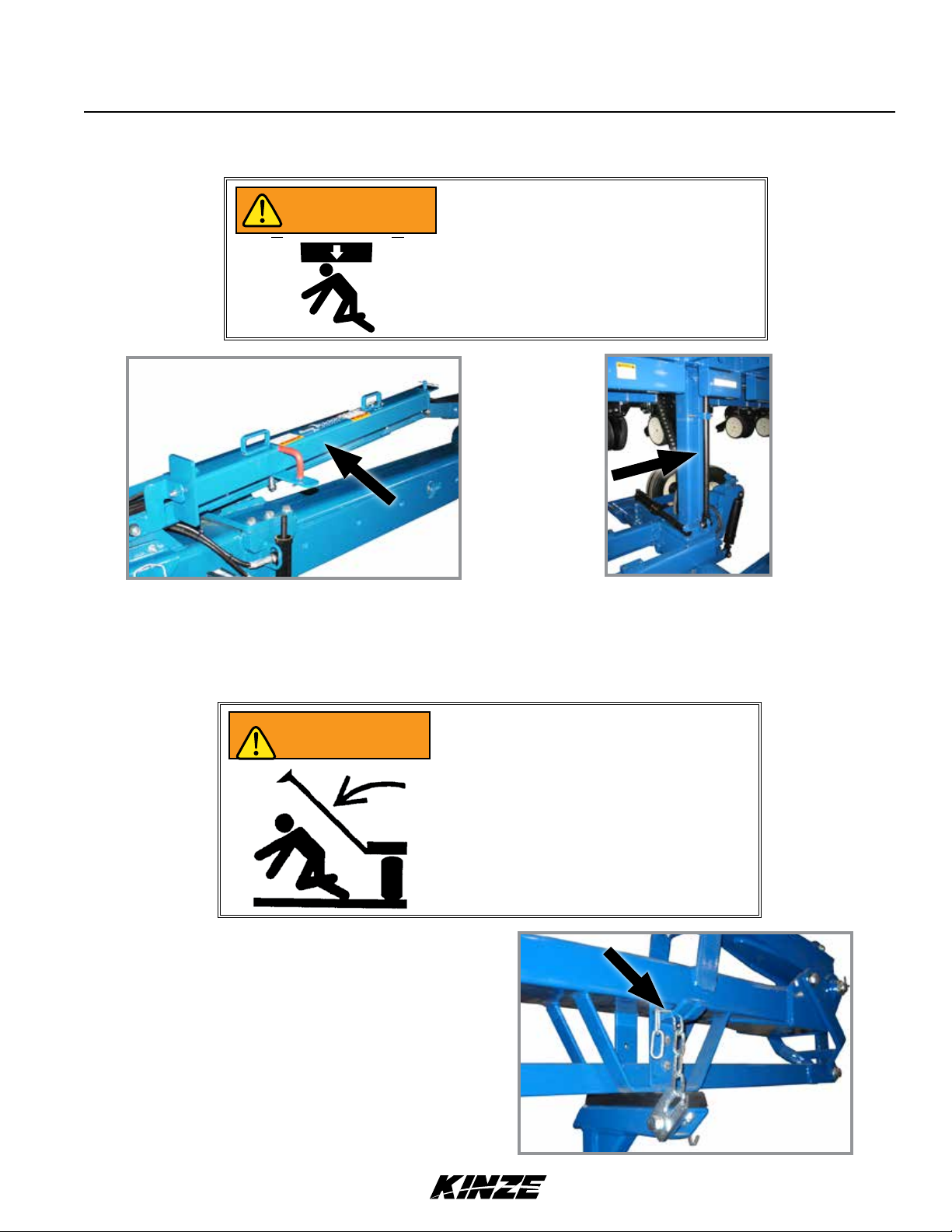
Safety lockup in storage position
Planter lift safety lockup is installed between center post and lift cylinder. It is held in place by a clevis pin near the base
of the lift cylinder rod. Remove safety lockup and store on hose take-up for field operation.
Safety lockup in transport/maintenance position
ROW MARKER SAFETY LOCKUP
Row marker can lower at any time and
WARNING
Always install row marker lockups when working or
transporting planter.
Connect chain between marker stand and second
stage of marker assembly.
could cause death or serious injury. Stay
away from row markers! Install safety
lockup device when not in use.
Row marker safety lockup installed
Rev. 02/19 2-1
TM
Page 16
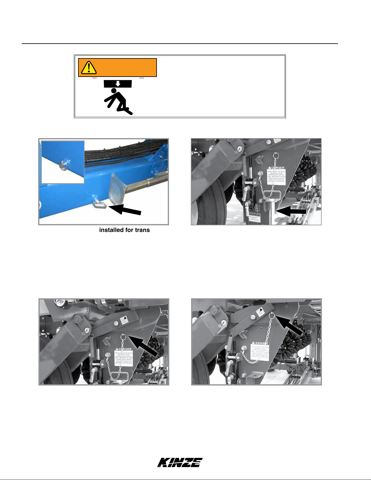
TONGUE SAFETY PIN
Snap pin
WARNING
Machine Operation
M0260-01Model 3660
Uncontrolled movement of equipment
can cause loss of control and could
result in death, serious injury, or damage
to property and equipment. Install
all safety pins before transporting
equipment.
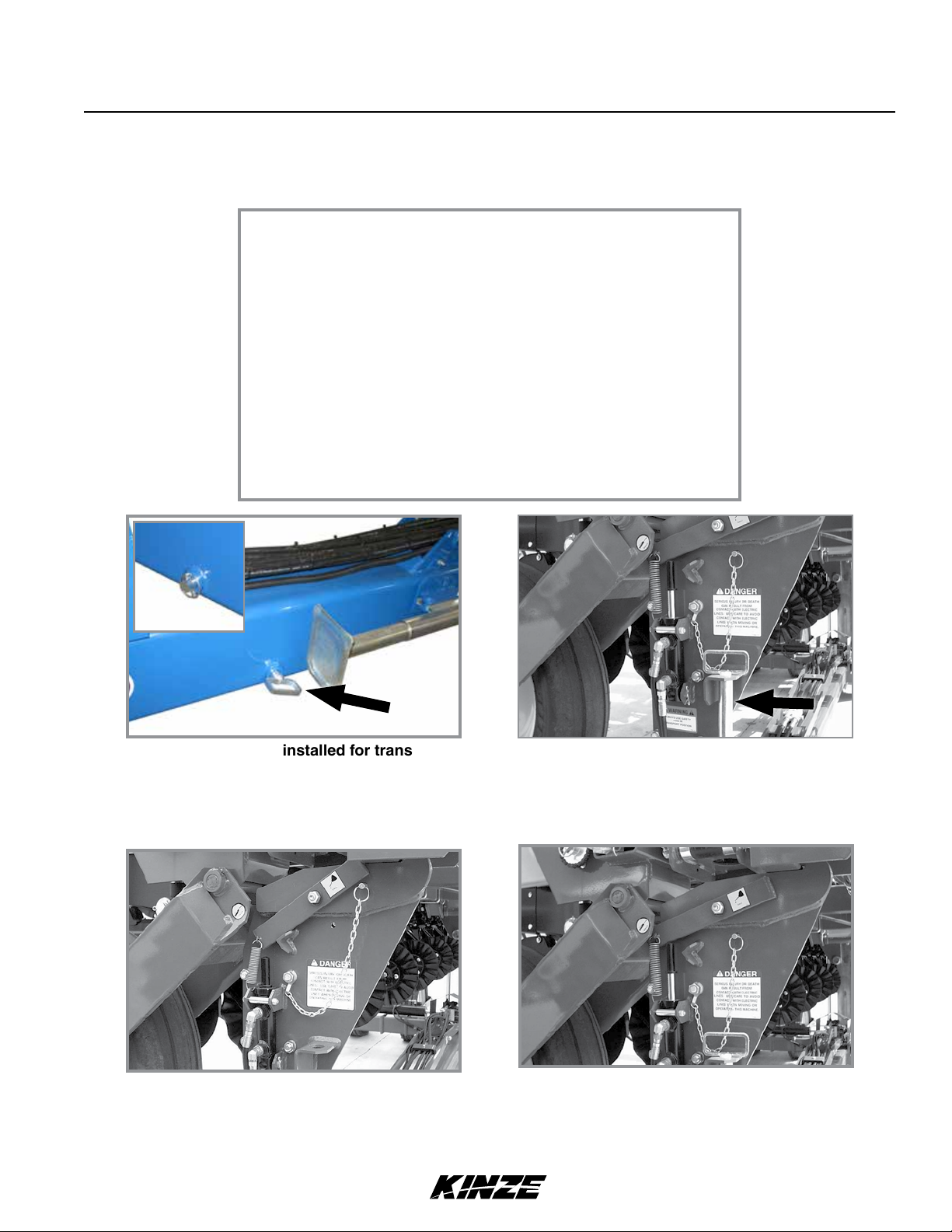
Tongue safety pin installed for transport
Never transport planter without installing tongue safety pin. Tongue safety pin prevents tongue cylinder from retracting
should hydraulic failure occur or a sudden stop be made when transporting planter.
Secure safety pin in hitch with snap pin. Remove tongue safety pin and store in bracket on transport latch post at center
of planter for field operation.
Tongue safety pin stored for field operation
TRANSPORT LATCH LOCKING PIN
Transport latch locking pin stored
Never transport planter without installing transport latch locking pin. Transport latch locking pin prevents latch bar from
disengaging and allowing planter frame to swing away.
Transport latch locking pin installed
Remove transport latch locking pin and store in location provided on latch post for field operation.
2-2 Rev. 02/19
TM
Page 17
Machine Operation
Model 3660M0260-01
INITIAL PREPARATION
Following information is general in nature to aid in preparation of tractor and planter for use, and to provide general
operating procedures. Operator experience, familiarity with the machine, and the following information should combine
for efficient planter operation and good working habits.
Uncontrolled movement of equipment
WARNING
WARNING
can cause loss of control and could
result in death, serious injury, or damage
to property and equipment. Install
all safety pins before transporting
equipment.
Uncontrolled machine movement can
crush or cause loss of control resulting
in death, serious injury, or damage to
property and equipment. Install all safety
lockup devices before working under or
transporting this equipment.
WARNING
WARNING
WARNING
Transporting planter with hoppers over
half full or unevenly loaded can cause
loss of control and could result in death,
serious injury, or damage to property and
equipment. Properly load planter when
transporting. Be aware of extra transport
weight, and road conditions and limits.
To avoid unintended movement of
axle during transport, return all SCV
controls to the neutral position before
transporting machine. DO NOT operate
any hydraulic function while transporting
machine. Doing so could result in death,
serious injury, or damage to property and
equipment.
Transport axle can lower from transport
position without the use of any
controller, causing death, serious injury,
or damage to property and equipment.
Do not operate any hydraulic function
while transporting the planter. Make sure
all transport safety lockups are installed
on the four transport cylinders and all
SCV controls are in their neutral state
before transporting, storing and working
on the planter.
Rev. 02/19 2-3
TM
Page 18
Machine Operation
1. Torque transport wheel "- 18 lug nuts to 180 ft-lb (244 N-m).
2. Inflate tires to the following specifications:
Transport (center section) 255-70R 22.5 (“224” rim)
75 psi (517.1 kPa) recommended/75 psi (517.1 kPa) max.
Transport (center section) 255-70R 22.5" (“276” rim)
75 psi (517.1 kPa) recommended/100 psi (689.4 kPa) max.
M0260-01Model 3660
Transport
Ground drive (wings) 7.50" x 20" 40 psi (275.7 kPa)
Liquid fertilizer piston pump 7.60" x 15" 40 psi (275.7 kPa)
Ground drive (wing)
Tire locations
3. Lubricate planter and row units following instructions in Lubrication and Maintenance section of this manual.
4. Check all row unit drive chains for proper tension, alignment, and lubrication.
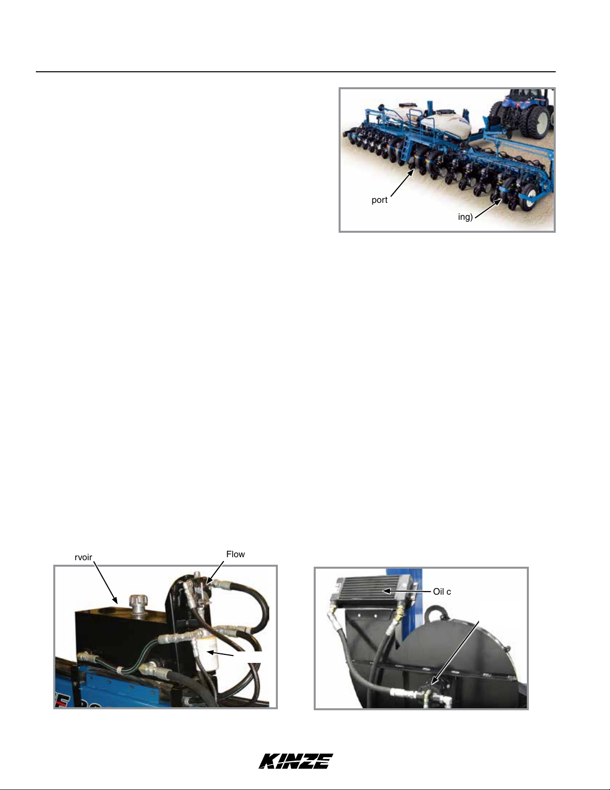
TRACTOR MOUNT PTO PUMP/OIL COOLER OPT (HYD DRIVE)
Tractor driven PTO pump and oil cooler option is for tractors with less than required hydraulic output needed to
operate hydraulic-driven vacuum fan and other planter hydraulic requirements.
A 1000 RPM PTO is required to operate PTO-driven hydraulic pump.
Option consists of a 1"-21 or 1¾"-20 spline,13.5 GPM 2000 PSI tractor mounted pump, 10 gallon capacity hydraulic
reservoir, 15 GPM-rated oil cooler, spin-on 10-micron oil filter, and required hydraulic valves and fittings.
Reservoir
Hydraulic reservoir assembly
* Electric Drive uses a relief valve rather than the flow
2-4 Rev. 02/19
control valve shown.
Flow control valve*
Oil cooler
Hydraulic
motor
Oil filter
Vacuum fan assembly
TM
Page 19
Machine Operation
Model 3660M0260-01
TRACTOR REQUIREMENTS
Consult your dealer for information on horsepower requirements and tractor compatibility. Requirements vary with
planter options, tillage, and terrain.
A 12 volt DC electrical system is required on all sizes.
TRACTOR PREPARATION AND HOOKUP
1.
Adjust tractor drawbar 13-17 inches above ground with hitch pin hole directly below PTO shaft center line. Make
sure drawbar is in a stationary position.
2. Install control console or Blue Vantage Display on tractor
in a convenient location within easy reach of operator and
close to hydraulic controls. Mount control console securely
and route power cord to power source. Control console
operates on 12 volt DC only. If two 12 volt batteries are
connected in series, ALWAYS make power connection on
battery grounded to tractor chassis.
If two 6 volt batteries are connected in series, make sure
power connection provides 12 volt DC across positive
terminal on one battery and negative terminal of second
battery.
3. Back tractor to planter and connect with 1¼" - 1½"
diameter hitch pin. If tractor is not equipped with a hitch
pin locking device, make sure hitch pin is secured with a
locking pin or cotter pin.
Kinze Blue Vantage
Rev. 02/19 2-5
TM
Page 20
Machine Operation
M0260-01Model 3660
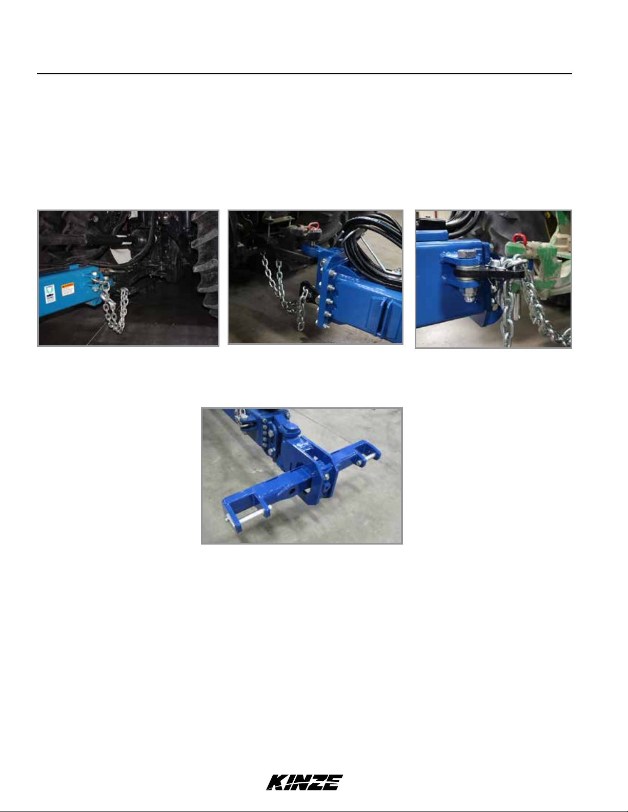
NOTE: DO NOT install safety chain using clevis mounting hardware. Safety chain MUST be installed
separately.
4. Safety chain must be used to keep planter and tractor connected in case of a hitch pin/drawbar failure. Attach
safety chain at an unused clevis mounting hole on the planter hitch. Torque hardware to 840 ft-lb (1138.8 N-m).
NOTE: A 2-Point Hitch Option converts planter from drawn to semi-mounted and is available for use with
Category 3N or 3 three-point hitch designs. Safety chain is not used with 2-point hitch.
2019 Production 2020 Production and On2015 - 2018 Production
Planter/safety chain hookup to tractor
Optional 2-point hitch
2-6 Rev. 02/19
TM
Page 21
WARNING
NOTICE
Machine Operation
Model 3660M0260-01
Pressurized hydraulic fluid can penetrate
body tissue and result in death, serious
infection, or other injuries. Fluid injected
under skin must be IMMEDIATELY
removed by a surgeon familiar with this
type of injury. Make sure connections
are tight and hoses and fittings are
not damaged before applying system
pressure. Leaks can be invisible. Keep
away from suspected leaks. Relieve
pressure before searching for leaks or
performing any system maintenance.
Wipe hose ends to remove any dirt
before connecting couplers to tractor
ports or contamination may cause
equipment failure.
5. Connect hydraulic hoses to tractor ports in a sequence familiar and comfortable to the operator.
6. (If applicable) Connect compressor harness.
7. If equipped with True Depth, attach the True Depth 6 pin connector.
8. If equipped with Blue Drive, attach the Blue Drive 6 pin connector and Ethernet cable to the Blue Vantage display.
Rev. 02/19 2-7
TM
Page 22
Machine Operation
Connect hydraulic motor case drain to a case
NOTICE
NOTICE
PLANTER TO TRACTOR HYDRAULIC CONNECTIONS
Color/Label Machine
Function
Red AA Field Lift ½" Pressure
Red BB ½" Return
Blue AA Planter Fold & Row Marker " Return
Blue BB " Pressure
Black RR Seed Rate Hydraulic Drive
Black PP ½" Pressure
Black RR Seed Rate Hydraulic Drive (Mechanical)
Black PP " Pressure
Green RR Vacuum Fan ¾" Return
Green PP ½" Pressure
Orange CD
Power Pack (Blue Drive)
(Vacuum)
drain return line with zero PSI on tractor.
Failure to connect to a return with zero PSI will
cause hydraulic motor shaft seal damage. DO
NOT connect hydraulic motor case drain to a
SCV outlet or motor return circuit connection.
Contact tractor manufacturer for specific
details on “zero pressure return”.
Always connect hydraulic motor return hose
to tractor motor return port. Do not connect to
tractor SCV unless through a motor spool or
hydraulic motor failure can occur. If a motor
return port is not available on the tractor, the
SCV controlling the bulk fill system MUST be
in the float position before planter is moved in
planting or field raised position when bulk fill
system is not in use.
Hose Size Function
¾" Return
½" Return
" Case Drain
M0260-01Model 3660
Yellow RR Bulk Fill System Pressure Fan ¾" Motor Return
Yellow PP ½" Pressure
Orange CD
Purple RR
Purple PP ½” Pressure
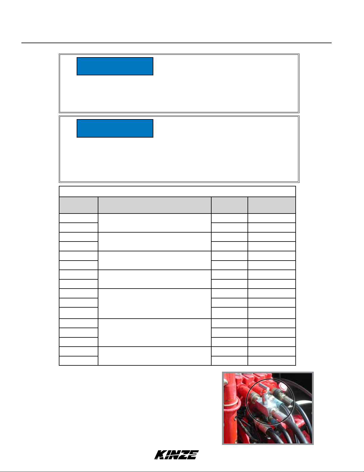
NOTE: Set adjustable flow outlet (SCV) to full flow position.
For tractors not equipped with a method for finite adjustment of
hydraulic flow, Flow Control Needle Valve Kit G1K426 is available
from Kinze Repair Parts through your Kinze Dealer.
2-8 Rev. 02/19
True Depth ” Return
TM
" Case Drain
G1K426 needle valve kit
Page 23
Machine Operation
Model 3660M0260-01
6. Connect ASABE Standards 7 terminal connector for safety/warning lights on planter to ASABE Standards
receptacle on tractor. If your tractor is not equipped with an ASABE Standards receptacle, check with your tractor
manufacturer for availability. Check warning lights on planter work in conjunction with warning lights on tractor.
NOTE: A 12 volt battery connection is required to power the vacuum fan digital gauge. Connect “red” wire to
positive (+) battery terminal and “black” wire to negative (-) battery terminal.
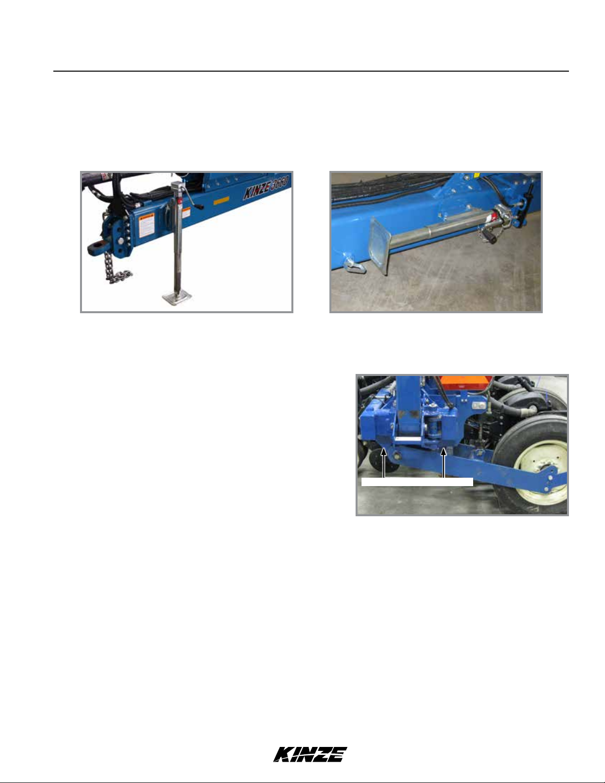
Jack in operating position Jack in storage position
7. Raise jack stand and remount horizontally on storage bracket on opposite side of hitch.
LEVEL PLANTER
Lateral adjustment is maintained by tire pressure. Check tires
are inflated to specification.
Front and rear level adjustment is maintained by hitch clevis
position unless tractor drawbar is adjustable for height. Planter
frame and row unit parallel arms must be level for proper
planter and row unit operation. Bottom of toolbar should be 20"
to 22" from planting surface.
1. Lower planter to planting position and check planter is level
front to rear. Go to step 2 if hitch is too high or low.
NOTE: DO NOT install safety chain using clevis hardware. Move safety chain location if necessary.
2. Remove clevis hitch hex head cap screw and lock nut using a torque wrench. Replace if off-torque is below 75 ft-lb
(101.6 N-m) or there is corrosion or damage.
NOTE: Clevis must be free to move on hitch. DO NOT OVERTIGHTEN hardware.
Level 20" - 22" from ground
Level planter toolbars
3. Align clevis to hitch holes at new location and install hex head cap screw and lock nut. Tighten lock nut until
threads are fully engaged and hex head cap screw and lock nut are firmly against hitch bracket.
NOTE: On planters with push row units and no till coulters, uplift from down force springs or air springs in
pneumatic down pressure system may cause wings to rise slightly in planting position. Problem may be
compounded if static pressure is trapped in planter’s hydraulic lift system which can cause wing cylinders
to extend slightly. Operating tractor’s hydraulic system in float position or moving tractor’s hydraulic lever to
float position briefly to relieve pressure will help maintain proper toolbar height.
Rev. 02/19 2-9
TM
Page 24
Machine Operation
M0260-01Model 3660
4. Field check planter.
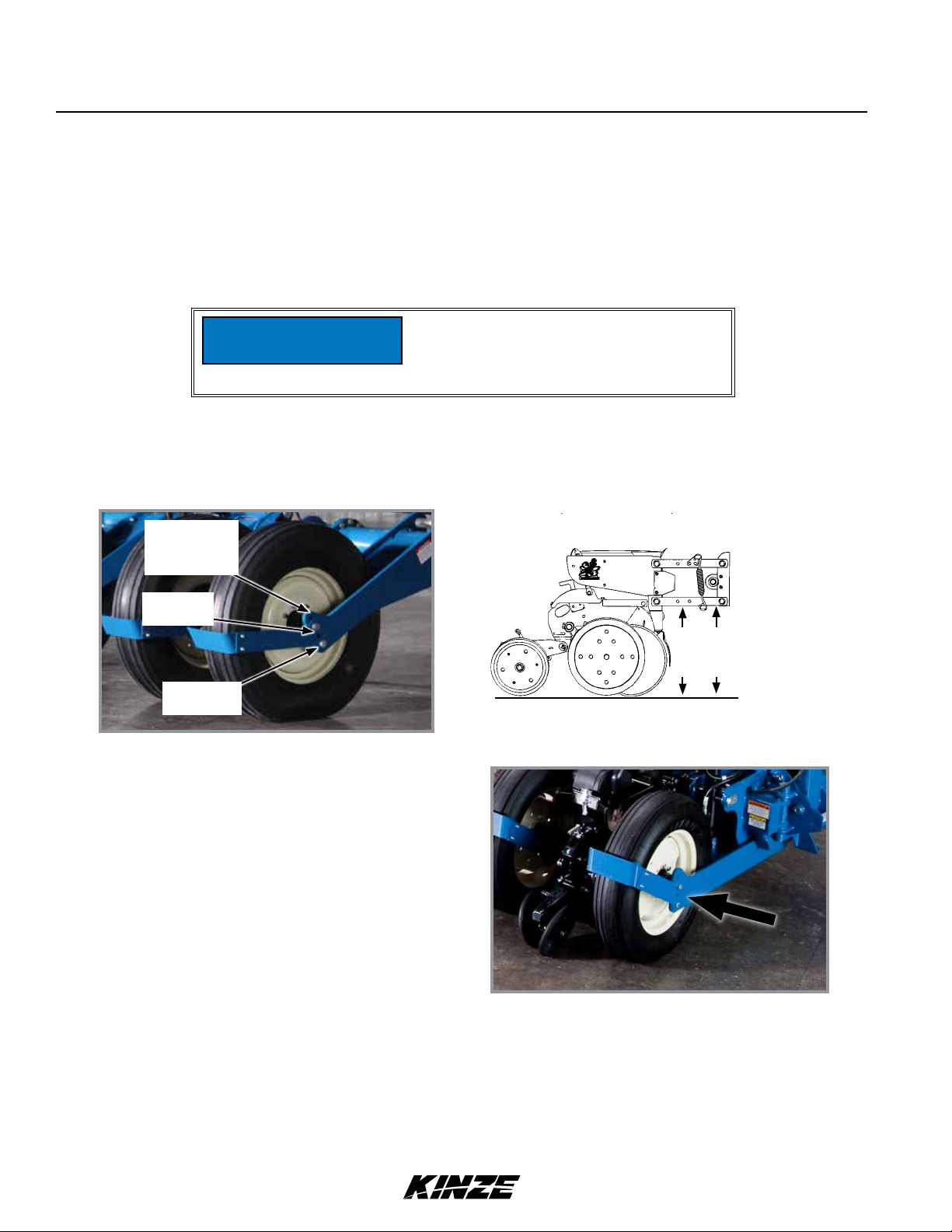
Field and actual planting conditions dictate which transport wheel setting to use so row unit parallel arms are parallel
with ground. It may be necessary to lower ground drive wheels to ensure level lateral toolbar operation if transport
wheels are set in one of the two lower sets of holes. Make a field check when planter is fully loaded with seed,
granular chemicals, fertilizer, etc. to be sure wings are level with center frame. If wings are not level with center frame,
drive wheels and/or transport wheels can be raised or lowered in wheel arms to increase or decrease planter toolbar
height. Raise hitch to ensure level operation.
Component interference can damage
NOTICE
NOTE: To allow adequate drive force after lowering ground drive wheels, it may be necessary to lower
contact drive wheel arms to lower sets of holes in wheel modules and lower down pressure springs to lower
mounting rods on wheel modules.
equipment. Check clearance between
tires and drill shaft U-joint when using
top hole setting.
No till or firm
soil conditions.
(Initial setting)
Soft field
conditions.
Ridge or
bed planting.
Transport wheel adjustment
Keep row unit parallel arms parallel to
ground when adjusting wheel heights.
Parallel
with
ground
Field/wing wheel adjustment
RIDGE PLANTING
Move drive and transport wheels 2" or 4" to lower mounting holes in wheel arms when ridge planting to increase
planter toolbar height. Raise hitch height to ensure level operation.
2-10 Rev. 02/19
TM
Page 25
Machine Operation
TRUE DEPTH HYDRAULIC SYSTEM OVERVIEW
True Depth Pressure Gauge
Model 3660M0260-01
WARNING
Remove all hydraulic power sources and
verify True Depth pressure gauge reads
zero before servicing.
True Depth Cylinder
Flow out of the rod end port of the
WARNING
Rev. 02/19 2-11
cylinder must not be restricted when
pressurizing cap end port as 4.5:1
pressure intensification will occur on
the rod end of the cylinder potentially
resulting in failure of the cylinder and
loss of containment of the piston rod
assembly.
TM
Page 26
TRUE DEPTH FILTER
Machine Operation
M0260-01Model 3660
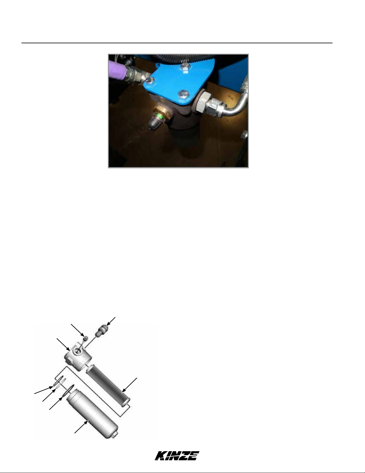
True Depth Filter
Replace filter cartridge annually, every 100 hours of operation, or when the clogging indicators point out the limit
pressure drop created inside the filter.
To replace the cartridge:
1. Stop the system in “Machine Stopped” status
2. Secure any shut-off valves on the hydraulic circuit.
3. Unscrew the filter container (1).
4. Remove the clogged filtering cartridge (5), making sure no residual particles have settled in the bowl bottom.
5. Make sure the O-ring (2-4) and the anti-extrusion ring (3) are not damaged, otherwise replace them and consequently
position the new ones correctly.
6. Insert the new filtering cartridge, lubricating the sealing O-ring beforehand.
7. Screw the container tight (1) making sure the threading is screwed correctly. Tighten to a tightening torque of 65 Nm.
8. Start the machine for a few minutes.
9. Make sure there are no leaks.
8
7
1. Filter Bowl
6
2. External O-Ring
3. Anti-extrusion ring
4. Sealing O-Ring
5. Filtering Element
6. Filter Head
5
7. By-pass valve
8. Visual differential indicator
4
3
2
1
2-12 Rev. 02/19
True Depth Cylinder
TM
Page 27
Machine Operation
Model 3660M0260-01
CONTROL CONSOLE OPERATION
Tractor’s hydraulic system and planter control console are used to raise and lower planter, rotate frame, extend and
retract tongue, lock and release wings, and operate row markers.
Contacting or coming close to power
DANGER
WARNING
lines or other high energy sources will
cause death or serious injury.
Keep away from power lines or high
energy sources at all times.
Being struck by a moving marker can
cause death or serious injury. Markers
can move unexpectedly when SCV
controls are operated. Keep marker
switch OFF when not in use.
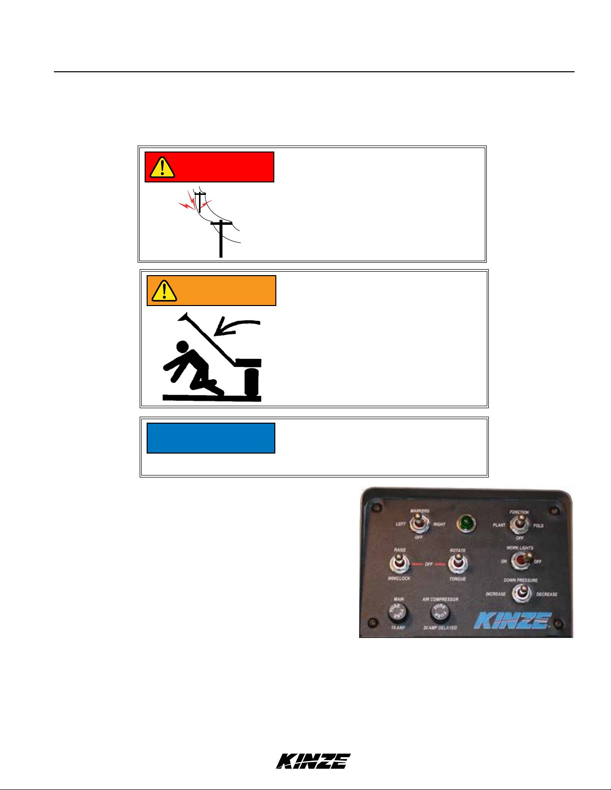
Control console face is backlit with a
NOTICE
Marker switch is an ON/OFF/ON type to select right or left
hand marker operation. It is disabled when a planter fold
function is selected. An indicator light illuminates when switch
is ON.
Raise/wing lock and rotate/tongue switches are MOMENTARY
ON/OFF/MOMENTARY ON type to select a planter fold
function. They must be held in position while operating tractor
SCV control for desired function to operate.
Down pressure switch is a MOMENTARY ON/OFF/
MOMENTARY ON type used to increase or decrease row unit
down pressure.
Work light switch is on ON/OFF type to control optional planter mounted work lights.
Point row switches are not used on Model 3660 planter. This function is controlled by Kinze Vision or Cobalt planter
controller.
power switch on back side. Turn off
console when not in use or tractor
battery will drain.
Model 3660 control box
A 50 amp main control box fuse and 20 amp delayed air compressor fuse are located on control box front lower left
face.
Rev. 02/19 2-13
TM
Page 28
Machine Operation
M0260-01Model 3660
NOTE: Hydraulic weight transfer toolbar operates when planter is in motion and hydraulic seed rate drive is
operating.
Model 3660 planters operate using three to five dual remote (SCV) hydraulic outlets:
1. Raise and lower planter during field operation with axle rockshaft (field lift).
2. In conjunction with control console switches, controls row markers, center post, wing locks, rotation, and tongue
extension.
3. Hydraulic seed rate drive.
4. Vacuum blower drive (optional).
5. Bulk fill blower drive (optional).
HYDRAULIC SEED RATE DRIVE
Refer to Ag Leader Integra or Kinze Cobalt operation manuals for information on setting and controlling hydraulic seed
rate system.
HALL EFFECT SENSOR (HYDRAULIC DRIVE ONLY)
Set Hall effect sensor within " of pick-up disc.
Hall effect sensor
HYDRAULIC WEIGHT TRANSFER TOOLBAR
The hydraulic weight transfer system is standard. The hydraulic drive system powers the hydraulic weight transfer
system. Pressure is set from the factory and does not require additional adjustment.
AG LEADER ELECTRIC CLUTCHES
Electric clutches along with GPS can stop seed flow by turning off seed meters (and planter sections) based on field
mapping and previously planted areas.
2-14 Rev. 02/19
TM
Page 29
Machine Operation
TRANSPORT TO FIELD SEQUENCE
Position planter in a relatively flat open area. Avoid an area with furrows, etc.
SUMMARIZED TRANSPORT TO FIELD SEQUENCE
1. Remove and store tongue safety pin.
2. Remove and store transport latch locking pin.
3. Remove and store safety lockup.
4. Rotate planter to field position.
5. Lower planter on center post.
6. Raise planter using field lift.
7. Release wing locks.
8. Retract tongue.
9. Lower planter to ground.
10. Remove row marker lockups.
NOTE: Read following information for detailed instructions.
Model 3660M0260-01
Snap pin
Tongue safety pin installed for transport
Tongue safety pin stored for field operation
1. With tongue fully extended, planter in transport position, and tractor shut down; remove tongue safety pin and place
it in storage position.
Transport latch locking pin
Locked transport position
Transport latch locking pin
Storage position
2. Remove transport latch locking pin from locked position and place it in storage location.
Rev. 02/19 2-15
TM
Page 30

Machine Operation
Safety lockup in storage positionSafety lockup in transport position
3. Remove safety lockup from center lift cylinder and place in storage location on hose take-up.
4. Start up tractor. Hold rotate/tongue switch
to ROTATE and operate hydraulic control to
rotate planter to field position. Transport latch will
automatically release.
M0260-01Model 3660
NOTE: Center post lift is used only for folding or
unfolding planter. Raising and lowering planter
during field operation is performed using field lift
(axle rockshaft).
5. Hold raise/wing lock switch to RAISE and operate
hydraulic control to fully lower planter on center
post.
6. Operate hydraulic control to raise planter using field lift.
7. Hold raise/wing lock switch to WING LOCK and
operate hydraulic control to release wing locks.
Planter in field lift position
Wing lock release
2-16 Rev. 02/19
TM
Page 31

Machine Operation
8. Operate hydraulic control to raise planter using
field lift.
9. Hold rotate/tongue switch to TONGUE and operate
hydraulic control to fully retract tongue. Tongue latch
automatically engages.
10. Remove row marker lockups.
Model 3660M0260-01
Field lift/tongue retraction
FIELD OPERATION
Contacting or coming close to power
DANGER
NOTICE
Raising and lowering planter is performed using field
lift (axle rockshaft) during field operation.
NOTE: Field lift cylinders are rephasing cylinders
and it is necessary to fully lower planter to rephase
them. Cylinder stops can not be used.
lines or other high energy sources will
cause death or serious injury.
Keep away from power lines or high
energy sources at all times.
Raise planter out of ground when making
sharp turns or backing up or equipment
damage may result.
Row marker lockup
Planting position
Rev. 02/19 2-17
TM
Page 32

Machine Operation
M0260-01Model 3660
PLANTING SPEED
Planters are designed to operate in a speed range of 2 to 8 mph (3.2 - 12.9 kph). Higher ground speeds generally cause
more variation in seed spacing. Speeds above 5.5 mph (8.8 kph) are typically not recommended.
FIELD TO TRANSPORT SEQUENCE
Position planter in a relatively flat area. Avoid areas with furrows, etc.
SUMMARIZED FIELD TO TRANSPORT SEQUENCE
1. Install row marker lockups.
2. Raise planter using field lift.
3. Extend tongue.
4. Engage wing locks.
5. Lower planter to ground.
6. Raise planter on center post.
7. Rotate planter to transport position.
8. Install safety lockup.
9. Install hitch safety pin.
10. Install transport latch locking pin.
NOTE: Read following information for detailed instructions.
1. Install row marker lockups.
2. Start tractor. Operate hydraulic control to raise
planter using field lift.
3. Hold rotate/tongue switch to TONGUE and operate
hydraulic control to fully extend tongue. Tongue
latch automatically engages.
Row marker lockup
Field lift/tongue extension
2-18 Rev. 02/19
TM
Page 33

Machine Operation
4. Hold raise/wing lock switch to WING LOCK and
operate hydraulic control to engage wing locks.
5. Operate hydraulic control to lower planter using
field lift.
6. Hold raise/wing lock switch to RAISE and operate
hydraulic control to fully raise planter on center
post.
7. Hold rotate/tongue switch to ROTATE and operate
hydraulic control to rotate planter to transport
position. Transport latch automatically engages.
Model 3660M0260-01
Wing lock engaged
Transport position
Rev. 02/19 2-19
TM
Page 34

Snap pin
WARNING
Machine Operation
M0260-01Model 3660
Uncontrolled movement of equipment
can cause loss of control and could
result in death, serious injury, or damage
to property and equipment. Install
all safety pins before transporting
equipment.
Tongue safety pin installed
8. Shut down tractor and remove safety lockup from storage location on hose take-up. Install safety lockup at center
post as shown. Make sure top latch is around cylinder rod and fastened with safety pin, and that lower end is
secured with detent pin.
9. Remove hitch safety pin from storage location and install in hitch.
10. Remove transport latch locking pin from storage location and install in transport latch.
Transport latch locking pin installed
2-20 Rev. 02/19
TM
Page 35

Machine Operation
TRANSPORT TO FIELD SEQUENCE USING BLUE VANTAGE
Tractor must be in neutral and allowed
NOTICE
NOTICE
WARNING
to roll freely when unfolding to prevent
equipment damage, especially in soft
conditions or when loaded with seed.
Use tractor assist as needed to aid in
unfolding and to reduce stress on frame
and transport components.
DO NOT fold or unfold planter without
planter attached to a tractor. DO NOT
unhitch planter from tractor unless fully
folded for transport or fully unfolded with
planting units lowered to ground.
Improperly operating or working on
this equipment could result in death or
serious injury. Make sure there is no one
in the area of the moving parts of the
planter.
Model 3660M0260-01
1. Remove lockups.
2. Press and hold “ROTATE TRANSPORT AXLE”. Operate proper hydraulic tractor control to lower transport axle to
field turnaround position.
3. Press and hold “LOWER WING WHEELS”. Operate proper hydraulic tractor control to lower wing wheels into
field turnaround position.
4. Press and hold “LOWER HITCH”. Operate proper hydraulic tractor control to unhook the wings.
5. Press and hold “UNFOLD”. Operate proper hydraulic tractor control to move wing out, away from tractor. Planter
is completely unfolded when stub wings are latched into the H-frame.
Note: Place tractor in reverse and slowly reverse when unfolding to prevent damage to wheel arm.
6. Lower planter and hold hydraulic lever for an additional 30 seconds to rephase lift cylinders.
7. If equipped with row markers, remove lockups and place in storage position.
8. Lower hitch to level machine during planting.
Rev. 02/19 2-21
TM
Page 36

Machine Operation
M0260-01Model 3660
VACUUM SYSTEM
Kinze vacuum seed metering system includes seed meters, seed discs, and an air system consisting of a hydraulic
driven vacuum fan which draws air through manifolds, hoses, and seed meters on each row unit.
Moving fan blades can cause amputation
WARNING
or severe injury. Never operate vacuum
fan with cover removed.
DIGITAL VACUUM READOUT
Digital vacuum readout is incorporated into in-cab display. Refer to the in-cab display operation manual for instructions.
VACUUM FAN AND BULK FILL MOTOR VALVE BLOCK ASSEMBLY
A PWM valve is incorporated into the vacuum system to control fan speed with Blue Drive equipped planters.
Refer to “Hydraulic Schematic - Vacuum Fan Motor System” on page 6-52 in Lubrication and Maintenance section.
Valve block contains a check valve that prevents vacuum fan from operating in wrong direction if pressure is applied to
return side of motor and allows fan to coast to a stop when tractor hydraulic control is returned to neutral position.
NOTE: Fan turns at a reduced speed If reverse pressure is applied.
ANALOG VACUUM OR PRESSURE GAUGE
Analog vacuum or pressure gauge connects directly to vacuum
meter (vacuum) or bulk fill (pressure) manifold and is teed into
digital sending units.
Only adjustment is to “zero” needle with no vacuum or
pressure present. If there is a significant difference between
gauge and a reading taken at meters, a different manifold
location should be found to connect hose to gauge and digital
sending unit.
KILOPASCALS
MAX PRESSURE 15 PSIG (103 KPA)
8
Analog Gauge
NOTE: Analog gauges are identical EXCEPT for plug and hose barb locations in side of gauge housing.
DO NOT connect vacuum meter or bulk fill hose to wrong gauge. Check plug and hose barb installation if
readout is erratic or appears inaccurate.
2-22 Rev. 02/19
TM
Page 37

BULK FILL SYSTEM
CAUTION
NOTICE
NOTICE
NOTICE
Machine Operation
Model 3660M0260-01
Seed flying out of disconnected delivery
tube at high velocity can cause injury.
Do not disconnect delivery tubes when
system is operating.
Foreign materials can plug system. Make
sure seed is clean and free of debris
when filling bulk fill hoppers.
Do not turn on system with tractor
engine at full speed or system damage
may occur.
Do not operate bulk fill system above
maximum system operating pressure of
20 inches of water or seed bridging may
occur.
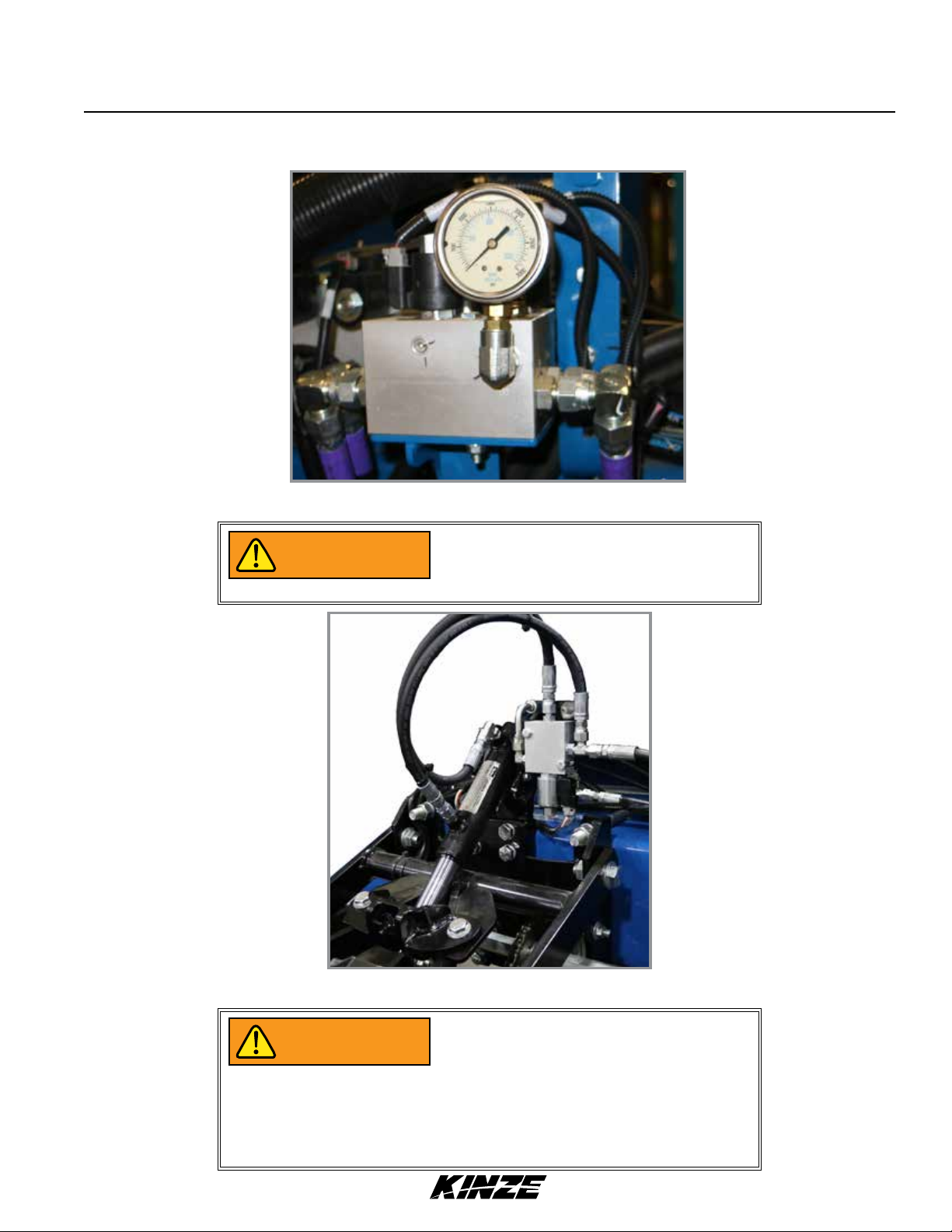
1. Before filling hoppers refer to “Transport to Field
Sequence Using Blue Vantage” on page 2-21 for
additives information. Fill hoppers with seed, latch lids,
and secure with pin.
2. Start bulk fill system with tractor engine at idle.
3. Increase engine speed to full and set initial system
pressure using flow control valve.
Note: For models equipped with True Depth hydraulic
down force tied into the bulk fill circuit, set the
tractor’s control valve (SCV) to 100%. Then use the
Flow Control Valve mounted on the RH front side
of the tool bar to set the desired bulk fill pressure.
4. Allow system to warm up and adjust pressure if necessary.
Counterclockwise
to open
Bulk Fill Lid
Flow Control Valve (True Depth)
Recommended pressures:
• Corn – 12 inches of water
• Soybeans – 10 inches of water
• Actual pressure needed is affected by seed size, shape, and coating.
Rev. 02/19 2-23
TM
Page 38

BULK FILL ENTRAINER ACCESS
Machine Operation
M0260-01Model 3660
1. Shut down bulk fill system.
2. Loosen wing nut and turn retainer holding shutoff door
in its storage location.
3. Remove rubber plug closest to area in entrainer needing
attention.
4. Insert shutoff door into open slot and push into entrainer
at a slight upward angle.
5. When work is complete, remove shutoff door, return door
to storage location, and plug open slot.
BULK FILL TANKS - CLEAN OUT
Wing nut
Rubber plug
Retainer
Shutoff door
Bulk fill entrainer (end view)
Chute hooks
Cleanout chute storage bracket
1. Remove bulk fill tank cleanout chute from storage location beneath catwalk.
2. Position tube of chute under entrainer and attach hooks on each end of entrainment assembly.
3. Open cleanout doors and empty tank.
4. Close all cleanout doors and return cleanout chute to storage location.
2-24 Rev. 02/19
TM
Cleanout chute installed
Page 39

Machine Operation
BULK FILL SCALE PACKAGE OPTION
High-pressure water can damage display.
NOTICE
NOTICE
• Provides seed weight or estimated acres remaining for each bulk fill hopper.
• Displays total (gross) seed weight or estimated acres remaining for both hoppers combined.
• Warns operator when seed goes below a pre-defined level (when using a Kinze Vision display).
Remove display before power washing
planter.
Remove and store display at end of
planting season. Damage from sun and
weather exposure may result.
Model 3660M0260-01
Operation of bulk fill Scale Package display is controlled by
buttons located on its face:
• Two screen-defined selection buttons.
• Backlight ON/OFF button.
• UP/DOWN arrow buttons.
• Screen position is changed by loosening thumb screw on
mount at back of monitor and repositioning screen.
SETUP BULK FILL SCALE PACKAGE DISPLAY
1. Press SET-UP button.
Screen defined
selection buttons
UP/DOWN arrow buttons
Backlight ON/
OFF button
2. First setup screen displays and ALARM LEVEL box is
highlighted.
3. Press SELECT button.
4. Press UP or DOWN arrows to change alarm weight level.
Select BACK to save changes.
5. Press UP or DOWN arrows to highlight WEIGHT/ACRE
MODE box. Press SELECT button.
6. Press UP or DOWN arrow buttons to toggle between
weight or acre mode. This selection affects if values are
displayed as pounds or estimated acres of seed remaining.
Press BACK to save changes.
Rev. 02/19 2-25
TM
Page 40

Machine Operation
7. Press DOWN arrow to select second set-up screen.
NOTE: CALIBRATION# and SETUP# are automatic and do
not need to be changed.
M0260-01Model 3660
8. Select
CONTRAST or BACKLIGHT. Use
UP or DOWN arrow
buttons to change levels. Press BACK to save changes.
9. Select BACK to return to main screen.
MONITOR SEED LEVELS
1. Main screen displays information for left and right hoppers.
2. Select either L or R for individual hopper status information.
3. Select BACK to return to main screen.
4. Press down arrow once or twice for GROSS screen to
appear.
This provides combined status information for both hoppers.
5. Press down arrow again to return to main screen.
ENTER SEED INFORMATION
1. Highlight and select either L (left) or R (right) for the
appropriate input screen.
2. At input screen, L or R side is indicated at left side of screen
and seed weight or acres remaining is on right side.
3. Press arrow keys to select desired box; press
SELECT to darken and use arrow keys to change.
NOTE: Seed information entered must be accurate
for remaining estimated acres to calculate correctly.
• SEEDS/ACRE is population rate.
• SEEDS/LB value comes from seed specifications.
• ZERO is selected to zero hopper that is selected.
4. Select BACK to return to main screen.
Seed weight or acres
2-26 Rev. 02/19
TM
Page 41

Machine Operation
AG LEADER INTEGRA DISPLAY
INTEGRA is a full-featured hub of any precision farming
operation. A large, full-color 12.1" HD touchscreen display
is easy to read and offers powerful, year-round precision
farming tools. Mapping, planter and application control,
yield monitoring, real-time data logging, and more – are all
controlled from the cab using the Integra display.
Four video camera inputs provide operators a better view of
equipment operation and safety by allowing them to view live
video on the display.
Model 3660M0260-01
NOTE: See Integra operator manual for installation and
programming.
AG LEADER MONITORING CONTROL (PMM)
The PMM Magnetic Distance Sensor Package includes a
planter-mounted module enclosure with cover and mounting
hardware, seed tubes w/sensors, planter harness, planter
monitor cable, shaft rotation sensors and magnetic distance
sensor components.
Ag Leader Integra display and associated cab harnesses are
also required.
AG LEADER INCOMMAND 1200 DISPLAY
The InCommand 1200 is a full-featured display for any
precision farming operation. A large, full-color 12.1" HD
touchscreen display is easy to read and offers powerful, yearround precision farming tools. Mapping, planter and application
control, yield monitoring, real-time data logging, and more –
are all controlled from the cab using the InCommand display.
Ag Leader Integra display
Planter monitor module (PMM)
Four video camera inputs provide operators a better view of
equipment operation and safety by allowing them to view live
video on the display.
Ag Leader InCommand Display
NOTE: See InCommand operator manual for installation
and programming.
Rev. 02/19 2-27
TM
Page 42

Machine Operation
M0260-01Model 3660
KINZE ISOBUS OPTION
Kinze ISOBUS option consists of a planter monitor module (PMM), and planter control module (PCM). Kinze planters
will communicate directly with most ISO compatible monitors. See the Kinze ISOBUS manual for more information.
AUXILIARY WORK LIGHTS PACKAGE
Auxiliary work lights package includes four LED lights with
brackets and hardware to mount two lights on center lift
cylinder and one on each wing. The provided wiring harness
plugs into existing planter light harness.
Lights are controlled by the work light switch on control
console.
If the planter is equipped with Blue Drive refer to M0288 - Kinze
Blue Vantage Operator’s Manual for work light control.
Auxiliary work lights
(Additional light mounted on opposite wing)
KINZE TRUE DEPTH DISPLAY
Kinze True Depth provides on demand row by row hydraulic
row unit down force ranging from 100 lbs. up force to 600
lbs. down force at 2350 psi. The system includes a 7” in cab
standalone screen display with antiglare screen protector and
RAM mount, electronic control modules, harnesses, gauge
wheel sensors, hydraulic cylinders, upper and lower cylinder
mounts, and valves.
NOTE: See True Depth Operator’s Manual for system
operation and programming.
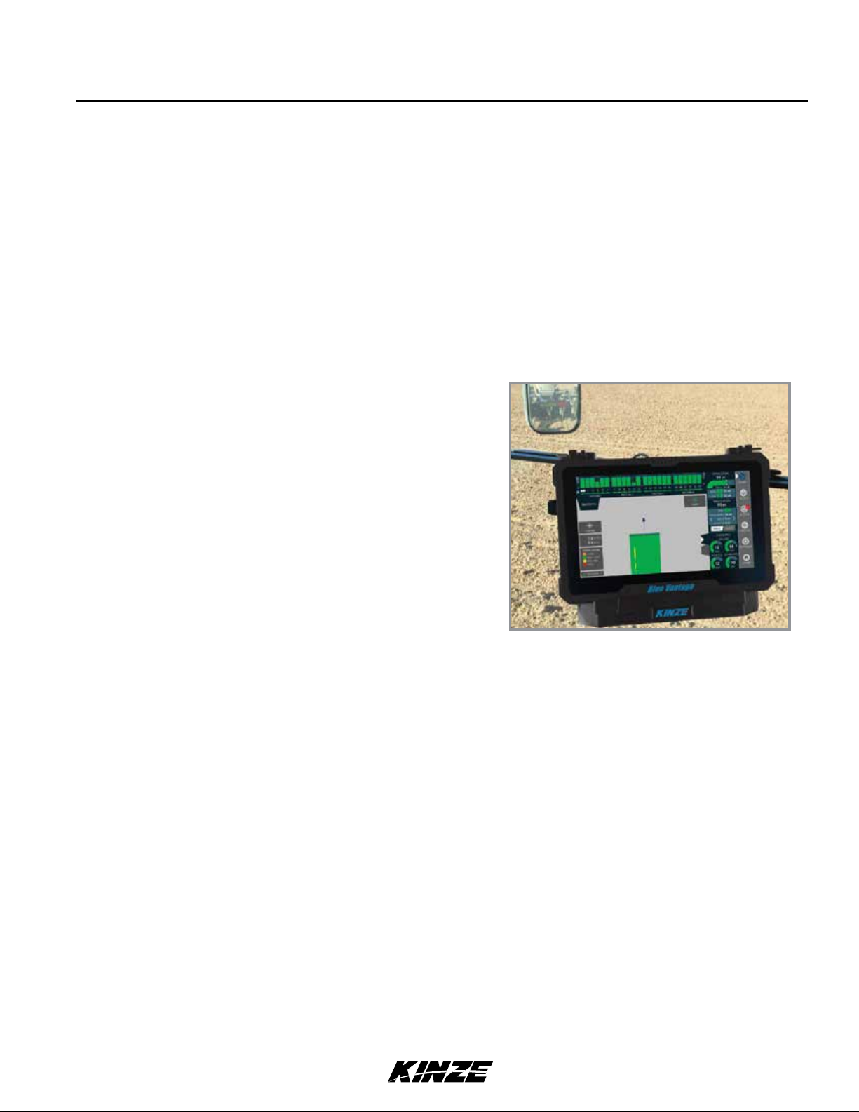
KINZE BLUE VANTAGE
Blue Vantage can be ready to plant in three taps after
proper setup. The health screen provides all critical planting
parameters and controls. The grower can observe row-by-row
planting performance in real-time.
Kinze True Depth Display
NOTE: See Kinze Blue Vantage Operator’s Manual for
system operation and programming.
Kinze Blue Vantage
2-28 Rev. 02/19
TM
Page 43

ROW MARKER OPERATION
DANGER
Machine Operation
Model 3660M0260-01
Contacting or coming close to power
lines or other high energy sources will
cause death or serious injury.
Keep away from power lines or high
energy sources at all times.
Marker switch
Two solenoid valves on valve block at rear R.H. side of center frame, and a three position selector switch on control
console permit operator to lower or raise desired row marker.
Marker position switch must be OFF
NOTICE
See “Row Marker Speed Adjustment” on page 2-30.
If the planter is equipped with Blue Drive refer to M0288 - Kinze Blue Vantage Operator’s Manual for marker control.
1. Select which row marker to lower on control console.
2. Operate hydraulic control to lower row marker.
3. Move control switch to other side to operate opposite row marker.
4. Raise row marker at end of field using hydraulic control.
5. After turn, using the hydraulic control, lower the pre-selected row marker.
6. Continue to follow this procedure.
NOTE: Both row markers can be lowered by operating switch in each position and hydraulic control twice.
Row markers raise simultaneously with hydraulic control in raise position.
when planter is not in use or tractor
battery will drain.
Row marker solenoid valves
If electrical system does not operate properly:
• Check fuse.
• Check wiring connections.
• Check control switch.
• Check solenoid. SOLENOID HOUSING IS MAGNETIZED WHEN ENERGIZED.
Rev. 02/19 2-29
TM
Page 44

Machine Operation
ROW MARKER SPEED ADJUSTMENT
Excessive row marker travel speed
NOTICE
Marker hydraulic system includes two flow control valves. One
flow control valve sets lowering speed and one sets raising
speed of both markers. Flow controls determine amount of oil
flow restriction through valves, varying marker travel speed.
Loosen jam nut and turn control clockwise, or IN to slow travel
speed. Turn counterclockwise, or OUT to increase travel speed.
Tighten jam nut after adjustments are complete.
NOTE: Tractors with flow control valves. Make row marker
speed adjustment with tractor flow controls in maximum
position. After row marker speed is set, adjust tractor flow
controls to allow hydraulic control to stay in detent during
marker raise or lower cycle.
can damage row markers. Adjust flow
controls before row markers are first
used.
M0260-01Model 3660
Row marker speed control adjustment
NOTE: Hydraulics operate slowly when oil is cold. Make all adjustments with oil warm.
NOTE: On a tractor where oil flow cannot be controlled, tractor flow rate may be greater than rate marker
cylinder can accept. Hold tractor hydraulic control lever until cylinder reaches end of its stroke. This occurs
most often on tractors with an open center hydraulic system.
EVEN-ROW PUSH ROW UNIT
An Even-Row Push Row Unit Package is available to add one
additional push row unit on outer L.H. side of front toolbar for
use with Solid Row Interplant Package.
NOTE: See “Row Marker Adjustments” on page 2-31 for
determining correct length to set row marker assemblies
when planting with even-row push row unit option.
An inner hitch with a 7½" offset mount is available from Kinze
through your Kinze Dealer to plant two 15" rows between last
year’s 30" rows and avoid tire damage from stalks by driving off
row
Even-row push row unit
NOTE: install hitch onto 2-point hitch bar using R.H. hole
If 2-Point Hitch Option is used. A 7½" offset mount is
not needed. See “Offset Hitch Adjustment” for additional
information.
2-30 Rev. 02/19
TM
Page 45

Machine Operation
ROW MARKER ADJUSTMENTS
1. Multiply number of rows by the average row spacing in inches to determine total planting width.
Model 3660M0260-01
Row Marker Lengths
12 Row 30" 360" (914.4 cm)
16 Row 30" 480" (1219.2 cm)
2. Lower planter and row marker assembly to ground.
3. Measure from planter center line to a point where blade contacts ground.
4. Adjust row marker extension so distance from marker disc blade to center line of planter is equal to total planting
width. Adjust right and left row marker assemblies equally and securely tighten clamping bolts.
Loosen hardware to
Loosen hardware to
adjust marker length.
adjust blade angle.
Depth band
Concave side faces
towards planter.
Row marker disc blade angle adjustment
Setting marker disc blade assembly at a
NOTICE
sharper angle than needed adds stress
to row marker assembly and shortens
bearing and blade life. Set blade angle
only as needed to leave a clear mark.
Marker disc blade is installed with concave side facing inward. Spindle assembly is slotted so hub and blade can be
angled to throw more or less dirt.
5. Loosen hardware and move assembly as required.
6. Tighten bolts to specified torque.
7. Do a field test to ensure markers are properly adjusted.
NOTE: A notched marker blade is available from Kinze through your Kinze Dealer for use in more severe no
till conditions.
Rev. 02/19 2-31
TM
Page 46

Machine Operation
ROW MARKER EVEN-ROW LENGTH ADJUSTMENT
Adjust marker extensions as shown below when using even-row push row unit option.
Planter centerline To center of outer row unitTo center of outer row unit
M0260-01Model 3660
Center Of 15" Dimension
Planter To x 2 + Row = Between
Center Of Spacing Planter Center
NOTE: Readjust row markers when planting
30" rows.
Outer Row Line And
Unit Marker Blade
Number Of Rows x Row Spacing (Inches)
12 Row 30" With 12 Interplant Push Row Units
(L.H. Marker 180" x 2 + 15" = 375")
(R.H. Marker 165" x 2 + 15" = 345")
Dimension Between Planter Center Line
16 Row 30" With 16 Interplant Push Row Units
(L.H. Marker 240" x 2 + 15" = 495")
(R.H. Marker 225" x 2 + 15" = 465")
12 Rows x 30" Spacing = 360" Marker Dimension
16 Rows x 30" Spacing = 480" Marker Dimension
OFFSET HITCH ADJUSTMENT
An offset hitch is available from Kinze through your Kinze Dealer. Offset hitch
provides centered and offset mounting positions for hitch clevis.
If tractor hitch is offset 7½" right of tractor center line, add 7½" to marker
dimension on R.H. side of planter and subtract 7½" from marker dimension
on L.H. side of planter.
=
And Marker Blade
Tractor center line
Tractor hitch offset
7½" right.
2-32 Rev. 02/19
TM
Page 47

POINT ROW CLUTCHES
Machine Operation
Model 3660M0260-01
Output hub
Stop collar
Wrap spring
Input hub
Control tang
Point row clutch
Electric-activated clutches disengage drive on either half of planter for finishing up fields or for long point row
situations. Clutch selector switch is located on tractor control box.
NOTE: Liquid fertilizer piston pump has its own drive wheel and is not affected by point row clutch.
Clutch consists of a wrap spring riding on an input and output hub. Wrap spring is wrapped tightly over hubs during
operation locking them together. Higher speeds create a tighter grip of spring on hubs.
Input end of spring is bent outward and is called the control tang. Control tang fits into a slot in stop collar located
between input and output hubs over wrap spring. If stop collar is allowed to rotate with input hub, clutch is engaged. If
stop collar is stopped from rotating, control tang connected to it is forced back and spring opens. This allows input hub
to continue rotating without transmitting torque to output hub, stopping planter drive.
Stop collar is controlled by an electric solenoid and an actuator arm. When selector switch on tractor control box is
OFF, solenoid coil is NOT ENERGIZED and actuator arm will not contact stop on stop collar, allowing it to rotate with
hubs and drive planter.
When “DISENGAGED” solenoid coil IS ENERGIZED and plunger in solenoid coil pulls actuator arm against stop on
stop collar, disengaging wrap spring and stopping planter drive.
Rev. 02/19 2-33
TM
Page 48

Machine Operation
M0260-01Model 3660
AUXILIARY HYDRAULIC OPTION
A customer-supplied auxiliary hydraulic option may be added to provide 10 gpm of oil flow at rear of planter. It is
designed for powering bulk seed handling equipment when planter is not in motion and is controlled by the same
tractor hydraulic control as the seed rate hydraulic drive.
Pressurized hydraulic fluid can penetrate
WARNING
body tissue and result in death, serious
infection, or other injuries. Fluid injected
under skin must be IMMEDIATELY
removed by a surgeon familiar with this
type of injury. Make sure connections
are tight and hoses and fittings are
not damaged before applying system
pressure. Leaks can be invisible. Keep
away from suspected leaks. Relieve
pressure before searching for leaks or
performing any system maintenance.
Make sure MASTER switch is OFF on
NOTICE
AUX2
Customer-supplied hoses, fittings, and hydraulic outlets are added to ports AUX1 and AUX2 on lower valve block on
back side of planter. Refer to “Hydraulic System Schematics” in the Lubrication and Maintenance section for additional
information.
Kinze Vision or Cobalt display and
planter is not in motion when using
auxiliary hydraulic circuit.
AUX1
Lower valve block
2-34 Rev. 02/19
TM
Page 49

Machine Operation
REAR TRAILER HITCH
Rear trailer hitch can tow a 3 or 4 wheel wagon behind planter.
A spring, chain, and mounting bracket supports a 1¼" feed hose
from hitch to piston pump. This extra length or loop is required
to allow for planter to move into transport position without
stretching hose.
Rear trailer hitch is designed for use
NOTICE
with piston pump only. Maximum
allowable hitch weight is 200 lb (90.71
kg). Do not exceed 6,000 lb (2,721.55 kg)
gross towing weight or the equivalent
of a loaded 500 gal (1,892.7 L) tank
and running gear or equipment can be
damaged.
Model 3660M0260-01
Trailer hitch
NOTE: Periodically check feed hose for kinks to prevent restricted delivery rate.
50"
Minimum Clearance
91" 12 Row 30"
151" 16 Row 30"
NOTE: Minimum
hitch length required
to rotate planter into
transport position.
500
Gallon
Tank
Rev. 02/19 2-35
TM
Page 50

Machine Operation
M0260-01Model 3660
FIELD TEST
Perform a field test with any change of field and/or planting conditions, seed size or planter adjustment to ensure
proper seed placement and operation of row units.
Check planter for front to rear and lateral level operation. See “Level Planter”.
Check all row units to be cer tain they are r unning level. Row unit parallel arms should be approximately parallel to
the ground when planting.
Check row markers for proper operation and adjustment. See “Row Marker Adjustment” and “Row Marker Speed
Adjustment”.
Check for proper application rates and placement of granular chemicals on all rows. See “Field Check Granular
Chemical Application”.
Check for desired depth placement and seed population on all rows. See “Field Check Seed Population”.
Check for proper application rates of fertilizer on all rows. See “Fertilizer Application Rate Chart”.
Reinspect machine after field testing.
Hoses And Fittings
Bolts And Nuts
Cotter Pins And Spring Pins
Drive Chain Alignment
FIELD CHECK SEED POPULATION
1. Tie up one or more sets of closing wheels by running
a chain or rubber tarp strap between the hopper support
panel and closing wheels. It may be necessary to decrease
closing wheel arm spring tension.
Planting depth
adjustment handle
Chain, rubber tarp
strap, or similar.
2. Plant a short distance and check to see if seed is
visible in the seed trench. Adjust planting depth to a
shallower setting if seed is not visible and recheck.
Deeper Shallower
Planting depth adjustment
2-36 Rev. 02/19
TM
Page 51

Machine Operation
Model 3660M0260-01
3. Measure of an acre. See chart for correct distance for row width being planted. For example, if planting 30"
rows of an acre would be 17' 5".
Acre Seed Population Count Row Width/Distance
Row Width 15" 18" 19" 30" 36" 38"
Distance 34'10" 29'0" 27'8" 17'5" 14'6" 13'10"
NOTE: Seeds may bounce or roll when planting with closing wheels raised and planting depth set shallow
affecting seed spacing accuracy.
4. Count seeds in measured distance.
5. Multiply number of seeds placed in of an acre by 1000. This gives total population.
Seed count can be affected by drive wheel and seed meter drive ratio, tire pressure, and/or seed meter malfunction.
1. If seed check shows average distance between seeds in inches is significantly different than seed rate chart
indicates, first check drive ratio between drive wheel and seed meter. Check drive wheel air pressure, check for
incorrect sprocket(s) in driveline and check drive and driven sprockets on transmission(s) for proper selection.
2. Check for seed meter malfunction. For example, if spacing between kernels of corn at the transmission setting
being used is 8" and a gap of 16" is observed, a finger has lost its seed and not functioned properly. If two seeds
are found within a short distance of each other, finger has metered two seeds instead of one.
3. See “Seed Meter (Finger Pickup)” on page 7-8 or “Seed Meter (Brush-Type)” on page 7-5 in Troubleshooting
Section of this manual.
EXAMPLE: 30" row spacing 17' 5" equals acre.
26 seeds counted x 1000 = 26,000 seeds per acre
DETERMINING POUNDS PER ACRE (BRUSH-TYPE METER)
Seeds per acre ÷ Seeds per pound (from label) = Pounds per acre
If seeds per pound information is not available use the following averages:
2,600 seeds per pound for medium size soybeans
15,000 seeds per pound for medium size milo/grain sorghum
4,500 seeds per pound for medium size cotton
DETERMINING BUSHELS PER ACRE
Pounds per acre ÷ Seed unit weight = Bushels per acre
Average Unit Weight of:
1 Bushel Soybeans = 60 Pounds
1 Bushel Milo/Grain Sorghum = 56 Pounds
1 Bushel Cotton = 32 Pounds
If seed population check shows planting rate is significantly different than seed rate chart shows or if a particular meter
is not planting accurately, see “Brush-Type Seed Meter Maintenance” and “Seed Meter (Brush-Type) Troubleshooting”.
Rev. 02/19 2-37
TM
Page 52

Machine Operation
M0260-01Model 3660
FIELD CHECK GRANULAR CHEMICAL APPLICATION
Temperature, humidity, speed, ground conditions, flowability of different material, or meter obstructions can affect
granular chemical rate of delivery.
Agricultural chemicals can cause death
WARNING
Perform a field check to determine application rates.
or serious injury to persons, animals,
and plants or seriously damage soil,
equipment, or property. Read and
follow all chemical and equipment
manufacturers labels and instructions.
Calibrated vial
Granular chemical field check
1. Fill insecticide and/or herbicide hoppers.
2. Attach a calibrated vial to each granular chemical meter.
NOTE: Disengage clutch to avoid dropping seed during test.
3. Lower planter and drive 1320 feet at planting speed.
4. Weigh chemical in ounces caught in one vial.
5. Multiply that amount by factor shown to determine pounds per acre.
Pounds Per Acre
Row Width Factor
30" .83
36" .69
38" .65
EXAMPLE: You are planting 30" rows. You have planted for 1320 feet at desired planting speed. You caught 12.0
ounces of chemical in one vial. 12.0 ounces times 0.83 equals 9.96 pounds per acre.
NOTE: Check calibration of all rows.
METERING GATE
Use metering gate setting as a starting point for distributing insecticide or herbicide. Charts are based on 5 mph
(8 kph) planting speed. Use a higher gate setting for speeds faster than 5 mph (8 kph) and a lower setting for speeds
slower than 5 mph (8 kph).
2-38 Rev. 02/19
TM
Page 53

Row Unit Operation
Model 3660M0260-01
PLANTING DEPTH
Planting
Planting depth is maintained by adjustable row unit gauge
wheels. Depth adjustment range is approximately ½" to 3½".
depth
adjustment
handle
1. Raise planter to remove weight from wheels.
2. Push down on depth adjustment handle and reposition
it forward to decrease or rearward to increase planting
depth. Initially adjust all units to the same setting.
3. Lower planter and check operation and planting depth
of all row units. Readjust individual rows as needed for
uniform operation.
Planting depth adjustment
“V” CLOSING WHEEL ADJUSTMENT (RUBBER OR CAST IRON)
Eccentric bushing
Down pressure
adjustment lever
Set closing wheels in
forward hole for directly
opposite installation.
Deeper Shallower
Decrease
Increase
Eccentric
bushing
“V” Closing wheel adjustments
“V” closing wheels should have enough down pressure to close the seed trench and ensure good soil to seed contact.
Move 5-position quick adjustable down force lever on the top of closing wheel arm to the rear to increase closing
wheel spring pressure. Move lever forward to decrease pressure. Adjust all row units to a similar setting. Light soil
usually requires less down force at average depth (approximately 2") while heavy soil requires increased down force.
Eccentric bushings in the wheel arm stop allow for lateral adjustment of the “V” closing wheel assembly. Use a ¾"
wrench to loosen hardware attaching closing wheel arm to wheel arm stop. Use another ¾" wrench to turn eccentric
bushings until closing wheels are aligned with seed trench. Tighten hardware.
Closing wheels can be installed “offset” (to improve residue flow) or “directly” opposite. Use forward installation holes If
set “directly” opposite.
CLOSING WHEEL SHIELD (RUBBER OR CAST IRON “V” CLOSING WHEELS)
Optional closing wheel shield is installed on underside of
closing wheel arm to help prevent root balls and stalks from
clogging closing wheels.
Closing wheel shield (Closing wheel removed)
Rev. 7/19 3-1
TM
Page 54

Row Unit Operation
DRAG CLOSING ATTACHMENT
Drag closing attachment pulls loose soil over seed trench.
M0260-01Model 3660
NOTE: Use of a seed firming wheel or other seed firming
device is recommended with drag closing attachment.
Front and rear adjustment is made using slotted holes in
blades. Adjust all rows the same. Wheel arm stop eccentric
bushings provide lateral adjustment. Use a ¾" wrench to
Adjustment slots
loosen closing wheel arm to wheel arm stop hardware. Use
another ¾" wrench to turn eccentric bushings until drag closing
attachment is aligned with seed trench. Tighten hardware.
COVERING DISCS/SINGLE PRESS WHEEL ADJUSTMENT
Press wheel down force adjustment
Eccentric
bushing
Blade
Drag closing attachment
Adjusting bolt
2½"
Tab
½" Locking nut
Check operation of covering discs/single press wheels after adjusting planting depth. Initial press wheel down force
spring setting is 2½" between mounting arm tab and locking nut. Loosen ½" locking nut and turn adjusting bolt in to
increase down force or out to decrease down force. Tighten locking nut against spring plug. Adjust all row units to a
similar setting.
Locate for staggered or
side-by-side operation
Blade depth
adjustment
Eccentric
bushing
Blade angle
adjustment
Wheel arm stop
Covering disc adjustments
Eccentric bushings in the wheel arm stop allow for lateral adjustment of covering discs/single press wheel assembly.
Use a ¾" wrench to loosen hardware attaching closing wheel arm to wheel arm stop. Use another ¾" wrench to turn
eccentric bushings until covering discs/single press wheel assembly is aligned with seed trench. Tighten hardware. Two
sets of holes in mounting arm locate covering discs for staggered or side-by-side operation. Five sets of holes in each
disc bracket allow ½" incremental blade depth adjustment. Slotted holes in disc mount and bracket allow for 0° - 15°
blade angle adjustment. Adjust covering discs on all row units to similar settings.
3-2 Rev. 7/19
TM
Page 55

Row Unit Operation
SEED HOPPERS
Mechanical seed hopper has a capacity of 1.9 bushels.
Vacuum seed hopper has a capacity of 1.75 bushels.
Use clean seed and make certain there are no foreign objects
inside when filling seed hopper. Replace hopper lids after
hoppers are filled to prevent accumulation of dust or
dirt in seed meter which can cause premature wear. See
“Finger Pickup Seed Meter” and/or “Brush-Type Seed Meter”.
Model 3660M0260-01
Periodically empty hoppers completely to remove any foreign
objects and to ensure proper seed meter operation.
Disengage meter drive and hopper latch and lift hopper off hopper support. See “Seed Meter Drive Release”.
Seed hopper is retained by an over-
DANGER
center latch. Wear gloves to prevent
injury to hands while releasing the latch.
Mechanical seed hopper
SEED METER DRIVE RELEASE
A clutch release mechanism disengages seed meter drive
from seed meter to remove seed hopper or prevent meter from
operatiing. Releasing drive allows operator to check granular
chemical application rates without dropping seed. It also allows
one or more rows to be disconnected when finishing fields.
Turn knob ¼ turn counterclockwise to release or ¼ turn
clockwise to engage drive.
Release
Drive
Seed meter drive release
ROW UNIT EXTENSION BRACKETS
Row unit extension brackets extend row units rearward 4" to
provide clearance for coulter mounted residue wheels and HD
single disc fertilizer openers.
Extension
bracket
Row unit extension brackets
Rev. 7/19 3-3
TM
Extension
bracket
Page 56

Row Unit Operation
ROW UNIT CHAIN ROUTING
Row unit drive chains must be properly tensioned and aligned for proper operation and to minimize wear.
Inspect and replace weak, worn or broken springs, idlers, and idler bushings.
M0260-01Model 3660
Mechanical pull row unit meter drive
Mechanical push row unit meter drive
Vacuum pull row unit meter drive
Vacuum push row unit meter drive
Direction of travel
Closed end
NOTE: Install connector link with
closed end facing direction of travel.
Row unit granular chemical drive
NOTE: Reverse idler when worn on
one side for extended use.
3-4 Rev. 7/19
TM
Page 57

Row Unit Operation
Model 3660M0260-01
QUICK ADJUSTABLE DOWN FORCE SPRINGS OPTION (STANDARD OR HEAVY DUTY)
Standard and heavy duty quick adjustable down force springs are available in increase penetration in hard soil and
keep row unit from bouncing in rough field conditions. Two springs per row, one on each side parallel arms, are used
unless equipped with row unit mounted no till coulters. Row unit mounted no till coulters require four springs per row.
Two springs per row (Dual)
Pin
Pin
Position 2 Position 3Position 1 (Least) Position 4 (Most)
There are four positions to set down pressure spring tension.
Standard and Heavy Duty Spring Down Force Pressure*
2 Springs 4 Springs
Position
1 41lb (18.6 kg) 43 lb (19.5 kg) 74 lb (33.6 kg) 80 lb (36.3 kg)
2 73 lb (33.1 kg) 86 lb (39.0 kg) 120 lb (54.4 kg) 144 lb (65.3 kg)
3 136 lb (61.7 kg) 167 lb (75.7 kg) 255 lb (115.7 kg) 307 lb (139.3 kg)
4 207 lb (93.9 kg) 249 lb (113.0 kg) 369 lb (167.4 kg) 470 lb (213.2 kg)
*Pressure does not include weight of row unit, seed, or options.
Standard
D8249
Heavy Duty
D21337
Pin
Four springs per row (Quad)
Pin
Standard
D8249
Heavy Duty
D21337
Springs must be installed with open side
NOTICE
of spring hooks toward seed hoppers
to prevent binding on spring mount
adjustment pins.
1. Raise planter and remove spring mount pin at top of spring.
2. Slide mount to desired position and install pin.
NOTE: Adjust springs for field conditions. Too much down pressure in hard field conditions can cause
row units to lift planter and keep drive wheels from making contact. Too much down pressure in soft field
conditions can cause row unit to run too deep.
Rev. 7/19 3-5
TM
Page 58

Row Unit Operation
M0260-01Model 3660
PNEUMATIC DOWN PRESSURE PACKAGE OPTION
Row unit down pressure can be adjusted on-the-go as field conditions change with pneumatic down pressure option.
A cab-mounted control box adjusts pressure (Older models may have a digital readout). A planter-mounted 12 VDC
air compressor with 3 gallon capacity air tank supplies air for the down pressure system.
Packages include upper and lower air spring mounting castings for pull row units (front and rear air spring mounting
castings for push row units), 150 psi rated air springs, " O.D. nylon hoses, dual solenoid air valve and stainless steel,
160 psi, 2" liquid-filled gauge and planter wiring harness.
Pneumatic down pressure row unit extension brackets are required in some applications.
Pull row unit air spring
Push row unit air spring
NOTE: Assist springs are available through your Kinze dealer if additional down pressure is needed. One
spring is installed on outer side of parallel arms on each side of row unit as shown below.
Pull row unit assist springs
Push row unit assist springs
3-6 Rev. 7/19
TM
Page 59

Row Unit Operation
Model 3660M0260-01
FIELD OPERATION
NOTE: Adjust down pressure with planter lowered and row openers in ground for most accurate adjustment.
Pressure can be adjusted from tractor using control console, or at planter using manual control valves on
compressor assembly.
Pressure gauge
Control console
Shutoff valve
Decrease
pressure
Air compressor assembly controls
Increase
pressure
ADJUST DOWN PRESSURE FROM CAB
Push toggle switch left to increase or right to decrease pressure.
ADJUST DOWN PRESSURE AT PLANTER
Push and hold decrease or increase button on compressor assembly to decrease or increase pressure.
NOTE: Value on the air pressure gauge is NOT down pressure force. Multiply air pressure (psi) by four (4) to
calculate down pressure.
LOCK UP PUSH ROW UNITS EQUIPPED WITH PNEUMATIC DOWN PRESSURE SPRINGS
1. Disconnect electric power supply to compressor.
2. Press and hold button on solenoid until pressure gauge reads zero.
3. Lock up units. See “Interplant Push Unit Lockup” for instructions.
4. Turn shutoff valve handle perpendicular to valve body to turn off air supply to push row units.
NOTE: If control console is ON and pneumatic down force is not set to zero, compressor will start when
electric power supply is reconnected.
5. Reconnect electric power supply to compressor.
Refer to M0288 - Kinze Blue Vantage Operator’s Manual for pressure adjustment with Blue Vantage.
Rev. 7/19 3-7
TM
Page 60

Row Unit Operation
M0260-01Model 3660
TRUE DEPTH OPTION
True Depth provides on demand row by row hydraulic row unit down force ranging from 100 lbs. up force to 600 lbs.
down force at 2350 psi. The system includes a 7" in cab standalone touchscreen display with antiglare screen
protector and RAM mount, electronic control modules, harnesses, gauge wheel sensors, hydraulic cylinders, upper
and lower cylinder mounts, and valves. See M0286 - Kinze True Depth Operator’s Manual.
True Depth
3-8 Rev. 7/19
TM
Page 61

Row Unit Operation
Model 3660M0260-01
TRUE DEPTH CONSOLE INSTALLATION
TRACTOR REQUIREMENTS
Consult your dealer for information on horsepower, hydraulic and electrical requirements, and tractor compatibility.
Requirements vary with planter options, tillage, and terrain.
TRACTOR INSTALLATION
Refer to Kinze Instruction Sheet IS1028 for installation of the True Depth down force system.
True Depth Console
Rev. 7/19 3-9
TM
Page 62

Row Unit Operation
M0260-01Model 3660
TRUE DEPTH HARNESS INSTALLATION
Connect tractor power harness terminal E1 to positive battery terminal. Connect terminal E2 to negative battery
terminal. Connect console harness P4 to display C1, and console harness P5 to display C2. Connect console
harness P3 to the speaker box. Connect console harness P1 to tractor power harness J2. Connect the intermediate
harness P1 to the tractor power harness J1.
DANGER
Bluetooth
Dongle
ELECTRICAL SHOCK HAZARD
Disconnect (unplug) power
before installing, inspecting, or
servicing the unit.
SPEAKER
CONNECTOR
Planter
Connector
Intermediate
Harness
HARNESS
CONNECTORS
P1
J1
C2
C1
P6
P4
DISPLAY
CONNECTORS
P5
P3
Convenience
Plug
Console
Harness
P1
J2
Tractor
Power
Harness
E1
BATTERY
CONNECTORS
E2
True Depth Harness Installation
3-10 Rev. 7/19
TM
Page 63

Row Unit Operation
INTERPLANT PUSH ROW UNIT LOCKUPS
Push row unit lockups lock interplant row units in a raised position.
Improper lifting of row units can cause
CAUTION
serious injury. An empty row unit
requires minimum 90 lb (40.8 kg) lift.
Set down pressure springs to minimum,
lower planter to ground, and empty seed
hopper before attempting to lift with this
lever.
Model 3660M0260-01
Lift lever positioned on push row unit
Lockup released for field operation
Lift lever in storage location
Push row unit locked in raised position
Rev. 7/19 3-11
TM
Page 64

Row Unit Operation
M0260-01Model 3660
To Lock Row Unit in Raised Position:
1. Set row unit down pressure springs to minimum setting.
2. Lower the planter to the planting position.
3. Empty seed hoppers.
Note: If planter is equipped with True Depth, enable Lift Assist Mode with the True Depth Display.
See M0286 - Kinze True Depth Manual, Page 18.
Turning Lift Assist on or off may cause
WARNING
4. On each push row unit lockup, flip the spring tab forward.
the planter to move or row units to fall
causing injury or death.
Uncontrolled movement of equipment
DANGER
5. Using the lift lever, raise the push row unit to allow the
spring loaded lockups to snap into locked position under
the row unit stops.
6. Ensure that the row unit is lowered onto the stops.
can cause loss of control and could
result in death, serious injury, or damage
to property and equipment. Keep clear of
row unit while lowering it to the ground.
7. Repeat Steps 4 through 6 on remaining push row units.
3-12 Rev. 7/19
TM
Page 65

Row Unit Operation
Model 3660M0260-01
To Release Row Unit to Planting Position:
1. Lower the planter to the planting position.
Note: If planter is equipped with True Depth, enable Lift Assist Mode with the True Depth Display.
See M0286 - Kinze True Depth Manual, Page 18.
Turning Lift Assist on or off may cause
WARNING
2. On each push row unit lockup, flip the spring tab rearward.
the planter to move or row units to fall
causing injury or death. Please ensure
that all row units are pushed down before
exiting Lift Assist mode.
Uncontrolled movement of equipment
DANGER
3. Using the lift lever, raise the push row unit to allow the spring
loaded lockups to snap out of locked position. Lower row
unit to the ground.
4. Ensure that the row unit is lowered all the way to the ground.
5. Repeat Steps 2 and 4 on remaining push row units.
can cause loss of control and could
result in death, serious injury, or damage
to property and equipment. Keep clear of
row unit while lowering it to the ground.
Rev. 7/19 3-13
TM
Page 66

BRUSH-TYPE SEED METER
Crop
Soybean Black
Row Unit Operation
Upper
Disc Color-Code
(Disc Part No.)
(GA5794)
Brush
Retainer Cells
GD11122 60 2200 to 4000
M0260-01Model 3660
Seed Size
Range *Lubricant
Graphite
seeds/lb.
Talc
Specialty Soybean Dark Blue
(GA6184)
Small Milo/Grain Sorghum Red
(GA5982)
Large Milo Grain Sorghum Light Blue
(GA6187)
High-Rate Small Milo/Grain Sorghum
High-Rate Large Milo/Grain Sorghum
Cotton, Acid-Delinted White
Red
(GA5795)
Yellow
(GA6633)
(GA5796)
GD11122 48 1400 to 2200
seeds/lb.
GD8237 30 14,000 to
20,000
seeds/lb.
GD8237 30 10,000 to
16,000
seeds/lb.
GD8237 60 12,000 to
18,000
seeds/lb.
GD8237 60 10,000 to
14,000
seeds/lb.
GD11122 30 4200 to 5200
seeds/lb.
Graphite
Talc
Talc
Talc
Talc
Talc
Talc
Large Cotton, Acid Delinted Ta n
(GA6168)
High-Rate Cotton, Acid-Delinted Light Green
(GA6478)
Hill-Drop Cotton, Acid-Delinted Brown
(GA6182)
Small Hill-Drop Cotton, AcidDelinted
*For More information on application rate see Additives section.
Use GD11122 upper brush retainer
when using cotton and soybean discs.
Dark Green
(GA7255)
3-14 Rev. 7/19
GD11122 36 3800 to 4400
seeds/lb.
GD11122 48 4200 to 5200
seeds/lb.
GD11122
GD11122 12
TM
12
4000 to 5200
(3 to 6
seeds/
cell)
(3 to 6
seeds/
cell)
Use GD8237 upper brush retainer when
using milo/grain sorghum discs.
seeds/lb.
5000 to 6200
seeds/lb.
Talc
Talc
Talc
Talc
Page 67

BRUSH-TYPE SEED METER 2.0
Crop
Soybean Black
Row Unit Operation
Upper
Disc Color-Code
(Disc Part No.)
(GB1123)
Brush
Retainer Cells
GB1084 60 2200 to 4000
Model 3660M0260-01
Seed Size
Range *Lubricant
Graphite
seeds/lb.
Talc
Soybean Dark Gray
(GB1171)
Specialty Soybean Dark Blue
(GB1124)
Small Milo/Grain Sorghum Orange
(GB1130)
Large Milo Grain Sorghum Light Blue
(GB1131)
High-Rate Small Milo/Grain Sorghum
High-Rate Large Milo/Grain Sorghum
Wheat Purple
*For More information on application rate see Additives section.
Use GB1084 upper brush retainer when
using wheat and soybean discs.
Red
(GB1132)
Yellow
(GB1133)
(GB1134)
GB1084 54 2000 to 3000
seeds/lb.
GB1084 48 1400 to 2200
seeds/lb.
GB1107 30 14,000 to
20,000
seeds/lb.
GB1107 30 10,000 to
16,000
seeds/lb.
GB1107 60 12,000 to
18,000
seeds/lb.
GD8237 60 10,000 to
14,000
seeds/lb.
GB1084 54 N/A
Volumetric
Use GB1107 milo insert when using milo/
grain sorghum discs.
Graphite
Talc
Graphite
Talc
Talc
Talc
Talc
Talc
Graphite
Talc
Rev. 7/19 3-15
TM
Page 68

Row Unit Operation
M0260-01Model 3660
Turn seed disc counterclockwise when installing on meter hub while
tightening two wing nuts that retain disc. Seed disc should have slight
resistance when rotated counterclockwise after wing nuts are tight.
Brush-type seed meter attaches to seed hopper same as finger
pickup seed meter. Secure to bottom of seed hopper with two "
thumbscrews. Tighten thumbscrews slightly with pliers. DO NOT
OVER TIGHTEN.
Misalignment between drive coupler and seed meter input shaft may
cause erratic seed spacing from momentary stoppage of seed disc.
Check alignment and adjust as needed.
Refer to planting rate charts in this manual for recommended seed
drive transmission sprocket combinations.
Shown without seed disc installed
Replace hopper lids after hoppers are filled
NOTICE
NOTE: Clean seed is required to ensure accurate seed metering from brush-type seed meters. Remove seed discs
daily and check seed meter or brushes for buildup of foreign material, such as hulls, stems, etc.
to prevent accumulation of dust or dirt in
seed meter which will cause premature
wear.
FINGER PICKUP SEED METER
Crop
Corn
No. 1 and/or No. 2 size
Confectionery Sunflower Seeds
No. 3 and/or No. 4 size
Oil Sunflower Seeds
Fingers
Part No.: GR1848 Finger Assembly, Corn
Part No.: GR1848 Finger Assembly, Corn
Part No.: GR2154 Finger Assembly, Oil
*Lubricant
Graphite
Talc
Talc
Talc
Blank fingers replace alternate fingers to reduce planting
rate by half while allowing the finger wheel to maintain a
minimum of 40 RPM when planting low rates.
*For More information on application rate see Additives section.
NOTE: Always field check seed population to verify planting rates.
NOTE: Refer to planting rate charts in this manual for recommended seed drive transmission sprocket combinations.
3-16 Rev. 7/19
TM
Part No.: GD11787 Half Rate Blank Finger
Graphite
Talc
Page 69

VACUUM SETTINGS
**Seed
Crop
Corn
‡ Large
Sweet
Corn
Soybean
Soybean ---
Sugar
Beet
Milo
Sunflower
‡ Small
Sweet
Corn
Sunflower
Specialty
Disc 1
Disc Kit
G9040X
G9041X
G9043X
G9043X
G9042X
G9042X
G9272X
Seed
Disc
Part No.
B0678
(Light
Blue)
B0848
(Black)
GB1174
(Black)
B0683
(Dark
Orange)
B0683
(Dark
Orange)
B0684
(Gray)
B0684
(Gray)
B0912
(Green)
Row Unit Operation
Ejector
Wheel
(Color) Cells
1 row
5 punches
(Light Blue)
2 rows
6 punches
(Black)
1 row
6 punches
(Green)
1 row
6 punches
(Dark
Orange)
1 row
6 punches
(Dark
Orange)
1 row
5 punches
(Gray)
1 row
5 punches
(Gray)
1 row
6 punches
(Green)
40
120
60
60 Pelletized 2
60
40
40
60
Seed Size
Range
35-70 lbs/80k
(2500-5000
seeds/kg)
2200-4000
seeds/lb
(4850-8820
seeds/kg)
2200-4000
seeds/lb
(4850-8820
seeds/kg)
10,000-20,000
seeds/lb
(22000-44000
seeds/kg)
Oil seeds
#2, 3, 4
Oil seeds
#5
Cotton 2
Singulator
Zone
Setting
2
0
0
2
2
2
Vacuum
Setting
Inches of
Water (kPa)
18-20
(4.5-5.0)
10-14
(2.5-3.5)
10-14
(2.5-3.5)
15
(3.75)
15
(3.75)
12-18
(3.0-4.5)
5-8
(1.25-2.0)
15-20
(3.75-5.0)
Model 3660M0260-01
Lubricant
Graphite*
Talc*
Bayer Fluency
(if mandated)
Graphite*
Talc*
Bayer Fluency
(if mandated)
Graphite*
Talc*
Bayer Fluency
(if mandated)
Graphite*
Bayer Fluency
(if mandated)
Graphite*
Talc*
Bayer Fluency
(if mandated)
Graphite*
Talc*
Bayer Fluency
(if mandated)
Graphite*
Talc*
Bayer Fluency
(if mandated)
Graphite*
Talc as
needed*
Bayer Fluency
(if mandated)
†
†
†
†
†
†
†
†
Continued on next page.
Rev. 7/19 3-17
TM
Page 70

VACUUM SETTINGS
**Seed
Crop
Specialty
Disc 2
Specialty
Disc 3 G9308X
Wheat
Disc
Disc Kit
G9273X
G10050X
Seed
Disc
Part No.
B0914
(Brown)
B0913
(Dark
Blue)
GB1170
(Purple)
Row Unit Operation
Ejector
Wheel
(Color) Cells
1 row
6 punches
(Green)
1 row
6 punches
(Green)
Brush Type
60
60
54
Singulator
Seed Size
Range
Black turtle &
navy edible
beans
Pinto & Great
Northern edible
beans &
low-rate
soybean
N/A Volumetric 0
Zone
Setting
M0260-01Model 3660
Vacuum
Setting
Inches of
Water (kPa)
2
2
15-20
(3.75-5.0)
15-20
(3.75-5.0)
6-16
(15-41)
Lubricant
Graphite*
Talc as
needed*
Bayer Fluency
(if mandated)
Graphite*
Talc as
needed*
Bayer Fluency
(if mandated)
Graphite*
Talc as
needed*
Bayer Fluency
(if mandated)
†
†
†
Install selected seed disc. Position vacuum cover on meter by aligning keyhole slots over bolt heads. Push cover on meter and
turn counter clockwise to lock in place.
*For More information on application rate, see Additives section.
**Includes seed disc, ejector wheel, and spring.
†
Bayer Fluency Agent is only required to be used in place of graphite or talc lubricants on vacuum equipped planters
that are sowing neonicotinoid treated seeds in Canada. Refer to the Bayer Fluency Agent section for more information.
‡Conventional hoppers only, not applicable with bulk fill.
3-18 Rev. 7/19
TM
Page 71

Row Unit Operation
Model 3660M0260-01
NOTE: See
“Field Check Seed Population” on page 2-36
for more information. Always field check seed population
to ensure planting rates are correct.
NOTE: Singulator settings are marked from 0 - 3.
NOTE: Mixing seed sizes and shapes affects meter performance. Use consistent seed size and shape.
NOTE: Use 1 tablespoon powdered graphite with each standard hopper fill of seed. Seed treatment, foreign
material, dirt or seed chaff may cause gradual reduction of seed disc fill (population). See “Additives” pages
for more information.
NOTE: Excessive seed treatment, humidity, and light-weight seed can affect meter performance. Use ½ cup of
talc with each standard hopper fill of seed and mix thoroughly to coat all seeds and adjust rates as needed. Use
of talc aids seed flow into meter, singulation, and disc seed drop.
Singulator
Front Cover
Release Button
Hose barb
elbow
NOTE: Foreign material in seed disc orifices, such as seed chips, hulls, stems, etc., may affect seed delivery.
Clean seed ensures accurate seed metering from vacuum seed meter. Remove Seed discs daily to check for
buildup of foreign material in seed disc orifices.
Air inlet screens allow air to enter system and aids in keeping field residue or other foreign material out of meter.
See “Vacuum Seed Meter Maintenance” on page 6-19 and “Preparation for Storage” on page 6-39 in Lubrication and
Maintenance section for more information.
Rev. 7/19 3-19
TM
Page 72

Row Unit Operation
Singulator
zone
numbers
M0260-01Model 3660
Ejector
NOTE: Damaged seed or seed containing foreign material will cause plugging of seed disc orifices and
require more frequent seed meter cleanout to prevent underplanting.
Wheel-Type Ejectors
Wheel-type ejectors expel seed remants from seed disc orifices. These ejectors are disc specific and colored coded to
match disc.
Replace hopper lids after hoppers are filled
NOTICE
to prevent accumulation of dust or dirt in
seed meter which will cause premature
wear.
NOTE: Seed size, seed shape, seed treatments, travel speed, and planting rate affect meter performance.
1. Select seed disc and ejector to match crop and population.
Most Agressive
Least Agressive
Singulator Adjustment Wheel
2. Adjust singulator wheel to initial setting. Seed size, seed shape, seed treatments, travel speed and planting
rate all affect meter performance.
3. With vacuum fan running, lower planter to planting position and drive forward a short distance to load seed into
seed disc cells.
4. Adjust vacuum level to initial setting according to tables on page.
NOTE: Vacuum reading will be much lower when seed disc cells are empty. Load all seed cells before setting
vacuum level.
NOTE: Operate vacuum fan 3-5 minutes to bring oil up to normal operating temperature prior to making final
vacuum level adjustment.
3-20 Rev. 7/19
TM
Page 73

Row Unit Operation
Model 3660M0260-01
4. Adjust vacuum level to initial setting according to tables on page.
NOTE: Vacuum reading will be much lower when seed disc cells are empty. Load all seed cells before setting
vacuum level.
NOTE: Operate vacuum fan 3-5 minutes to bring oil up to normal operating temperature prior to making final
vacuum level adjustment.
SEED METER CLEANOUT
NOTE: Use of damaged seed or seed containing foreign material will cause plugging of seed cell orifices and
require more frequent seed meter cleanout to prevent underplanting.
Thorough seed meter cleanout is important to maintain genetic purity.
1. Disengage seed drive (unplug meter with Blue Drive) and remove seed hopper and meter.
Seed hopper is retained by an over-
DANGER
center latch. Wear gloves to prevent
injury to hands while releasing the latch.
2. Dump seed from right rear corner of hopper into a container.
3. Lay hopper on its right side. Push release button and rotate seed meter vacuum cover clockwise to align keyhole
slots with bolt heads. Lift off cover.
4. Rotate seed disc hub clockwise to unlock and remove seed disc.
5. Empty meter.
6. Thoroughly inspect meter to ensure all seed is removed.
7. Replace seed disc. Install vacuum cover.
Rev. 7/19 3-21
TM
Page 74

ADDITIVES
Row Unit Operation
Lubricant Application Rate
Graphite
Conventional Hoppers 1 Tbs./Hopper Fill
Bulk Fill Hoppers
80/20 Talc-Graphite
1 Pound Bottle/50 Unit Fill
M0260-01Model 3660
Conventional Hoppers
Bulk Fill Hoppers
**Must be evenly mixed during fill.
½ C.**
8 Pounds/50 Unit Fill**
Talc
Conventional Hoppers ¼ C.*
Bulk Fill Hoppers 4 Pounds/50 Unit Fill*
*Double amount of talc for sunflowers.
GRAPHITE
The use of graphite is the primary recommendation to promote seed flow, provide lubrication for the seed meter and to
help dissipate static charge buildup. Among the available dry seed lubricants graphite is the most effective and easiest to
use and it requires no mechanical agitation
Conventional Hoppers
Mix one tablespoon of powdered graphite with seed each time hoppers are filled. Regular graphite use prolongs life
of the seed meter components, improves seed spacing, and may reduce buildup of seed treatments.
NOTE: DO NOT apply graphite only in center of hopper. It will filter too quickly through the seed and not
distribute as evenly as desired.
Apply graphite around outer perimeter of hopper.
Bulk Fill Hoppers
Mix 1 pound bottle of powdered graphite each time the bulk seed hopper is filled. Graphite should be added in layers
as the bulk seed hoppers are filled. Regular graphite use prolongs life of the seed meter components, improves seed
spacing, and may reduce buildup of seed treatments.
Adding graphite to conventional hopper Adding graphite bulk fill hopper
NOTE: Additional graphite may be required to retard buildup of seed treatments on meter components. More
frequent cleaning of monitor seed tubes may be necessary due to use of additional graphite.
3-22 Rev. 7/19
TM
Page 75

Row Unit Operation
Model 3660M0260-01
80/20 TALC-GRAPHITE
Talc-Graphite lubricant is to be used for treated seed, providing benefits of both talc and graphite. It absorbs mositure
to prevent bridging, minmizes static electricity for improved seed flow, and lubricates seed and meters.
Conventional Hoppers
Mix ½ C. of 80/20 talc-graphite evenly with seed each time hoppers are filled. Regular graphite use prolongs life of the
seed meter components, improves seed spacing, and may reduce buildup of seed treatments.
NOTE: Talc-Graphite lubricant MUST be mixed evenly during fill.
Bulk Fill Hoppers
Mix 8 lbs. of 80/20 talc-graphite each time the bulk seed hopper is filled. Regular graphite use prolongs life of the seed
meter components, improves seed spacing, and may reduce buildup of seed treatments.
NOTE: Talc-Graphite lubricant MUST be mixed evenly during fill.
TALC
Talc seed lubricant may be used as a drying agent in addition to graphite lubrication. The drying agent may improve
seed release and/or to retard buildup of seed treatments on meter components.
1. Fill hopper ½ full of seed, add ¼ cup (conventional); 2 pounds (Bulk Fill) of talc and mix thoroughly.
2. Finish filling hopper, add another ¼ cup (conventional); 2 pounds (Bulk Fill) of talc and mix thoroughly.
3. Adjust rate of talc use as needed so all seeds are coated, while avoiding a buildup of talc in bottom of hopper.
Humid conditions and/or small sized seeds with extra seed treatment may require additional talc to maintain meter
performance.
NOTE: Liquid seed treatments or innoculants may create buildup on the seed disc or brushes. Check
frequently for proper population and/or seed delivery when using any liquid seed treatment.
Completely mix all treatments with seed following manufacturers’ recommendations. Seed treatment dumped on top of seed
after hopper is filled may not mix properly and cause seed bridging, reducing population or stopping meter from planting.
BAYER FLUENCY AGENT
Bayer Fluency Agent is an alternate seed lubricant by Bayer Crop Science. The intent of this product is to replace
graphite and talc lubricants and to lower the amount of dust emissions from planter vacuum fans.
This product, as tested by Kinze, is compatible with Kinze’s bulk fill system and vacuum meters. Due to limited testing,
wear life characteristics of meters and bulk fill systems that use Bayer Fluency Agent are not yet known. Please follow
Bayer Fluency Agent instructions for rates and mixing directions.
NOTE: Presently, Bayer Fluency Agent is only required to be used in Canada with Bulk Fill or Vacuum planters
that plant corn or beans treated with neonicotinoids. Farms outside of Canada, farms not using seed treated
with neonicotinoids, and farms not using pneutmatic metering devices do not need to use Bayer Fluency
Agent. All planters not equipped with vacuums or fans are exempt from using Bayer Fluency Agent.
Rev. 7/19 3-23
TM
Page 76

Row Unit Operation
FRAME MOUNTED COULTER (PULL ROW)
Frame mounted coulters with 1" bubbled, 1" fluted (8 flutes) or
¾" fluted (13 flutes) blades are used on pull row units only.
Springs provide down pressure on coulter for maximum
penetration while exerting less shock load on row unit.
Initial coulter blade location is in top hole. Relocate blade to
one of lower two holes (1" increments) as wear occurs or for
deeper blade operation.
DOWN PRESSURE ADJUSTMENT
Excessive down pressure can damage
NOTICE
coulter components when coulter strikes
an obstacle. Do not set down pressure
higher than needed for consistent soil
penetration.
M0260-01Model 3660
Spring adjustment bolt
Spring anchor bar
Blade depth
adjustment holes
Frame mounted coulter adjustment
Raise planter. Turn spring adjustment bolts clockwise to increase or counterclockwise to decrease down pressure. Set
both springs to specification shown in following table:
Frame Mounted Coulter Spring Downpressure Settings
End flush with
spring anchor bar
275 lb (124.7 kg) 400 lb (181.4 kg) 500 lb (226.8 kg)
Extended ½" through
spring anchor bar
All threads used
RESIDUE WHEELS (FRAME MOUNTED COULTER)
Tined wheel forward mounting positions
NOTICE
Residue wheels attach to frame mounted coulter with two
cap screws and sleeves allowing the unit to free-float. A
2-position spindle bolt mounting positions wheels interlocked
or staggered. Depth adjustment is made with a spring-loaded
cam and pin with 11 positions in ¼" increments. A high point
on the cam allows wheels to be locked up.
A weed guard on the inboard side of each wheel helps prevent
weed wrap which can cause premature bearing failure.
cannot be used behind 3600 axles due to
limited clearance.
NOTE: Opening in weed
guard must face down.
3-24 Rev. 7/19
TM
Page 77

Row Unit Operation
Model 3660M0260-01
ROW UNIT MOUNTED DISC FURROWER (PULL ROW)
Disc furrowers are used to clear crop residue, dirt clods, and dry soil from in front of row units for a clean and smooth
seed bed.
heavier residue conditions and cut crop residue and move it aside to prevent plugging or pushing.
The disc furrower may be equipped with 12" solid blades or 12" notched blades.
Set screw
Lynch pin
Notched blades are for
Dust cap
Slotted holes
Disc furrower adjustment
Vertical adjustment can be made in " increments. Remove lynch pin in vertical support arm and move arm up or
down. Reinstall lynch pin. Finer adjustment can be made by removing lynch pin and using " x 2¼" set screw to
clamp support arm in position. Slotted holes in support arm allow front to rear disc blade adjustment. Blades can be
adjusted so front edges meet or cutting edge of one blade overlaps edge of other blade.
NOTE: Dust cap must be removed to make adjustments.
ROW UNIT MOUNTED BED LEVELER (PULL ROW)
NOTE: Row unit mounted bed leveler is not compatible
with row spacings less than 36".
Vertical adjustment can be made in " increments. Remove
lynch pin in vertical support arm and move arm up or down.
Reinstall lynch pin. Finer adjustment can be made by removing
lynch pin and using " x 2¼" set screw to clamp support arm
in position.
Set screw
Slotted
holes behind
blades
in support
arm.
Lynch
pin
Slotted holes in support arm allow blade adjustment. Blades
can be tilted up or down.
Rev. 7/19 3-25
TM
Bed leveler adjustment
Page 78

Row Unit Operation
M0260-01Model 3660
ROW UNIT MOUNTED RESIDUE WHEEL
Row unit mounted residue wheels are used on pull and push row units.
Row Unit Mounted Residue Wheel
Two adjustable springs on each residue wheel parallel links provide down force adjustment. Position 1 provides
minimum down pressure and position 3 maximum down pressure.
Position 1 (Least)
Position 2
Position 3 (Most)
Additional uplift or float
Raise row unit and reposition springs to adjust down pressure.
Depth
adjustment
Least aggressive
Lock up bolt
Wheel depth adjustment
Most aggressive
Wheel angle adjustment
Wheel lock up
A full threaded bolt and jam nut located on the upper link sets maximum depth for loose soil conditions. Initial setting is
1¾" above row unit double disc opener depth.
Three holes in upper link adjust wheel angle. With wheel mount in most vertical position, using the rear hole in the
upper link, the residue wheel is most aggressive. Moving wheel mount to a forward hole reduces aggressiveness of
residue wheel for use in mulch till applications where soil is loose.
To lock residue wheel up, remove ½" x 5" lockup bolt, raise residue wheel and install bolt.
3-26 Rev. 7/19
TM
Page 79

Row Unit Operation
SPIKED CLOSING WHEEL
Spiked closing wheels crumble the sidewall, allowing roots
to pentrate soil. They can be used on pull row units and push
row units.
Align spiked closing wheels straight across from each other,
in most rearward holes on closing wheel arm. Set the wheels
1" - 1¼"
amounts of contouring is being done, mount wheels in the
forward most hole. This will reduce drifting of row unit.
(2.5 - 3.1 cm)
apart at the closest point. If large
Model 3660M0260-01
Row Unit Spiked Closing Wheel
Rev. 7/19 3-27
TM
Page 80

Row Unit Operation
M0260-01Model 3660
ROW UNIT MOUNTED NO TILL COULTER
Row unit mounted no till coulters with 1" bubbled, 1" fluted
(8 flutes) or ¾" fluted (13 flutes) blades may be used on pull
row units and push row units (¾" fluted shown). Four quick
adjustable down force springs are required per row when using
row unit mounted no till coulters. See “Quick Adjustable Down
Force Springs Options”.
Align coulter blade to row unit double disc openers. Adjust
by loosening four attaching bolts, moving coulter arm, and
tightening four attaching bolts. Coulter blade can be adjusted
to one of four ½" incremental settings in the forked arm. Initial
location is the top hole.
Row Unit Mounted No Till Coulter
Move blade as it wears to one of the three lower hole to maintain coulter blade at or slightly above opener discs as
required. Adjust coulter below depth of double disc opener blades in very hard soil conditions such as compacted
wheel tracks to improve opener penetration and cutting of surface residue.
Check operating depth by setting planter down on a level concrete floor and checking relationship between coulter
blade and row unit opener blade. Make sure planter is level and coulter is square with planter frame and aligned with
row unit disc opener.
Blade adjustment holes.
NOTE: Torque " spindle hardware to 120 ft-lb (162.7 N-m).
COULTER MOUNTED RESIDUE WHEELS
Coulter mounted residue wheels are designed for use on pull row units and push row units. Row unit extension
brackets are required on the four center pull row units if the planter is equipped with coulter mounted residue wheels.
Weed guard
NOTE: Opening in weed
guard must face down.
Coulter mounted residue wheels
Residue wheels attach to row unit mounted coulter with two cap screws and sleeves allowing unit to free-float. A
2-position spindle bolt mounting positions wheels interlocked or staggered. Depth adjustment is made with a springloaded cam and pin with 11 positions in ¼" increments. A high point on the cam allows wheels to be locked up.
A weed guard on the inboard side of each wheel helps prevent weed wrap which can cause premature bearing failure.
3-28 Rev. 7/19
TM
Page 81

Row Unit Operation
GFX HYDRAULIC ROW CLEANERS
Pressurized hydraulic fluid can penetrate
WARNING
Run the minimum flow rate necessary. Generally this is a setting of .5-.7 with maximum
ever being used being about 1.5. This is on a scale of 1-10, most tractors will be using
less than 10% of available flow. Any additional flow will simply waste power and also
increase stress and temperature on control manifold, valves and also the tractor oil
temperature.
BLEEDING HYDRAULIC CIRCUIT AND INITIAL OPERATION
body tissue and result in death, serious
infection, or other injuries. Fluid injected
under skin must be IMMEDIATELY
removed by a surgeon familiar with this
type of injury. Make sure connections
are tight and hoses and fittings are
not damaged before applying system
pressure. Leaks can be invisible. Keep
away from suspected leaks. Relieve
pressure before searching for leaks or
performing any system maintenance.
Model 3660M0260-01
Gfx hydraulic row cleaners were designed to bleed the hydraulic circuit by purging
air out of system from either end of tool bar. In practice it will be virtually impossible
to completely bleed system in the shop. A certain amount of air will need to work
itself out over time. To sufficiently bleed the system use the following procedure.
1. Make sure that pressure setting in system is set to it’s minimum by moving pressure control knob on control box
counter-clockwise until it stops, or in the (0) setting. A minimum amount of pressure should be running during
bleeding process.
2. Using the " cap nut at each end of the tool bar, open BOTH ends slightly at this time.
3. Keep knob on Dawn digital control box at zero and tune the tractors SCV hydraulic control to 1-2 GPM (gallons
per minute) or at about 5% of maximum flow.
4. Gradually increase pressure setting on electronic control knob until a slow steady stream of fluid is flowing from
bleed adapters. There should be surging coming out of bleed adapters at this point. Continue the bleed process
until surging stops and clean fluid begins coming out.
5. When clean hydraulic fluid flows freely from bleed adapter, close bleed valves. Cycle circuit a few times using
digital control knob, then re-open " cap nuts to release air bubbles.
START UP
1. Turn on SCV to hydraulic row cleaner.
2. Turn row cleaner adjustment dial to zero, and then turn on electrical switch on side of control box.
3. Adjust dial on control box to achieve desired down force; clockwise to increase, counter-clockwise to decrease.
4. To operate turn control knob and apply as much pressure as necessary to achieve desired level of row cleaning.
SHUT DOWN
1. Turn row cleaner adjustment dial to zero.
2. Always turn electrical power switch on side of control box to off position before turning off tractor hydraulic SCV.
NOTE: Failure to follow this order will trap pressure in the row cleaner hydraulic accumulators.
3. Turn off tractor SCV.
Rev. 7/19 3-29
TM
Page 82

Row Unit Operation
GRANULAR CHEMICAL HOPPER AND DRIVE
Agricultural chemicals can cause death
WARNING
The granular chemical hopper has a 1.4 cubic feet capacity.
Make sure no foreign objects get into hopper when it is being
filled. Replace hopper lids after filling to prevent accumulation
of dirt and moisture.
A metering gate on bottom of hopper regulates the application
rate. See “Dry Insecticide and Dry Herbicide Application Rate
Charts” in this manual. Calibrate using chemical manufacturers’
instructions.
or serious injury to persons, animals,
and plants or seriously damage soil,
equipment, or property. Read and
follow all chemical and equipment
manufacturers labels and instructions.
M0260-01Model 3660
Granular chemical clutch drive coupler and meter shaft can be
disengaged and engaged by turning throwout knob at rear of
hopper support panel.
Rotate knob ¼ turn counterclockwise to disengage and ¼ turn
clockwise to engage.
Slotted holes in hopper support panel and clutch housing allow
for alignment adjustment between clutch drive coupler and
meter shaft.
SPRING TOOTH INCORPORATOR
Spring tooth incorporator smooths soil behind row unit and
incorporates granular chemicals.
Adjust two mounting chains on each spring tooth incorporator
so there is approximately " slack in chain when unit is
lowered to planting position.
Granular chemical hopper
Release
Drive
Granular chemical drive release
NOTE: Spring tooth incorporator is not compatible with
covering discs/single press wheel option.
3-30 Rev. 7/19
TM
Spring tooth incorporator
Page 83

Row Unit Operation
Model 3660M0260-01
GRANULAR CHEMICAL BANDING OPTIONS
Granular chemical banding options allow 4½" slope-compensating banding, straight drop in-furrow placement or 14"
rear banding.
NOTE: Granular chemical rear bander is not compatible with covering discs/single press wheel option.
14" rear banding
4½" slope-compensating bander
GRANULAR CHEMICAL BANDER SHIELD
Bander shield
"-16 x 1½" hex
head cap screw
Hardened washer
Straight drop in-furrow placement
Wheel arm stop
Optional granular chemical bander shield is installed on underside of wheel arm stop to shield crop residue from
lodging in granular chemical bander.
Rev. 7/19 3-31
TM
Page 84

Row Unit Operation
DRY INSECTICIDE APPLICATION RATES
APPROXIMATE POUNDS/ACRE AT 5 MPH
Meter Setting 30" Rows
CLAY GRANULES
10 4.9
11 5.4
12 6.1
13 6.9
14 7.7
15 8.5
16 9.6
17 10.7
18 11.4
19 13.1
20 14.2
21 15.5
22 16.4
23 17.2
24 18.8
25 20.9
26 23.0
27 24.1
28 25.4
29 27.8
30 29.6
SAND GRANULES
5 2.9
6 4.9
7 5.3
8 6.3
9 7.8
10 8.9
11 10.2
12 11.2
13 12.6
14 14.1
15 15.5
16 17.5
17 19.4
18 21.8
19 24.3
20 25.7
21 27.6
22 29.6
23 32.0
24 34.4
25 36.9
M0260-01Model 3660
NOTE: Chart represents average values and should be used only as a starting point. Granular chemical flows through
meter opening at a nearly uniform rate regardless of roller speed. Your actual rate will vary depending on insecticide,
planting speed, and plant population. Planting speed/ground speed has the greatest effect on application rate.
Field check your actual rate with insecticide you are using at speed and population you will be planting. See “Checking Granular
Chemical Application Rate” in Machine Operation section for more information.
3-32 Rev. 7/19
TM
Page 85

DOUBLE DISC FERTILIZER OPENER
Pin storage position
Pin lockup position
Maintain " - ∕"
(.8 - 1.58 mm)
gap at closest point.
Double disc fertilizer opener
Fertilizer
Model 3660M0260-01
Position double disc fertilizer openers to place fertilizer no closer than 2" (5 cm) to either side of row. Fertilizer
depth is approximately 4" (10 cm) If planter frame is level and at proper 20" (51 cm) operating height. Soil conditions
can affect depth slightly.
NOTE: Do not set opener depth with spring pressure. Opener is designed to operate against a depth stop and
spring up when encountering a foreign object or hard ground.
Down pressure spring is factory preset at 250 lb (113.4 kg) but can be adjusted for various soil conditions.
1. Loosen jam nut with a " wrench.
2. Use a 1" wrench to turn adjustment bolt clockwise to increase tension or counterclockwise to decrease tension.
3. Tighten jam nut.
Do not operate double disc openers at
NOTICE
Maintain a gap of " to " (.8 - 1.58 mm) between opener blades at the closest point. Blade adjustment is made by
moving inside spacer washers to outer side of blade. Check bearing assembly rivets are not contacting shank after
making adjustment.
Outer scrapers on each disc blade can be adjusted for wear. Make sure scrapers are adjusted to allow only slight
blade contact.
full down pressure tension on rocky
ground or disc blades will chip.
Opener assembly is designed to be locked in a raised position when fertilizer attachment is not in use or during
storage.
1. Raise planter and place blocks under openers.
2. Lower planter until pivot section hole aligns with mounting bracket hole.
3. Remove lockup pin from mounting bracket storage position and install through lockup hole.
4. Secure with cotter pins.
Rev. 10/17 4-1
TM
Page 86

NOTCHED SINGLE DISC OPENERS
Fertilizer
M0260-01Model 3660
Middle screw sets blade
angle. Tighten first!
½" hex head cap screws
R.H. Opener Shown
CAUTION
Opener mount
Jam nuts
" lock nuts
Knife
Notched single disc opener adjustments
Compressed spring may fly out of this
assembly if attempting to disassemble
and cause injury. Do not take apart this
assembly.
Disc blade
" hex head cap screws
Scraper
Drop tube
Drop tube tab
NOTICE
Disc blades are sharp and can cut
causing serious injury. Wear gloves when
working on or turning disc blades by
hand.
Never strike knife with heavy object.
Damage to knife will occur.
If knife to disc blade clearance is too
large, soil or residue can wedge between
knife and blade, and blade will not turn.
4-2 Rev. 10/17
TM
Page 87

Fertilizer
Model 3660M0260-01
1. Adjust knife to disc blade contact. Loosen or tighten " lock nuts to adjust knife’s entire leading edge against disc
blade. Turn blade and check for slight resistance without freewheeling. Readjust knife to blade’s tight spot as
needed.
Adjust liquid drop tube out of path of soil
NOTICE
2. Adjust scraper and drop tube. Loosen two " hex head cap screws. Adjust scraper until just touching disc blade.
Adjust drop tube until it is centered between knife and disc blade. Tighten screws.
resistance without freewheeling. Repeat as needed
drop tube above drop tube tab. Carefully bend tube until ¼"- " (6.35 - 9.5 mm) from disc blade.
NOTE: Maximum disc blade depth 4" (10.2 cm).
3. Adjust blade depth. Loosen three ½" hex head cap screws and jam nuts in opener mount. Adjust opener assembly
up or down to desired blade depth. Tighten center hex head cap screw and jam nut first to set proper disc blade
angle. Tighten remaining hex head cap screws and jam nuts. Torque hex head cap screws and jam nuts to
57 ft-lb (77.29 N-m). Check fertilizer hose clearance and adjust as necessary.
flow across knife. Drop tube and tab wear
quickly if not correctly adjusted.
Turn blade and check for slight
. Insert flat bladed pry bar or screwdriver between knife and
Rev. 10/17 4-3
TM
Page 88

Fertilizer
M0260-01Model 3660
RESIDUE WHEEL ATTACHMENT FOR NOTCHED SINGLE DISC FERTILIZER OPENER
Notched single disc opener residue wheel attachment
Residue wheel attachment for notched single disc fertilizer opener is used where row unit mounted residue wheel
attachments cannot be installed. Residue wheel is attached to notched single disc fertilizer opener with " x 7½" and
½" x 6½" hardware.
Maximum depth is set by lifting residue wheel and moving adjustment lever down to increase depth or up to decrease
depth in 1" increments (in relation to blade depth setting). Adjust all rows the same. Residue wheel down force is
maintained by a torsion spring and is not adjustable.
DEPTH/GAUGE WHEEL ATTACHMENT FOR NOTCHED SINGLE DISC FERTILIZER OPENER
Notched single disc opener depth/gauge wheel
Depth/gauge wheel attachment for notched single disc fertilizer opener is used where additional gauging is required
to maintain desired fertilizer opener depth. Depth/gauge wheel is attached to notched single disc fertilizer opener
using a mounting block fastened to the pivot arm with " hardware through disc blade bearing.
Depth adjustment is made using 3 adjustment holes in depth/
gauge wheel mounting block. Moving depth/gauge wheel
increases/decreases depth in approximate 1" increments in
relation to blade depth setting made at vertical mounting post.
4-4 Rev. 10/17
TM
Page 89

HD SINGLE DISC FERTILIZER OPENER
Fertilizer
Spring preset nut
Spring
Preset
Model 3660M0260-01
Inside blade depth
adjustment nut.
Outside blade depth
adjustment nut.
Block
HD single disc opener
R.H. configuration shown (Overhead view)
Recommended placement of fertilizer with HD single disc fertilizer opener is 3½" - 4" (8.8 - 10.1 cm) from row.
Never place fertilizer closer than 2"
NOTICE
(5 cm) to row or seeds may be damaged.
Maximum blade depth is approximately 5" (12.7 cm) with planter frame level and at 20" (50.8 cm) operating height.
Soil conditions can affect depth slightly.
Raise planter to remove weight from fertilizer opener. Loosen inside adjustment nut with 1" wrench. Turn outside
nut clockwise to decrease or counterclockwise to increase blade depth. One full turn of blade depth adjustment nut
changes blade depth ". Tighten inside nut tight against block. Adjust all fertilizer openers to same depth.
Fertilizer opener down pressure can be adjusted from 250 lb (113.4 kg) to 640 lb (290.3 kg).
Do not operate HD single disc fertilizer
NOTICE
openers at full down pressure tension on
rocky ground or disc blades will chip.
NOTE: DO NOT adjust spring preset dimension less than
9½" (24.13 cm).
NOTE: Excessive down pressure can cause planter frame up-lift
and affect machine performance. Planter frame should be 20"
(50.8 cm) from ground in planting position. Excessive down
pressure in loose soil conditions can cause openers to run too
deep and push dirt ahead of opener and may stop soil press
wheel and opener blade from turning.
Raise planter to remove weight from fertilizer opener. Turn spring
preset nut clockwise to increase and counterclockwise to decrease
Length Down Pressure
11" (27.9 cm) 250 lb (113.4 kg)
10¾" (27.3 cm) 320 lb (145.1 kg)
*10½" (26.7 cm)
10¼" (26 cm) 450 lb (204.1 kg)
10" (25.4 cm) 520 lb (235.8 kg)
9¾" (24.8 cm) 580 lb (263.1 kg)
9½" (24.1 cm) 640 lb (290.3 kg)
370 lb (167.8 kg)
*Initial setting
down pressure. Adjust all rows to a similar setting. Minimal spring
pressure for acceptable operation is recommended. See chart for
spring length setting specifications.
Adjust spring loaded dry fertilizer drop tube/scraper periodically to
maintain " (3 mm) gap between drop tube and opener blade. If this
Adjustment
bolt
dimension is not maintained fertilizer may not drop in proper location.
Loosen scraper adjustment bolt. Slotted hole in scraper allows up or
down adjustment.
Rev. 10/17 4-5
TM
" gap
Page 90

Fertilizer
Adjust liquid drop tube/scraper so there is slight contact
between blade and scraper lower leading edge, and ¼"
clearance between liquid drop tube trailing edge and blade.
Blade should turn with minimum amount of drag.
NOTE: Soil press wheel is not for gauging fertilizer opener
operating depth.
Additional press wheel down pressure may be desirable in
heavy moist soils. Turn press wheel spring adjustment bolt
clockwise to increase down pressure.
M0260-01Model 3660
Adjustment cap screws
Press wheel spring
pressure adjustment bolt
Press wheel down pressure adjustment
HD single disc fertilizer opener can be raised and locked up when fertilizer attachment is not used or during storage.
NOTE: A lockup bar automatically raises and locks soil press wheel when blade assembly is raised.
1. Place planter in planting position.
Outside
adjustment nut
2. Remove outside blade depth adjustment.
3. Raise planter until adjustment bolt clears adjustment block.
Block
4. Raise spring to clear blade assembly and raise blade
assembly until storage strap can be positioned on
lockup pin. Install hair pin clip.
5. Reinstall depth adjustment nut and tighten
Storage strap
HD opener lockup
4-6 Rev. 10/17
TM
Page 91

LIQUID FERTILIZER ATTACHMENT
WARNING
CAUTION
Fertilizer
Model 3660M0260-01
Agricultural chemicals can cause death
or serious injury to persons, animals,
and plants or seriously damage soil,
equipment, or property. Read and
follow all chemical and equipment
manufacturers labels and instructions.
Overfilling tank can cause siphoning,
tank collapse, personal injury, and
damage to property and equipment.
Do not overfill tank. Do not leave
planter unattended when filling tank.
Close fill valve and open tank lid if
siphoning occurs. Follow all chemical
manufacturers first aid, cleanup, and
handling instructions.
CHECK VALVES
NOTICE
Placing fertilizer too close to seeds
or in excessive amounts can cause
germination or seedling damage.
Check with your fertilizer dealer or
manufacturer for correct amount and
placement.
3660 conventional w/vacuum
Old style non-repairable check valve
Optional low rate check valves are available for in-line installation between liquid fertilizer squeeze or piston pump and
openers to ensure equal distribution of product at low rates. Check valves eliminate anti-siphon loops.
Rev. 10/17 4-7
New style repairable check valve
TM
Page 92

Fertilizer
M0260-01Model 3660
PISTON PUMP
NOTE: Keep manuals shipped with pump and flow divider with this manual.
Piston pump Adjusting delivery rate
NOTE: Delivery rate chart at back of this section provides approximate application rate only. Delivery varies
with temperature and fertilizer.
Loosen " lock nut that secures arm with pointer and rotate scale flange with adjustment wrench until pointer is over
desired scale setting. Tighten " lock nut. DO NOT OVERTIGHTEN.
NOTE: Periodically check flow to all rows. Set rate is still delivered to remaining rows if one or more lines are
plugged.
PISTON PUMP GROUND DRIVE WHEEL SPRING
ADJUSTMENT
Initial down pressure spring tension on piston pump ground drive
wheel,is set leaving 12¼" between the bottom of mounting plate
and plug on top of spring. This dimension is taken with planter
raised (tire not contacting the ground). Further adjustment can
be made to fit conditions.
12¼"
NOTE: Piston pump ground drive wheel assembly can be
locked in raised position when not in use. Remove two cap
screws that attach upper end of spring to spring mount.
Reattach spring using upper holes in spring mount. Reverse
procedure to reset for field use.
CLEANING
Clean tanks, hoses, and metering pump thoroughly with
water at end of planting season or prior to an extended period
of non-use. Do not allow fertilizer to crystallize from cold
Screen
temperature or evaporation.
On machines equipped with piston pump, take apart and clean
strainer located between piston pump and ball valve daily.
Remove the end cap to clean the screen. See Piston Pump
End cap
Storage in Maintenance Section of this manual.
4-8 Rev. 10/17
TM
Page 93

Fertilizer
Model 3660M0260-01
LIQUID FERTILIZER PISTON PUMP APPLICATION RATES
GALLONS PER ACRE
Model NGP-6055 Piston Pump
With 18 Tooth Sprocket (Planter Equipped With One Piston Pump)
Pump Setting 2 3 4 5 6 7 8 9 10
12 Row 30"
16 Row 30"
Chart is for planters equipped with contact drive. Check tires for correct operating pressure.
Chart calculated based on a solution weighing ten pounds per gallon.
NOTE: Fertilizer application rates can vary from weights calculated in above chart. Make field checks to be
sure you are applying fertilizer at desired rate.
NOTE: Periodically check flow rates to all rows. Set flow rate is still delivered to remaining rows even if a
lines are plugged.
10.4 15.5 20.6 25.8 31.0 36.2 41.3 46.5 51.7
6.9 10.3 13.7 17.1 20.6 24.0 27.5 30.9 34.3
To check the exact number of gallons your fertilizer attachment will actually deliver on a 30" row spacing:
1. Remove hose from one fertilizer opener and insert it into a collection container secured planter frame.
2. Engage fertilizer attachment and drive forward for 174'.
3. Measure fluid ounces caught in container and multiply by 100. Divide that amount by 128. Result is gallons of
fertilizer delivered per acre when planting in 30" rows.
4. Rinse collection container and repeat test on other rows if necessary.
Rev. 10/17 4-9
TM
Page 94

This page intentionally left blank.
Page 95

Rate Charts
Model 3660M0260-01
GENERAL PLANTING RATE INFORMATION
Seed additives added in the hopper
NOTICE
NOTE: Seed size and shape may affect planting rate.
NOTE: Speeds above 5.5 MPH (8.8 KPH) can adversely affect seed spacing.
See “Wheat Disc Section” on page 5-2 for brush meter and vacuum meter rate chart information.
MECHANICAL SEED METERING
Finger Pickup Corn Meter
Larger grades generally plant more accurately at the high end of the ground speed range than smaller grades. Higher
than optimum speeds may result in population rate increase or higher incidence of doubles, particularly with small
seed. Medium round corn seed is most desirable for planting accuracy at optimum speed.
may affect finger pickup seed meter
performance and accelerate wear.
Finger Pickup Oil Sunflower Meter
Larger grades generally plant more accurately at the high end of the ground speed range than smaller grades. Higher
than optimum speeds may result in population rate increase or higher incidence of doubles, particularly with small
seed. No. 3 and/or No. 4 size oil sunflower seeds are recommended for use in finger pickup seed meters equipped
with oil sunflower fingers. No. 1 and/or No. 2 size confectionery sunflower seeds are recommended for use in finger
pickup seed meters equipped with corn fingers.
Brush-Type Seed Meter (Soybean, Milo/Grain Sorghum, Acid-Delinted Cotton)
Rate charts are given in seeds per acre as well as seed spacing in inches rounded to nearest tenth of an inch.
Because of large range in seed size, pounds per acre is not a suggested method of selecting transmission settings.
Smaller size seed pounds per acre may be below what was expected and large seed pounds per acre may appear
above expectations. To determine pounds per acre, use formula given in “Determining Pounds Per Acre (Brush-Type
Seed Meter)” in “Check Seed Population” in Machine Operation section of this manual.
Rev. 7/19 5-1
TM
Page 96

Rate Charts
M0260-01Model 3660
Wheat Disc Section
Drive Driven RPM/GS
27 28 3.671
15 15 3.807
Use a 28 tooth Drive sprocket and a 27 tooth Driven sprocket
FOR HYDRAULIC DRIVE (BRUSH-TYPE AND VACUUM) AND ELECTRIC DRIVE (VACUUM)
a. Brush-Type: use the instructions found on page 5-9 to find the seeds per revolution (SDS/REV). The SDS/REV
will be relatively constant at all speeds for the Brush-Type Meter
b. Vacuum: use the instructions found on page 5-9 to find the seeds per revolution (SDS/REV) or see the Rate
Charts. The SDS/REV will decrease as the disc speed increases (less SDS/REV as ground speed increases) for
the True Rate Vacuum Meter.
28 27 3.948
27 26 3.953
c. Divide the SDS/REV by the number of Cells to get the SDS/CELL. Some display may not support 54 cells as an
option for number of cells on a seed disc, in that case, substitute a useable number of cells (60 or 40) and use
that Cell number in the calculation. DO NOT PHYSICALLY CHANGE THE DISC, THE CELL COUNT IS FOR THE
MONITOR ONLY.
d. Divide your target population by the SDS/CELL to get your Monitor Population.
Seed Meter Type
Brush 800,000 465 54 8.611 92,903
Brush 1,200,000 465 54 8.611 139,355
Vacuum 808,755 891 54 16.500 49,015
Vacuum 1,195,655 771 54 14.278 83,742
Vacuum 808,755 891 60 14.85 54,461
Vacuum 1,195,655 771 60 12.85 93,047
Target
Population
SDS/REV Cells SDS/CELL
Monitor
Population
5-2 Rev. 7/19
TM
Page 97

Rate Charts
PLANTING RATES FOR BRUSH-TYPE SEED METERS (HALF RATE DRIVE)
APPROXIMATE SEEDS/ACRE FOR 15" ROW WIDTH
Transmission
Sprockets
Drive Driven
15 28 1190.12 476,159 29 553,656 31 4 to 6
15 27 1234.20 493,795 30 574,163 32 4 to 6
15 26 1281.67 512,787 32 596,245 33 4 to 6
15 25 1332.94 533,298 33 620,095 35 4 to 6
17 28 1348.80 539,647 33 627,477 35 4 to 6
15 24 1388.48 555,519 34 645,932 36 4 to 6
17 27 1398.76 559,634 34 650,718 36 4 to 6
15 23 1448.84 579,672 36 674,017 38 4 to 6
17 26 1452.56 581,158 36 675,745 38 4 to 6
19 28 1507.49 603,134 37 701,298 39 4 to 6
17 25 1510.66 604,405 37 702,775 39 4 to 6
19 27 1563.32 625,473 38 727,272 41 4 to 6
17 24 1573.60 629,588 39 732,056 41 4 to 6
19 26 1623.45 649,530 40 755,244 42 4 to 6
17 23 1642.02 656,961 40 763,885 43 4 to 6
19 25 1688.39 675,511 42 785,454 44 4 to 6
15 19 1753.86 701,708 43 815,915 45 4 to 6
19 24 1758.74 703,658 43 818,181 46 4 to 6
23 28 1824.85 730,111 45 848,940 47 4 to 6
19 23 1835.20 734,251 45 853,754 48 4 to 6
23 27 1892.44 757,152 47 880,382 49 4 to 6
24 28 1904.19 761,855 47 885,850 49 4 to 6
15 17 1960.20 784,262 48 911,905 51 4 to 6
23 26 1965.23 786,273 48 914,242 51 4 to 6
24 27 1974.72 790,071 49 918,660 51 4 to 6
25 28 1983.54 793,598 49 922,761 51 4 to 6
17 19 1987.71 795,269 49 924,703 52 4 to 6
23 25 2043.84 817,724 50 950,813 53 4 to 6
24 26 2050.67 820,459 50 953,993 53 4 to 6
25 27 2057.00 822,991 51 956,937 53 4 to 6
26 28 2062.88 825,342 51 959,671 53 4 to 6
23 24 2128.99 851,795 52 990,429 55 4 to 6
24 25 2132.70 853,277 52 992,152 55 4 to 6
25 26 2136.11 854,644 53 993,742 55 4 to 6
26 27 2139.28 855,911 53 995,215 55 4 to 6
27 28 2142.22 857,087 53 996,582 56 4 to 6
15 15 2221.56 888,830 55 1,033,492 58 4 to 6
28 27 2303.84 921,750 57 1,071,769 60 4 to 6
27 26 2307.01 923,016 57 1,073,242 60 4 to 6
26 25 2310.42 924,384 57 1,074,832 60 4 to 6
25 24 2314.13 925,865 57 1,076,554 60 4 to 6
24 23 2318.15 927,475 57 1,078,426 60 4 to 6
28 26 2392.45 957,202 59 1,112,991 62 4 to 6
27 25 2399.28 959,937 59 1,116,171 62 4 to 6
26 24 2406.69 962,899 59 1,119,616 62 4 to 6
25 23 2414.74 966,120 59 1,123,361 63 4 to 6
Population
Factor
400 SDS/REV, 35.9 SDS/GRAM
Population
(sds/acre)
Rye
Population
(lbs/acre)
Wheat
465 SDS/REV, 39.6 SDS/GRAM
Population
(sds/acre)
Population
(lbs/acre)
Continued on the next page.
Model 3660M0260-01
Speed
Range
(MPH)
Rev. 7/19 5-3
TM
Page 98

Rate Charts
PLANTING RATES FOR BRUSH-TYPE SEED METERS (HALF RATE DRIVE)
APPROXIMATE SEEDS/ACRE FOR 15" ROW WIDTH
Transmission
Sprockets
Drive Driven
19 17 2482.92 993,399 61 1,155,079 64 4 to 6
28 25 2488.15 995,490 61 1,157,511 64 4 to 6
27 24 2499.26 999,934 61 1,162,678 65 4 to 6
26 23 2511.33 1,004,765 62 1,168,295 65 4 to 6
17 15 2517.77 1,007,341 62 1,171,291 65 4 to 6
28 24 2591.82 1,036,969 64 1,205,741 67 4 to 6
27 23 2607.92 1,043,409 64 1,213,230 68 4 to 6
23 19 2689.26 1,075,952 66 1,251,069 70 4 to 6
28 23 2704.51 1,082,054 67 1,258,164 70 4 to 6
24 19 2806.18 1,122,733 69 1,305,464 73 4 to 6
19 15 2813.98 1,125,852 69 1,309,090 73 4 to 6
25 19 2923.10 1,169,513 72 1,359,857 76 4 to 6
23 17 3005.64 1,202,535 74 1,398,254 78 4 to 6
26 19 3040.03 1,216,294 75 1,414,252 79 4 to 6
24 17 3136.32 1,254,820 77 1,459,048 81 4 to 6
27 19 3156.95 1,263,075 78 1,468,647 82 4 to 6
25 17 3267.00 1,307,103 80 1,519,841 85 4 to 6
28 19 3273.88 1,309,855 81 1,523,041 85 4 to 6
26 17 3397.68 1,359,388 84 1,580,635 88 4 to 6
23 15 3406.39 1,362,873 84 1,584,687 88 4 to 6
27 17 3528.36 1,411,671 87 1,641,428 91 4 to 6
24 15 3554.50 1,422,128 87 1,653,587 92 4 to 6
28 17 3659.04 1,463,956 90 1,702,222 95 4 to 6
25 15 3702.60 1,481,384 91 1,722,487 96 4 to 6
26 15 3850.70 1,540,639 95 1,791,386 100 4 to 6
27 15 3998.81 1,599,895 98 1,860,286 104 4 to 6
28 15 4146.91 1,659,150 102 1,929,185 107 4 to 6
Population
Factor
400 SDS/REV, 35.9 SDS/GRAM
Population
(sds/acre)
Rye
Population
(lbs/acre)
Wheat
465 SDS/REV, 39.6 SDS/GRAM
Population
(sds/acre)
Population
(lbs/acre)
M0260-01Model 3660
Speed
Range
(MPH)
NOTE: Seed size and type affect the output rate of the meter. For a method to improve the population accuracy
with your desired seed, please see the following pages.
NOTE: See “Mechanical Meter General Planting Rate Information” and “Check Seed Population” pages for
additional information.
NOTE: When using Half Rate (2 To 1) Drive Reduction Package, rates are approximately 50% of given numbers.
NOTE: Always field check seed population to ensure planting rates are correct.
5-4 Rev. 7/19
TM
Page 99

Rate Charts
Model 3660M0260-01
To more accurately predict population when using the 54 Cell Wheat disc, two things are needed:
1. Seeds/gram
2. Grams/revolution of seed disc
Seeds per gram can be found by weighing a small sample of desired seed (a cup or less) and counting number of seeds in sample.
Seeds
Grams weight of sample in grams
To find grams/revolution a gram scale, a stopwatch, a small container to catch seed, and a method for spinning the meter at a
constant, known rpm (see your local Kinze dealer with a T4000 Seed Meter Test Stand) are needed.
1. Zero gram scale with the small container on it.
2. Load meter with correct disc.
3. Load meter with desired seed.
4. Start spinning meter at a known, constant rpm.
5. Start stopwatch as you place container under meter.
6. Catch seed with container for 10-30 seconds.
7. Stop the stopwatch as you remove container from underneath meter.
8. Weigh container.
9. Enter meter rpm, weight of sample, and duration of sample collection into the equation below:
EX: For a sample taken for 30 seconds with meter spinning at 50rpm and weighs 293 grams
10. Find desired output rate. For seeds per acre, use seeds/rev. For pounds per acre, use lbs/rev.
number of seeds in sample
=
Grams
Rev Disc RPM * Sample Duration
50 RPM * 30 Seconds Rev
=
293 Grams * 60
396 Seeds
10 Grams gram
Sample Weight * 60
= 11.7
Grams
= 39.6
seeds
a. Seeds/rev:
b. Lbs./rev:
Seeds
Rev Grams Rev
Pounds
Rev
Seeds
=
=
*
Grams
Rev
453.6
Grams
Grams
Pound
39.6
Seeds
Grams Rev Rev
11.7
453.6 Grams Rev
Grams
Pound
11.7
*
Grams
= 0.0258
PoundsRev
= 465
Seeds
Rev. 7/19 5-5
TM
Page 100

11. Find the correct population factor by dividing the desired population by the measured output rate.
Seeds/acre:
pounds/acre:
12. Find the closest Population Factor in the Rate Chart to identify the correct transmission sprockets.
For the examples list above, the closest Population Factor is 2142.22 which corresponds to a 27 tooth
Drive sprocket and 28 tooth Driven sprocket.
Target Population
Output Rate
Target Population
Output Rate
Rate Charts
Population
=
Factor
Population
=
Factor
1,000,000
465
56
0.0258
Seeds
Seeds
lbs
Acre
lbs
rev
Acre
Rev.
= 2170.54
M0260-01Model 3660
= 2150.54
NOTE: Multiple trials are recommended to increase the accuracy of the predicted rate.
5-6 Rev. 7/19
TM
 Loading...