

Page 1

This manual is applicable to: Model 3140 Stack Fold Planter
2015 Production Year and on
Record the model number and serial number of your planter along with date purchased:
Model Number ____________ 3140 _________________
Serial Number ___________________________________
Date Purchased __________________________________
Monitor Serial Number _______________________________________________
Measured Pulses Per Mile/Km (Radar Distance Sensor) ____________________
Measured Pulses Per Mile/ Km (Magnetic Distance Sensor) _________________
SERIAL NUMBER
The serial number plate is located on the planter frame to be readily available. It is suggested that your serial number
and purchase date also be recorded above.
The serial number provides important information about your planter and may be required to obtain the correct
replacement part. Always provide the model number and serial number to your Kinze Dealer when ordering parts or
anytime correspondence is made with Kinze Manufacturing, Inc.
MODEL 3140
STACK FOLD PLANTER
OPERATOR’S MANUAL
M0256-01 Rev. 6/19
Serial number plate location - R.H. side of 3-point mount
Kinze ® and the Kinze ® logo are registered trademarks of Kinze Manufacturing, Inc.
Page 2

This page left blank intentionally.
Page 3

Predelivery/Delivery Checklist
Model 3140M0256-01
TO THE DEALER
Predelivery service includes assembly, lubrication, adjustment, and test. This service makes sure planter is delivered to
the retail customer/end user ready for field use.
PREDELIVERY CHECKLIST
Use the following checklist and inspect planter after it is completely assembled. Check off each item found satisfactory
or after proper adjustment is made.
Row units properly spaced and optional attachments correctly assembled.
Vacuum components properly installed (as applicable).
All grease fittings in place and lubricated.
All working parts move freely, bolts are tight, and cotter pins are spread.
Check all drive chains for proper tension and alignment.
Check for oil leaks and proper hydraulic operation.
Hydraulic hoses correctly routed to prevent damage.
Inflate tires to specified air pressure and torque wheel lug bolts and lug nuts as specified in the manual.
All safety decals correctly located and legible. Replace if damaged.
All reflective decals and SMV sign correctly located and visible when the planter is in transport position.
Safety/warning lights correctly installed and working properly.
Paint all parts scratched in shipment or assembly.
All safety lockup devices on the planter and correctly located.
Auxiliary safety chain properly installed and hardware torqued to specification.
This planter has been thoroughly checked and to the best of my knowledge is ready for delivery to the retail
customer/end user.
(Signature Of Set-Up Person/Dealer Name/Date)
RETAIL CUSTOMER/END USER
Name Delivery Date
Street Address Model No. 3140 Serial No.
City, State/Province Dealer Name
ZIP/Postal Code Dealer No.
9/14 1
TM
Page 4

Predelivery/Delivery Checklist
M0256-01Model 3140
DELIVERY CHECKLIST
Use the following checklist at time planter is delivered as a reminder of very important information which should be
conveyed to retail customer/end user. Check off each item as it is fully explained.
Check for proper operation of vacuum fan (If applicable) with tractor to be used with planter.
Life expectancy of this or any other machine is dependent on regular lubrication as directed in the Operator Manual.
All applicable safety precautions.
Along with retail customer/end user, check reflective decals and SMV sign are clearly visible with planter in transport
position and attached to tractor. Check safety/warning lights are in working condition. Tell retail customer/end user
to check federal, state/provincial, and local regulations before towing or transporting on a road or highway.
Give Operator Manual, Parts Manual, and all Instruction Sheets to retail customer/end user and explain all operating
adjustments.
Read warranty to retail customer/end user.
Complete Warranty and Delivery Report form.
To the best of my knowledge this machine has been delivered ready for field use and customer has been fully
informed as to proper care and operation.
(Signature Of Delivery Person/Dealer Name/Date)
AFTER DELIVERY CHECKLIST
The following is a list of items we suggest to check during the first season of use of the equipment.
Check planter performance with retail customer/end user.
Check performance of vacuum or mechanical seed metering system with retail customer/end user.
Review importance of proper maintenance and adherence to all safety precautions with retail customer/end user.
Check for parts that may need to be adjusted or replaced.
Check all safety decals, reflective decals, and SMV sign are correctly located as shown in the Parts Manual and that
decals are legible. Replace if damaged or missing.
Check safety/warning lights are working properly.
(Signature Of Follow-Up Person/Dealer Name/Date)
All registrations must be submitted online at “business.kinze.com” within 5 business days of delivery.
Retain a copy of this form for auditing purposes.
Tear Along Perforation
2 9/14
TM
Page 5

Table of Contents
Model 3140M0256-01
MACHINE OPERATION
Initial Preparation of the Planter. . . . . . . . . . . . . . . . . . . . . 2-1
Tractor Requirements. . . . . . . . . . . . . . . . . . . . . . . . . . . . . 2-2
Tractor Preparation and Hookup ....................2-2
Cylinder Information. . . . . . . . . . . . . . . . . . . . . . . . . . . . . . 2-7
Hydraulic Hose Information ........................2-8
Leveling the Planter . . . . . . . . . . . . . . . . . . . . . . . . . . . . . 2-10
Transporting Planter. . . . . . . . . . . . . . . . . . . . . . . . . . . . . 2-10
Contact Wheel Spring Adjustment. . . . . . . . . . . . . . . . . . 2-10
Parking Stand Adjustment . . . . . . . . . . . . . . . . . . . . . . . .2-11
Wheel Module Height Adjustment . . . . . . . . . . . . . . . . . . 2-11
Seed Rate Transmission Adjustment . . . . . . . . . . . . . . . . 2-12
Wrap Spring Wrench Operation. . . . . . . . . . . . . . . . . . . . 2-12
Contact Wheel Drive Sprockets . . . . . . . . . . . . . . . . . . . . 2-13
Shear Protection ...............................2-14
Digital Vacuum readout ..........................2-14
Vacuum Meter System ...........................2-15
Analog Vacuum or Pressure Gauge. . . . . . . . . . . . . . . . . 2-15
Vacuum Fan Motor Valve Block Assembly. . . . . . . . . . . . 2-15
Hydraulic Operation . . . . . . . . . . . . . . . . . . . . . . . . . . . . . 2-16
Row Marker Hydraulic Operation ...................2-17
Row Marker Speed Adjustment . . . . . . . . . . . . . . . . . . . . 2-18
Row Marker Adjustments. . . . . . . . . . . . . . . . . . . . . . . . . 2-19
Wing Flex. . . . . . . . . . . . . . . . . . . . . . . . . . . . . . . . . . . . . 2-20
Wing Down Flex Cylinder. . . . . . . . . . . . . . . . . . . . . . . . . 2-21
Point Row Clutches .............................2-22
Two-Speed Point Row Clutches ...................2-23
Dual Lift Assist Wheels . . . . . . . . . . . . . . . . . . . . . . . . . . 2-24
Accumulator ...................................2-24
Piston Pump Mount/Drive Spring Adjustment .........2-25
Flow Control Valve Adjustment ....................2-25
Planting Speed ................................2-25
Field Test .....................................2-26
Check Seed Population ..........................2-26
Determining Pounds Per Acre (Brush-Type Meter) .....2-28
Determining Bushels Per Acre. . . . . . . . . . . . . . . . . . . . . 2-28
Field Check Granular Chemical Application ..........2-29
ROW UNIT OPERATION
Planting Depth . . . . . . . . . . . . . . . . . . . . . . . . . . . . . . . . . .3-1
“V” Closing Wheel Adjustment (Rubber or Cast Iron) ....3-1
Closing Wheel Shield
(Rubber or Cast Iron “V” Closing Wheels) . . . . . . . . . . .3-1
Drag Closing Attachment. . . . . . . . . . . . . . . . . . . . . . . . . . 3-2
Covering Discs/Single Press Wheel Adjustment ........3-2
Seed Hoppers ..................................3-3
Seed Meter Drive Release. . . . . . . . . . . . . . . . . . . . . . . . . 3-3
Row Unit Extension Brackets. . . . . . . . . . . . . . . . . . . . . . . 3-3
Row Unit Chain Routing. . . . . . . . . . . . . . . . . . . . . . . . . . . 3-4
Quick Adjustable Down Force Springs Option
(Standard or Heavy Duty) .......................3-5
Brush-Type Seed Meter . . . . . . . . . . . . . . . . . . . . . . . . . . .3-6
Brush-Type Seed Meter 2.0 ........................3-7
Finger Pickup Seed Meter . . . . . . . . . . . . . . . . . . . . . . . . .3-8
Vacuum Settings ................................3-9
Seed Meter Cleanout. . . . . . . . . . . . . . . . . . . . . . . . . . . . 3-13
Additives .....................................3-14
Bayer Fluency Agent ............................3-15
Frame Mounted Coulter (Pull Row) .................3-16
Residue Wheels (Frame Mounted Coulter) ...........3-16
Row Unit Mounted Disc Furrower (Pull Row) .........3-17
Row Unit Mounted Bed Leveler (Pull Row) ...........3-17
Row Unit Mounted Residue Wheel .................3-18
Row Unit Mounted No Till Coulter ..................3-19
Coulter Mounted Residue Wheels . . . . . . . . . . . . . . . . . . 3-19
Spiked Closing Wheel ...........................3-20
Granular Chemical Hopper and Drive ...............3-21
Spring Tooth Incorporator ........................3-21
Granular Chemical Banding Options . . . . . . . . . . . . . . . .3-22
Granular Chemical Bander Shield . . . . . . . . . . . . . . . . . .3-22
RATE CHARTS . . . . . . . . . . . . . . . . . . . . . . . . . . . . 4-1
LUBRICATION AND MAINTENANCE
Lubrication . . . . . . . . . . . . . . . . . . . . . . . . . . . . . . . . . . . . .5-1
Lubrication Symbols .............................5-1
Sealed Bearings ................................5-1
Wrap Spring Wrench Assembly. . . . . . . . . . . . . . . . . . . . . 5-1
Drive Chains ...................................5-2
Bushings ......................................5-3
Wheel Bearings . . . . . . . . . . . . . . . . . . . . . . . . . . . . . . . . . 5-4
Grease Fittings .................................5-4
Mounting Bolts and Hardware ......................5-7
Tire Servicing. . . . . . . . . . . . . . . . . . . . . . . . . . . . . . . . . . . 5-8
Model 3140 Operating Tire Pressure. . . . . . . . . . . . . . . . . 5-8
Finger Pickup Seed Meter Inspection/Adjustment. . . . . . . 5-9
Cleaning Finger Pickup Seed Meter For Storage ......5-10
Brush-Type Seed Meter Maintenance ...............5-11
Cleaning Brush-Type Seed Meter For Storage ........5-12
Vacuum Manifold Maintenance ....................5-12
Vacuum Seed Meter Maintenance. . . . . . . . . . . . . . . . . . 5-13
Seed Meter Cleanout. . . . . . . . . . . . . . . . . . . . . . . . . . . . 5-13
Chain Tension Adjustment . . . . . . . . . . . . . . . . . . . . . . . . 5-14
Drag Closing Attachment ........................5-14
Rev. 6/19 1-1
TM
Page 6

Table of Contents
Gauge Wheel Adjustment ........................5-14
Gauge Wheel Arm Bushing/Seal Replacement. . . . . . . . 5-15
Gauge Wheel Arm Pivot Spindle Replacement . . . . . . . . 5-15
15" Seed Opener Disc Blade/Bearing Assembly .......5-16
Seed Tube Guard/Inner Scraper ...................5-18
Frame Mounted Coulter .........................5-18
Residue Wheels
(For Use With Frame Mounted Coulter) ...........5-18
Row Unit Mounted Disc Furrower ..................5-19
Row Unit Mounted Bed Leveler . . . . . . . . . . . . . . . . . . . . 5-19
Row Unit Mounted No Till Coulter ..................5-19
Coulter Mounted Residue Wheels . . . . . . . . . . . . . . . . . . 5-20
Row Unit Mounted Residue Wheel .................5-20
Granular Chemical Attachment ....................5-21
Spring Tooth Incorporator ........................5-21
Single and Two-Speed Point Row Clutch Maintenance
Cam Follower Adjustment ........................5-23
Relief Valve Cartridge ...........................5-24
Check Valve (Vacuum Fan) .......................5-24
Flow Control Valve . . . . . . . . . . . . . . . . . . . . . . . . . . . . . . 5-24
Row Marker Sequencing/Flow Control Valve Inspection
Row Marker Bearing Lubrication or Replacement . . . . . . 5-26
Wheel Bearing Repack or Replacement .............5-27
Preparation for Storage ..........................5-28
Electrical Wiring Diagram for Light Package ..........5-29
Electrical Wiring Diagrams for Point Row Clutches .....5-30
Electrical Wiring Diagrams for
Two-Speed Point Row Clutches .................5-31
Hydraulic Hose Life .............................5-33
Hydraulic Schematic - Vacuum Fan Motor System .....5-34
Hydraulic Schematic - Fold System. . . . . . . . . . . . . . . . . 5-35
Hydraulic Schematic - Row Marker System ...........5-35
Hydraulic Schematic - Dual Lift Assist Wheel Package 5-36
Hydraulic Schematic - Dual Lift Assist Wheel Package
(Plumbed Into 3 Point Circuit) ...................5-36
Hydraulic Schematic - Wing Down Flex
Cylinder Package ............................5-37
Hydraulic Schematic - Wing Down Flex Cylinder Package
and Dual Lift Assist Wheel Package ..............5-37
. . . . 5-22
. . . . 5-25
M0256-01Model 3140
TROUBLESHOOTING
Brush-Type Seed Meter . . . . . . . . . . . . . . . . . . . . . . . . . . .6-1
Closing Wheel ..................................6-1
Vacuum Seed Meter .............................6-2
Finger Pickup Seed Meter . . . . . . . . . . . . . . . . . . . . . . . . .6-4
Point Row Clutch ................................6-5
Row Marker Operation ............................6-6
Rev. 6/19
1-2
TM
Page 7
To the Owner
Model 3140M0256-01
Kinze Manufacturing, Inc. would like to thank you for your patronage. We appreciate your confidence in Kinze farm
machinery. Your Kinze planter has been carefully designed to provide dependable operation in return for your investment.
This manual has been prepared to aid you in planter operation and maintenance. It should be considered a
permanent part of the machine and remain with the machine when you sell it.
It is the responsibility of the user to read and understand this Operator Manual before operating this equipment. It
is the user’s responsibility to inspect and service the machine routinely as directed in this Operator Manual. We have
attempted to cover all areas of safety, operation, lubrication and maintenance; however, there may be times when special
care must be taken to fit your conditions.
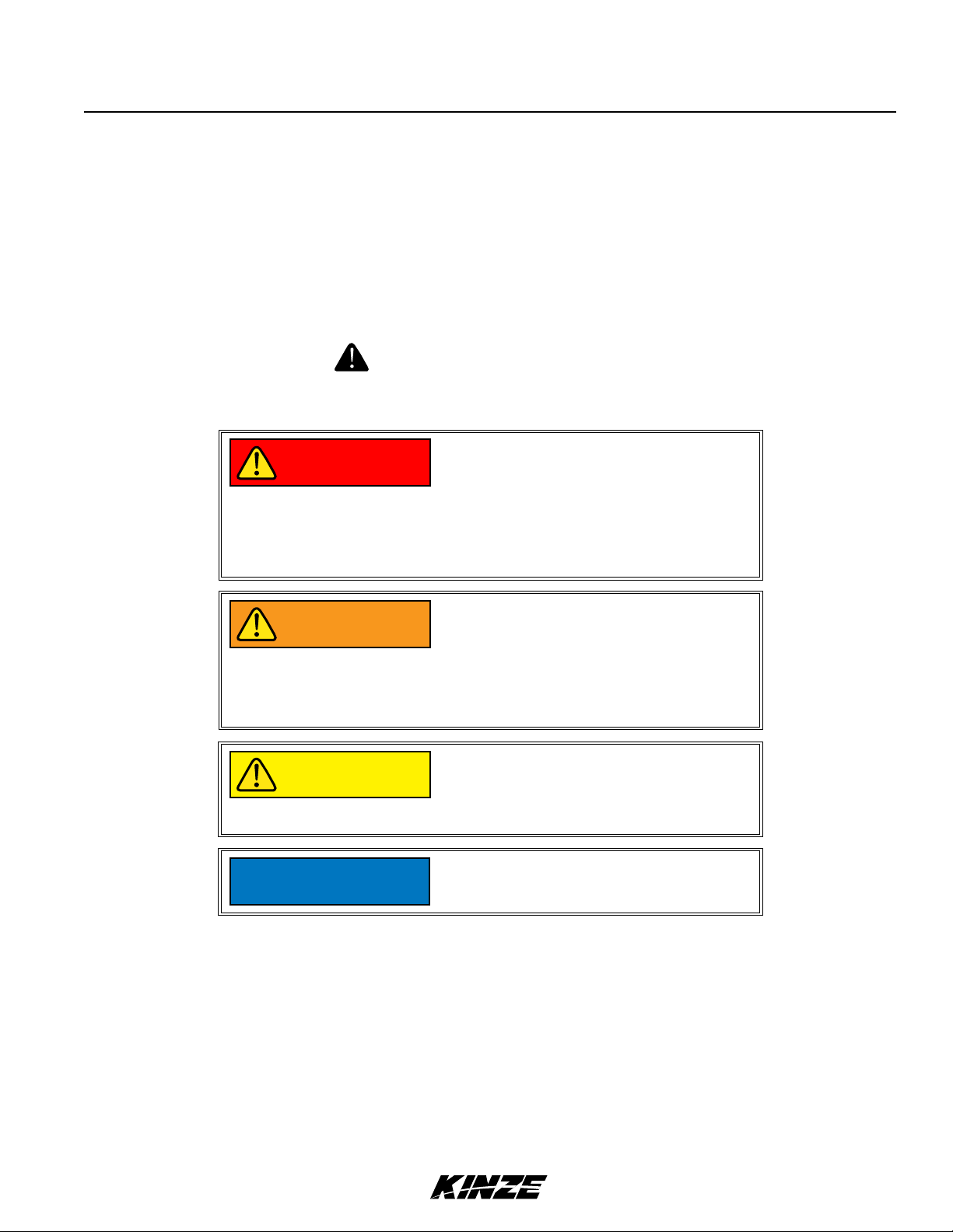
Throughout this manual the symbol and the words DANGER, WARNING, and CAUTION are used to call attention
to safety information that if not followed, will or could result in death or injury. NOTICE and NOTE are used to call your
attention to important information. The definition of each of these terms follows:
Indicates an imminently hazardous
DANGER
situation that, if not avoided, will
result in death or serious injury. This
signal word is to be limited to the most
extreme situations, typically for machine
components which, for functional
purposes, cannot be guarded.
Indicates a potentially hazardous
WARNING
CAUTION
NOTICE
NOTE: Special point of information or machine adjustment instructions.
situation that, if not avoided, could result
in death or serious injury, and includes
hazards that are exposed when guards
are removed. It may also be used to alert
against unsafe practices.
Indicates a potentially hazardous
situation that, if not avoided, may result
in minor or moderate injury. It may also
be used to alert against unsafe practices.
Used to address safety practices not
related to personal injury.
Rev. 1/18 1-3
TM
Page 8

Warranty
M0256-01Model 3140
The Kinze Limited Warranty for your new machine is stated on the retail purchaser’s copy of the Warranty And Delivery
Receipt form. Additional copies of the Limited Warranty can be obtained through your Kinze Dealer.
Warranty, within the warranty period, is provided as part of Kinze’s support program for registered Kinze products which
have been operated and maintained as described in this manual. Evidence of equipment abuse or modification beyond
original factory specifications will void the warranty. Normal maintenance, service and repair is not covered by Kinze
warranty.
To register your Kinze product for warranty, a Warranty And Delivery Receipt form must be completed by the Kinze
Dealer and signed by the retail purchaser, with copies to the Dealer, and to the retail purchaser. Registration must be
completed and submitted to Kinze Manufacturing, Inc. within 5 business days of delivery of the Kinze product to the retail
purchaser. Kinze Manufacturing, Inc. reserves the right to refuse warranty on serial numbered products which have not
been properly registered.
If service or replacement of failed parts which are covered by the Limited Warranty are required, it is the user’s responsibility
to deliver the machine along with the retail purchaser’s copy of the Warranty And Delivery Receipt to the Kinze Dealer
for service. Kinze warranty does not include cost of travel time, mileage, hauling or labor. Any prior arrangement made
between the Dealer and the retail purchaser in which the Dealer agrees to absorb all or part of this expense should be
considered a courtesy to the retail purchaser.
Kinze warranty does not include cost of travel time, mileage, hauling or labor.
Model 3140 12 Row 38" Vacuum Planter (Less Optional Row Markers) Shown In Transport Positon
Model 3140 12 Row 30" Mechanical Planter (With Optional Row Markers) Shown In Planting Positon
1-4 Rev. 1/18
TM
Page 9

Specifications
Model 3140M0256-01
GENERAL INFORMATION
The Model 3110 Mounted Planter is available with vacuum or mechanical meters, conventional hoppers, and various
other options. Contact your Kinze dealer for additional options which may be available for your specific model year planter.
Information in this manual was current at time of printing. However, due to Kinze’s ongoing product improvement, production
changes may cause your machine to appear slightly different in detail. Kinze Manufacturing, Inc. reserves the right to
change specifications or design without notice and without incurring obligation to install the same on machines previously
manufactured. To obtain the most recent version of your publication, please contact your Kinze dealer.
Right hand (R.H.) and left hand (L.H.), as used throughout this manual, are determined by facing in the direction the
machine will travel when in use, unless otherwise stated.
SPECIFICATIONS
Planter Size 12 Row 30" 12 Row 36"/38" 12 Row 38"/40" 16 Row 30"
Width - Transport
(Without Markers)
Width - Transport
(Includes Markers)
Width - Planting 30'-0" (9.1M) 37'-4" (11.4M) 40'-0" (12.2M) 40'-0" (12.2M)
Height - Transport
(Without Markers)
Height - Transport
(With Markers)
Weight (Mechanical) 6236 lb. (2828.6 kg) 6541 lb. (2966.9 kg) 6621 lb. (3003.2 kg) 7480 lb. (3392.9 kg)
Weight (Vacuum) 6794 lb. (3081.7 kg) 7127 lb. (3232.7 kg) 7214 lb. (3272.2 kg) 8109 lb. (3678.2 kg)
Toolbar (Mechanical) 7" x 7" x ¼" wall 7" x 7" x ¼" wall 7" x 7" x " wall 7" x 7" x " wall
Toolbar (Vacuum) 7" x 7" x " wall 7" x 7" x " wall 7" x 7" x " wall 7" x 7" x " wall
Seed Capacity 1.75 bu. (62 liters) (Vacuum/Hopper); 1.90 bu. (67 liters) (Mechanical/Hopper)
16'-1" (4.9M) 18'-5" (5.6M) 21'-1" (6.4M) 21'-1" (6.4M)
17'-9" (5.4M) 19'-6" (5.9M) 22'-2" (6.8M) 23'-0" (7.0M)
12'-6" (3.8M) 12'-6" (3.8M) 12'-6" (3.8M) 12'-6" (3.8M)
15'-6" (4.7M) 15'-6" (4.7M) 15'-6" (4.7M) 15'-6" (4.7M)
Tires
Drive System
Seed Transmission
Drive/Drill Shafts
Rev. 1/18 1-5
Four 7.60" x 15" 8 ply - adjustable height
Two 4.10" x 6" spring-loaded contact drive tires with no. 40 chain
Two wheel module-mounted, quick-adjust with machined sprockets and no. 40 chain
" hex drive/drill shafts
TM
Page 10

Specifications
TRACTOR HYDRAULIC REQUIREMENTS - MECHANICAL
Configuration Requirements Description
Base machine with mechanical
meters
Base machine with mechanical
meters and optional row marker
package
Base machine with mechanical
meters, optional row markers and
dual lift assist package
Base machine with mechanical
meters, optional row markers,
dual lift assist package, and wing
down flex package
*Some options may be combined to reduce the number of SCV outlets required.
1 SCV
2 SCV
3 SCV*
4 SCV*
10 gpm
(38 L/min)
20 gpm
(76 L/min)
20 gpm
(76 L/min)
20 gpm
(76 L/min)
#1 SCV: Planter fold
#1 SCV: Planter fold
#2 SCV: Row markers with sequencing/flow control valve
#1 SCV: Planter fold
#2 SCV: Row markers with sequencing/flow control valve
#3 SCV: Dual lift assist
#1 SCV: Planter fold
#2 SCV: Row markers with sequencing/flow control valve
#3 SCV: Dual lift assist
#4 SCV: wing down flex
M0256-01Model 3140
TRACTOR HYDRAULIC REQUIREMENTS - VACUUM
Configuration Requirements Description
Base machine with vacuum
meters (external case drain
required for vacuum hydraulic
circuit)
Base machine with vacuum
meters and optional row marker
package (external case drain
required for vacuum hydralulic
circuit)
Base machine with vacuum
meters, optional row marker
package, and dual lift assist
package option (external case
drain required for vacuum
hydralulic circuit)
Base machine with vacuum
meters, optional row marker
package, dual lift assist package
option and wing down flex
package
*Some options may be combined to reduce the number of SCV outlets required.
2 SCV
3 SCV
3 SCV*
5 SCV*
25 gpm
(95 L/min)
35 gpm
(132 L/min)
35 gpm
(132 L/min)
35 gpm
(132 L/
min)
#1 SCV: Vacuum meters
#2 SCV: Planter fold
#1 SCV: Vacuum metering
#2 SCV:
#3 SCV: Row markers with sequencing/flow control valve
#1 SCV: Vacuum meters
#2 SCV: Planter fold
#3 SCV: Row markers with sequencing/flow control valve
#4 SCV: Dual lift assist package
#5 SCV: Wing down flex package
#1 SCV: Vacuum meters
#2 SCV: Planter fold
#3 SCV: Row markers with sequencing/flow control valve
#4 SCV: Dual lift assist package
Planter fold
1-6 Rev. 1/18
TM
Page 11

General Safety Rules
Model 3140M0256-01
1. Read and understand instructions provided in this manual
and warning labels. Review these instructions frequently!
2. This machine is designed and built with your safety
in mind. Do not make any alterations or changes to this
machine. Any alteration to design or construction may
create safety hazards.
3. A large portion of farm accidents happen from fatigue
or carelessness. Safe and careful operation of tractor and
planter will help prevent accidents.
4.
Never allow planter to be operated by anyone unfamiliar
with operation of all functions of the unit. Operators must
read and thoroughly understand all instructions given in this
manual before operating or working on equipment.
5. Be aware of bystanders, particularly children! Always look
around to make sure it is safe to start tow vehicle engine or
move planter. This is particularly important with higher noise
levels and quiet cabs, as you may not hear people shouting.
6. Make sure planter weight does not exceed towing capacity
of tractor, or bridge and road limits. This is critical to maintain
safe control and prevent death or injury, or property and
equipment damage.
7. Never ride or allow others to ride on planter.
8. Store planter in an area away from human activity. DO
NOT permit children to play on or around the stored unit.
17. Make sure all safety/warning lights, SMV sign, and
reflective decals are in place and working properly before
transporting the machine on public roads.
18. Limit towing speed to 15 MPH. Tow only with farm tractor
of a minimum 90 HP. Allow for unit length when making turns.
19. Reduce speed prior to turns to avoid the risk of
overturning. Always drive at a safe speed relative to local
conditions and ensure your speed is slow enough for a safe
emergency stop.
20. Chemical application is often an integral part of planting.
Follow label instructions for proper chemical mixing, handling
and container disposal methods.
21. Be familiar with safety procedures for immediate first aid
should you accidentally contact chemical substances.
22. Use the proper protective clothing and safety equipment
when handling chemicals.
23. Chemicals are supplied with Material Safety Data Sheets
(MSDS) that provide full information about the chemical, its
effects on exposure, and first aid needs in the event of an
emergency. Keep your MSDS file up-to-date and available for
first responders in case of emergency.
24. When servicing ground engaging components such as
opening disks and firming points, use special care to avoid
points and edges worn sharp during use.
9. Keep hands, feet, and clothing away from moving parts.
Do not wear loose-fitting clothing which may catch in moving
parts.
10. Always wear protective clothing, shoes, gloves, hearing,
and eye protection applicable for the situation.
11. Do not allow anyone to stand between tongue or hitch
and towing vehicle when backing up to planter.
13. Prevent electrocution, other injuries, or property and
equipment damage. Watch for obstructions such as wires,
tree limbs, etc. when operating machine. Be aware of
clearances during turns and when folding/unfolding planter.
14. Reinstall all guards removed for maintenance activities.
Never leave guards off during operation.
15. Use of aftermarket hydraulic, electric, or PTO drives
may create serious safety hazards to you and people
nearby. If you install such drives, follow all appropriate safety
standards and practices to protect you and others near this
planter from injury.
16. Follow all federal, state/provincial, and local regulations
when towing farm equipment on a public highway. Use
safety chain (not an elastic or nylon/plastic tow strap) to
retain connection between towing and towed machines in
the event of primary attaching system separation.
25. Use professional help if you are unfamiliar with working
on hydraulic systems. Pressurized hydraulic fluid can
penetrate body tissue and result in death, serious infection,
or other injuries.
26. Disposing of waste improperly can threaten the
enviroment. To dispose of your equipment properly contact
your local environmental or recyling center.
Never pour waste onto the ground, down a drain, or into any
water source.
When disposing of waste such as oil, use leakproof
containers. Be sure to use containers that do not resemble
food or beverage which may mislead someone into
consuming them. Dispose of oil per your local, regional
requirements.
When disposing of any fertilizer chemicals used, contact the
supplier of the chemicals.
Model 3140 planter consists of 85% recyclable metals, 10%
recyclable plastic and rubber, and 5% waste.
Rev. 1/18 1-7
TM
Page 12
Safety Instructions, Signs, and Decals
M0256-01Model 3140
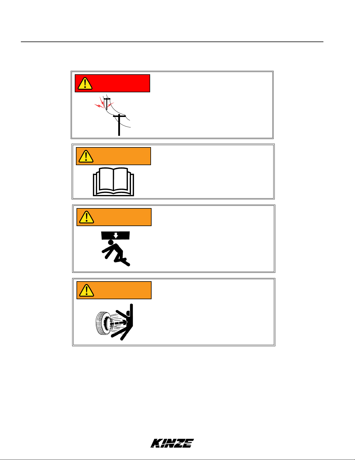
Following are some common hazard warnings associated with this equipment. Pay close attention to all safety,
operating, and maintenance information in this manual and decals applied to your equipment.
Contacting or coming close to power
DANGER
WARNING
lines or other high energy sources will
cause death or serious injury.
Keep away from power lines or high
energy sources at all times.
Improperly operating or working on
this equipment could result in death
or serious injury. Read and follow all
instructions in Operator Manual before
operating or working on this equipment.
WARNING
WARNING
Falling equipment can cause death or
serious injury. Install all lockup devices
or lower planter to ground before
working on equipment.
Explosive separation of rim and tire
parts can cause death or serious injury.
Overinflation, rim and tire servicing,
improper use of rims and tires, or worn
or improperly maintained tires could
result in a tire explosion.
1-8 Rev. 1/18
TM
Page 13

Model 3140M0256-01
SAFETY SIGNS AND DECALS
All safety/warning lights, reflective
WARNING
Safety signs and decals are placed on the machine to warn of hazards and provide important operating and maintenance
instructions. Information on these signs are for your personal safety and the safety of those around you. FOLLOW ALL
SAFETY INSTRUCTIONS!
• Keep signs clean so they can be easily seen. Wash with soap and water or cleaning solution as required.
• Replace safety signs if damaged, painted over, or missing.
decals, and SMV sign must be in place
and visible before transporting machine
on public roads or death, serious injury,
and damage to property and equipment
may result. Check federal, state/
provincial, and local regulations before
transporting equipment on public roads.
• Check reflective decals and SMV sign periodically. Replace if they show any loss of of reflective properties.
• When replacing decals, clean machine surface thoroughly with soap and water or cleaning solution to
remove all dirt and grease.
NOTE: Safety sign and decal locations are shown in the Parts Manual for this machine.
NOTE: Style and locations of SMV sign, reflective decals, and safety/warning lights conform to
ANSI/ASABE S279.14 JUL 2008 and ANSI/ASABE S276.6 JAN 2005.
Rev. 1/18 1-9
TM
Page 14

This page left blank intentionally.
Page 15
Machine Operation
Model 3140M0256-01
The following information is general in nature and was written to aid the operator in preparation of the tractor and
planter for use, and to provide general operating procedures. The operator's experience, familiarity with the machine
and the following information should combine for efficient planter operation and good working habits.
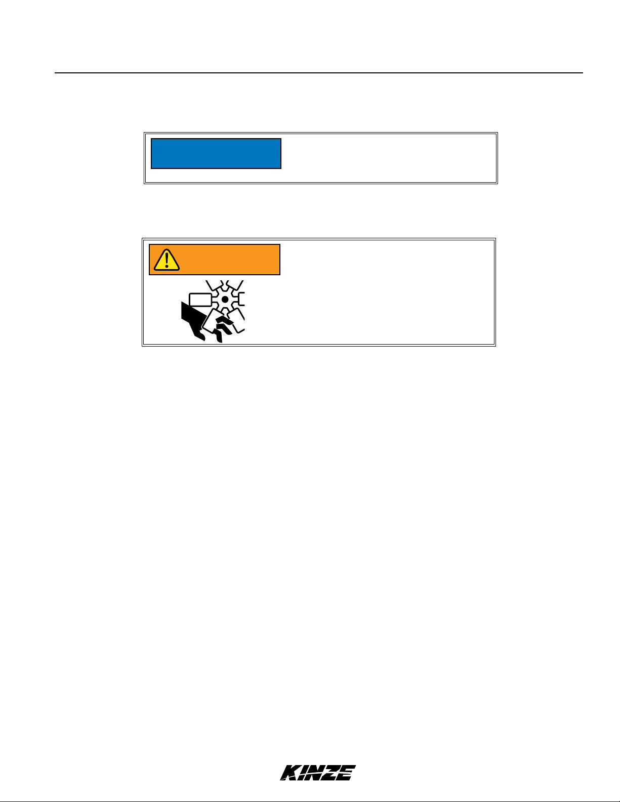
Always raise planter out of ground when
NOTICE
The Kinze Vacuum Seed Metering System includes seed meters, seed discs and an air system consisting of a
hydraulic driven vacuum fan which draws air through manifolds and hoses and the seed meters on each row unit.
WARNING
making sharp turns or backing up or
tractor and equipment may be damaged.
Moving fan blades can cause amputation
or severe injury. Never operate vacuum
fan with cover removed.
The dual lift assist wheel option requires a customer-supplied quick hitch to operate without the center link pin. 8 row
wide planters require removal of the center section gauge wheels to accommodate dual lift assist wheels.
INITIAL PREPARATION OF THE PLANTER
Lubricate the planter and row units per the lubrication information in this manual. Make sure all tires have been
properly inflated. See “Tire Servicing”. Check all drive chains for proper tension, alignment and lubrication.
Rev. 1/18 2-1
TM
Page 16

Machine Operation
M0256-01Model 3140
TRACTOR REQUIREMENTS
All Hydraulic Requirements: Minimum
NOTICE
Approximate minimum tractor horsepower (HP) required for field work is listed below:
12 Row Narrow - 150 HP And Up
12 Row Wide And 16 Row Narrow - 180 HP And Up
NOTE: Tractor must have adequate 3 point hitch lift capacity to lift weight of machine, attachments, seed and
dry chemicals. Shipping weights do not include seed, dry chemicals or additional optional attachments.
Tractor front end stability is necessary for safe and efficient operation. Therefore, it may be necessary to add front
ballast to your tractor for satisfactory field operation, as well as adequate transport stability. Refer to your tractor
operator’s manual for front ballast recommendations.
Pressure 2350 PSI (16202.6 kPa); Maximum
Pressure 3000 PSI (20684.2 kPa). Check
tractor hydraulics to ensure that maximum
pressure cannot be exceeded.
Vacuum
A 12 volt DC electrical system is required on all sizes to operate planter safety/warning lights.
One SCV remote hydraulic outlet is required to operate the row markers, one to operate planter fold and one plus a
zero pressure case drain is required to operate the seed metering system vacuum fan.
Maximum hydraulic flow rate of 13 GPM (49 L/min) @ 2000 PSI (13789.5 kPa) is required to operate the seed
metering system vacuum fan.
NOTE: A Flow Control Needle Valve Kit, to provide a flow
control option for tractors that are not equipped with a
method for finite adjustment of hydraulic flow, is available
from Kinze Repair Parts through your Kinze Dealer.
G1K426 Needle Valve Kit
TRACTOR PREPARATION AND HOOKUP
1. Set tractor rear wheel spacing at double the planter row spacing. For example: On a planter set for 38" rows, set the
tractor wheel spacing at 76" (193 cm) center-to-center. On wide front end tractors set front wheel spacing equal to
rear wheel spacing. Check tractor operator’s manual for correct front and rear tire pressure.
2. Adjust lift links on tractor so the planter will lift level from side to side and raise high enough for planter transport
clearance. Set the sway blocks on the tractor in position to prevent side sway. Be sure the individual lift link arms are
in the float position.
2-2 Rev. 1/18
TM
Page 17
Machine Operation
Model 3140M0256-01
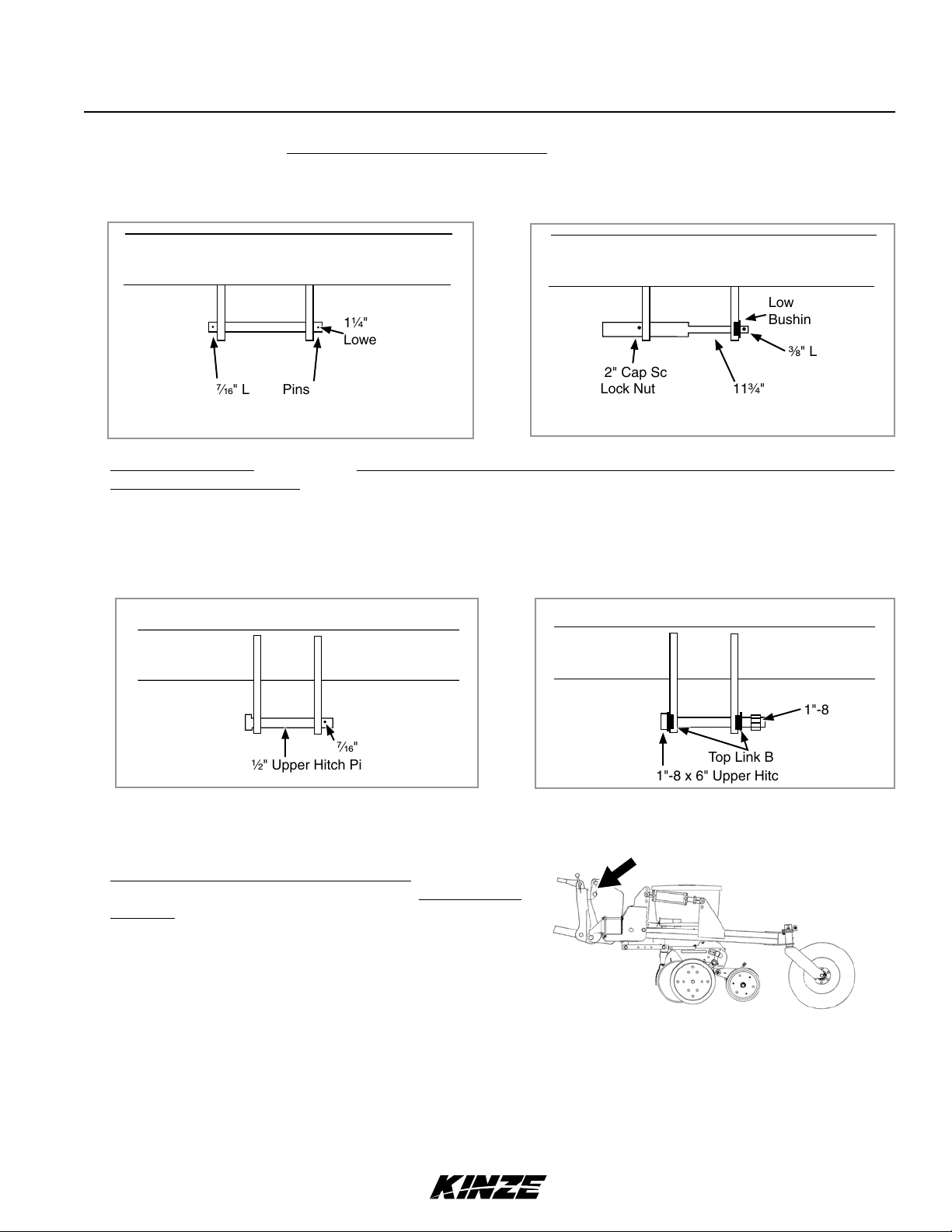
3. Back tractor up to planter. Position lower hitch pins and bushings as shown in the following diagrams for your type of
tractor hitch. Line up holes and insert hitch pins and lock in place with pins provided. It may be necessary to change
the length of the upper link with the adjusting handle.
Lower Hitch Pins
TOP VIEW TOP VIEW
Lower Link
1¼" x 8¾"
Lower Hitch Pin
" x 2" Cap Screw
/" Lynch Pins
and Lock Nut
Optional Category 2 Pin And HardwareCategory 3N And 3 Pin And Hardware
The upper hitch point has two holes. The hitch pin must be positioned in the lower hole for use with tractors equipped
with Category 2 quick hitch. The lower hole is also recommended for use on tractors without a quick hitch. Some
Category 2 tractors without a quick hitch are designed to accommodate the upper attaching holes. Consult tractor
manufacturer.
Bushing (D10418)
" Lynch Pin
11¾" Lower Hitch Pin
The hitch pin must be positioned in the upper hole for use with tractors equipped with Category 3N and 3 hitches.
Upper Hitch Pin
Category 3N And 3 Pin And Hardware
TOP VIEW
USE TOP
SET OF
HOLES
1¼" x 4½" Upper Hitch Pin
⁄" Lynch Pin
Optional Category 2 Pin And Hardware
TOP VIEW
USE
1"-8 Lock Nut
BOTTOM
SET OF
HOLES
1"-8 x 6" Upper Hitch Pin (Cap Screw)
Top Link Bushings (D10419)
When using a quick hitch (customer-supplied), match pin location to pin spacing in the quick hitch. Adjust the tractor
upper link until the quick hitch is vertical when in the planting position.
Dual lift assist wheel equipped machines require use of
a quick hitch (customer-supplied) and the top link pin is
not used.
Rev. 1/18 2-3
TM
Page 18
Machine Operation
M0256-01Model 3140
Never transport machine with lift assist
WARNING
4. The planter is equipped with safety/warning lights which should be used whenever the planter is being transported.
The connector is a 7 terminal breakaway connector conforming to ASAE standards. If your tractor is not equipped
for safety/warning lights, check with your tractor dealer.
Vacuum
Connect harness on planter to digital vacuum gauge console on tractor. Connect power lead from digital vacuum
gauge console to power source. A power lead adapter may be required.
WARNING
wheels without quick hitch. If this type
of hitch is not in place, a sudden stop
could allow the toolbar to rotate forward
causing personal injury or damage to the
equipment.
Pressurized hydraulic fluid can penetrate
body tissue and result in death, serious
infection, or other injuries. Fluid injected
under skin must be IMMEDIATELY
removed by a surgeon familiar with this
type of injury. Make sure connections
are tight and hoses and fittings are
not damaged before applying system
pressure. Leaks can be invisible. Keep
away from suspected leaks. Relieve
pressure before searching for leaks or
performing any system maintenance.
Wipe hose ends to remove any dirt
NOTICE
5. Connect hydraulic hoses to tractor ports in a sequence that is both familiar and comfortable to the operator. See
“Hydraulic Operation”.
Before attaching hoses, move tractor SCV levers back and forth to relieve any pressure in the tractor hydraulic system.
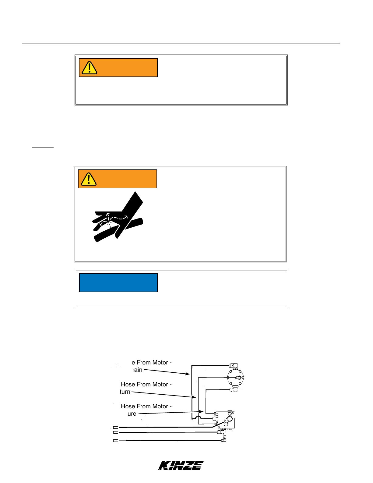
The vacuum seed metering system vacuum fan operation hydraulic hoses are as follows:
" Hose From Motor -
Case Drain
¾" Hose From Motor -
Return
½" Hose From Motor -
Pressure
before connecting couplers to tractor
ports or contamination may cause
equipment failure.
2-4 Rev. 1/18
TM
Page 19

NOTICE
DANGER
Machine Operation
Model 3140M0256-01
Before the markers are operated, make
sure all marker lockups are in working
position.
Before applying pressure to the hydraulic
system, make sure all connections are
tight and that hoses and fittings have not
been damaged. Hydraulic fluid escaping
under pressure can have sufficient
force to penetrate skin causing injury or
infection.
Rev. 1/18 2-5
TM
Page 20
Machine Operation
M0256-01Model 3140
6. With planter on a level surface, raise the planter slowly and watch for any interference.
When raising a planter equipped with dual lift assist wheels, the front of the planter should raise and then the
back using the lift assist wheels to raise the rear of the planter. When lowering the planter, the lift assist wheels
should begin to lower the rear of the planter before lowering the front of the planter. If the dual lift assist wheels
are plumbed into the 3 point hitch lift circuit, adjust the flow control valve so the rear of the planter lowers before
the front of the planter and the front of the planter raises before the rear of the planter. See “Flow Control Valve
Adjustment”. With planter lowered to planting position, adjust tractor linkage to level the toolbar. See “Leveling The
Planter”.
With planter (equipped with dual lift assist wheels) raised for transport, maintain a minimum of 3" (7.6 cm)
clearance between planter and quick hitch.
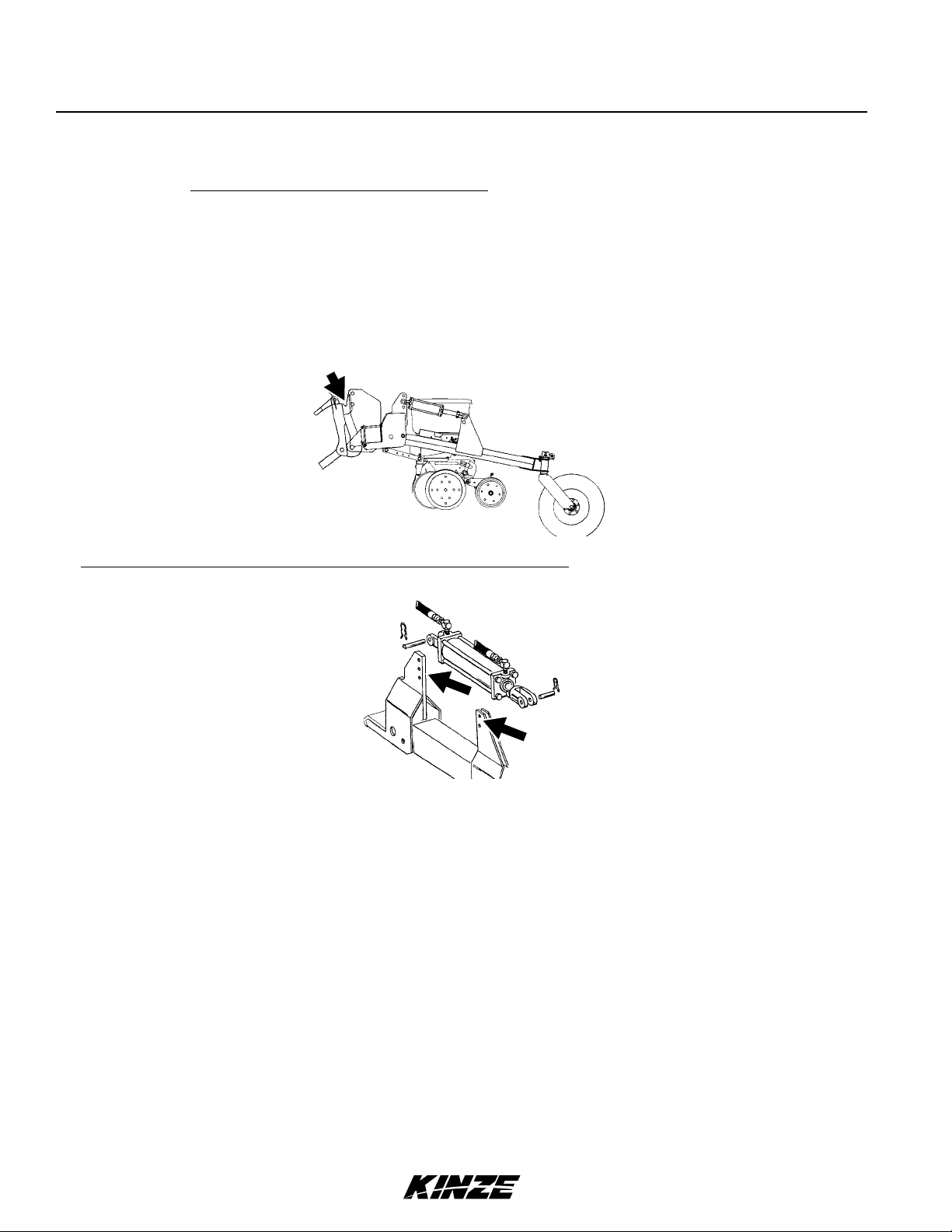
On planters equipped with the optional Dual Lift Assist Wheel Package, adjustment holes on the lift assist cylinder
mounts allow for adjustment of lift height.
7. Remove pin from each parking stand and raise each to the transport position. Secure stands in raised position with
pin in lowest hole.
8. Lower the planter so the drive wheels rest on the ground and check to be sure planter is level. Readjust top link as
required to level row units. See “Leveling The Planter”.
2-6 Rev. 1/18
TM
Page 21

Intended Use
Piston
Gland
Tube
Rod
End Mounts
Tube Seal
Rod Seal
Rod Wiper
Piston Seal
Product
Category
Maximum
Stroke
Working
Pressure
Bore Size
Shaft
Diameter
Cylinder
Configuration
Cylinder
Action
Material
Mounting
Method
Mount
Location
Cylinder
Style
Machine Operation
Model 3140M0256-01
CYLINDER INFORMATION
Wing Fold Cylinder,
Wing Fold Cylinder,
12 Row 30" (A9036)
Double acting
applications.
Ductile iron Ductile iron Ductile iron Ductile iron Ductile iron
Ductile iron Ductile iron Ductile iron Ductile iron Ductile iron
ST 52 Dom ST 52 Dom ST 52 Dom ST 52 Dom ST 52 Dom
1045 Nitro rod 1045 Nitro rod 1045 Nitro rod 1045 Nitro rod 1045 Nitro rod
Sleeve Sleeve Sleeve Sleeve Sleeve
Buna O-ring with
polytemp back-up
Polyester alloy u-cup Polyester alloy u-cup Polyester alloy u-cup Polyester alloy u-cup Polyester alloy u-cup
Polyester alloy
snap in
T-seal hnbr T-seal hnbr T-seal hnbr T-seal hnbr T-seal hnbr
12 Row 36"/38"/40"
and 16 Row 30"
(A9060)
Double acting
applications.
Buna O-ring with
polytemp back-up
Polyester alloy
snap in
Specifications
Hydraulic cylinder Hydraulic cylinder Hydraulic cylinder Hydraulic cylinder Hydraulic cylinder
20" (50.8 cm) 20" (50.8 cm) 20.062" (50.95 cm) 3.5" (8.9 cm) 3.5" (8.9 cm)
3000 psi
(20684.27 kPa)
3.5" (8.89 cm) 4" (10.16 cm) 2.5" (6.35 cm) 4" (10.16 cm) 8" (20.32 cm)
1.5" (3.8 cm) 1.75" (4.44 cm) 1.25" (3.17 cm) 1.75" (4.44 cm) ---
Simple Simple Simple Simple Simple
Double Double Double Double Double
Steel, Ductile iron Steel, Ductile iron Steel, Ductile iron Steel, Ductile iron Steel, Ductile iron
Sleeve Sleeve Sleeve Sleeve Sleeve
End Cap End Cap End Cap End Cap End Cap
Welded Welded Welded Welded Welded
3000 psi
(20684.27 kPa)
Row Marker
(Cushion) Cylinder
(A8895)
Double acting
applications.
Buna O-ring with
polytemp back-up
Polyester alloy
snap in
3000 psi
(20684.27 kPa)
Wing Down Flex
Cylinder (A9055)
Double acting
applications.
Buna O-ring with
polytemp back-up
Polyester alloy
snap in
3000 psi
(20684.27 kPa)
Dual Lift Assist
Cylinder
(A5482)
Double acting
applications.
Buna O-ring with
polytemp back-up
Polyester alloy
snap in
3000 psi
Rev. 1/18 2-7
TM
Page 22

Part Number
Description
Product
Category
Product Form
I.D.
O.D.
Minimum Bend
Radius
Working
Pressure
Temperature
Range
Material
Specialized
Construction
Media
Application
Machine Operation
M0256-01Model 3140
HYDRAULIC HOSE INFORMATION
A8261 A12015 A3352 A8262 A3353 A12014
Hose Assembly,
½" x 13½"
(10F-10F)
Hydraulic Hose Hydraulic Hose Hydraulic Hose Hydraulic Hose Hydraulic Hose Hydraulic Hose
Hose; Assembly Hose; Assembly Hose; Assembly Hose; Assembly Hose; Assembly Hose; Assembly
.500" (12.7 mm) .375" (9.52 mm)
.800" (20.32 mm)
2.8" (7.11 cm) 2" (5.08 cm) 3.8" (9.65 cm) 2.8" (7.11 cm) 3.8" (9.65 cm) 2" (5.08 cm)
3250 PSI
(22407.96 kPa)
-40°F - +212°F
(-40°C - +100°C)
Modified Nitrile
Type C2
High tensile
steel wire
Hydraulic Fluid Hydraulic Fluid Hydraulic Fluid Hydraulic Fluid Hydraulic Fluid Hydraulic Fluid
Agricultural;
Construction
Hose Assembly,
" x 17" (6F-6F)
.630" (16 mm) 1.110" (28.19 mm)
3250 PSI
(22407.96 kPa)
-40°F - +212°F
(-40°C - +100°C)
Modified Nitrile
Type C2
High tensile
steel wire
Agricultural;
Construction
Hose Assembly,
/" x 13½"
(12F-12F)
.750" (19.05 mm)
3500 PSI
(24131.65 kPa)
-40°F - +212°F
(-40°C - +100°C)
Modified Nitrile
Type C2
High tensile
steel wire
Agricultural;
Construction
Hose Assembly,
½" x 36"
(10F-10F)
.500" (12.7 mm)
.800" (20.32 mm)
3250 PSI
(22407.96 kPa)
-40°F - +212°F
(-40°C - +100°C)
Modified Nitrile
Type C2
High tensile
steel wire
Agricultural;
Construction
Hose Assembly,
/" x 33"
(12F-12F)
.750" (19.05 mm)
1.110" (28.19 mm) .630" (16 mm)
3500 PSI
(24131.65 kPa)
-40°F - +212°F
(-40°C - +100°C)
Modified Nitrile
Type C2
High tensile
steel wire
Agricultural;
Construction
Hose Assy
3/8x34
(06F-06F)
.375" (9.52 mm)
3250 PSI
(22407.96 kPa)
-40°F - +212°F
(-40°C - +100°C)
Modified Nitrile
Type C2
High tensile
steel wire
Agricultural;
Construction
Part Number
Description
Product
Category
Product Form
I.D.
O.D.
Minimum Bend
Radius
Working
Pressure
Temperature
Range
Material
Specialized
Construction
Media
Application
A8247 A3337 A3266 A1188 A1103 A1113
Hose Assembly,
½" x 60"
(8M-10F)
Hydraulic Hose Hydraulic Hose Hydraulic Hose Hydraulic Hose Hydraulic Hose Hydraulic Hose
Hose; Assembly Hose; Assembly Hose; Assembly Hose; Assembly Hose; Assembly Hose; Assembly
.500" (12.7 mm)
.800" (20.32 mm)
2.8" (7.11 cm) 3.8" (9.65 cm) 2" (5.08 cm) 2" (5.08 cm) 4" (10.16 cm) 4" (10.16 cm)
3250 PSI
(22407.96 kPa)
-40°F - +212°F
(-40°C - +100°C)
Modified Nitrile
Type C2
High tensile
steel wire
Hydraulic Fluid Hydraulic Fluid Hydraulic Fluid Hydraulic Fluid Hydraulic Fluid Hydraulic Fluid
Agricultural;
Construction
Hose Assembly,
/" x 60"
(8M-12F)
.750" (19.05 mm)
1.110" (28.19 mm) .630" (16 mm)
3500 PSI
(24131.65 kPa)
-40°F - +212°F
(-40°C - +100°C)
Modified Nitrile
Type C2
High tensile
steel wire
Agricultural;
Construction
Hose Assembly,
/" x 60"
(8M-6F)
.375" (9.52 mm) .250" (6.35 mm) .250" (6.35 mm) .250" (6.35 mm)
3250 PSI
(22407.96 kPa)
-40°F - +212°F
(-40°C - +100°C)
Modified Nitrile
Type C2
High tensile
steel wire
Agricultural;
Construction
Hose Assembly,
¼" x 66"
(06F-06F)
.530" (13.46 mm) .530" (13.46 mm) .530" (13.46 mm)
3250 PSI
(22407.96 kPa)
-40°F - +212°F
(-40°C - +100°C)
Modified Nitrile
Type C2
High tensile
steel wire
Agricultural;
Construction
Hose Assembly,
¼" x 110"
(6F-6F)
3275 PSI
(22580.33 kPa)
-40°F - +212°F
(-40°C - +100°C)
Modified Nitrile
Type C2
High tensile
steel wire
Agricultural;
Construction
Hose Assembly,
¼" x 80"
(6F-6F)
3275 PSI
(22580.33 kPa)
-40°F - +212°F
(-40°C - +100°C)
Modified Nitrile
Type C2
High tensile
steel wire
Agricultural;
Construction
2-8 Rev. 1/18
TM
Page 23

Part Number
Description
Product
Category
Product Form
I.D.
O.D.
Minimum Bend
Radius
Working
Pressure
Temperature
Range
Material
Specialized
Construction
Media
Application
Machine Operation
Model 3140M0256-01
HYDRAULIC HOSE INFORMATION
A1170 A1198 A1102 A1116 A1140 A7600
Hose Assembly,
¼" x 90"
(6F-6F)
Hydraulic Hose Hydraulic Hose Hydraulic Hose Hydraulic Hose Hydraulic Hose Hydraulic Hose
Hose; Assembly Hose; Assembly Hose; Assembly Hose; Assembly Hose; Assembly Hose; Assembly
.250" (6.35 mm) .250" (6.35 mm) .250" (6.35 mm) .250" (6.35 mm) .250" (6.35 mm) .250" (6.35 mm)
.530" (13.46 mm) .530" (13.46 mm) .530" (13.46 mm) .530" (13.46 mm) .530" (13.46 mm) .530" (13.46 mm)
4" (10.16 cm) 4" (10.16 cm) 4" (10.16 cm) 4" (10.16 cm) 4" (10.16 cm) 4" (10.16 cm)
3275 PSI
(22580.33 kPa)
-40°F - +212°F
(-40°C - +100°C)
Modified Nitrile
Type C2
High tensile
steel wire
Hydraulic Fluid Hydraulic Fluid Hydraulic Fluid Hydraulic Fluid Hydraulic Fluid Hydraulic Fluid
Agricultural;
Construction
Hose Assembly,
¼" x 60"
(8M-6F)
3275 PSI
(22580.33 kPa)
-40°F - +212°F
(-40°C - +100°C)
Modified Nitrile
Type C2
High tensile
steel wire
Agricultural;
Construction
Hose Assembly,
¼" x 95"
(6F-6F)
3275 PSI
(22580.33 kPa)
-40°F - +212°F
(-40°C - +100°C)
Modified Nitrile
Type C2
High tensile
steel wire
Agricultural;
Construction
Hose Assembly,
¼" x 136"
(6F-6F)
3275 PSI
(22580.33 kPa)
-40°F - +212°F
(-40°C - +100°C)
Modified Nitrile
Type C2
High tensile
steel wire
Agricultural;
Construction
Hose Assembly,
¼" x 52"
(6F-6F)
3275 PSI
(22580.33 kPa)
-40°F - +212°F
(-40°C - +100°C)
Modified Nitrile
Type C2
High tensile
steel wire
Agricultural;
Construction
Hose Assembly,
¼" x 260"
(6F-6F)
3275 PSI
(22580.33 kPa)
-40°F - +212°F
(-40°C - +100°C)
Modified Nitrile
Type C2
High tensile
steel wire
Agricultural;
Construction
Part Number
Description
Product
Category
Product Form
I.D.
O.D.
Minimum Bend
Radius
Working
Pressure
Temperature
Range
Material
Specialized
Construction
Media
Application
A7601 --- --- --- --- ---
Hose Assembly,
¼" x 80"
(6M-6F)
Hydraulic Hose --- --- --- --- ---
Hose; Assembly --- --- --- --- ---
.250" (6.35 mm) --- --- --- --- ---
.530" (13.46 mm)
4" (10.16 cm) --- --- --- --- ---
3275 PSI
(22580.33 kPa)
-40°F - +212°F
(-40°C - +100°C)
Modified Nitrile
Type C2
High tensile
steel wire
Hydraulic Fluid --- --- --- --- ---
Agricultural;
Construction
--- --- --- --- ---
--- --- --- --- ---
--- --- --- --- ---
--- --- --- --- ---
--- --- --- --- ---
--- --- --- --- ---
--- --- --- --- ---
Rev. 1/18 2-9
TM
Page 24
Machine Operation
M0256-01Model 3140
LEVELING THE PLANTER
For proper performance of the planter and row units, it is important that the planter frame and row unit parallel arms
operate approximately level. The toolbar should operate at a 20" to 22" (51-56 cm) height, measured from the
planting surface to the bottom of the toolbar.
When operating the planter, make sure the right and left lower link arms on the tractor are adjusted equally before
attaching the planter. After the planter has been lowered to the correct operating height, stop the tractor and stand
beside the planter and check to be sure the frame is level fore and aft. If the row units angle up or down, adjust the
center link on the tractor to level the machine.
It is important for the planter to operate level laterally. Tire pressure must be maintained at pressures specified and
drive wheel height must be adjusted equally. See “Wheel Module Height Adjustment”.
TRANSPORTING PLANTER
Contacting or coming close to power
DANGER
lines or other high energy sources will
cause death or serious injury.
Keep away from power lines or high
energy sources at all times.
All safety/warning lights, reflective
WARNING
• Tow only with farm tractor rated and configured for equipment.
• Know your route and be aware of any obstructions.
• Follow all road and bridge load limit restrictions.
• Never exceed maximum transport towing speed of 20 mph (32 kph).
decals, and SMV sign must be in place
and visible before transporting machine
on public roads or death, serious injury,
and damage to property and equipment
may result. Check federal, state/
provincial, and local regulations before
transporting equipment on public roads.
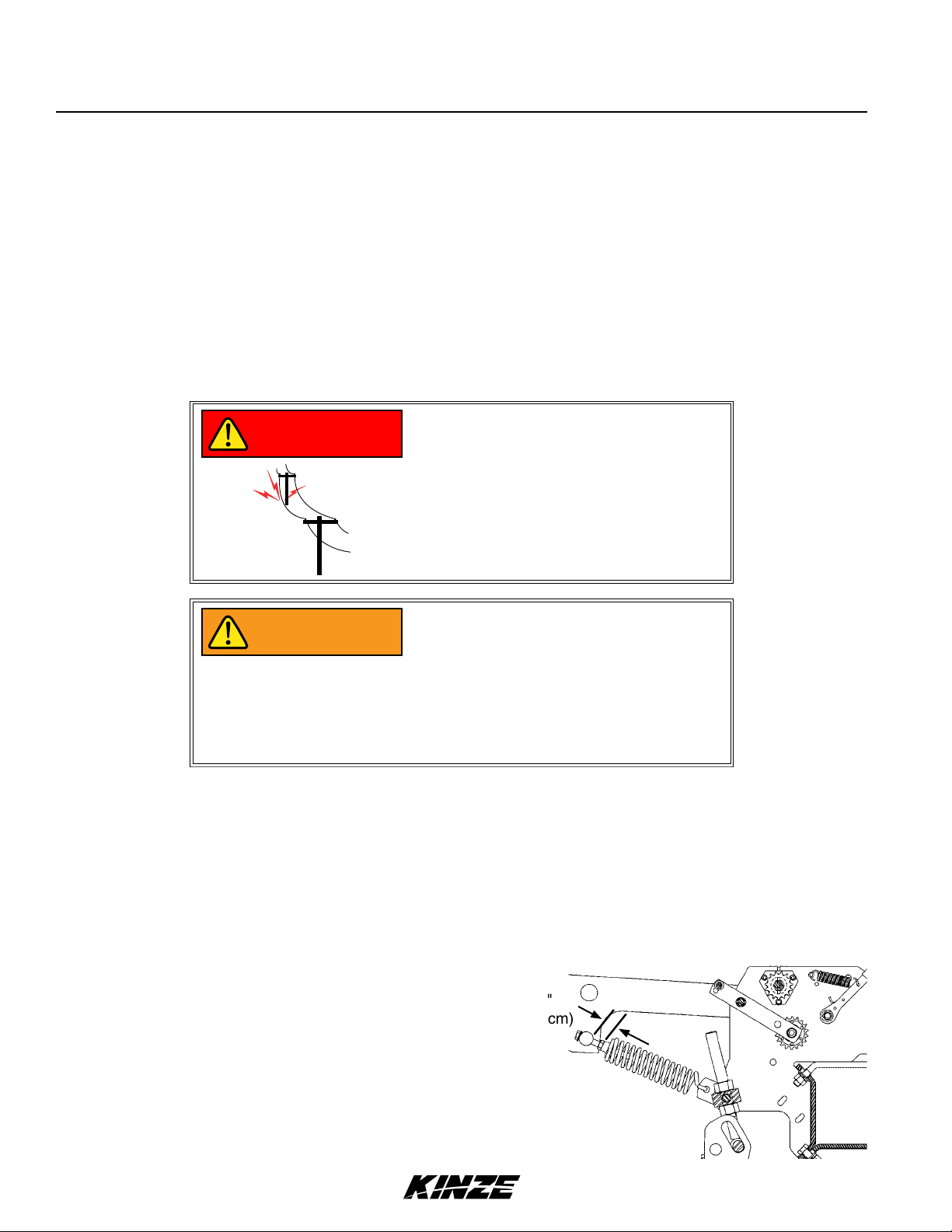
CONTACT WHEEL SPRING ADJUSTMENT
There are two down pressure springs on each contact drive
wheel. The spring tension is factory preset and should require
no further adjustment.
The tension is set leaving 1" (2.5 cm) between the spring plug
and the mounting shaft as shown below.
1"
(2.5 cm)
2-10 Rev. 1/18
TM
Page 25
Machine Operation
Model 3140M0256-01
PARKING STAND ADJUSTMENT
Vacuum Shown
Two parking stands, located on the front side of the main frame, are standard on all Model 3140 planters. The stands
must be positioned so they are not directly behind the tractor tire or they will interfere when the planter is raised.
Each parking stand has six positioning holes. By using these positioning holes, you can set the main frame parking
height from 19" to 25" (48 to 63.5 cm).
Raise the stands to the top position and pin when planting; lower and pin for parking and storage.
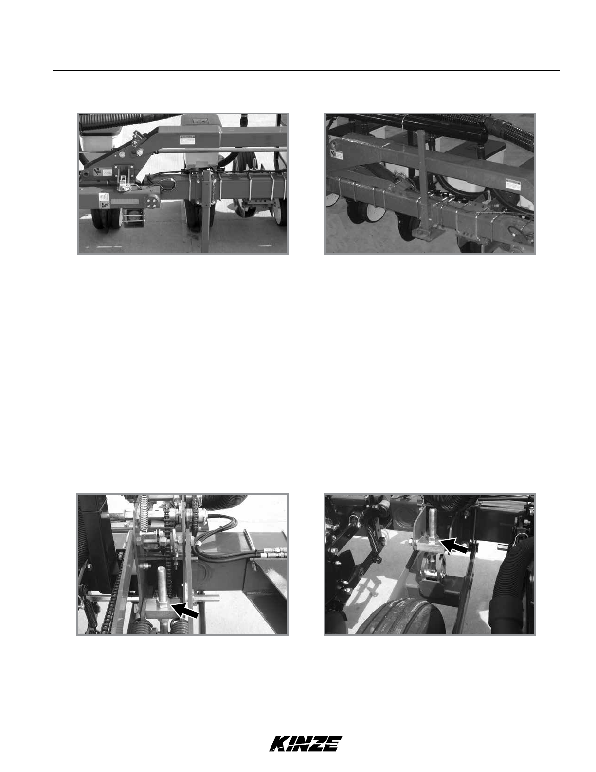
WHEEL MODULE HEIGHT ADJUSTMENT
Drive Wheel Module Assembly
Center Section Gauge Wheel Assembly
The drive wheel module assembly and center section gauge wheel assembly are designed so the drive wheel height
can be adjusted to maintain a frame height of 20" to 22" (51-56 cm) in all planting applications. This is particularly
useful when the planter is used for ridge planting or planting on beds. The wheel module assembly has an adjustment
range of 7" (18 cm). To adjust the wheel assembly, loosen the upper nut using a 1½" wrench or a 15" adjustable
wrench and turn the lower nut using a 1½" wrench or 15" adjustable wrench (clockwise to decrease frame height or
counterclockwise to increase frame height). Tighten the upper nut after adjustment is complete. Set all wheels equally.
Rev. 1/18 2-11
TM
Page 26
Machine Operation
M0256-01Model 3140
SEED RATE TRANSMISSION ADJUSTMENT
Planting population rate changes are made at the seed rate transmissions. The seed rate transmissions are designed
to allow simple, rapid changes of sprockets to obtain the desired planting population. By removing the lynch pins
on the hexagon shafts, sprockets can be interchanged with those from the sprocket storage rod bolted near each
transmission.
Chain tension is controlled by spring-loaded, dual-sprocket idlers. The idler assembly is adjusted with a easy-release
arm. This arm has a release position to remove spring tension for replacing sprockets. The amount of spring tension
on the chain is controlled by the idler arm. See “Wrap Spring Wrench Operation”.
A decal positioned near each transmission illustrates proper chain routing. The planting rate charts found in “Rate
Charts” will aid you in selecting the correct sprocket combinations.
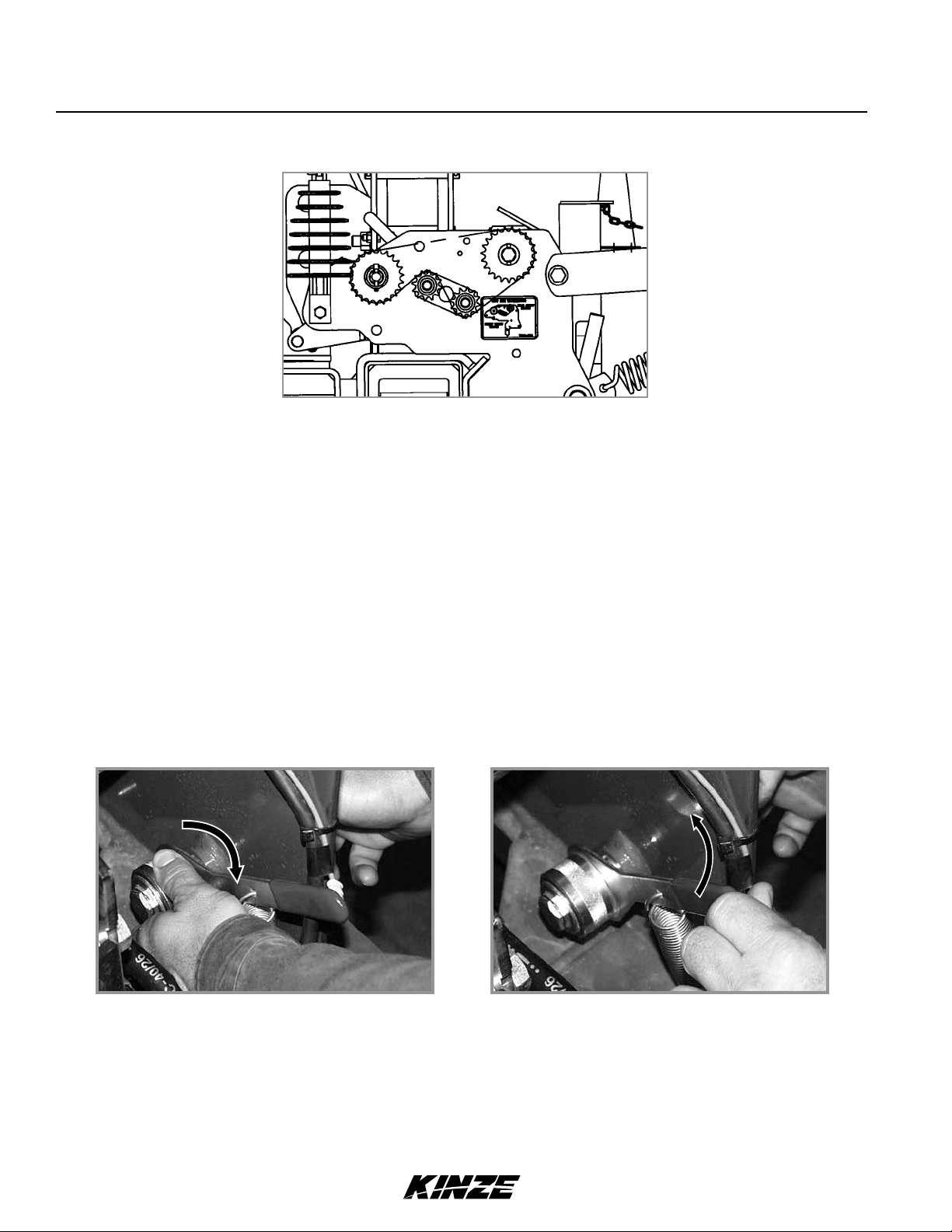
WRAP SPRING WRENCH OPERATION
Release Chain Tension Increase Chain Tension
Chain idlers are equipped with wrap spring wrenches. L.H. wrap spring wrenches have a blue release collar and R.H.
wrap spring wrenches have a grey or black release collar.
Rotate collar on wrap spring wrench and pull handle to release chain tension.
Rotate chain idler into chain and pull handle to tension idler spring.
2-12 Rev. 1/18
TM
Page 27
Machine Operation
Model 3140M0256-01
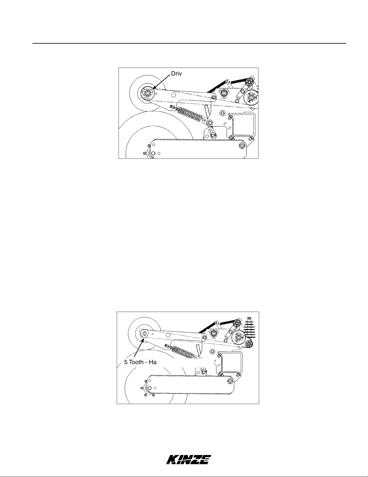
CONTACT WHEEL DRIVE SPROCKETS
Drive Sprocket
NOTE: 15 tooth, 19 tooth or 30 tooth drive sprockets at each contact drive wheel can be interchanged from the
sprocket storage rod bolted near each transmission. The 15 and 19 tooth sprockets require use of a 218 pitch
No. 40 chain. The 30 tooth sprocket requires use of a 224 pitch No. 40 chain.
Chain tension is controlled by a spring-loaded sprocket idler. The amount of spring tension on the chain is controlled
by the idler arm.
The planting rate charts found in “Rate Charts” section will aid you in selecting the correct sprocket.
NOTE: 15, 19 and 30 tooth drive sprockets are NOT applicable to all rate charts. Check chart titles to ensure the
proper rate charts are selected.
NOTE: After each sprocket combination adjustment, make a field test to be sure you are planting at the desired rate.
HALF RATE (2 TO 1) DRIVE
15 Tooth - Half Rate (2 To 1) Drive
Half rate (2 to 1) drive is recommended only when the desired population falls below that shown on the planting rate charts.
Replace the 30 tooth drive sprocket and shorter No. 40 110 pitch chain on each contact wheel with a 15 tooth sprocket.
This will reduce the planter transmission speed and reduce planting and application rates by approximately 50%.
NOTE: After each sprocket combination adjustment, make a field check to be sure you are planting at the
desired rate.
Rev. 1/18 2-13
TM
Page 28

Machine Operation
M0256-01Model 3140
SHEAR PROTECTION
/" Shear Pin
Transmission Shaft
The planter driveline and seed and granular chemical drivelines are protected from damage by shear pins.
If excessive load should cause a pin to shear, it is important to determine where binding has occurred before replacing
the pin. Replace shear pins with same size and type.
To prevent future binding or breakage of components, check driveline alignment and follow prescribed lubrication schedules.
NOTE: Drill shaft/transmission coupler alignment is critical.
DIGITAL VACUUM READOUT
Digital vacuum readout is incorporated into in-cab display. Refer to the display operation manual for instructions.
2-14 Rev. 1/18
TM
Page 29
Machine Operation
Model 3140M0256-01
VACUUM METER SYSTEM
Kinze vacuum meter seed metering system includes seed meters, seed discs, and an air system consisting of a
hydraulic driven vacuum fan which draws air through manifolds, hoses, and seed meters on each row unit.
Moving fan blades can cause amputation
WARNING
or severe injury. Never operate vacuum
fan with cover removed.
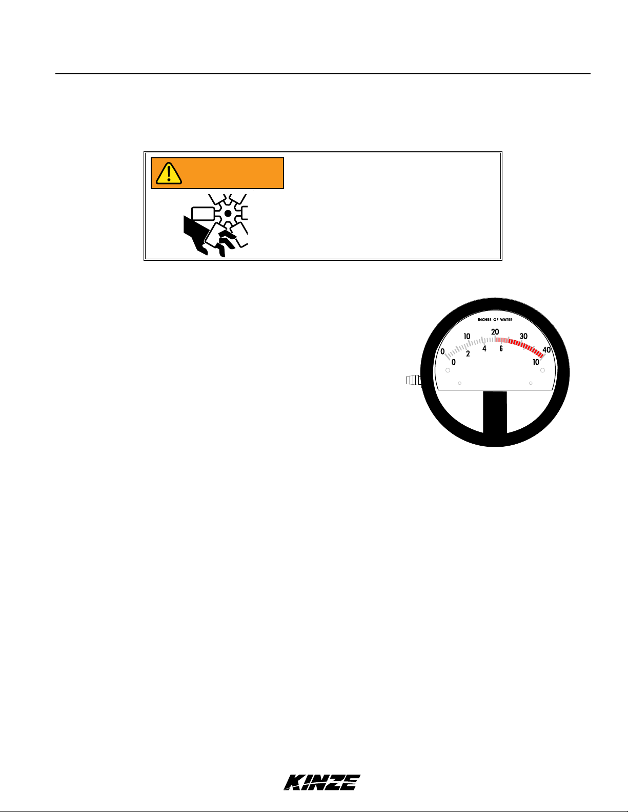
ANALOG VACUUM OR PRESSURE GAUGE
Analog vacuum or pressure gauge connects directly to vacuum
meter (vacuum) or bulk fill (pressure) manifold and is teed into
digital sending units.
Only adjustment is to “zero” needle with no vacuum or
KILOPASCALS
8
pressure present. If there is a significant difference between
gauge and a reading taken at meters, a different manifold
MAX PRESSURE 15 PSIG (103 KPA)
location should be found to connect hose to gauge and digital
sending unit.
Analog Gauge
NOTE: Analog gauges are identical EXCEPT for plug and hose barb locations in side of gauge housing.
DO NOT connect vacuum meter or bulk fill hose to wrong gauge. Check plug and hose barb installation if
readout is erratic or appears inaccurate.
VACUUM FAN MOTOR VALVE BLOCK ASSEMBLY
A pressure relief valve in the hydraulic circuit prevents build up of oil pressure over 35 PSI in case drain line when
vacuum fan motor is operating. This valve will vent oil outside valve block through a drain hole in the aluminum valve
block. This can occur whenever case drain is improperly connected or pressure in motor circuit builds.
See “Hydraulic Diagram - Vacuum Fan Motor System” in Lubrication and Maintenance section.
Valve block contains a check valve that prevents vacuum fan from operating in wrong direction if pressure is applied to
return side of motor and allows fan to coast to a stop when tractor hydraulic control is returned to neutral position.
NOTE: Fan turns at a reduced speed If reverse pressure is applied.
Rev. 1/18 2-15
TM
Page 30
HYDRAULIC OPERATION
Machine Operation
M0256-01Model 3140
Vacuum Seed
Metering
Wing Down
Flex OR
Dual Lift Assist
Wing Fold
Marker
Vacuum Seed
Metering
Marker
Wing Fold
Wing Down
Flex AND
Dual Lift Assist
Vacuum
Planter may require up to four selective control valves (SCV). A single SCV is needed to fold the wings; a second
SCV and case drain is required for operation of the vacuum seed metering system; a third SCV is required for the
Row Marker Package; and a fourth SCV is required for the Dual Lift Assist Wheel Package and/or the Wing Down Flex
Cylinder Package unless these are connected into the tractor 3 point lift system.
Mechanical
Planter requires a single control valve for folding the wings. A second control valve is required for the Row Marker
Package. A third valve is required for the Dual Lift Assist Wheel Package and/or the Wing Down Flex Cylinder Package
unless these are connected into the tractor 3 point lift system.
Contacting or coming close to power
DANGER
lines or other high energy sources will
cause death or serious injury.
Keep away from power lines or high
energy sources at all times.
NOTE: If a cylinder has been disconnected or removed for any reason, do not attach the rod end of the
cylinder until the cylinder is cycled several times to remove any air that may be trapped in the system.
The wings are folded and unfolded using a single hydraulic control valve. When the wings are unfolded, the springactuated hydraulic latches lock the wings to the fold links so they pivot as one unit.
Always be sure planter is in the fully
NOTICE
raised position before folding the planter
wings to ensure wing row units do not
collide with center section seed hoppers.
2-16 Rev. 1/18
TM
Page 31

Machine Operation
ROW MARKER HYDRAULIC OPERATION
WARNING
DANGER
Model 3140M0256-01
Row marker can lower at any time and
could cause death or serious injury. Stay
away from row markers! Install safety
lockup device when not in use.
Contacting or coming close to power
lines or other high energy sources will
cause death or serious injury.
Keep away from power lines or high
energy sources at all times.
The single valve marker system uses a sequencing valve which directs hydraulic flow to operate the markers
alternately. Each time a marker is raised, the sequencing valve will direct flow to lower the opposite marker.
Both markers can be used at the same time if desired. To do this, lower the planter and the marker that has been
selected. Move the tractor SCV control to the raise position and immediately return it to the lower position. This will
shift the marker control valve and the remaining marker will be lowered.
Rev. 1/18 2-17
TM
Page 32

Machine Operation
M0256-01Model 3140
ROW MARKER SPEED ADJUSTMENT
Flow control valves located in the marker sequencing/flow
control valve assembly control lowering and raising speed of
markers. One flow control valve sets lowering speed of both
markers and one sets raising speed of both markers. To adjust
marker speed, loosen jam nut and turn control(s) clockwise,
or IN to slow travel speed and counterclockwise, or OUT, to
increase travel speed. Flow control(s) determine amount of oil
flow restriction through valves, therefore varying travel speed of
markers. Tighten jam nut after adjustments are complete.
NOTE: Backing flow control valve out too far can cause the o-ring seal on valve to fail when hydraulics are operated.
"
Maximum
The flow controls should be properly
NOTICE
adjusted before the marker assemblies
are first put into use. Excessive marker
travel speed can damage the marker
assembly.
Flow Control
Marker Lower
Flow Control
Marker Raise
Row marker can lower at any time and
WARNING
NOTE: When oil is cold, hydraulics operate slowly. Make sure all adjustments are made with warm oil. Do not
overtighten lock nut.
NOTE: On a tractor where oil flow can not be controlled, the rate of flow of oil from tractor may be greater
than rate at which the marker cylinder can accept oil. Tractor hydraulic control lever will have to be held until
cylinder reaches end of its stroke. This occurs most often on tractors with open center hydraulic systems. On
tractors with closed center hydraulic systems, the tractor’s hydraulic flow control can be set so the tractor’s
detent will function properly.
could cause death or serious injury. Stay
away from row markers! Install safety
lockup device when not in use.
2-18 Rev. 1/18
TM
Page 33

Machine Operation
Model 3140M0256-01
ROW MARKER ADJUSTMENTS
1. Multiply number of rows by the average row spacing in inches to determine total planting width.
Row Marker Lengths
2. Lower planter and row marker assembly to ground.
3. Measure from planter center line to a point where blade contacts ground.
4. Adjust row marker extension so distance from marker disc blade to center line of planter is equal to total planting
width. Adjust right and left row marker assemblies equally and securely tighten clamping bolts.
12 Row 30" 360" (914.4 cm)
12 Row 36" 432" (1097.3 cm)
12 Row 38" 456" (1158.2 cm)
12 Row 40" 480" (1219.2 cm)
16 Row 30" 480" (1219.2 cm)
Loosen hardware to
Loosen hardware to
adjust marker length.
adjust blade angle.
Depth band
Concave side faces
towards planter.
Row marker disc blade angle adjustment
Setting marker disc blade assembly at a
NOTICE
sharper angle than needed adds stress
to row marker assembly and shortens
bearing and blade life. Set blade angle
only as needed to leave a clear mark.
Marker disc blade is installed with concave side facing inward. Spindle assembly is slotted so hub and blade can be
angled to throw more or less dirt.
5. Loosen hardware and move assembly as required.
6. Tighten bolts to specified torque.
7. Do a field test to ensure markers are properly adjusted.
NOTE: A notched marker blade is available from Kinze through your Kinze Dealer for use in more severe no
till conditions.
Rev. 1/18 2-19
TM
Page 34

Machine Operation
DANGER
DANGER
WARNING
M0256-01Model 3140
Contacting or coming close to power
lines or other high energy sources will
cause death or serious injury.
Keep away from power lines or high
energy sources at all times.
Wings must be unfolder before detaching
machine from tractor.
Always install hydraulic cylinder safety
lockups when servicing the machine in
raised position or when transporting the
machine on the road.
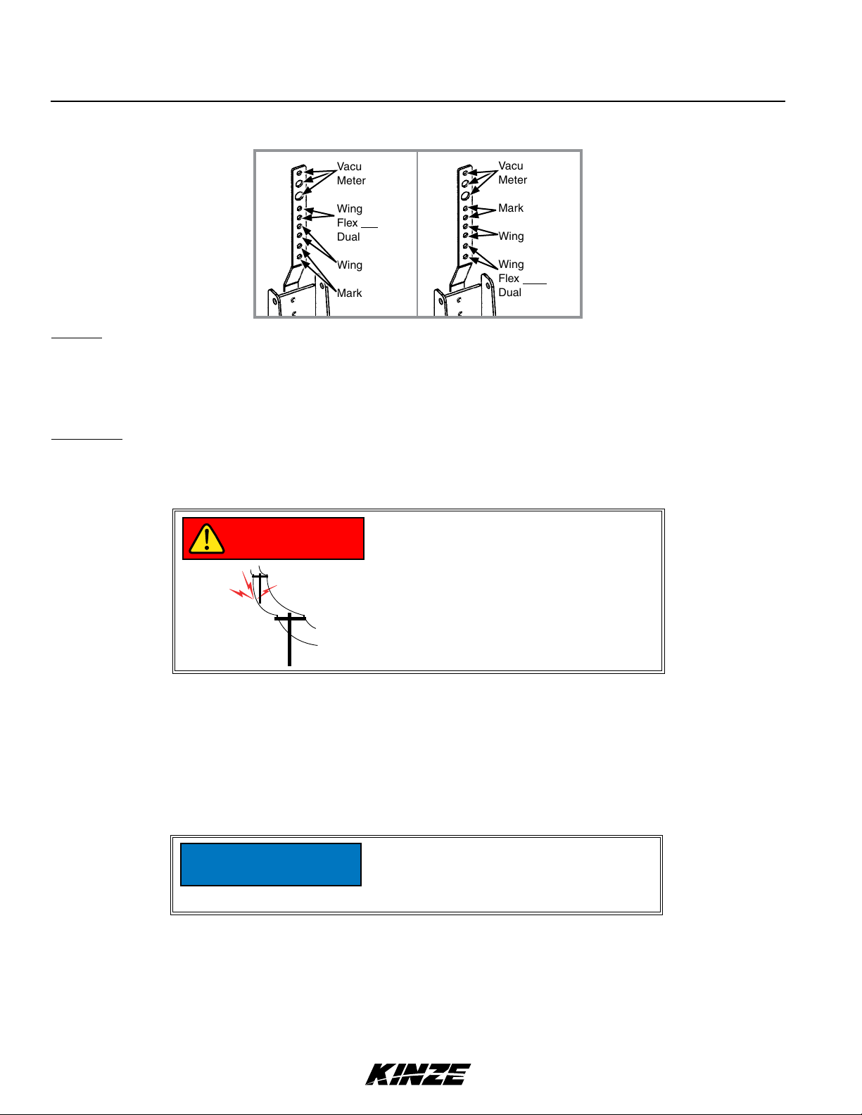
WING FLEX
Two hooks located over each wing hinge area can be positioned so toolbar (a) is locked rigid, (b) so planter wings
have 8° up flex or (c) with Wing Down Flex Cylinder Package (See “Wing Down Flex Cylinder”) installed, so planter
wings have 8° up flex and 8° down flex.
½" x 6" Cap Screw And Sleeve
" x 6¾" Pin
Long Notch Up
Hooks Positioned For Rigid Operation
To change the hook from one position to the other:
1. Lower the planter to the ground so weight is off of the toolbar and relieve hydraulic pressure in the wing fold cylinders.
2. Remove lynch pin and 6¾" pin.
Long Notch Down
Hooks Positioned For 8° Up Flex
1¼" x 11¼" Hinge Pin
¾" x 2½" Cap Screws
" x 6¾" Pin
3. Loosen ¾" hook mounting hardware and rotate the hooks back off of the hinge pin. (It may be necessary to raise the
outer end of the wing up several inches to take pressure off of the hooks to allow them to rotate.)
4. Remove ½" x 6" cap screw and sleeve.
(Continued on next page)
2-20 Rev. 1/18
TM
Page 35

Machine Operation
Model 3140M0256-01
WING FLEX (CONTINUED)
5. Remove ¾" hook mounting hardware.
6. Install hooks in new position. Tighten ¾" hardware.
7. Install sleeve and ½" cap screw in opposite hole.
NOTE: The ⁄" hook mounting hardware should be snug, yet loose enough to allow the hooks to be rotated by hand.
8. Install 6¾" pin and lynch pins.
WING DOWN FLEX CYLINDER
½" x 6" Cap Screw And Sleeve
" x 6¾" Pin And Lynch Pins
1¼" x 11¼" Hinge Pin
¾" x 2½" Cap Screws
Hooks Positioned Over Hinge Pin For Transport
Wing Down Flex Cylinder Installed
To Allow 8° Up Flex And 8° Down Flex
Hooks
To prevent the planter wings from sagging during transport should hydraulic pressure be lost, the hooks located over
each hinge area should be repositioned prior to folding the planter. Apply hydraulic pressure to the wing down flex
cylinders until they are completely retracted and the wings are rotated up slightly. (⁄" hook mounting hardware
should be snug, yet loose enough to allow the hooks to be rotated by hand.) Remove lynch pin and 6¾" pin,
rotate hooks to hook over hinge pin as shown below and reinstall 6¾" pin above hooks. Relieve hydraulic pressure
on down flex cylinders and allow wings to come back to level. Fold planter and install lockups on wing fold cylinders.
Reverse procedure to unfold planter.
Always be sure planter is in the fully
NOTICE
raised position before folding the planter
wings to ensure wing row units do not
collide with center section seed hoppers.
Rev. 1/18 2-21
TM
Page 36

Machine Operation
POINT ROW CLUTCHES
With the use of electric-activated clutches, which disengage
the drive, either half of the planter may be shut off for finishing
up fields or for long point row situations.
The selector switch for the clutches is located in the point row
clutch control box which is installed on the tractor.
NOTE: Switch should be left in OFF position when planter
is not in use. If left in ON (left or right) position, the tractor
battery will be discharged.
M0256-01Model 3140
L.H. Side Of Planter Shown
Point Row Clutch Control Box
NOTE: Since the liquid fertilizer piston pump have their own drive wheels, liquid fertilizer application will not be
affected by use of the point row clutch.
Stop Output Wrap Input
Collar Hub Spring Hub
Control Tang
The point row clutch consists of a wrap spring riding on an input hub and an output hub. During operation the wrap
spring is wrapped tightly over the hubs connecting them in a positive engagement. The greater the force of rotation
the tighter the grip of the spring on the hubs. Rotation in the opposite direction or stopping the spring from rotating
prevents the transmission of torque from the input hub to the output hub stopping the planter drive.
The input end of the spring is bent outward and is referred to as the control tang. The control tang fits into a slot in the
stop collar that is located between the input and output hubs and over the wrap spring. If the stop collar is allowed to
rotate with the input hub, the clutch is engaged. If the stop collar is stopped from rotating the control tang connected to
it is forced back and the spring opens. This allows the input hub to continue rotating without transmitting torque to the
output hub; therefore, stopping the planter drive.
The stop collar is controlled by the use of an electric solenoid and an actuator arm. When the selector switch on the
tractor control box is in the OFF position the solenoid coil is NOT ENERGIZED and the actuator arm will not contact
the stop on the stop collar allowing it to rotate with the hubs and drive the planter.
When the operational switch is in the “DISENGAGE” (right or left) position the solenoid coil IS ENERGIZED and the
plunger in the solenoid coil pulls the actuator arm against the stop on the stop collar, disengaging the wrap spring and
stopping the planter drive.
2-22 Rev. 1/18
TM
Page 37

Machine Operation
1 2 3
1 2 3
(-)
(-)
(+)
1 2 3
TWO-SPEED POINT ROW CLUTCHES
Two-Speed Clutch Assembly
Model 3140M0256-01
Left Side Of Planter Viewed From Rear Of Planter
Top View Of Control Box
The optional Two-Speed Point Row Clutch Package is designed to allow on-the-go population rate adjustment as well
as the capability to shut off either half of the planter for finishing up fields or for long point row situations.
The point row clutches are controlled by the point row clutch
switches on the control box. The point row switch is used to
shut off either the left or right half of the planter. Activating
the reduced rate switch engages one solenoid on each clutch
assembly and reduces the planting rate for the entire planter.
NOTE: Point row switch should be left in OFF position and
rate switch left in FULL RATE position when planter is not
in use. If left in ON and/or REDUCED RATE positions, the
tractor battery will be discharged.
L.H. Side Shown
The ratio of population reduction is determined by the sprocket
30 Tooth Driven Sprocket
ratio between the drive and driven sprockets at the contact
drive tire. A rate reduction decal like the one shown below is
located on the wheel module.
Rev. 1/18 2-23
TM
Drive
Sprocket
Page 38

Machine Operation
M0256-01Model 3140
DUAL LIFT ASSIST WHEELS
Dual lift assist wheel equipped machines require use of a quick hitch (customer-supplied) and the top link pin is not used.
A single control valve operates the dual lift assist wheels.
When raising a planter equipped with dual lift assist wheels, the front of the planter should raise and then the back
using the lift assist wheels to raise the rear of the planter. When lowering the planter, the lift assist wheels should
begin to lower the rear of the planter before lowering the front of the planter.
If the machine is equipped with both the Dual Lift Assist Wheel Package and Wing Down Flex Cylinder Package, a
single control valve operates both options. As the dual lift assist wheel cylinders extend to raise the toolbar, the wing
down flex cylinders retract to flex the wings up 5° for added clearance when turning.
The flow control valve must be adjusted so that the wing down flex cylinders start to retract before the lift assist
cylinders start to raise the toolbar. This will prevent the wings from drooping as the toolbar is raised.
Dual lift assist wheels hydraulics can also be plumbed into the 3 point lift circuit. A flow control valve determines the
correct sequence of events to allow the dual lift assist wheel cylinders to operate at the correct time in conjunction with
the 3 point hitch lift circuit. See “Flow Control Valve Adjustment”.
See “Tractor Preparation And Hookup” for additional information.
ACCUMULATOR
An accumulator is standard in Dual Lift Assist Wheel Packages for Model 3140 Stack Folding 16 Row 30" Planters to
absorb shock loads to the lift assist wheel arms during transport.
After initial dealer installation no maintenance should be necessary on the sealed system.
Do not disassemble accumulator. See
WARNING
dealer for service. Note manufacturer’s
caution decal on accumulator.
2-24 Rev. 1/18
TM
Page 39

Machine Operation
PISTON PUMP MOUNT/DRIVE SPRING ADJUSTMENT
Adjust the pump drive tension springs by tightening the hex
head adjustment bolts to maintain positive tire contact. The
initial setting should result in a " gap between coils. Tighten
jam nut against spring plug to hold setting.
FLOW CONTROL VALVE ADJUSTMENT
Model 3140M0256-01
Spring Tension
Adjusting Bolt
Jam Nut
Initial Setting
Approx. " Gap
Between Coils
The flow control valve determines the amount of oil flow to the lift assist cylinders.
To adjust oil flow, loosen the jam nut and turn the control clockwise or “in” to restrict flow and counterclockwise or “out”
to increase the flow.
PLANTING SPEED
Planters are designed to operate within a speed range of 2 to 8 mph (3.2 - 12.8 kph). See “Rate Charts”. Variations in
ground speed produce variations in rates. Finger pickup seed meter populations tend to be disproportionately higher at
high ground speeds.
NOTE: Seed spacing can be adversely affected at speeds above 5.5 mph (8.8 kph).
Rev. 1/18 2-25
TM
Page 40

Machine Operation
M0256-01Model 3140
FIELD TEST
Perform a field test with any change of field and/or planting conditions, seed size or planter adjustment to ensure
proper seed placement and operation of row units.
Check planter for front to rear and lateral level operation. See “Leveling the Planter”.
Check all row units to be certain they are running level. Row unit parallel arms should be approximately parallel to
the ground when planting.
Check row markers for proper operation and adjustment. See “Row Marker Adjustments” and “Row Marker Speed
Adjustment”.
Check for proper application rates and placement of granular chemicals on all rows. See “Field Check Granular
Chemical Application”.
Check for desired depth placement and seed population on all rows. See “Check Seed Population” and
appropriate Rate Chart.
Check for proper application rates of fertilizer on all rows. See proper “Fertilizer Application Rate Chart”.
Reinspect machine after field testing.
Hoses And Fittings
Bolts And Nuts
Cotter Pins And Spring Pins
Drive Chain Alignment
CHECK SEED POPULATION
1. Tie up one or more sets of closing wheels by running a
chain or rubber tarp strap between the hopper support
panel and closing wheels. It may be necessary to decrease
closing wheel arm spring tension.
Chain, rubber tarp
strap, or similar.
Planting depth
adjustment handle
2. Plant a short distance and check to see if seed is visible
in the seed trench. Adjust planting depth to a shallower
setting if seed is not visible and recheck.
Deeper Shallower
Planting depth adjustment
2-26 Rev. 1/18
TM
Page 41

Machine Operation
Model 3140M0256-01
3. Measure of an acre. See chart for correct distance for row width being planted. For example, if planting 30"
rows of an acre would be 17' 5".
Acre Seed Population Count Row Width/Distance
Row Width 15" 18" 19" 30" 36" 38"
Distance 34'10" 29'0" 27'8" 17'5" 14'6" 13'10"
NOTE: Seeds may bounce or roll when planting with closing wheels raised and planting depth set shallow
affecting seed spacing accuracy.
4. Count seeds in measured distance.
5. Multiply number of seeds placed in of an acre by 1000. This gives total population.
EXAMPLE: 30" row spacing 17' 5" equals acre.
26 seeds counted x 1000 = 26,000 seeds per acre
Seed count can be affected by drive wheel and seed meter drive ratio, tire pressure, and/or seed meter malfunction.
1. If seed check shows average distance between seeds in inches is significantly different than seed rate chart
indicates, first check drive ratio between drive wheel and seed meter. Check drive wheel air pressure, check for
incorrect sprocket(s) in driveline and check drive and driven sprockets on transmission(s) for proper selection.
2. Check for seed meter malfunction. For example, if spacing between kernels of corn at the transmission setting
being used is 8" and a gap of 16" is observed, a finger has lost its seed and not functioned properly. If two seeds
are found within a short distance of each other, the finger has metered two seeds instead of one.
3. See “Finger Pickup Seed Meter Troubleshooting” and/or “Brush-Type Seed Meter Troubleshooting” in the
Troubleshooting Section of this manual.
Rev. 1/18 2-27
TM
Page 42

Machine Operation
M0256-01Model 3140
DETERMINING POUNDS PER ACRE (BRUSH-TYPE METER)
Seeds per acre ÷ Seeds per pound (from label) = Pounds per acre
If seeds per pound information is not available use the following averages:
2,600 seeds per pound for medium size soybeans
15,000 seeds per pound for medium size milo/grain sorghum
4,500 seeds per pound for medium size cotton
DETERMINING BUSHELS PER ACRE
Pounds per acre ÷ Seed unit weight = Bushels per acre
Average Unit Weight of:
1 Bushel Soybeans = 60 Pounds
1 Bushel Milo/Grain Sorghum = 56 Pounds
1 Bushel Cotton = 32 Pounds
If seed population check shows planting rate is significantly different than seed rate chart shows or if a particular
meter is not planting accurately, see “Brush-Type Seed Meter Maintenance” and “Brush-Type Seed Meter
Troubleshooting”.
2-28 Rev. 1/18
TM
Page 43

Machine Operation
Model 3140M0256-01
FIELD CHECK GRANULAR CHEMICAL APPLICATION
Temperature, humidity, speed, ground conditions, flowability of different material, or meter obstructions can affect
granular chemical rate of delivery.
Agricultural chemicals can cause death
WARNING
Perform a field check to determine application rates.
or serious injury to persons, animals,
and plants or seriously damage soil,
equipment, or property. Read and
follow all chemical and equipment
manufacturers labels and instructions.
Calibrated vial
Granular chemical field check
1. Fill insecticide and/or herbicide hoppers.
2. Attach a calibrated vial to each granular chemical meter.
NOTE: Disengage clutch to avoid dropping seed during test.
3. Lower planter and drive 1320 feet at planting speed.
4. Weigh chemical in ounces caught in one vial.
5. Multiply that amount by factor shown to determine pounds per acre.
Pounds Per Acre
Row Width Factor
30" .83
36" .69
38" .65
EXAMPLE: You are planting 30" rows. You have planted for 1320 feet at desired planting speed. You caught 12.0
ounces of chemical in one vial. 12.0 ounces times 0.83 equals 9.96 pounds per acre.
NOTE: Check calibration of all rows.
METERING GATE
Use metering gate setting as a starting point for distributing insecticide or herbicide. Charts are based on 5 mph
(8 kph) planting speed. Use a higher gate setting for speeds faster than 5 mph (8 kph) and a lower setting for speeds
slower than 5 mph (8 kph).
Rev. 1/18 2-29
TM
Page 44

This page left blank intentionally.
Page 45
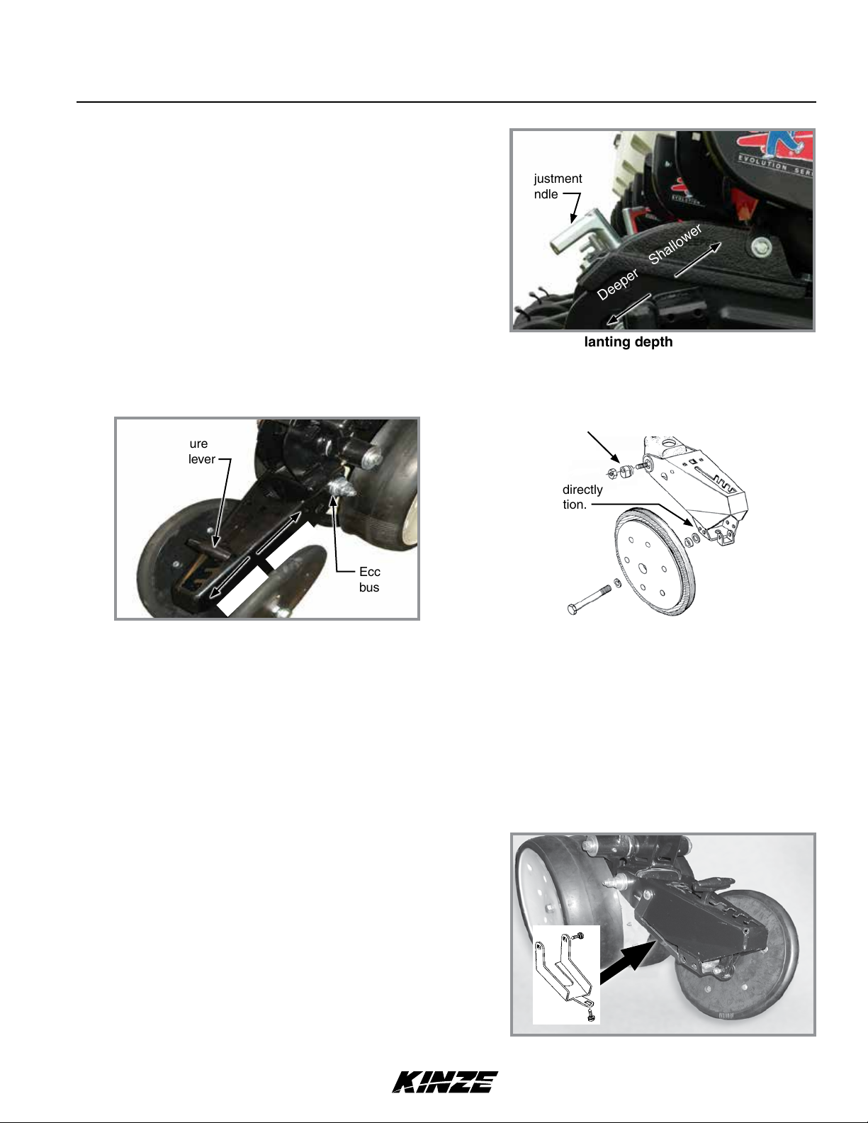
Row Unit Operation
Model 3140M0256-01
PLANTING DEPTH
Planting
Planting depth is maintained by adjustable row unit gauge
wheels. Depth adjustment range is approximately ½" to 3½"
(1.27 to 8.89 cm).
depth
adjustment
handle
1. Raise planter to remove weight from wheels.
2. Push down on depth adjustment handle and reposition
it forward to decrease or rearward to increase planting
depth. Initially adjust all units to the same setting.
3. Lower planter and check operation and planting depth
of all row units. Readjust individual rows as needed for
Planting depth adjustment
uniform operation.
“V” CLOSING WHEEL ADJUSTMENT (RUBBER OR CAST IRON)
Eccentric bushing
Down pressure
adjustment lever
Set closing wheels in
forward hole for directly
opposite installation.
Deeper Shallower
Decrease
Increase
Eccentric
bushing
“V” Closing wheel adjustments
“V” closing wheels should have enough down pressure to close the seed trench and ensure good soil to seed contact.
Move 5-position quick adjustable down force lever on the top of closing wheel arm to the rear to increase closing wheel
spring pressure. Move lever forward to decrease pressure. Adjust all row units to a similar setting. Light soil usually
requires less down force at average depth (approximately 2" (5 cm)) while heavy soil requires increased down force.
Eccentric bushings in the wheel arm stop allow for lateral adjustment of the “V” closing wheel assembly. Use a ¾"
wrench to loosen hardware attaching closing wheel arm to wheel arm stop. Use another ¾" wrench to turn eccentric
bushings until closing wheels are aligned with seed trench. Tighten hardware.
Closing wheels can be installed “offset” (to improve residue flow) or “directly” opposite. Use forward installation holes If
set “directly” opposite.
CLOSING WHEEL SHIELD (RUBBER OR CAST IRON “V” CLOSING WHEELS)
Optional closing wheel shield is installed on underside of
closing wheel arm to help prevent root balls and stalks from
clogging closing wheels.
Closing wheel shield (Closing wheel removed)
Rev. 1/18 3-1
TM
Page 46

Row Unit Operation
DRAG CLOSING ATTACHMENT
Drag closing attachment pulls loose soil over seed trench.
M0256-01Model 3140
NOTE: Use of a seed firming wheel or other seed firming
device is recommended with drag closing attachment.
Front and rear adjustment is made using slotted holes in
blades. Adjust all rows the same. Wheel arm stop eccentric
bushings provide lateral adjustment. Use a ¾" wrench to
loosen closing wheel arm to wheel arm stop hardware. Use
Adjustment slots
another ¾" wrench to turn eccentric bushings until drag closing
attachment is aligned with seed trench. Tighten hardware.
COVERING DISCS/SINGLE PRESS WHEEL ADJUSTMENT
Eccentric
bushing
Blade
Drag closing attachment
Adjusting bolt
2½"
Tab
½" Locking nut
Press wheel down force adjustment
Check operation of covering discs/single press wheels after adjusting planting depth. Initial press wheel down force spring
setting is 2½" (6.3 cm) between mounting arm tab and locking nut. Loosen ½" locking nut and turn adjusting bolt in to
increase down force or out to decrease down force. Tighten locking nut against spring plug. Adjust all row units to a
similar setting.
Locate for staggered or
side-by-side operation
Blade depth
adjustment
Eccentric
bushing
Blade angle
adjustment
Wheel arm stop
Covering disc adjustments
Eccentric bushings in the wheel arm stop allow for lateral adjustment of covering discs/single press wheel assembly.
Use a ¾" wrench to loosen hardware attaching closing wheel arm to wheel arm stop. Use another ¾" wrench to turn
eccentric bushings until covering discs/single press wheel assembly is aligned with seed trench. Tighten hardware. Two
sets of holes in mounting arm locate covering discs for staggered or side-by-side operation. Five sets of holes in each
disc bracket allow ½" (1.27 cm) incremental blade depth adjustment. Slotted holes in disc mount and bracket allow for
0° - 15° blade angle adjustment. Adjust covering discs on all row units to similar settings.
3-2 Rev. 1/18
TM
Page 47

SEED HOPPERS
Row Unit Operation
Model 3140M0256-01
Mechanical seed hopper has a capacity of 1.9 bushels (67 liters).
Vacuum seed hopper has a capacity of 1.75 bushels (62 liters).
Use clean seed and make certain there are no foreign objects
inside when filling seed hopper. Replace hopper lids after
hoppers are filled to prevent accumulation of dust or
dirt in seed meter which can cause premature wear. See
“Finger Pickup Seed Meter” and/or “Brush-Type Seed Meter”.
Periodically empty hoppers completely to remove any foreign
objects and to ensure proper seed meter operation.
Mechanical seed hopper
Disengage meter drive and hopper latch and lift hopper off hopper support. See “Seed Meter Drive Release”.
SEED METER DRIVE RELEASE
A clutch release mechanism disengages seed meter drive from seed
meter to remove seed hopper. Disconnecting drive allows operator to
check granular chemical application rates without dropping seed. It
also allows one or more rows to be disconnected when finishing fields.
Disengage
Turn knob ¼ turn counterclockwise to disengage or ¼ turn clockwise
to engage.
ROW UNIT EXTENSION BRACKETS
Row unit extension brackets extend row units rearward 4" to
provide clearance for coulter mounted residue wheels and HD
single disc fertilizer openers.
Engage
Seed meter drive release
Extension
bracket
Extension
bracket
Row unit extension brackets
Rev. 1/18 3-3
TM
Page 48

Row Unit Operation
ROW UNIT CHAIN ROUTING
Row unit drive chains must be properly tensioned and aligned for proper operation and to minimize wear.
Inspect and replace weak, worn or broken springs, idlers, and idler bushings.
Direction of travel
Closed end
NOTE: Install connector link with
closed end facing direction of travel.
NOTE: Reverse idler when worn on
one side for extended use.
M0256-01Model 3140
Row Unit Granular Chemical DriveMechanical Pull Row Unit Meter Drive
3-4 Rev. 1/18
TM
Page 49

Row Unit Operation
Model 3140M0256-01
QUICK ADJUSTABLE DOWN FORCE SPRINGS OPTION (STANDARD OR HEAVY DUTY)
Standard and heavy duty quick adjustable down force springs are available in increase penetration in hard soil and
keep row unit from bouncing in rough field conditions. Two springs per row, one on each side parallel arms, are used
unless equipped with row unit mounted no till coulters. Row unit mounted no till coulters require four springs per row.
Two springs per row (Dual)
Pin
Pin
Position 2 Position 3Position 1 (Least) Position 4 (Most)
There are four positions to set down pressure spring tension.
Standard and Heavy Duty Spring Down Force Pressure*
2 Springs 4 Springs
Position
1 41lb (18.6 kg) 43 lb (19.5 kg) 74 lb (33.6 kg) 80 lb (36.3 kg)
2 73 lb (33.1 kg) 86 lb (39.0 kg) 120 lb (54.4 kg) 144 lb (65.3 kg)
3 136 lb (61.7 kg) 167 lb (75.7 kg) 255 lb (115.7 kg) 307 lb (139.3 kg)
4 207 lb (93.9 kg) 249 lb (113.0 kg) 369 lb (167.4 kg) 470 lb (213.2 kg)
*Pressure does not include weight of row unit, seed, or options.
Standard
D8249
Heavy Duty
D21337
Pin
Four springs per row (Quad)
Pin
Standard
D8249
Heavy Duty
D21337
Springs must be installed with open side
NOTICE
of spring hooks toward seed hoppers
to prevent binding on spring mount
adjustment pins.
1. Raise planter and remove spring mount pin at top of spring.
2. Slide mount to desired position and install pin.
NOTE: Adjust springs for field conditions. Too much down pressure in hard field conditions can cause
row units to lift planter and keep drive wheels from making contact. Too much down pressure in soft field
conditions can cause row unit to run too deep.
Rev. 1/18 3-5
TM
Page 50

BRUSH-TYPE SEED METER
Crop
Soybean Black
Specialty Soybean Dark Blue
Small Milo/Grain Sorghum Red
Row Unit Operation
Upper
Disc Color-Code
(Disc Part No.)
(GA5794)
(GA6184)
(GA5982)
Brush
Retainer Cells
GD11122 60 2200 to 4000
GD11122 48 1400 to 2200
GD8237 30 14,000 to 20,000
M0256-01Model 3140
Seed Size
Range *Lubricant
Graphite
seeds/lb.
(4840 to 8800
seeds/kg)
Graphite
seeds/lb.
(3080 to 4840
seeds/kg)
seeds/lb.
(30800 to 44000
seeds/kg)
Talc
Talc
Talc
Large Milo Grain Sorghum Light Blue
(GA6187)
High-Rate Small Milo/Grain Sorghum
High-Rate Large Milo/Grain Sorghum
Cotton, Acid-Delinted White
Large Cotton, Acid Delinted Ta n
High-Rate Cotton, Acid-Delinted Light Green
Hill-Drop Cotton, Acid-Delinted Brown
Red
(GA5795)
Yellow
(GA6633)
(GA5796)
(GA6168)
(GA6478)
(GA6182)
GD8237 30 10,000 to 16,000
GD8237 60 12,000 to 18,000
GD8237 60 10,000 to 14,000
GD11122 30 4200 to 5200
GD11122 36 3800 to 4400
GD11122 48 4200 to 5200
GD11122
12
(3 to 6
seeds/
cell)
seeds/lb.
(22000 to 35200
seeds/kg)
seeds/lb.
(26400 to 39600
seeds/kg)
seeds/lb.
(22000 to 30800
seeds/kg)
seeds/lb.
(9240 to 11440
seeds/kg)
seeds/lb.
(8360 to 9680
seeds/kg)
seeds/lb.
(9240 to 11440
seeds/kg)
4000 to 5200
seeds/lb.
(8800 to 11440
seeds/kg)
Talc
Talc
Talc
Talc
Talc
Talc
Talc
Small Hill-Drop Cotton, Acid-Delinted
*For More information on application rate see Additives section.
Use GD11122 upper brush retainer
when using cotton and soybean discs.
3-6 Rev. 1/18
Dark Green
(GA7255)
GD11122 12
(3 to 6
seeds/
cell)
Use GD8237 upper brush retainer when
using milo/grain sorghum discs.
TM
5000 to 6200
seeds/lb.
(11000 to 13640
seeds/kg)
Talc
Page 51

BRUSH-TYPE SEED METER 2.0
Crop
Soybean Black
Row Unit Operation
Upper
Disc Color-Code
(Disc Part No.)
(GB1123)
Brush
Retainer Cells
GB1084 60 2200 to 4000
Model 3140M0256-01
Seed Size
Range *Lubricant
Graphite
seeds/lb.
Talc
Soybean Dark Gray
(GB1171)
Specialty Soybean Dark Blue
(GB1124)
Small Milo/Grain Sorghum Orange
(GB1130)
Large Milo Grain Sorghum Light Blue
(GB1131)
High-Rate Small Milo/Grain Sorghum
High-Rate Large Milo/Grain Sorghum
Wheat Purple
*For More information on application rate see Additives section.
Use GB1084 upper brush retainer when
using wheat and soybean discs.
Red
(GB1132)
Yellow
(GB1133)
(GB1134)
GB1084 54 2000 to 3000
seeds/lb.
GB1084 48 1400 to 2200
seeds/lb.
GB1107 30 14,000 to
20,000
seeds/lb.
GB1107 30 10,000 to
16,000
seeds/lb.
GB1107 60 12,000 to
18,000
seeds/lb.
GD8237 60 10,000 to
14,000
seeds/lb.
GB1084 54 N/A
Volumetric
Use GB1107 milo insert when using milo/
grain sorghum discs.
Graphite
Talc
Graphite
Talc
Talc
Talc
Talc
Talc
Graphite
Talc
Rev. 1/18 3-7
TM
Page 52

Row Unit Operation
M0256-01Model 3140
Turn seed disc counterclockwise when installing on meter hub while
tightening two wing nuts that retain disc. Seed disc should have slight
resistance when rotated counterclockwise after wing nuts are tight.
Brush-type seed meter attaches to seed hopper same as finger
pickup seed meter. Secure to bottom of seed hopper with two "
thumbscrews. Tighten thumbscrews slightly with pliers. DO NOT
OVER TIGHTEN.
Misalignment between drive coupler and seed meter input shaft may
cause erratic seed spacing from momentary stoppage of seed disc.
Check alignment and adjust as needed.
Refer to planting rate charts in this manual for recommended seed
drive transmission sprocket combinations.
Shown without seed disc installed
Replace hopper lids after hoppers are filled
NOTICE
NOTE: Clean seed is required to ensure accurate seed metering from brush-type seed meters. Remove seed discs
daily and check seed meter or brushes for buildup of foreign material, such as hulls, stems, etc.
to prevent accumulation of dust or dirt in
seed meter which will cause premature
wear.
FINGER PICKUP SEED METER
Crop
Corn
No. 1 and/or No. 2 size
Confectionery Sunflower Seeds
No. 3 and/or No. 4 size
Oil Sunflower Seeds
Fingers
Part No.: GR1848 Finger Assembly, Corn
Part No.: GR1848 Finger Assembly, Corn
Part No.: GR2154 Finger Assembly, Oil
*Lubricant
Graphite
Talc
Talc
Talc
Blank fingers replace alternate fingers to reduce planting
rate by half while allowing the finger wheel to maintain a
minimum of 40 RPM when planting low rates.
*For More information on application rate see Additives section.
NOTE: Always field check seed population to verify planting rates.
NOTE: Refer to planting rate charts in this manual for recommended seed drive transmission sprocket combinations.
3-8 Rev. 1/18
TM
Part No.: GD11787 Half Rate Blank Finger
Graphite
Talc
Page 53

VACUUM SETTINGS
**Seed
Crop
Corn
‡ Large
Sweet
Corn
Soybean
Soybean
Disc
Sugar
Beet
Milo
Sunflower
‡ Small
Sweet
Corn
Sunflower
Specialty
Disc 1
Disc Kit
G9040X
G9041X
---
G9043X
G9043X
G9042X
G9042X
G9272X
Seed
Disc
Part No.
B0678
(Light
Blue)
B0848
(Black)
GB1174
(Black)
B0683
(Dark
Orange)
B0683
(Dark
Orange)
B0684
(Gray)
B0684
(Gray)
B0912
(Green)
Row Unit Operation
Ejector
Wheel
(Color) Cells
1 row
5 punches
(Light Blue)
2 rows
6 punches
(Black)
1 row
6 punches
(Green)
1 row
6 punches
(Dark
Orange)
1 row
6 punches
(Dark
Orange)
1 row
5 punches
(Gray)
1 row
5 punches
(Gray)
1 row
6 punches
(Green)
40
120
60
60 Pelletized 2
60
40
40
60
Seed Size
Range
35-70 lbs/80k
(2500-5000
seeds/kg)
2200-4000
seeds/lb
(4850-8820
seeds/kg)
2200-4000
seeds/lb
(4850-8820
seeds/kg)
10,000-20,000
seeds/lb
(22000-44000
seeds/kg)
Oil seeds
#2, 3, 4
Oil seeds
#5
Cotton 2
Singulator
Zone
Setting
2
0
0
2
2
2
Vacuum
Setting
Inches of
Water (kPa)
18-20
(4.5-5.0)
10-14
(2.5-3.5)
10-14
(2.5-3.5)
15
(3.75)
15
(3.75)
12-18
(3.0-4.5)
5-8
(1.25-2.0)
15-20
(3.75-5.0)
Model 3140M0256-01
Lubricant
Graphite*
Talc*
Bayer Fluency
(if mandated)
Graphite*
Talc*
Bayer Fluency
(if mandated)
Graphite*
Talc*
Bayer Fluency
(if mandated)
Graphite*
Bayer Fluency
(if mandated)
Graphite*
Talc*
Bayer Fluency
(if mandated)
Graphite*
Talc*
Bayer Fluency
(if mandated)
Graphite*
Talc*
Bayer Fluency
(if mandated)
Graphite*
Talc as
needed*
Bayer Fluency
(if mandated)
†
†
†
†
†
†
†
†
Continued on next page.
Rev. 6/19 3-9
TM
Page 54

VACUUM SETTINGS
**Seed
Crop
Specialty
Disc 2
Specialty
Disc 3 G9308X
Wheat
Disc
Disc Kit
G9273X
G10050X
Seed
Disc
Part No.
B0914
(Brown)
B0913
(Dark
Blue)
GB1170
(Purple)
Row Unit Operation
Ejector
Wheel
(Color) Cells
1 row
6 punches
(Green)
1 row
6 punches
(Green)
Brush Type
60
60
54
Singulator
Seed Size
Range
Black turtle &
navy edible
beans
Pinto & Great
Northern edible
beans &
low-rate
soybean
N/A Volumetric 0
Zone
Setting
M0256-01Model 3140
Vacuum
Setting
Inches of
Water (kPa)
2
2
15-20
(3.75-5.0)
15-20
(3.75-5.0)
6-16
(15-41)
Lubricant
Graphite*
Talc as
needed*
Bayer Fluency
(if mandated)
Graphite*
Talc as
needed*
Bayer Fluency
(if mandated)
Graphite*
Talc as
needed*
Bayer Fluency
(if mandated)
†
†
†
Install selected seed disc. Position vacuum cover on meter by aligning keyhole slots over bolt heads. Push cover on meter and
turn counter clockwise to lock in place.
*For More information on application rate, see Additives section.
**Includes seed disc, ejector wheel, and spring.
†
Bayer Fluency Agent is only required to be used in place of graphite or talc lubricants on vacuum equipped planters
that are sowing neonicotinoid treated seeds in Canada. Refer to the Bayer Fluency Agent section for more information.
‡Conventional hoppers only, not applicable with bulk fill.
Rev. 6/19
3-10
TM
Page 55

Row Unit Operation
Model 3140M0256-01
NOTE: See "Check Seed Population" on page 2-26 for more information. Always field check seed population
to ensure planting rates are correct.
NOTE: Singulator settings are marked from 0 - 3.
NOTE: Mixing seed sizes and shapes affects meter performance. Use consistent seed size and shape.
NOTE: Use 1 tablespoon powdered graphite with each standard hopper fill of seed. Seed treatment, foreign
material, dirt or seed chaff may cause gradual reduction of seed disc fill (population). See “Additives” pages
for more information.
NOTE: Excessive seed treatment, humidity, and light-weight seed can affect meter performance. Use ½ cup of
talc with each standard hopper fill of seed and mix thoroughly to coat all seeds and adjust rates as needed. Use
of talc aids seed flow into meter, singulation, and disc seed drop.
Singulator
Hose barb
elbow
Front Cover
Release Button
NOTE: Foreign material in seed disc orifices, such as seed chips, hulls, stems, etc., may affect seed delivery.
Clean seed ensures accurate seed metering from vacuum seed meter. Remove Seed discs daily to check for
buildup of foreign material in seed disc orifices.
Air inlet screens allow air to enter system and aids in keeping field residue or other foreign material out of meter.
See
"Vacuum Seed Meter Maintenance" on page 5-13
and
"Preparation for Storage" on page 5-28
in Lubrication
and Maintenance section for more information.
Rev. 1/18 3-11
TM
Page 56

Row Unit Operation
Singulator
zone
numbers
M0256-01Model 3140
Ejector
NOTE: Damaged seed or seed containing foreign material will cause plugging of seed disc orifices and
require more frequent seed meter cleanout to prevent underplanting.
Wheel-Type Ejectors
Wheel-type ejectors expel seed remants from seed disc orifices. These ejectors are disc specific and colored coded to
match disc.
Replace hopper lids after hoppers are filled
NOTICE
to prevent accumulation of dust or dirt in
seed meter which will cause premature
wear.
NOTE: Seed size, seed shape, seed treatments, travel speed, and planting rate affect meter performance.
1. Select seed disc and ejector to match crop and population.
Most Agressive
Least Agressive
Singulator Adjustment Wheel
2. Adjust singulator wheel to initial setting. Seed size, seed shape, seed treatments, travel speed and planting
rate all affect meter performance.
3. With vacuum fan running, lower planter to planting position and drive forward a short distance to load seed into
seed disc cells.
4. Adjust vacuum level to initial setting according to tables on page.
NOTE: Vacuum reading will be much lower when seed disc cells are empty. Load all seed cells before setting
vacuum level.
NOTE: Operate vacuum fan 3-5 minutes to bring oil up to normal operating temperature prior to making final
vacuum level adjustment.
3-12 Rev. 1/18
TM
Page 57

Row Unit Operation
Model 3140M0256-01
4. Adjust vacuum level to initial setting according to tables on page.
NOTE: Vacuum reading will be much lower when seed disc cells are empty. Load all seed cells before setting
vacuum level.
NOTE: Operate vacuum fan 3-5 minutes to bring oil up to normal operating temperature prior to making final
vacuum level adjustment.
SEED METER CLEANOUT
NOTE: Use of damaged seed or seed containing foreign material will cause plugging of seed cell orifices and
require more frequent seed meter cleanout to prevent underplanting.
Thorough seed meter cleanout is important to maintain genetic purity.
1. Disengage seed drive and remove seed hopper and meter.
2. Dump seed from right rear corner of hopper into a container.
3. Lay hopper on its right side. Push release button and rotate seed meter vacuum cover clockwise to align keyhole
slots with bolt heads. Lift off cover.
4. Rotate seed disc hub clockwise to unlock and remove seed disc.
5. Empty meter.
6. Thoroughly inspect meter to ensure all seed is removed.
7. Replace seed disc. Install vacuum cover.
Rev. 1/18 3-13
TM
Page 58

ADDITIVES
Row Unit Operation
M0256-01Model 3140
Lubricant Application Rate
Graphite
Conventional Hoppers 1 Tbs./Hopper Fill
80/20 Talc-Graphite
Conventional Hoppers
**Must be evenly mixed during fill.
½ C.**
Talc
Conventional Hoppers ¼ C.*
*Double amount of talc for sunflowers.
GRAPHITE
The use of graphite is the primary recommendation to promote seed flow, provide lubrication for the seed meter and to
help dissipate static charge buildup. Among the available dry seed lubricants graphite is the most effective and easiest to
use and it requires no mechanical agitation
Conventional Hoppers
Mix one tablespoon of powdered graphite with seed each time hoppers are filled. Regular graphite use prolongs life
of the seed meter components, improves seed spacing, and may reduce buildup of seed treatments.
NOTE: DO NOT apply graphite only in center of hopper. It will filter too quickly through the seed and not
distribute as evenly as desired.
Apply graphite around outer perimeter of hopper.
Adding graphite to conventional hopper
NOTE: Additional graphite may be required to retard buildup of seed treatments on meter components. More
frequent cleaning of monitor seed tubes may be necessary due to use of additional graphite.
Rev. 6/19
3-14
TM
Page 59

Row Unit Operation
Model 3140M0256-01
80/20 TALC-GRAPHITE
Talc-Graphite lubricant is to be used for treated seed, providing benefits of both talc and graphite. It absorbs mositure
to prevent bridging, minmizes static electricity for improved seed flow, and lubricates seed and meters.
Conventional Hoppers
Mix ½ C. of 80/20 talc-graphite evenly with seed each time hoppers are filled. Regular graphite use prolongs life of the
seed meter components, improves seed spacing, and may reduce buildup of seed treatments.
NOTE: Talc-Graphite lubricant MUST be mixed evenly during fill.
TALC
Talc seed lubricant may be used as a drying agent in addition to graphite lubrication. The drying agent may improve
seed release and/or to retard buildup of seed treatments on meter components.
1. Fill hopper ½ full of seed, add ¼ cup (conventional) of talc and mix thoroughly.
2. Finish filling hopper, add another ¼ cup (conventional) of talc and mix thoroughly.
3. Adjust rate of talc use as needed so all seeds are coated, while avoiding a buildup of talc in bottom of hopper.
Humid conditions and/or small sized seeds with extra seed treatment may require additional talc to maintain meter
performance.
NOTE: Liquid seed treatments or innoculants may create buildup on the seed disc or brushes. Check
frequently for proper population and/or seed delivery when using any liquid seed treatment.
Completely mix all treatments with seed following manufacturers’ recommendations. Seed treatment dumped on top of seed
after hopper is filled may not mix properly and cause seed bridging, reducing population or stopping meter from planting.
BAYER FLUENCY AGENT
Bayer Fluency Agent is an alternate seed lubricant by Bayer Crop Science. The intent of this product is to replace
graphite and talc lubricants and to lower the amount of dust emissions from planter vacuum fans.
This product, as tested by Kinze, is compatible with Kinze’s bulk fill system and vacuum meters. Due to limited testing,
wear life characteristics of meters and bulk fill systems that use Bayer Fluency Agent are not yet known. Please follow
Bayer Fluency Agent instructions for rates and mixing directions.
NOTE: Presently, Bayer Fluency Agent is only required to be used in Canada with Bulk Fill or Vacuum planters
that plant corn or beans treated with neonicotinoids. Farms outside of Canada, farms not using seed treated
with neonicotinoids, and farms not using pneutmatic metering devices do not need to use Bayer Fluency
Agent. All planters not equipped with vacuums or fans are exempt from using Bayer Fluency Agent.
Rev. 6/19 3-15
TM
Page 60

Row Unit Operation
FRAME MOUNTED COULTER (PULL ROW)
Frame mounted coulters with 1" bubbled, 1" fluted (8 flutes) or
¾" fluted (13 flutes) blades are used on pull row units only.
Springs provide down pressure on coulter for maximum
penetration while exerting less shock load on row unit.
Initial coulter blade location is in top hole. Relocate blade to
one of lower two holes (1" increments) as wear occurs or for
deeper blade operation.
DOWN PRESSURE ADJUSTMENT
Excessive down pressure can damage
NOTICE
coulter components when coulter strikes
an obstacle. Do not set down pressure
higher than needed for consistent soil
penetration.
M0256-01Model 3140
Spring adjustment bolt
Spring anchor bar
Blade depth
adjustment holes
Frame mounted coulter adjustment
Raise planter. Turn spring adjustment bolts clockwise to increase or counterclockwise to decrease down pressure. Set
both springs to specification shown in following table:
Frame Mounted Coulter Spring Downpressure Settings
End flush with
spring anchor bar
275 lb (124.7 kg) 400 lb (181.4 kg) 500 lb (226.8 kg)
Extended ½" through
spring anchor bar
All threads used
RESIDUE WHEELS (FRAME MOUNTED COULTER)
Tined wheel forward mounting positions
NOTICE
Residue wheels attach to frame mounted coulter with two
cap screws and sleeves allowing the unit to free-float. A
2-position spindle bolt mounting positions wheels interlocked
or staggered. Depth adjustment is made with a spring-loaded
cam and pin with 11 positions in ¼" (6 mm) increments. A high
point on the cam allows wheels to be locked up.
A weed guard on the inboard side of each wheel helps prevent
weed wrap which can cause premature bearing failure.
cannot be used on four rows behind axle
due to inadequate clearance.
NOTE: Opening in weed
guard must face down.
3-16 Rev. 1/18
TM
Page 61

Row Unit Operation
Model 3140M0256-01
ROW UNIT MOUNTED DISC FURROWER (PULL ROW)
Disc furrowers are used to clear crop residue, dirt clods, and dry soil from in front of row units for a clean and smooth
seed bed.
heavier residue conditions and cut crop residue and move it aside to prevent plugging or pushing.
The disc furrower may be equipped with 12" solid blades or 12" notched blades.
Set screw
Lynch pin
Notched blades are for
Dust cap
Slotted holes
Disc furrower adjustment
Vertical adjustment can be made in " (8 mm) increments. Remove lynch pin in vertical support arm and move arm
up or down. Reinstall lynch pin. Finer adjustment can be made by removing lynch pin and using " x 2¼" set screw to
clamp support arm in position. Slotted holes in support arm allow front to rear disc blade adjustment. Blades can be
adjusted so front edges meet or cutting edge of one blade overlaps edge of other blade.
NOTE: Dust cap must be removed to make adjustments.
ROW UNIT MOUNTED BED LEVELER (PULL ROW)
NOTE: Row unit mounted bed leveler is not compatible
with row spacings less than 36".
Vertical adjustment can be made in " (8 mm) increments.
Remove lynch pin in vertical support arm and move arm up
or down. Reinstall lynch pin. Finer adjustment can be made
by removing lynch pin and using " x 2¼" set screw to clamp
support arm in position.
Slotted holes in support arm allow blade adjustment. Blades
can be tilted up or down.
Rev. 1/18 3-17
Set screw
Slotted
holes behind
blades
in support
arm.
TM
Lynch
pin
Bed leveler adjustment
Page 62

Row Unit Operation
M0256-01Model 3140
ROW UNIT MOUNTED RESIDUE WHEEL
Row unit mounted residue wheels are used on pull and push row units.
Row Unit Mounted Residue Wheel
Two adjustable springs on each residue wheel parallel links provide down force adjustment. Position 1 provides
minimum down pressure and position 3 maximum down pressure.
Position 1 (Least)
Position 2
Position 3 (Most)
Additional uplift or float
Raise row unit and reposition springs to adjust down pressure.
Depth
adjustment
Least aggressive
Lock up bolt
Wheel depth adjustment
Most aggressive
Wheel angle adjustment
Wheel lock up
A full threaded bolt and jam nut located on the upper link sets maximum depth for loose soil conditions. Initial setting is
1¾" (4 cm) above row unit double disc opener depth.
Three holes in upper link adjust wheel angle. With wheel mount in most vertical position, using the rear hole in the
upper link, the residue wheel is most aggressive. Moving wheel mount to a forward hole reduces aggressiveness of
residue wheel for use in mulch till applications where soil is loose.
To lock residue wheel up, remove ½" x 5" lockup bolt, raise residue wheel and install bolt.
3-18 Rev. 1/18
TM
Page 63

Row Unit Operation
Model 3140M0256-01
ROW UNIT MOUNTED NO TILL COULTER
Row unit mounted no till coulters with 1" bubbled, 1" fluted
(8 flutes) or ¾" fluted (13 flutes) blades may be used on pull
row units and push row units (¾" fluted shown). Four quick
adjustable down force springs are required per row when using
row unit mounted no till coulters. See “Quick Adjustable Down
Force Springs Options”.
Align coulter blade to row unit double disc openers. Adjust
by loosening four attaching bolts, moving coulter arm, and
tightening four attaching bolts. Coulter blade can be adjusted to
one of four ½" (13 mm) incremental settings in the forked arm.
Initial location is the top hole.
Row Unit Mounted No Till Coulter
Move blade as it wears to one of the three lower hole to maintain coulter blade at or slightly above opener discs as
needed. Adjust coulter below depth of double disc opener blades in very hard soil conditions such as compacted
wheel tracks to improve opener penetration and cutting of surface residue.
Check operating depth by setting planter down on a level concrete floor and checking relationship between coulter
blade and row unit opener blade. Make sure planter is level and coulter is square with planter frame and aligned with
row unit disc opener.
Blade adjustment holes.
NOTE: Torque " spindle hardware to 120 ft-lb (162.7 N-m).
COULTER MOUNTED RESIDUE WHEELS
Coulter mounted residue wheels are designed for use on pull row units and push row units. Row unit extension
brackets are required on the four center pull row units if the planter is equipped with coulter mounted residue wheels.
Weed guard
NOTE: Opening in weed
guard must face down.
Coulter mounted residue wheels
Residue wheels attach to row unit mounted coulter with two cap screws and sleeves allowing unit to free-float. A
2-position spindle bolt mounting positions wheels interlocked or staggered. Depth adjustment is made with a springloaded cam and pin with 11 positions in ¼" (6 mm) increments. A high point on the cam allows wheels to be locked up.
A weed guard on the inboard side of each wheel helps prevent weed wrap which can cause premature bearing failure.
Rev. 1/18 3-19
TM
Page 64

Row Unit Operation
SPIKED CLOSING WHEEL
Spiked closing wheels crumble the sidewall, allowing roots
to pentrate soil. They can be used on pull row units and push
row units.
Align spiked closing wheels straight across from each
other, in most rearward holes on closing wheel arm. Set the
wheels 1" - 1¼" apart at the closet point. If large amounts of
contouring is being done, mount wheels in the forward most
hole. This will reduce drifting of row unit.
M0256-01Model 3140
Row Unit Spiked Closing Wheel
3-20 Rev. 1/18
TM
Page 65

Row Unit Operation
GRANULAR CHEMICAL HOPPER AND DRIVE
Agricultural chemicals can cause death
WARNING
The granular chemical hopper has a 1.4 cubic feet capacity.
Make sure no foreign objects get into hopper when it is being
filled. Replace hopper lids after filling to prevent accumulation
of dirt and moisture.
A metering gate on bottom of hopper regulates the application
rate. See “Dry Insecticide and Dry Herbicide Application Rate
Charts” in this manual. Calibrate using chemical manufacturers’
instructions.
or serious injury to persons, animals,
and plants or seriously damage soil,
equipment, or property. Read and
follow all chemical and equipment
manufacturers labels and instructions.
Model 3140M0256-01
Granular chemical clutch drive coupler and meter shaft can be
disengaged and engaged by turning throwout knob at rear of
hopper support panel.
Rotate knob ¼ turn counterclockwise to disengage and ¼ turn
clockwise to engage.
Slotted holes in hopper support panel and clutch housing allow
for alignment adjustment between clutch drive coupler and
meter shaft.
SPRING TOOTH INCORPORATOR
Spring tooth incorporator smooths soil behind row unit and
incorporates granular chemicals.
Adjust two mounting chains on each spring tooth incorporator
so there is approximately " (3 mm) slack in chain when unit is
lowered to planting position.
Granular chemical hopper
Release
Drive
Granular chemical drive release
NOTE: Spring tooth incorporator is not compatible with
covering discs/single press wheel option.
Rev. 1/18 3-21
TM
Spring tooth incorporator
Page 66

Row Unit Operation
M0256-01Model 3140
GRANULAR CHEMICAL BANDING OPTIONS
Granular chemical banding options allow 4½" slope-compensating banding, straight drop in-furrow placement or 14"
rear banding.
NOTE: Granular chemical rear bander is not compatible with covering discs/single press wheel option.
4½" slope-compensating bander14" rear banding
Straight drop in-furrow placement
GRANULAR CHEMICAL BANDER SHIELD
Bander shield
"-16 x 1½" hex
head cap screw
Hardened washer
Optional granular chemical bander shield is installed on underside of wheel arm stop to shield crop residue from
lodging in granular chemical bander.
Wheel arm stop
3-22 Rev. 1/18
TM
Page 67

Rate Charts
GENERAL PLANTING RATE INFORMATION
These planting rate charts apply to Kinze Model 3140 planters.
Sprocket combinations in these charts are
NOTICE
NOTICE
NOTE: Seed size and shape may affect planting rate.
NOTE: Not all row spacings listed apply to all size planters.
NOTE: Speeds above 6.0 MPH (10 KPH) can adversely affect seed spacing.
MECHANICAL
for average conditions. Changes in sprocket
combinations may be required for desired
planting population. ALWAYS MAKE FIELD
CHECKS TO BE SURE YOU ARE PLANTING
AT THE DESIRED RATE.
Seed additives added in the hopper may
affect finger pickup seed meter performance
and accelerate wear.
Model 3140M0256-01
Finger Pickup Corn Meter
Larger grades generally plant more accurately at the high end of the ground speed range than smaller grades. Higher than optimum
speeds may result in population rate increase or higher incidence of doubles, particularly with small seed. Medium round corn seed
is most desirable for planting accuracy at optimum speed.
Finger Pickup Oil Sunflower Meter
Larger grades generally plant more accurately at the high end of the ground speed range than smaller grades. Higher than optimum
speeds may result in population rate increase or higher incidence of doubles, particularly with small seed. No. 3 and/or No. 4 size oil
sunflower seeds are recommended for use in finger pickup seed meters equipped with oil sunflower fingers. No. 1 and/or No. 2 size
confectionery sunflower seeds are recommended for use in finger pickup seed meters equipped with corn fingers.
Brush-Type Seed Meter (Soybean, Milo/Grain Sorghum, Acid-Delinted Cotton)
Rate charts are given in seeds per acre as well as seed spacing in inches rounded to nearest tenth of an inch. Because of large range in
seed size, pounds per acre is not a suggested method of selecting transmission settings. Smaller size seed pounds per acre may be below
what was expected and large seed pounds per acre may appear above expectations. To determine pounds per acre, use formula given in
“Determining Pounds Per Acre (Brush-Type Seed Meter)” in “Check Seed Population” in Machine Operation section of this manual.
NOTE: Planting speed can affect actual seeding rate. Make a field check and adjust transmission setting to obtain desired
seed drop.
NOTE: Seed population per acre with 15" rows double rate for 30" rows, as well as 18" rows versus 36" rows and 19" rows
versus 38" rows, at listed sprocket combination. See following pages.
NOTE: Half Rate (2 to 1) Drive Reduction Package may be required to obtain desired population and seed spacing when
planting 15" row soybeans or other crops. Half Rate Drive with brush-type seed meters reduces planter transmission
speed. Seeding rate will be approximately 50% of chart reading when using Half Rate
(2 To 1) Drive Reduction Package.
EXAMPLE: 30" row spacing using 60 cell seed discs in brush-type seed meters.
80,928 ÷ 2 = 40,464 Population (2.6" Seed Spacing x 2 = 5.2" Seed Spacing)
VACUUM
NOTE: Contact wheel drive sprocket references are located in each rate chart title.
NOTE: 15, 19, and 30 tooth drive sprockets are NOT applicable to all rate charts. Check chart titles to ensure proper rate
chart is selected. 15 tooth sprocket requires 218 pitch No. 40 chain. 19 tooth sprocket requires 218 pitch No. 40 chain. 30
tooth sprocket requires 224 pitch No. 40 chain.
NOTE: DO NOT USE 44 tooth sprockets (60 cell soybean discs) with Liquid Fertilizer Package.
1/18 4-1
TM
Page 68

Rate Charts
M0256-01Model 3140
PLANTING RATES FOR FINGER PICKUP SEED METERS (STANDARD DRIVE)
APPROXIMATE SEEDS/ACRE FOR VARIOUS ROW WIDTHS
Transmission Sprocket
30" Rows 36" Rows 38" Rows 40" Rows
16,186 13,488 12,778 12,139 17 28 4 to 6 12.9
16,785 13,988 13,251 12,589 17 27 4 to 6 12.5
17,431 14,526 13,761 13,073 17 26 4 to 6 12.0
18,090 15,075 14,281 13,567 19 28 4 to 6 11.6
18,128 15,107 14,312 13,596 17 25 4 to 6 11.5
18,760 15,633 14,810 14,070 19 27 4 to 6 11.1
18,883 15,736 14,908 14,162 17 24 4 to 6 11.1
19,481 16,234 15,380 14,611 19 26 4 to 6 10.7
19,704 16,420 15,556 14,778 17 23 4 to 6 10.6
20,261 16,884 15,995 15,195 19 25 4 to 6 10.3
21,104 17,587 16,662 15,829 19 24 4 to 6 9.9
21,898 18,249 17,288 16,424 23 28 4 to 6 9.5
22,022 18,352 17,386 16,517 19 23 4 to 6 9.5
22,709 18,924 17,928 17,032 23 27 4 to 6 9.2
22,850 19,042 18,040 17,138 24 28 4 to 6 9.2
23,583 19,652 18,618 17,687 23 26 4 to 6 8.9
23,697 19,747 18,708 17,772 24 27 4 to 6 8.8
23,802 19,835 18,791 17,852 25 28 4 to 6 8.8
23,853 19,877 18,831 17,889 17 19 4 to 6 8.8
24,526 20,438 19,363 18,395 23 25 4 to 6 8.5
24,608 20,507 19,427 18,456 24 26 4 to 6 8.5
24,684 20,570 19,487 18,513 25 27 4 to 6 8.5
24,755 20,629 19,543 18,566 26 28 4 to 6 8.4
25,548 21,290 20,169 19,161 23 24 4 to 6 8.2
25,592 21,327 20,205 19,194 24 25 4 to 6 8.2
25,633 21,361 20,237 19,225 25 26 4 to 6 8.2
25,671 21,393 20,267 19,254 26 27 4 to 6 8.1
25,707 21,422 20,295 19,280 27 28 4 to 6 8.1
26,659 22,216 21,046 19,994 23 23 4 to 6 7.8
27,646 23,038 21,826 20,735 28 27 4 to 6 7.6
27,684 23,070 21,856 20,763 27 26 4 to 6 7.6
27,770 23,141 21,923 20,827 25 24 4 to 6 7.5
27,818 23,181 21,961 20,863 24 23 4 to 6 7.5
28,709 23,924 22,665 21,532 28 26 4 to 6 7.3
28,791 23,993 22,730 21,594 27 25 4 to 6 7.3
28,977 24,147 22,876 21,733 25 23 4 to 6 7.2
29,795 24,829 23,522 22,346 19 17 4 to 6 7.0
29,858 24,881 23,572 22,393 28 25 4 to 6 7.0
29,991 24,993 23,677 22,493 27 24 4 to 6 7.0
30,136 25,113 23,792 22,602 26 23 4 to 6 7.0
31,102 25,918 24,554 23,326 28 24 3 to 6 6.7
31,295 26,079 24,707 23,471 27 23 3 to 6 6.7
32,271 26,893 25,477 24,203 23 19 3 to 5.5 6.5
32,454 27,045 25,622 24,341 28 23 3 to 5.5 6.5
33,674 28,062 26,585 25,256 24 19 3 to 5.5 6.2
35,077 29,231 27,693 26,308 25 19 3 to 5 6.0
36,068 30,056 28,474 27,051 23 17 2 to 5 5.8
36,480 30,400 28,800 27,360 26 19 3 to 5 5.7
37,636 31,363
37,883 31,570 29,908 28,413 27 19 3 to 5 5.5
39,204 32,670 30,951 29,403 25 17 3 to 4.5 5.3
39,287 32,739 31,016 29,465 28 19 3 to 4.5 5.3
40,772 33,977 32,189 30,579 26 17 3 to 4.5 5.1
42,340 35,284 33,427 31,755 27 17 3 to 4.5 4.9
43,908 36,590 34,665 32,931 28 17 3 to 4.5 4.8
29,713 28,227 24 17 3 to 5 5.6
Drive Driven
NOTE: See “General Planting Rate Information” and “Checking Seed Population” pages for additional information.
Always check seed population in the field to ensure planting rates are correct.
Recomm.
Speed Range
(MPH)
Average
Seed Spacing
in Inches
4-2 1/18
TM
Page 69

Rate Charts
Model 3140M0256-01
PLANTING RATES FOR BRUSH-TYPE SEED METERS (STANDARD DRIVE)
APPROXIMATE SEEDS/ACRE FOR VARIOUS ROW WIDTHS
Transmission
Sprockets
Drive Driven
17 28 80,928 67,440 63,891 60,696 2.6 64,742 53,952 51,113 48,557 3.2 2 to 8
17 27 83,926 69,938 66,257 62,944 2.5 67,141 55,950 53,006 50,355 3.1 2 to 8
17 26 87,154 72,628 68,805 65,365 2.4 69,723 58,102 55,044 52,292 3.0 2 to 8
19 28 90,449 75,374 71,407 67,837 2.3 72,359 60,299 57,126 54,270 2.9 2 to 8
19 27 93,799 78,166 74,052 70,349 2.2 75,039 62,533 59,242 56,279 2.8 2 to 8
17 24 94,416 78,680 74,539 70,812 2.2 75,533 62,944 59,631 56,650 2.8 2 to 8
17 23 98,521 82,101 77,780 73,891 2.1 78,817 65,681 62,224 59,113 2.7 2 to 8
19 25 101,303 84,419 79,976 75,977 2.1 81,042 67,535 63,981 60,782 2.6 2 to 8
19 24 105,524 87,937 83,309 79,143 2.0 84,419 70,350 66,647 63,314 2.5 2 to 8
23 28 109,491 91,243 86,440 82,118 1.9 87,593 72,994 69,152 65,694 2.4 2 to 8
19 23 110,112 91,760 86,931 82,584 1.9 88,090 73,408 69,545 66,067 2.4 2 to 8
24 28 114,252 95,210 90,199 85,689 1.8 91,402 76,168 72,159 68,551 2.3 2 to 8
24 27 118,483 98,736 93,539 88,862 1.8 94,786 78,989 74,831 71,090 2.2 2 to 8
17 19 119,263 99,386 94,155 89,447 1.8 95,410 79,509 75,324 71,558 2.2 2 to 8
24 26 123,040 102,534 97,137 92,280 1.7 98,432 82,027 77,710 73,824 2.1 2 to 8
26 28 123,773 103,144 97,715 92,829 1.7 99,018 82,515 78,172 74,263 2.1 2 to 8
24 25 127,962 106,635 101,023 95,971 1.6 102,370 85,308 80,818 76,777 2.0 2 to 8
26 27 128,357 106,964 101,334 96,268 1.6 102,686 85,571 81,067 77,014 2.0 2 to 8
23 23 133,294 111,078 105,232 99,970 1.6 106,635 88,862 84,186 79,976 2.0 2 to 8
27 26 138,420 115,350 109,279 103,815 1.5 110,736 92,280 87,423 83,052 1.9 2 to 8
24 23 139,089 115,907 109,807 104,317 1.5 111,271 92,726 87,846 83,454 1.9 2 to 8
25 23 144,884 120,737 114,382 108,663 1.4 115,907 96,590 91,506 86,930 1.8 2 to 8
19 17 148,975 124,146 117,612 111,731 1.4 119,180 99,317 94,090 89,385 1.8 2 to 8
27 24 149,955 124,963 118,386 112,466 1.4 119,964 99,970 94,709 89,973 1.7 2 to 8
28 24 155,509 129,591 122,770 116,632 1.3 124,407 103,673 98,216 93,306 1.7 2 to 8
23 19 161,355 134,463 127,386 121,017 1.3 129,084 107,570 101,909 96,814 1.6 2 to 8
28 23 162,270 135,225 128,108 121,703 1.3 129,816 108,180 102,483 97,362 1.6 2 to 8
24 19 168,371 140,309 132,924 126,278 1.2 134,696 112,247 106,339 101,022 1.6 2 to 8
25 19 175,386 146,155 138,463 131,540 1.2 140,309 116,924 110,770 105,232 1.5 2 to 8
23 17 180,338 150,282 142,372 135,254 1.2 144,270 120,226 113,898 108,203 1.5 2 to 8
26 19 182,402 152,001 144,001 136,801 1.1 145,922 121,601 115,201 109,441 1.4 2 to 7
27 19 189,417 157,848 148,540 142,063 1.1 151,534 126,278 118,832 113,650 1.4 2 to 7
28 19 196,433 163,694 155,078 147,325 1.1 157,146 130,955 124,062 117,860 1.3 2 to 7
26 17 203,861 169,884 160,943 152,896 1.0 163,089 135,907 128,754 122,317 1.3 2 to 7
27 17 211,702 176,418 167,133 158,776 0.9 169,362 141,134 133,706 127,021 1.2 2 to 7
28 17 219,542 182,952 173,323 164,657 0.9 175,634 146,362 138,658 131,726 1.2 2 to 7
60 Cell Soybean or High-Rate
Milo/Grain Sorghum
30"
Rows
36"
Rows
38"
Rows
40"
Rows
Average
Seed
Spacing
in Inches
48 Cell Specialty Soybean or High-
Rate Acid-Delinted Cotton
30"
Rows
36"
Rows
38"
Rows
40"
Rows
NOTE: See “General Planting Rate Information” and “Checking Seed Population” pages for additional
information.
Average
Seed
Spacing in
Inches
Speed
Range
(MPH)
NOTE: When using the Half Rate (2 to 1) Drive Reduction Package, rates will be approximately 50% of given
numbers.
NOTE: Always check seed population in the field to ensure planting rates are correct.
1/18 4-3
TM
Page 70

Rate Charts
PLANTING RATES FOR BRUSH-TYPE SEED METERS (STANDARD DRIVE)
APPROXIMATE SEEDS/ACRE FOR VARIOUS ROW WIDTHS
M0256-01Model 3140
Transmission
36 Cell Acid-Delinted Large Cotton
Sprockets
30"
Drive Driven
17 28 48,557 40,464 38,335 36,418 4.3 40,464 33,720 31,945 30,348 5.2 2 to 8
17 27 50,356 41,963 39,754 37,766 4.2 41,963 34,969 33,129 31,472 5.0 2 to 8
17 26 52,292 43,577 41,283 39,219 4.0 43,577 36,314 34,403 32,683 4.8 2 to 8
19 28 54,269 45,224 42,844 40,702 3.9 45,225 37,687 35,704 33,918 4.6 2 to 8
19 27 56,279 46,900 44,431 42,209 3.7 46,900 39,083 37,026 35,175 4.5 2 to 8
17 24 56,650 47,208 44,723 42,487 3.7 47,208 39,340 37,270 35,406 4.4 2 to 8
17 23 59,113 49,261 46,668 44,335 3.5 49,261 41,051 38,890 36,946 4.2 2 to 8
19 25 60,782 50,651 47,986 45,586 3.5 50,652 42,210 39,988 37,989 4.1 2 to 8
19 24 63,314 52,762 49,985 47,486 3.3 52,762 43,968 41,654 39,572 4.0 2 to 8
23 28 65,695 54,746 51,864 49,271 3.2 54,746 45,621 43,220 41,059 3.8 2 to 8
19 23 66,067 55,056 52,159 49,550 3.2 55,056 45,880 43,465 41,292 3.8 2 to 8
24 28 68,551 57,126 54,119 51,413 3.0 57,126 47,605 45,099 42,844 3.7 2 to 8
24 27 71,090 59,242 56,123 53,317 2.9 59,242 49,368 46,770 44,431 3.5 2 to 8
17 19 71,558 59,632 56,493 53,668 2.9 59,631 49,693 47,077 44,724 3.5 2 to 8
24 26 73,824 61,520 58,282 55,368 2.8 61,520 51,267 48,569 46,140 3.4 2 to 8
26 28 74,264 61,886 58,629 55,697 2.8 61,886 51,572 48,858 46,415 3.4 2 to 8
24 25 76,772 63,981 60,614 57,583 2.7 63,981 53,317 50,511 47,986 3.3 2 to 8
26 27 77,014 64,178 60,800 57,761 2.7 64,178 53,482 50,667 48,134 3.3 2 to 8
23 23 79,976 66,647 63,139 59,982 2.6 66,647 55,539 52,616 49,985 3.1 2 to 8
27 26 83,052 69,210 65,567 62,289 2.5 69,210 57,675 54,640 51,908 3.0 2 to 8
24 23 83,453 69,544 65,884 62,590 2.5 69,544 57,954 54,904 52,158 3.0 2 to 8
25 23 86,930 72,442 68,629 65,198 2.4 72,442 60,368 57,191 54,332 2.9 2 to 8
19 17 89,385 74,488 70,567 67,039 2.3 74,488 62,073 58,809 55,866 2.8 2 to 8
27 24 89,973 74,978 71,032 67,480 2.3 74,978 62,481 59,193 56,233 2.8 2 to 8
28 24 93,305 77,755 73,662 69,979 2.2 77,755 64,796 61,385 58,316 2.7 2 to 8
23 19 96,813 80,678 76,432 72,610 2.2 80,678 67,231 63,693 60,508 2.6 2 to 8
28 23 97,362 81,135 76,864 73,022 2.1 81,135 67,613 64.054 60,851 2.6 2 to 8
24 19 101,023 84,185 79,754 75,767 2.1
25 19 105,232 87,693 83,078 78,924 2.0 87,693 73,078 69,231 65,770 2.4 2 to 8
23 17 108,233 90,169 85,423 81,152 1.9 90,169 75,141 71,186 67,627 2.3 2 to 8
26 19 109,441 91,201 86,401 82,081 1.9 91,201 76,001 72,001 68,401 2.3 2 to 7
27 19 113,650 94,709 89,124 85,238 1.8 94,709 78,924 74,770 71,031 2.2 2 to 7
28 19 117,860 98,216 93,047 88,395 1.8 98,216 81,847 77,539 73,662 2.1 2 to 7
26 17 122,317 101,930 96,566 91,738 1.7 101,930 84,942 80,471 76,448 2.1 2 to 7
27 17 127,021 105,851 100,280 95,266 1.6 105,851 88,209 83,566 79,388 2.0 2 to 7
28 17 131,725 109,771 103,994 98,794 1.6 109,771 91,476 86,661 82,328 1.9 2 to 7
Rows
36"
Rows
38"
Rows
40"
Rows
Average
Seed
Spacing
In
Inches
30 Cell Milo/Grain Sorghum Or
Acid-Delinted Cotton
30"
Rows
84,185 70,155 66,462 63,139 2.5 2 to 8
36"
Rows
38"
Rows
40"
Rows
Average
Seed
Spacing
In
Inches
NOTE: See “General Planting Rate Information” and “Checking Seed Population” pages for additional
information.
Speed
Range
(MPH)
NOTE: When using the Half Rate (2 to 1) Drive Reduction Package, rates will be approximately 50% of given
numbers.
NOTE: Always check seed population in the field to ensure planting rates are correct.
4-4 1/18
TM
Page 71

Rate Charts
Model 3140M0256-01
PLANTING RATES FOR BRUSH-TYPE SEED METERS (STANDARD DRIVE)
APPROXIMATE HILLS/ACRE FOR VARIOUS ROW WIDTHS
Due to variations in cotton seed size, meters equipped with 12 cell acid-delinted hill-drop cotton discs will plant from 3
to 6 seeds per cell. Select proper disc for seed size range to be planted.
To determine planter transmission setting, determine desired hill spacing and select the transmission ratio closest to the
hill spacing in inches on the chart. To decrease population increase spacing. To increase population decrease spacing.
To determine population per acre, determine average seeds per hill and hills per acre by doing a field check. Measure
⁄ of an acre (⁄ acre = Length of row 17' 5" for 30" row widths, 13' 10" for 38" row widths and 13' 1" for 40" row
widths). Multiply average seeds per hill by hills per acre. EXAMPLE: 4 seeds per hill x (13 hills x 1000) = 52,000
Transmission
Sprockets
Drive Driven
17 28 16,186 13,488 12,778 12,139 12.9 2 to 8
17 27 16,785 13,988 13,251 12,588 12.5 2 to 8
17 26 17,431 14,526 13,761 13,073 12.0 2 to 8
19 28 18,090 15,075 14,281 13,568 11.6 2 to 8
19 27 18,760 15,633 14,810 14,070 11.1 2 to 8
17 24 18,883 15,736 14,908 14,163 11.1 2 to 8
17 23 19,704 16,420 15,556 14,778 10.6 2 to 8
19 25 20,261 16,884 15,995 15,196 10.3 2 to 8
19 24 21,105 17,587 16,662 15,829 9.9 2 to 8
23 28 21,898 18,249 17,288 16,424 9.5 2 to 8
19 23 22,022 18,352 17,386 16,517 9.5 2 to 8
24 28 22,850 19,042 18,040 17,138 9.2 2 to 8
24 27 23,697 19,747 18,708 17,773 8.8 2 to 8
17 19 23,853 19,877 18,831 17,890 8.8 2 to 8
24 26 24,608 20,507 19,427 18,456 8.5 2 to 8
26 28 24,755 20,629 19,543 18,566 8.4 2 to 8
24 25 25,592 21,327 20,205 19,194 8.2 2 to 8
26 27 25,671 21,393 20,267 19,254 8.1 2 to 8
23 23 26,659 22,216 21,046 19,994 7.8 2 to 8
27 26 27,684 23,070 21,856 20,763 7.6 2 to 8
24 23 27,818 23,181 21,961 20,864 7.5 2 to 8
25 23 28,977 24,147 22,876 21,733 7.2 2 to 8
19 17 29,795 24,829 23,522 22,346 7.0 2 to 8
27 24 29,991 24,993 23,677 22,493 7.0 2 to 8
28 24 31,102 25,918 24,554 23,327 6.7 2 to 8
23 19 32,271 26,893 25,477 24,204 6.5 2 to 8
28 23 32,454 27,045 25,622 24,408 6.5 2 to 8
24 19 33,674 28,062 26,585 25,256 6.2 2 to 8
25 19 35,077 29,231 27,693 26,308 6.0 2 to 8
23 17 36,068 30,056 28,474 27,051 5.8 2 to 8
26 19 36,480 30,400 28,800 27,360 5.7 2 to 7
27 19 37,883 31,570 29,908 28,413 5.5 2 to 7
28 19 39,287 32,739 31,016 29,465 5.3 2 to 7
26 17 40,772 33,977 32,189 30,579 5.1 2 to 7
27 17 42,340 35,284 33,427 31,755 4.9 2 to 7
28 17 43,908 36,590 34,665 32,932 4.8 2 to 7
30" Rows 36" Rows 38" Rows 40" Rows
NUMBER OF HILLS PER ACRE
12 Cell Hill-Drop Cotton, Acid-Delinted
NOTE: See “General Planting Rate Information” and “Checking Seed Population” pages for additional information.
Average Hill
Spacing in
Inches
Speed
Range
(MPH)
NOTE: When using the Half Rate (2 to 1) Drive Reduction Package, rates will be approximately 50% of given numbers.
NOTE: Always check seed population in the field to ensure planting rates are correct.
1/18 4-5
TM
Page 72

Rate Charts
M0256-01Model 3140
PLANTING RATES FOR BRUSH-TYPE SEED METERS (STANDARD DRIVE)
APPROXIMATE SEEDS/ACRE FOR 15"/18"/19"/30"/36"/38" ROW WIDTHS
Transmission
Sprockets
Drive Driven
7.5" Rows
or
15" Rows
18" Rows 19" Rows 30" Rows 36" Rows 38" Rows
54 Cell Soybean
15 28 128,529 107,107 101,470 64,264 53,554 50,735 3.3 2 to 8
15 27 133,289 111,074 105,228 66,644 55,537 52,614 3.1 2 to 8
15 26 138,415 115,346 109,275 69,208 57,673 54,638 3 2 to 8
15 25 143,952 119,960 113,646 71,976 59,980 56,823 2.9 2 to 8
17 28 145,666 121,388 114,999 72,833 60,694 57,500 2.9 2 to 8
17 27 151,061 125,884 119,258 75,530 62,942 59,629 2.8 2 to 8
17 26 156,871 130,726 123,845 78,435 65,363 61,923 2.7 2 to 8
19 28 162,803 135,669 128,529 81,401 67,835 64,264 2.6 2 to 8
19 27 168,833 140,694 133,289 84,416 70,347 66,644 2.5 2 to 8
17 24 169,943 141,619 134,166 84,972 70,810 67,083 2.5 2 to 8
17 23 177,332 147,777 139,999 88,666 73,888 70,000 2.4 2 to 8
19 25 182,339 151,949 143,952 91,170 75,975 71,976 2.3 2 to 8
19 24 189,937 158,281 149,950 94,968 79,140 74,975 2.2 2 to 8
23 28 197,077 164,231 155,587 98,539 82,115 77,794 2.1 2 to 8
19 23 198,195 165,162 156,470 99,097 82,581 78,235
24 28 205,646 171,371 162,352 102,823 85,686 81,176 2 2 to 8
24 27 213,262 177,718 168,365 106,631 88,859 84,182 2 2 to 8
17 19 214,665 178,888 169,473 107,333 89,444 84,736 1.9 2 to 8
24 26 221,465 184,554 174,840 110,732 92,277 87,420 1.9 2 to 8
26 28 222,783 185,652 175,881 111,391 92,826 87,941 1.9 2 to 8
24 25 230,323 191,936 181,834 115,162 95,968 90,917 1.8 2 to 8
26 27 231,034 192,528 182,395 115,517 96,264 91,198 1.8 2 to 8
23 23 239,920 199,933 189,410 119,960 99,967 94,705 1.7 2 to 8
27 26 249,148 207,623 196,695 124,574 103,812 98,348 1.7 2 to 8
24 23 250,351 208,626 197,646 125,176 104,313 98,823 1.7 2 to 8
25 23 260,783 217,319 205,881 130,391 108,659 102,940 1.6 2 to 8
19 17 268,146 223,455 211,694 134,073 111,727 105,847 1.6 2 to 8
27 24 269,910 224,925 213,087 134,955 112,462 106,543 1.5 2 to 8
28 24 279,907 233,255 220,979 139,953 116,628 110,489 1.5 2 to 8
23 19 290,429 242,024 229,286 145,215 121,012 114,643 1.4 2 to 8
28 23 292,076 243,397 230,587 146,038 121,699 115,293 1.4 2 to 8
24 19 303,057 252,547 239,255 151,528 126,274 119,628 1.4 2 to 8
25 19 315,684 263,070 249,224 157,842 131,535 124,612 1.3 2 to 8
23 17 324,598 270,498 256,261 162,299 135,249 128,131 1.3 2 to 8
26 19 328,311 273,593 259,193 164,156 136,796 129,597 1.3 2 to 8
27 19 340,939 284,116 269,162 170,469 142,058 134,581 1.2 2 to 8
28 19 353,566 294,639 279,131 176,783 147,319 139,566 1.2 2 to 8
26 17 366,936 305,780 289,687 183,468 152,890 144,843 1.1
27 17 381,049 317,541 300,828 190,525 158,771 150,414 1.1 2 to 8
28 17 395,162 329,302 311,970 197,581 164,651 155,985 1.1 2 to 8
Average
Seed
Spacing
In Inches
2.1
Speed
Range
(MPH)
2 to 8
2 to 8
NOTE: See “General Planting Rate Information” and “Check Seed Population” pages for additional information.
NOTE: When using Half Rate (2 To 1) Drive Reduction Package, rates are approximately 50% of given numbers.
NOTE: Always field check seed population to ensure planting rates are correct.
Rev. 6/19
4-6
TM
Page 73

This page left blank intentionally.
Page 74

Rate Charts
PLANTING RATES FOR BRUSH-TYPE SEED METERS (HALF RATE DRIVE)
APPROXIMATE SEEDS/ACRE FOR 15" ROW WIDTH
Transmission
Sprockets
Drive Driven
15 28 1190.12 476,159 29 553,656 31 4 to 6
15 27 1234.20 493,795 30 574,163 32 4 to 6
15 26 1281.67 512,787 32 596,245 33 4 to 6
15 25 1332.94 533,298 33 620,095 35 4 to 6
17 28 1348.80 539,647 33 627,477 35 4 to 6
15 24 1388.48 555,519 34 645,932 36 4 to 6
17 27 1398.76 559,634 34 650,718 36 4 to 6
15 23 1448.84 579,672 36 674,017 38 4 to 6
17 26 1452.56 581,158 36 675,745 38 4 to 6
19 28 1507.49 603,134 37 701,298 39 4 to 6
17 25 1510.66 604,405 37 702,775 39 4 to 6
19 27 1563.32 625,473 38 727,272 41 4 to 6
17 24 1573.60 629,588 39 732,056 41 4 to 6
19 26 1623.45 649,530 40 755,244 42 4 to 6
17 23 1642.02 656,961 40 763,885 43 4 to 6
19 25 1688.39 675,511 42 785,454 44 4 to 6
15 19 1753.86 701,708 43 815,915 45 4 to 6
19 24 1758.74 703,658 43 818,181 46 4 to 6
23 28 1824.85 730,111 45 848,940 47 4 to 6
19 23 1835.20 734,251 45 853,754 48 4 to 6
23 27 1892.44 757,152 47 880,382 49 4 to 6
24 28 1904.19 761,855 47 885,850 49 4 to 6
15 17 1960.20 784,262 48 911,905 51 4 to 6
23 26 1965.23 786,273 48 914,242 51 4 to 6
24 27 1974.72 790,071 49 918,660 51 4 to 6
25 28 1983.54 793,598 49 922,761 51 4 to 6
17 19 1987.71 795,269 49 924,703 52 4 to 6
23 25 2043.84 817,724 50 950,813 53 4 to 6
24 26 2050.67 820,459 50 953,993 53 4 to 6
25 27 2057.00 822,991 51 956,937 53 4 to 6
26 28 2062.88 825,342 51 959,671 53 4 to 6
23 24 2128.99 851,795 52 990,429 55 4 to 6
24 25 2132.70 853,277 52 992,152 55 4 to 6
25 26 2136.11 854,644 53 993,742 55 4 to 6
26 27 2139.28 855,911 53 995,215 55 4 to 6
27 28 2142.22 857,087 53 996,582 56 4 to 6
15 15 2221.56 888,830 55 1,033,492 58 4 to 6
28 27 2303.84 921,750 57 1,071,769 60 4 to 6
27 26 2307.01 923,016 57 1,073,242 60 4 to 6
26 25 2310.42 924,384 57 1,074,832 60 4 to 6
25 24 2314.13 925,865 57 1,076,554 60 4 to 6
24 23 2318.15 927,475 57 1,078,426 60 4 to 6
28 26 2392.45 957,202 59 1,112,991 62 4 to 6
27 25 2399.28 959,937 59 1,116,171 62 4 to 6
Population
Factor
400 SDS/REV, 35.9 SDS/GRAM
Population
(sds/acre)
Rye
Population
(lbs/acre)
Wheat
465 SDS/REV, 39.6 SDS/GRAM
Population
(sds/acre)
Population
(lbs/acre)
M0256-01Model 3140
Speed
Range
(MPH)
Continued on the next page.
Rev. 6/19
4-8
TM
Page 75

Rate Charts
PLANTING RATES FOR BRUSH-TYPE SEED METERS (HALF RATE DRIVE)
APPROXIMATE SEEDS/ACRE FOR 15" ROW WIDTH
Transmission
Sprockets
Drive Driven
26 24 2406.69 962,899 59 1,119,616 62 4 to 6
25 23 2414.74 966,120 59 1,123,361 63 4 to 6
19 17 2482.92 993,399 61 1,155,079 64 4 to 6
28 25 2488.15 995,490 61 1,157,511 64 4 to 6
27 24 2499.26 999,934 61 1,162,678 65 4 to 6
26 23 2511.33 1,004,765 62 1,168,295 65 4 to 6
17 15 2517.77 1,007,341 62 1,171,291 65 4 to 6
28 24 2591.82 1,036,969 64 1,205,741 67 4 to 6
27 23 2607.92 1,043,409 64 1,213,230 68 4 to 6
23 19 2689.26 1,075,952 66 1,251,069 70 4 to 6
28 23 2704.51 1,082,054 67 1,258,164 70 4 to 6
24 19 2806.18 1,122,733 69 1,305,464 73 4 to 6
19 15 2813.98 1,125,852 69 1,309,090 73 4 to 6
25 19 2923.10 1,169,513 72 1,359,857 76 4 to 6
23 17 3005.64 1,202,535 74 1,398,254 78 4 to 6
26 19 3040.03 1,216,294 75 1,414,252 79 4 to 6
24 17 3136.32 1,254,820 77 1,459,048 81 4 to 6
27 19 3156.95 1,263,075 78 1,468,647 82 4 to 6
25 17 3267.00 1,307,103 80 1,519,841 85 4 to 6
28 19 3273.88 1,309,855 81 1,523,041 85 4 to 6
26 17 3397.68 1,359,388 84 1,580,635 88 4 to 6
23 15 3406.39 1,362,873 84 1,584,687 88 4 to 6
27 17 3528.36 1,411,671 87 1,641,428 91 4 to 6
24 15 3554.50 1,422,128 87 1,653,587 92 4 to 6
28 17 3659.04 1,463,956 90 1,702,222 95 4 to 6
25 15 3702.60 1,481,384 91 1,722,487 96 4 to 6
26 15 3850.70 1,540,639 95 1,791,386 100 4 to 6
27 15 3998.81 1,599,895 98 1,860,286 104 4 to 6
28 15 4146.91 1,659,150 102 1,929,185 107 4 to 6
Population
Factor
400 SDS/REV, 35.9 SDS/GRAM
Population
(sds/acre)
Rye
Population
(lbs/acre)
Wheat
465 SDS/REV, 39.6 SDS/GRAM
Population
(sds/acre)
Population
(lbs/acre)
Model 3140M0256-01
Speed
Range
(MPH)
NOTE: Seed size and type affect the output rate of the meter. For a method to improve the population accuracy
with your desired seed, please see the following pages.
NOTE: See “Mechanical Meter General Planting Rate Information” and “Check Seed Population” pages for
additional information.
NOTE: When using Half Rate (2 To 1) Drive Reduction Package, rates are approximately 50% of given numbers.
NOTE: Always field check seed population to ensure planting rates are correct.
Rev. 6/19 4-9
TM
Page 76

Rate Charts
M0256-01Model 3140
To more accurately predict population when using the 54 Cell Wheat disc, two things are needed:
1. Seeds/gram
2. Grams/revolution of seed disc
Seeds per gram can be found by weighing a small sample of desired seed (a cup or less) and counting number of seeds in sample.
Seeds
Grams weight of sample in grams
To find grams/revolution a gram scale, a stopwatch, a small container to catch seed, and a method for spinning the meter at a
constant, known rpm (see your local Kinze dealer with a T4000 Seed Meter Test Stand) are needed.
1. Zero gram scale with the small container on it.
2. Load meter with correct disc.
3. Load meter with desired seed.
4. Start spinning meter at a known, constant rpm.
5. Start stopwatch as you place container under meter.
6. Catch seed with container for 10-30 seconds.
7. Stop the stopwatch as you remove container from underneath meter.
8. Weigh container.
9. Enter meter rpm, weight of sample, and duration of sample collection into the equation below:
EX: For a sample taken for 30 seconds with meter spinning at 50rpm and weighs 293 grams
10. Find desired output rate. For seeds per acre, use seeds/rev. For pounds per acre, use lbs/rev.
number of seeds in sample
=
Grams
Rev Disc RPM * Sample Duration
50 RPM * 30 Seconds Rev
=
293 Grams * 60
396 Seeds
10 Grams gram
Sample Weight * 60
= 11.7
Grams
= 39.6
seeds
1. Seeds/rev:
2. Lbs./rev:
Seeds
Rev Grams Rev
Pounds
Rev
Seeds
=
=
*
Grams
Rev
453.6
Grams
Grams
Pound
39.6
Seeds
Grams Rev Rev
11.7
453.6 Grams Rev
Grams
Pound
11.7
*
Grams
= 0.0258
= 465
PoundsRev
Rev. 6/19
4-10
TM
Seeds
Page 77

11. Find the correct population factor by dividing the desired population by the measured output rate.
Seeds/acre:
pounds/acre:
12. Find the closest Population Factor in the Rate Chart to identify the correct transmission sprockets.
For the examples list above, the closest Population Factor is 2142.22 which corresponds to a 27 tooth
Drive sprocket and 28 tooth Driven sprocket.
Target Population
Output Rate
Target Population
Output Rate
Rate Charts
Population
=
Factor
Population
=
Factor
1,000,000
0.0258
465
56
Seeds
Seeds
lbs
Acre
lbs
rev
Acre
Rev.
= 2170.54
Model 3140M0256-01
= 2150.54
NOTE: Multiple trials are recommended to increase the accuracy of the predicted rate.
Rev. 6/19 4-11
TM
Page 78

Rate Charts
M0256-01Model 3140
PLANTING RATES FOR (VACUUM) CORN/POPCORN/SUNFLOWER 40 CELL DISC
15 TOOTH CONTACT WHEEL DRIVE SPROCKET
APPROXIMATE SEEDS/ACRE FOR VARIOUS ROW WIDTHS
Transmission Sprockets
30" Rows 36" Rows 38" Rows 40" Rows
23,802 19,835 18,791 17,851 15 28 4 to 6 8.8
24,683 20,569 19,487 18,513 15 27 4 to 6 8.5
25,633 21,361 20,236 19,225 15 26 4 to 6 8.2
26,658 22,215 21,046 19,994 15 25 4 to 6 7.8
26,975 22,480 21,296 20,232 17 28 4 to 6 7.7
27,769 23,141 21,923 20,827 15 24 4 to 6 7.5
27,974 23,312 22,085 20,981 17 27 4 to 6 7.5
28,976 24,147 22,876 21,732 15 23 4 to 6 7.2
29,050 24,208 22,934 21,788 17 26 4 to 6 7.2
30,149 25,124 23,802 22,611 19 28 4 to 6 6.9
30,212 25,177 23,852 22,659 17 25 4 to 6 6.9
31,266 26,054 24,683 23,449 19 27 4 to 6 6.7
31,472 26,226 24,846 23,603 17 24 4 to 6 6.6
32,468 27,056 25,633 24,351 19 26 4 to 6 6.4
32,840 27,366 25,926 24,630 17 23 4 to 6 6.3
33,767 28,139 26,658 25,325 19 25 4 to 6 6.2
35,076 29,231 27,692 26,308 15 19 4 to 6 5.9
35,173 29,312 27,769 26,381 19 24 4 to 6 5.9
36,496 30,413 28,812 27,372 23 28 4 to 6 5.8
36,704 30,586 28,976 27,527 19 23 4 to 6 5.7
37,848 31,539 29,880 28,386 23 27 4 to 6 5.6
38,083 31,735 30,066 28,562 24 28 4 to 6 5.5
39,203 32,669 30,950 29,402 15 17 4 to 6 5.4
39,493 32,911 31,179 29,621 24 27 4 to 6 5.3
39,753 33,128 31,385 29,815 17 19 4 to 6 5.3
40,876 34,063 32,271 30,656 23 25 4 to 6 5.1
41,256 34,381 32,571 30,943 26 28 4 to 6 5.1
42,578 35,482 33,615 31,934 23 24 4 to 6 4.9
42,653 35,544 33,674 31,990 24 25 4 to 6 4.9
42,843 35,703 33,824 32,132 27 28 4 to 6 4.9
44,430 37,025 35,076 33,323 23 23 4 to 6 4.7
46,076 38,396 36,375 34,557 28 27 4 to 6 4.6
46,138 38,449 36,426 34,604 27 26 4 to 6 4.5
46,362 38,635 36,601 34,771 24 23 4 to 6 4.5
47,848 39,873 37,774 35,886 28 26 4 to 6 4.4
47,985 39,987 37,882 35,989 27 25 4 to 6 4.4
48,293 40,245 38,126 36,221 25 23 4 to 6 4.3
49,657 41,381 39,203 37,243 19 17 4 to 6 4.2
49,984 41,653 39,461 37,488 27 24 4 to 6 4.3
50,226 41,854 39,651 37,669 26 23 4 to 6 4.2
51,835 43,196 40,922 38,876 28 24 4 to 6 4.0
52,157 43,465 41,176 39,118 27 23 4 to 6 4.0
53,784 44,819 42,461 40,337 23 19 4 to 6 3.9
54,089 45,074 42,702 40,566 28 23 4 to 6 3.9
56,122 46,768 44,307 42,091 24 19 4 to 6 3.7
58,461 48,717 46,153 43,845 25 19 4 to 6 3.6
60,112 50,092 47,456 45,083 23 17 4 to 6 3.5
60,799 50,666 47,999 45,599 26 19 4 to 6 3.4
62,725 52,271 49,520
63,137 52,614 49,845 47,353 27 19 4 to 6 3.3
65,338 54,448 51,583 49,004 25 17 4 to 6 3.2
65,476 54,563 51,691 49,107 28 19 4 to 6 3.2
67,952 56,627 53,646 50,964 26 17 4 to 6 3.2
68,126 56,771 53,784 51,094 23 15 4 to 6 3.0
70,565 58,804 55,710 52,924 27 17 4 to 6 2.9
47,044 24 17 4 to 6 3.3
Drive Driven
NOTE: See “General Planting Rate Information” and “Checking Seed Population” pages for additional
information. Always check seed population in the field to ensure planting rates are correct.
Recomm.
Speed (MPH)
Average Spacing
in Inches
4-12 1/18
TM
Page 79

Rate Charts
Model 3140M0256-01
PLANTING RATES FOR (VACUUM) CORN/POPCORN/SUNFLOWER 40 CELL DISC
19 TOOTH CONTACT WHEEL DRIVE SPROCKET
APPROXIMATE SEEDS/ACRE FOR VARIOUS ROW WIDTHS
Transmission Sprockets
30" Rows 36" Rows 38" Rows 40" Rows
30,149 25,124 23,802 22,611 15 28 4 to 6 6.9
31,266 26,054 24,683 23,449 15 27 4 to 6 6.7
32,468 27,056 25,633 24,351 15 26 4 to 6 6.4
33,767 28,139 26,658 25,325 15 25 4 to 6 6.2
34,169 28,474 26,975 25,627 17 28 4 to 6 6.1
35,173 29,312 27,769 26,381 15 24 4 to 6 5.9
35,435 29,528 27,974 26,575 17 27 4 to 6 5.9
36,704 30,586 28,976 27,527 15 23 4 to 6 5.7
36,797 30,665 29,050 27,598 17 26 4 to 6 5.7
38,189 31,824 30,149 28,642 19 28 4 to 6 5.5
38,269 31,891 30,212 28,702 17 25 4 to 6 5.5
39,603 33,003 31,266 29,703 19 27 4 to 6 5.3
39,864 33,219 31,472 29,897 17 24 4 to 6 5.3
41,126 34,272 32,468 30,845 19 26 4 to 6 5.1
41,597 34,664 32,840 31,198 17 23 4 to 6 5.1
42,771 35,643 33,767 32,079 19 25 4 to 6 4.9
44,430 37,025 35,076 33,323 15 19 4 to 6 4.7
44,554 37,128 35,173 33,415 19 24 4 to 6 4.7
46,229 38,524 36,496 34,672 23 28 4 to 6 4.5
46,490 38,743 36,704 34,868 19 23 4 to 6 4.5
47,941 39,951 37,848 35,956 23 27 4 to 6 4.4
48,238 40,199 38,083 36,178 24 28 4 to 6 4.3
49,657 41,381 39,203 37,243 15 17 4 to 6 4.2
50,025 41,687 39,493 37,519 24 27 4 to 6 4.2
50,354 41,962 39,753 37,765 17 19 4 to 6 4.2
51,775 43,147 40,876 38,832 23 25 4 to 6 4.0
52,258 43,549 41,256 39,194 26 28 4 to 6 4.0
53,933 44,945 42,578 40,450 23 24 4 to 6 3.9
54,027 45,023 42,653 40,520 24 25 4 to 6 3.9
54,268 45,224 42,843 40,702 27 28 4 to 6 3.9
56,278 46,898 44,430 42,208 23 23 4 to 6 3.7
58,362 48,636 46,076 43,772 28 27 4 to 6 3.6
58,443 48,703 46,138 43,832 27 26 4 to 6 3.6
58,725 48,937 46,362 44,044 24 23 4 to 6 3.6
60,607 50,506 47,848 45,455 28 26 4 to 6 3.4
60,781 50,650 47,985 45,586 27 25 4 to 6 3.4
61,172 50,976 48,293 45,879 25 23 4 to 6 3.4
62,899 52,415 49,657 47,174 19 17 4 to 6 3.3
63,313 52,761 49,984 47,485 27 24 4 to 6 3.3
63,618 53,015 50,226 47,714 26 23 4 to 6 3.3
65,657 54,715 51,835 49,243 28 24 4 to 6 3.2
66,066 55,054 52,157 49,549 27 23 4 to 6 3.1
68,126 56,771 53,784 51,094 23 19 4 to 6 3.0
68,513 57,093 54,089 51,385 28 23 4 to 6 3.0
71,088 59,240 56,122 53,316 24 19 4 to 6 2.9
74,050 61,709 58,461 55,537 25 19 4 to 6 2.8
76,141 63,451 60,112 57,106 23 17 4 to 6 2.7
77,012 64,176 60,799 57,759 26 19 4 to 6 2.7
79,451 66,209 62,725
79,974 66,645 63,137 59,981 27 19 4 to 6 2.6
82,762 68,968 65,338 62,072 25 17 4 to 6 2.5
82,936 69,114 65,476 62,202 28 19 4 to 6 2.5
86,073 71,727 67,952 64,554 26 17 4 to 6 2.4
86,293 71,911 68,126 64,720 23 15 4 to 6 2.4
89,383 74,486 70,565 67,037 27 17 4 to 6 2.3
59,589 24 17 4 to 6 2.6
Drive Driven
Recomm.
Speed (MPH)
NOTE: See “General Planting Rate Information” and “Checking Seed Population” pages for additional information.
Always check seed population in the field to ensure planting rates are correct.
Average Spacing
In Inches
1/18 4-13
TM
Page 80

Rate Charts
M0256-01Model 3140
PLANTING RATES FOR (VACUUM) MILO/SUGAR BEET/SPECIALTY 60 CELL DISCS
15 TOOTH CONTACT WHEEL DRIVE SPROCKET
APPROXIMATE SEEDS/ACRE FOR VARIOUS ROW WIDTHS
Transmission Sprockets
30" Rows 36" Rows 38" Rows 40" Rows
35,703 29,752 28,186 26,777 15 28 4 to 6 5.9
37,025 30,854 29,230 27,769 15 27 4 to 6 5.6
38,449 32,041 30,355 28,837 15 26 4 to 6 5.4
39,987 33,323 31,569 29,990 15 25 4 to 6 5.2
40,463 33,719 31,945 30,347 17 28 4 to 6 5.2
41,653 34,711 32,884 31,240 15 24 4 to 6 5.0
41,962 34,968 33,128 31,471 17 27 4 to 6 5.0
43,464 36,220 34,314 32,598 15 23 4 to 6 4.8
43,576 36,313 34,402 32,682 17 26 4 to 6 4.8
45,223 37,686 35,703 33,918 19 28 4 to 6 4.6
45,319 37,766 35,778 33,989 17 25 4 to 6 4.6
46,898 39,082 37,025 35,174 19 27 4 to 6 4.5
47,207 39,339 37,269 35,405 17 24 4 to 6 4.4
48,702 40,585 38,449 36,527 19 26 4 to 6 4.3
49,259 41,050 38,889 36,945 17 23 4 to 6 4.2
50,650 42,209 39,987 37,988 19 25 4 to 6 4.1
52,615 43,845 41,538 39,461 15 19 4 to 6 4.0
52,761 43,967 41,653 39,571 19 24 4 to 6 4.0
54,744 45,620 43,219 41,058 23 28 4 to 6 3.8
55,055 45,879 43,464 41,291 19 23 4 to 6 3.8
56,772 47,310 44,820 42,579 23 27 4 to 6 3.7
57,124 47,604 45,098 42,843 24 28 4 to 6 3.7
58,805 49,004 46,425 44,103 15 17 4 to 6 3.6
59,240 49,367 46,769 44,430 24 27 4 to 6 3.5
59,630 49,692 47,076 44,722 17 19 4 to 6 3.5
61,314 51,095 48,405 45,985 23 25 4 to 6 3.4
61,885 51,571 48,856 46,414 26 28 4 to 6 3.4
63,868 53,224 50,422 47,901 23 24 4 to 6 3.3
63,979 53,316 50,510 47,985 24 25 4 to 6 3.3
64,265 53,554 50,735 48,199 27 28 4 to 6 3.3
66,645 55,538 52,615 49,984 23 23 4 to 6 3.1
69,113 57,595 54,563 51,835 28 27 4 to 6 3.0
69,208 57,674 54,638 51,906 27 26 4 to 6 3.0
69,543 57,952 54,902 52,157 24 23 4 to 6 3.0
71,772 59,810 56,662 53,829 28 26 4 to 6 2.9
71,977 59,981 56,824 53,983 27 25 4 to 6 2.9
72,440 60,367 57,190 54,330 25 23 4 to 6 2.9
74,486 62,071 58,805 55,864 19 17 4 to 6 2.8
74,976 62,480 59,191 56,232 27 24 4 to 6 2.8
75,338 62,782 59,477 56,503 26 23 4 to 6 2.8
77,753 64,794 61,384 58,314 28 24 4 to 6 2.7
78,236 65,196 61,765 58,677 27 23 4 to 6 2.7
80,676 67,230 63,691 60,507 23 19 4 to 6 2.6
81,133 67,611 64,053 60,850 28 23 4 to 6 2.6
84,183 70,153 66,461 63,138 24 19 4 to 6 2.5
87,691 73,076 69,230 65,768 25 19 4 to 6 2.4
90,167 75,139 71,184 67,625 23 17 4 to 6 2.3
91,199 75,999 71,999 68,399 26 19 4 to 6 2.3
94,087 78,406 74,279
94,706 78,922 74,768 71,030 27 19 4 to 6 2.2
98,008 81,673 77,374 73,506 25 17 4 to 6 2.1
98,214 81,845 77,537 73,660 28 19 4 to 6 2.1
101,928 84,940 80,469 76,446 26 17 4 to 6 2.1
102,189 85,158 80,676 76,642 23 15 4 to 6 2.0
105,848 88,207 83,564 79,386 27 17 4 to 6 2.0
70,565 24 17 4 to 6 2.2
Drive Driven
NOTE: See “General Planting Rate Information” and “Checking Seed Population” pages for additional information.
Always check seed population in the field to ensure planting rates are correct.
Recomm.
Speed (MPH)
Average Spacing
in Inches
4-14 1/18
TM
Page 81

Rate Charts
Model 3140M0256-01
PLANTING RATES FOR (VACUUM) MILO/SUGAR BEET/SPECIALTY 60 CELL DISCS
19 TOOTH CONTACT WHEEL DRIVE SPROCKET
APPROXIMATE SEEDS/ACRE FOR VARIOUS ROW WIDTHS
Transmission Sprockets
30" Rows 36" Rows 38" Rows 40" Rows
45,223 37,686 35,703 33,918 15 28 4 to 6 4.6
46,898 39,082 37,025 35,174 15 27 4 to 6 4.5
48,702 40,585 38,449 36,527 15 26 4 to 6 4.3
50,650 42,209 39,987 37,988 15 25 4 to 6 4.1
51,253 42,711 40,463 38,440 17 28 4 to 6 4.1
52,761 43,967 41,653 39,571 15 24 4 to 6 4.0
53,152 44,293 41,962 39,864 17 27 4 to 6 3.9
55,055 45,879 43,464 41,291 15 23 4 to 6 3.8
55,196 45,997 43,576 41,397 17 26 4 to 6 3.8
57,283 47,736 45,223 42,962 19 28 4 to 6 3.7
57,404 47,836 45,319 43,053 17 25 4 to 6 3.6
59,405 49,504 46,898 44,554 19 27 4 to 6 3.5
59,796 49,830 47,207 44,847 17 24 4 to 6 3.5
61,689 51,408 48,702 46,267 19 26 4 to 6 3.4
62,395 51,996 49,259 46,796 17 23 4 to 6 3.4
64,157 53,464 50,650 48,118 19 25 4 to 6 3.3
66,645 55,538 52,615 49,984 15 19 4 to 6 3.1
66,830 55,692 52,761 50,123 19 24 4 to 6 3.1
69,343 57,786 54,744 52,007 23 28 4 to 6 3.0
69,736 58,113 55,055 52,302 19 23 4 to 6 3.0
71,911 59,926 56,772 53,933 23 27 4 to 6 2.9
72,358 60,298 57,124 54,268 24 28 4 to 6 2.9
74,486 62,071 58,805 55,864 15 17 4 to 6 2.8
75,037 62,531 59,240 56,278 24 27 4 to 6 2.8
75,531 62,943 59,630 56,648 17 19 4 to 6 2.8
77,664 64,720 61,314 58,248 23 25 4 to 6 2.7
78,387 65,323 61,885 58,791 26 28 4 to 6 2.7
80,900 67,416 63,868 60,675 23 24 4 to 6 2.6
81,040 67,534 63,979 60,780 24 25 4 to 6 2.6
81,402 67,835 64,265 61,052 27 28 4 to 6 2.6
84,417 70,348 66,645 63,313 23 23 4 to 6 2.5
87,544 72,953 69,113 65,658 28 27 4 to 6 2.4
87,664 73,053 69,208 65,748 27 26 4 to 6 2.4
88,087 73,406 69,543 66,066 24 23 4 to 6 2.4
90,911 75,759 71,772 68,183 28 26 4 to 6 2.3
91,171 75,975 71,977 68,378 27 25 4 to 6 2.3
91,758 76,465 72,440 68,818 25 23 4 to 6 2.3
94,349 78,624 74,486 70,761 19 17 4 to 6 2.2
94,969 79,141 74,976 71,227 27 24 4 to 6 2.2
95,428 79,523 75,338 71,571 26 23 4 to 6 2.2
98,487 82,072 77,753 73,865 28 24 4 to 6 2.1
99,098 82,582 78,236 74,324 27 23 4 to 6 2.1
102,189 85,158 80,676 76,642 23 19 4 to 6 2.0
102,769 85,641 81,133 77,077 28 23 4 to 6 2.0
106,632 88,860 84,183 79,974 24 19 4 to 6 2.0
111,075 92,563 87,691 83,306 25 19 4 to 6 1.9
114,211 95,176 90,167 85,659 23 17 4 to 6 1.8
115,518 96,265 91,199 86,639 26 19 4 to 6 1.8
119,177 99,314 94,087
119,961 99,968 94,706 89,971 27 19 4 to 6 1.7
124,143 103,452 98,008 93,107 25 17 4 to 6 1.7
124,404 103,670 98,214 93,303 28 19 4 to 6 1.7
129,109 107,591 101,928 96,831 26 17 4 to 6 1.6
129,440 107,866 102,189 97,080 23 15 4 to 6 1.6
134,074 111,729 105,848 100,556 27 17 4 to 6 1.6
89,383 24 17 4 to 6 1.8
Drive Driven
Recomm.
Speed (MPH)
NOTE: See “General Planting Rate Information” and “Checking Seed Population” pages for additional information.
Always check seed population in the field to ensure planting rates are correct.
Average Spacing
in Inches
1/18 4-15
TM
Page 82

Rate Charts
M0256-01Model 3140
PLANTING RATES FOR (VACUUM) SPECIALTY 60 CELL DISC
30 TOOTH CONTACT WHEEL DRIVE SPROCKET
APPROXIMATE SEEDS/ACRE FOR VARIOUS ROW WIDTHS
Transmission Sprockets
30" Rows 36" Rows 38" Rows 40" Rows
71,406 59,505 56,373 53,554 15 28 4 to 6 2.9
74,050 61,708 58,461 55,538 15 27 4 to 6 2.8
76,898 64,082 60,709 57,674 15 26 4 to 6 2.7
79,974 66,645 63,138 59,981 15 25 4 to 6 2.6
80,926 67,439 63,889 60,695 17 28 4 to 6 2.6
83,306 69,422 65,768 62,480 15 24 4 to 6 2.5
83,924 69,936 66,255 62,943 17 27 4 to 6 2.5
86,928 72,440 68,628 65,196 15 23 4 to 6 2.4
87,151 72,626 68,804 65,364 17 26 4 to 6 2.4
90,447 75,372 71,406 67,835 19 28 4 to 6 2.3
90,637 75,531 71,556 67,978 17 25 4 to 6 2.3
93,797 78,164 74,050 70,348 19 27 4 to 6 2.2
94,414 78,678 74,537 70,810 17 24 4 to 6 2.2
97,404 81,170 76,898 73,053 19 26 4 to 6 2.1
98,519 82,099 77,778 73,889 17 23 4 to 6 2.1
101,301 84,417 79,974 75,975 19 25 4 to 6 2.1
105,229 87,691 83,076 78,922 15 19 4 to 6 2.0
105,521 87,935 83,306 79,141 19 24 4 to 6 2.0
109,488 91,240 86,438 82,116 23 28 4 to 6 1.9
110,109 91,758 86,928 82,582 19 23 4 to 6 1.9
113,544 94,620 89,640 85,158 23 27 4 to 6 1.8
114,249 95,207 90,196 85,687 24 28 4 to 6 1.8
117,609 98,008 92,849 88,207 15 17 4 to 6 1.8
118,480 98,734 93,537 88,860 24 27 4 to 6 1.8
119,260 99,383 94,152 89,445 17 19 4 to 6 1.8
122,627 102,189 96,811 91,970 23 25 4 to 6 1.7
123,770 103,141 97,713 92,827 26 28 4 to 6 1.7
127,737 106,447 100,845 95,802 23 24 4 to 6 1.6
127,959 106,632 101,020 95,969 24 25 4 to 6 1.6
128,530 107,108 101,471 96,397 27 28 4 to 6 1.6
133,290 111,075 105,229 99,968 23 23 4 to 6 1.6
138,227 115,189 109,127 103,670 28 27 4 to 6 1.5
138,417 115,347 109,276 103,813 27 26 4 to 6 1.5
139,086 115,905 109,804 104,314 24 23 4 to 6 1.5
143,543 119,619 113,324 107,658 28 26 4 to 6 1.5
143,954 119,961 113,648 107,965 27 25 4 to 6 1.5
144,881 120,734 114,380 108,661 25 23 4 to 6 1.4
148,971 124,143 117,609 111,729 19 17 4 to 6 1.4
149,952 124,960 118,383 112,464 27 24 4 to 6 1.4
150,676 125,563 118,955 113,007 26 23 4 to 6 1.4
155,505 129,588 122,767 116,629 28 24 4 to 6 1.3
156,471 130,393 123,530 117,353 27 23 4 to 6 1.3
161,351 134,459 127,383 121,014 23 19 4 to 6 1.3
162,266 135,222 128,105 121,700 28 23 4 to 6 1.3
168,367 140,306 132,921 126,275 24 19 4 to 6 1.2
175,382 146,152 138,459 131,536 25 19 4 to 6 1.2
180,334 150,278 142,369 135,250 23 17 4 to 6 1.2
182,397 151,998 143,998 136,798 26 19 4 to 6 1.1
188,175 156,812 148,559
189,413 157,844 149,536 142,059 27 19 4 to 6 1.1
196,015 163,346 154,749 147,011 25 17 4 to 6 1.1
196,428 163,690 155,075 147,321 28 19 4 to 6 1.1
203,856 169,880 160,939 152,892 26 17 4 to 6 1.0
204,378 170,315 161,351 153,284 23 15 4 to 6 1.0
211,696 176,414 167,129 158,772 27 17 4 to 6 1.0
141,131 24 17 4 to 6 1.1
Drive Driven
NOTE: See “General Planting Rate Information” and “Checking Seed Population” pages for additional information.
Always check seed population in the field to ensure planting rates are correct.
Recomm.
Speed (MPH)
Average Spacing
in Inches
4-16 1/18
TM
Page 83

Rate Charts
Model 3140M0256-01
PLANTING RATES FOR (VACUUM) SOYBEAN 120 CELL DISC
15 TOOTH CONTACT WHEEL DRIVE SPROCKET
APPROXIMATE SEEDS/ACRE FOR VARIOUS ROW WIDTHS
Transmission Sprockets
30" Rows 36" Rows 38" Rows 40" Rows
71,406 59,505 56,373 53,554 15 28 4 to 6 2.9
74,050 61,708 58,461 55,538 15 27 4 to 6 2.8
76,898 64,082 60,709 57,674 15 26 4 to 6 2.7
79,974 66,645 63,138 59,981 15 25 4 to 6 2.6
80,926 67,439 63,889 60,695 17 28 4 to 6 2.6
83,306 69,422 65,768 62,480 15 24 4 to 6 2.5
83,924 69,936 66,255 62,943 17 27 4 to 6 2.5
86,928 72,440 68,628 65,196 15 23 4 to 6 2.4
87,151 72,626 68,804 65,364 17 26 4 to 6 2.4
90,447 75,372 71,406 67,835 19 28 4 to 6 2.3
90,637 75,531 71,556 67,978 17 25 4 to 6 2.3
93,797 78,164 74,050 70,348 19 27 4 to 6 2.2
94,414 78,678 74,537 70,810 17 24 4 to 6 2.2
97,404 81,170 76,898 73,053 19 26 4 to 6 2.1
98,519 82,099 77,778 73,889 17 23 4 to 6 2.1
101,301 84,417 79,974 75,975 19 25 4 to 6 2.1
105,229 87,691 83,076 78,922 15 19 4 to 6 2.0
105,521 87,935 83,306 79,141 19 24 4 to 6 2.0
109,488 91,240 86,438 82,116 23 28 4 to 6 1.9
110,109 91,758 86,928 82,582 19 23 4 to 6 1.9
113,544 94,620 89,640 85,158 23 27 4 to 6 1.8
114,249 95,207 90,196 85,687 24 28 4 to 6 1.8
117,609 98,008 92,849 88,207 15 17 4 to 6 1.8
118,480 98,734 93,537 88,860 24 27 4 to 6 1.8
119,260 99,383 94,152 89,445 17 19 4 to 6 1.8
122,627 102,189 96,811 91,970 23 25 4 to 6 1.7
123,770 103,141 97,713 92,827 26 28 4 to 6 1.7
127,737 106,447 100,845 95,802 23 24 4 to 6 1.6
127,959 106,632 101,020 95,969 24 25 4 to 6 1.6
128,530 107,108 101,471 96,397 27 28 4 to 6 1.6
133,290 111,075 105,229 99,968 23 23 4 to 6 1.6
138,227 115,189 109,127 103,670 28 27 4 to 6 1.5
138,417 115,347 109,276 103,813 27 26 4 to 6 1.5
139,086 115,905 109,804 104,314 24 23 4 to 6 1.5
143,543 119,619 113,324 107,658 28 26 4 to 6 1.5
143,954 119,961 113,648 107,965 27 25 4 to 6 1.5
144,881 120,734 114,380 108,661 25 23 4 to 6 1.4
148,971 124,143 117,609 111,729 19 17 4 to 6 1.4
149,952 124,960 118,383 112,464 27 24 4 to 6 1.4
150,676 125,563 118,955 113,007 26 23 4 to 6 1.4
155,505 129,588 122,767 116,629 28 24 4 to 6 1.3
156,471 130,393 123,530 117,353 27 23 4 to 6 1.3
161,351 134,459 127,383 121,014 23 19 4 to 6 1.3
162,266 135,222 128,105 121,700 28 23 4 to 6 1.3
168,367 140,306 132,921 126,275 24 19 4 to 6 1.2
175,382 146,152 138,459 131,536 25 19 4 to 6 1.2
180,334 150,278 142,369 135,250 23 17 4 to 6 1.2
182,397 151,998 143,998 136,798 26 19 4 to 6 1.1
188,175 156,812 148,559
189,413 157,844 149,536 142,059 27 19 4 to 6 1.1
196,015 163,346 154,749 147,011 25 17 4 to 6 1.1
196,428 163,690 155,075 147,321 28 19 4 to 6 1.1
203,856 169,880 160,939 152,892 26 17 4 to 6 1.0
204,378 170,315 161,351 153,284 23 15 4 to 6 1.0
211,696 176,414 167,129 158,772 27 17 4 to 6 1.0
141,131 24 17 4 to 6 1.1
Drive Driven
NOTE: See “General Planting Rate Information” and “Checking Seed Population” pages for additional information.
Always check seed population in the field to ensure planting rates are correct.
Recomm.
Speed (MPH)
Average Spacing
in Inches
1/18 4-17
TM
Page 84

Rate Charts
M0256-01Model 3140
PLANTING RATES FOR (VACUUM) SOYBEAN 120 CELL DISC
19 TOOTH CONTACT WHEEL DRIVE SPROCKET
APPROXIMATE SEEDS/ACRE FOR VARIOUS ROW WIDTHS
Transmission Sprockets
30" Rows 36" Rows 38" Rows 40" Rows
90,447 75,372 71,406 67,835 15 28 4 to 6 2.3
93,797 78,164 74,050 70,348 15 27 4 to 6 2.2
97,404 81,170 76,898 73,053 15 26 4 to 6 2.1
101,301 84,417 79,974 75,975 15 25 4 to 6 2.1
102,507 85,422 80,926 76,880 17 28 4 to 6 2.0
105,521 87,935 83,306 79,141 15 24 4 to 6 2.0
106,303 88,586 83,924 79,727 17 27 4 to 6 2.0
110,109 91,758 86,928 82,582 15 23 4 to 6 1.9
110,392 91,993 87,151 82,794 17 26 4 to 6 1.9
114,566 95,472 90,447 85,925 19 28 4 to 6 1.8
114,807 95,673 90,637 86,106 17 25 4 to 6 1.8
118,809 99,008 93,797 89,107 19 27 4 to 6 1.8
119,591 99,659 94,414 89,693 17 24 4 to 6 1.7
123,379 102,816 97,404 92,534 19 26 4 to 6 1.7
124,791 103,992 98,519 93,593 17 23 4 to 6 1.7
128,314 106,928 101,301 96,236 19 25 4 to 6 1.6
133,290 111,075 105,229 99,968 15 19 4 to 6 1.6
133,661 111,384 105,521 100,245 19 24 4 to 6 1.6
138,685 115,571 109,488 104,014 23 28 4 to 6 1.5
139,472 116,227 110,109 104,604 19 23 4 to 6 1.5
143,822 119,852 113,544 107,866 23 27 4 to 6 1.5
144,715 120,596 114,249 108,536 24 28 4 to 6 1.4
148,971 124,143 117,609 111,729 15 17 4 to 6 1.4
150,075 125,062 118,480 112,556 24 27 4 to 6 1.4
151,062 125,885 119,260 113,297 17 19 4 to 6 1.4
155,328 129,440 122,627 116,496 23 25 4 to 6 1.3
156,775 130,646 123,770 117,581 26 28 4 to 6 1.3
161,800 134,833 127,737 121,350 23 24 4 to 6 1.3
162,081 135,067 127,959 121,561 24 25 4 to 6 1.3
162,805 135,670 128,530 122,103 27 28 4 to 6 1.3
168,834 140,695 133,290 126,626 23 23 4 to 6 1.2
175,087 145,906 138,227 131,316 28 27 4 to 6 1.2
175,328 146,107 138,417 131,496 27 26 4 to 6 1.2
176,175 146,812 139,086 132,131 24 23 4 to 6 1.2
181,822 151,518 143,543 136,366 28 26 4 to 6 1.1
182,341 151,951 143,954 136,756 27 25 4 to 6 1.1
183,516 152,930 144,881 137,637 25 23 4 to 6 1.1
188,697 157,248 148,971 141,523 19 17 4 to 6 1.1
189,939 158,282 149,952 142,454 27 24 4 to 6 1.1
190,856 159,047 150,676 143,142 26 23 4 to 6 1.1
196,973 164,145 155,505 147,730 28 24 4 to 6 1.1
198,197 165,164 156,471 148,648 27 23 4 to 6 1.1
204,378 170,315 161,351 153,284 23 19 4 to 6 1.0
205,537 171,281 162,266 154,153 28 23 4 to 6 1.0
213,264 177,720 168,367 159,948 24 19 4 to 6 1.0
222,150 185,125 175,382 166,613 25 19 4 to 6 0.9
228,423 190,352 180,334 171,317 23 17 4 to 6 0.9
231,036 192,530 182,397 173,277 26 19 4 to 6 0.9
238,354 198,629 188,175
239,923 199,935 189,413 179,942 27 19 4 to 6 0.9
248,286 206,905 196,015 186,214 25 17 4 to 6 0.8
248,809 207,340 196,428 186,606 28 19 4 to 6 0.8
215,181 203,856 193,663 26 17 4 to 6 0.8
215,733 204,378 194,160 23 15 4 to 6 0.8
223,457 211,696 201,112 27 17 4 to 6 0.8
178,766 24 17 4 to 6 0.9
Drive Driven
Recomm.
Speed (MPH)
NOTE: See “General Planting Rate Information” and “Checking Seed Population” pages for additional information.
Always check seed population in the field to ensure planting rates are correct.
Average Spacing
in Inches
4-18 1/18
TM
Page 85

This page left blank intentionally.
Page 86

Rate Charts
PLANTING RATES FOR (VACUUM) WHEAT 54 CELL DISC
(HALF RATE DRIVE [15 TOOTH])
APPROXIMATE SEEDS/ACRE FOR 15" ROW WIDTH
Transmission
Sprockets
Drive Driven
15 28 2.039 909 744,562 554 453,298 5 to 7
15 27 2.115 903 764,594 551 465,585 5 to 7
15 26 2.196 897 785,948 547 478,707 5 to 7
15 25 2.284 891 808,755 543 492,751 5 to 7
17 28 2.311 888 815,760 542 497,071 5 to 7
15 24 2.379 883 833,164 539 507,816 5 to 7
17 27 2.397 882 837,650 539 510,588 5 to 7
15 23 2.483 876 859,343 535 524,013 5 to 7
17 26 2.489 875 860,943 535 525,004 5 to 7
19 28 2.583 868 884,424 531 539,571 5 to 7
17 25 2.589 868 885,771 530 540,408 5 to 7
19 27 2.679 861 907,980 527 554,221 5 to 7
17 24 2.697 860 912,286 526 556,903 5 to 7
19 26 2.782 854 932,998 522 569,822 5 to 7
17 23 2.814 852 940,653 521 574,605 5 to 7
19 25 2.893 846 959,608 518 586,466 5 to 7
15 19 3.006 838 986,010 513 603,032 5 to 7
19 24 3.014 837 987,957 513 604,256 5 to 7
23 28 3.127 829 1,014,147 508 620,748 5 to 7
19 23 3.145 828 1,018,206 508 623,310 5 to 7
23 27 3.243 821 1,040,464 504 637,378 5 to 7
24 28 3.263 819 1,044,993 503 640,247 5 to 7
15 17 3.359 813 1,066,386 499 653,818 5 to 7
23 26 3.368 812 1,068,291 499 655,029 5 to 7
24 27 3.384 811 1,071,881 498 657,311 5 to 7
25 28 3.399 810 1,075,206 497 659,426 5 to 7
17 19 3.406 809 1,076,779 497 660,427 5 to 7
23 25 3.502 803 1,097,745 493 673,790 5 to 7
24 26 3.514 802 1,100,276 493 675,407 5 to 7
25 27 3.525 801 1,102,616 493 676,902 5 to 7
26 28 3.535 801 1,104,786 492 678,288 5 to 7
23 24 3.648 793 1,128,951 488 693,762 5 to 7
24 25 3.655 792 1,130,291 487 694,622 5 to 7
25 26 3.661 792 1,131,527 487 695,416 5 to 7
26 27 3.666 792 1,132,671 487 696,150 5 to 7
27 28 3.671 791 1,133,732 487 696,831 5 to 7
15 15 3.807 782 1,162,044 482 715,055 5 to 7
28 27 3.948 772 1,190,735 476 733,619 5 to 7
27 26 3.953 772 1,191,825 476 734,326 5 to 7
26 25 3.959 772 1,193,001 476 735,089 5 to 7
25 24 3.966 771 1,194,273 476 735,915 5 to 7
24 23 3.973 771 1,195,655 475 736,812 5 to 7
28 26 4.100 762 1,220,871 471 753,227 5 to 7
27 25 4.112 762 1,223,163 470 754,723 5 to 7
26 24 4.124 761 1,225,641 470 756,341 5 to 7
25 23 4.138 760 1,228,328 469 758,097 5 to 7
19 17 4.255 752 1,250,825 465 772,837 5 to 7
28 25 4.264 752 1,252,531
27 24 4.283 750 1,256,146 464 776,334 5 to 7
26 23 4.304 749 1,260,061 463 778,909 5 to 7
17 15 4.315 748 1,262,143 463 780,280 5 to 7
28 24 4.442 740 1,285,788 458 795,893 5 to 7
RPM/GS
(Seed Disc
RPM To Ground
Speed (MPH))
8INH2O, no sigulator 8INH2O, sigulator 3.3
SDS/REV Population SDS/REV Population
465 773,957 5 to 7
M0256-01Model 3140
Speed
Range
(MPH)
Continued on next page.
Rev. 6/19
4-20
TM
Page 87

Rate Charts
PLANTING RATES FOR (VACUUM) WHEAT 54 CELL DISC
(HALF RATE DRIVE [15 TOOTH])
APPROXIMATE SEEDS/ACRE FOR 15" ROW WIDTH
Transmission
Sprockets
Drive Driven
27 23 4.469 738 1,290,855 457 799,250 5 to 7
23 19 4.609 729 1,316,059 452 816,013 5 to 7
28 23 4.635 728 1,320,711 451 819,119 5 to 7
24 19 4.809 717 1,351,123 445 839,524 5 to 7
19 15 4.822 716 1,353,411 445 841,067 5 to 7
25 19 5.009 704 1,384,810 438 862,343 5 to 7
23 17 5.151 695 1,407,761 433 878,034 5 to 7
26 19 5.210 692 1,417,121 431 884,470 5 to 7
24 17 5.375 682 1,442,697 426 902,174 5 to 7
27 19 5.410 680 1,448,057 425 905,906 5 to 7
25 17 5.599 668 1,475,915 419 925,450 5 to 7
28 19 5.610 668 1,477,616 418 926,651 5 to 7
26 17 5.823 655 1,507,414 412 947,862 5 to 7
23 15 5.837 654 1,509,452 411 949,325 5 to 7
27 17 6.046 642 1,537,193 405 969,410 5 to 7
24 15 6.091 640 1,542,943 403 973,616 5 to 7
28 17 6.270 630 1,565,254 398 990,094 5 to 7
25 15 6.345 625 1,574,226 395 996,797 5 to 7
26 15 6.599 611 1,603,300 388 1,018,868 5 to 7
27 15 6.853 598 1,630,167 381 1,039,830 5 to 7
28 15 7.106 584 1,654,826 374 1,059,683 5 to 7
RPM/GS
(Seed Disc
RPM To Ground
Speed (MPH))
8INH2O, no sigulator 8INH2O, sigulator 3.3
SDS/REV Population SDS/REV Population
Model 3140M0256-01
Speed
Range
(MPH)
Rev. 6/19 4-21
TM
Page 88

Rate Charts
DRY INSECTICIDE APPLICATION RATE APPROXIMATE POUNDS/ACRE
AT 5 MPH FOR VARIOUS ROW WIDTHS
Meter Setting 30" Rows 36" Rows 38" Rows 40" Rows
CLAY GRANULES
10 4.9 4.1 3.9 3.7
11 5.4 4.5 4.3 4.1
12 6.1 5.1 4.8 4.6
13 6.9 5.7 5.4 5.2
14 7.7 6.4 6.0 5.8
15 8.5 7.1 6.7 6.4
16 9.6 8.0 7.6 7.2
17 10.7 8.9 8.4 8.0
18 11.4 9.5 9.0 8.6
19 13.1 10.9 10.3 9.8
20 14.2 11.8 11.2 10.7
21 15.5 12.9 12.3 11.6
22 16.4 13.7 12.9 12.3
23 17.2 14.3 13.6 12.9
24 18.8 15.7 14.9 14.1
25 20.9 17.4 16.5 15.7
26 23.0 19.2 18.1 17.3
27 24.1 20.0 19.0 18.1
28 25.4 21.2 20.1 19.1
29 27.8 23.2 22.0 20.9
30 29.6 24.7 23.4 22.2
SAND GRANULES
5 2.9 2.4 2.3 2.2
6 4.9 4.0 3.8 3.7
7 5.3 4.4 4.2 3.9
8 6.3 5.3 5.0 4.8
9 7.8 6.5 6.1 5.9
10 8.9 7.4 7.0 6.7
11 10.2 8.5 8.0 7.7
12 11.2 9.3 8.8 8.4
13 12.6 10.5 10.0 9.5
14 14.1 11.7 11.1 10.6
15 15.5 12.9 12.3 11.6
16 17.5 14.6 13.8 13.1
17 19.4 16.2 15.3 14.6
18 21.8 18.2 17.2 16.4
19 24.3 20.2 19.1 18.2
20 25.7 21.4 20.3 19.3
21 27.6 23.0 21.8 20.7
22 29.6 24.7 23.4 22.2
23 32.0 26.7 25.3 24.0
24 34.4 28.7 27.2 25.8
25 36.9 30.7 29.1 26.7
M0256-01Model 3140
NOTE: The chart above represents average values and should be used only as a starting point. The granular chemical
flows through the given meter opening at a nearly uniform rate regardless of roller speed. Your actual rate will vary
depending upon the insecticide you are using, your planting speed and your plant population. Planting speed/ground
speed has the greatest effect on application rate.
Your actual rate must be checked in the field with the actual insecticide that you are using and at the speed and
population at which you will be planting. See “Checking Granular Chemical Application Rate” page for additional
information.
4-22 1/18
TM
Page 89

Rate Charts
DRY HERBICIDE APPLICATION RATES
APPROXIMATE POUNDS/ACRE AT 5 MPH FOR VARIOUS ROW WIDTHS
CLAY GRANULES
Meter Setting 30" Rows 36" Rows 38" Rows 40" Rows
10 4.7 3.9 3.7 3.5
11 5.2 4.4 4.1 3.9
12 5.8 4.9 4.6 4.4
13 6.5 5.4 5.1 4.9
14 7.3 6.1 5.7 5.5
15 8.2 6.9 6.5 6.2
16 9.0 7.5 7.1 6.8
17 9.9 8.2 7.8 7.4
18 10.7 8.9 8.4 8.0
19 11.6 9.7 9.2 8.7
20 12.6 10.5 10.0 9.5
21 13.6 11.3 10.7 10.2
22 14.6 12.1 11.5 11.0
23 15.7 13.1 12.4 11.8
24 17.0 14.1 13.4 12.8
25 18.1 15.1 14.3 13.6
26 19.4 16.2 15.3 14.6
27 20.9 17.4 16.5 15.7
28 22.6 18.8 17.8 17.0
29 24.3 20.2 19.1 18.2
30 26.7 22.2 21.1 20.0
Model 3140M0256-01
NOTE: The chart above represents average values and should be used only as a starting point. The granular
chemical flows through the given meter opening at a nearly uniform rate regardless of roller speed. Your
actual rate will vary depending upon the herbicide you are using, your planting speed and your plant
population. Planting speed/ground speed has the greatest effect on application rate.
Your actual rate must be checked in the field with the actual herbicide that you are using and at the speed
and population at which you will be planting. See “Checking Granular Chemical Application Rate” page for
additional information.
Agricultural chemicals can cause death
WARNING
1/18 4-23
or serious injury to persons, animals,
and plants or seriously damage soil,
equipment, or property. Read and
follow all chemical and equipment
manufacturers labels and instructions.
TM
Page 90

This page left blank intentionally.
Page 91

Lubrication and Maintenance
Model 3140M0256-01
LUBRICATION
Following pages show locations of all lubrication points. Proper lubrication of moving parts helps ensure efficient
operation of your Kinze planter and prolongs the life of friction producing parts.
LUBRICATION SYMBOLS
Lubricate at frequency indicated
with SAE multipurpose grease.
Lubricate at frequency indicated with high
quality SAE 10 weight oil or spray lubricant.
SEALED BEARINGS
Sealed bearings are used on your Kinze planter to provide
trouble free operation.
These are located on drive shafts, row units, and transmission
bearings. Sealed bearings are lubricated for life and are not
serviceable.
WRAP SPRING WRENCH ASSEMBLY
1. Remove ¼"-20 x ½" cap screw securng idler assembly to
wrap spring wrench tightener shaft and
2. Remove wrap spring wrench from planter.
3. Tip wrap spring wrench on its side and lubricate with a
high quality spray lubricant. Lubricant must be absorbed
into wrap spring area.
Sealed bearing (Typical)
4. Reinstall wrap spring wrench on planter.
Wrap spring wrench lubrication
Rev. 1/18 5-1
TM
Page 92
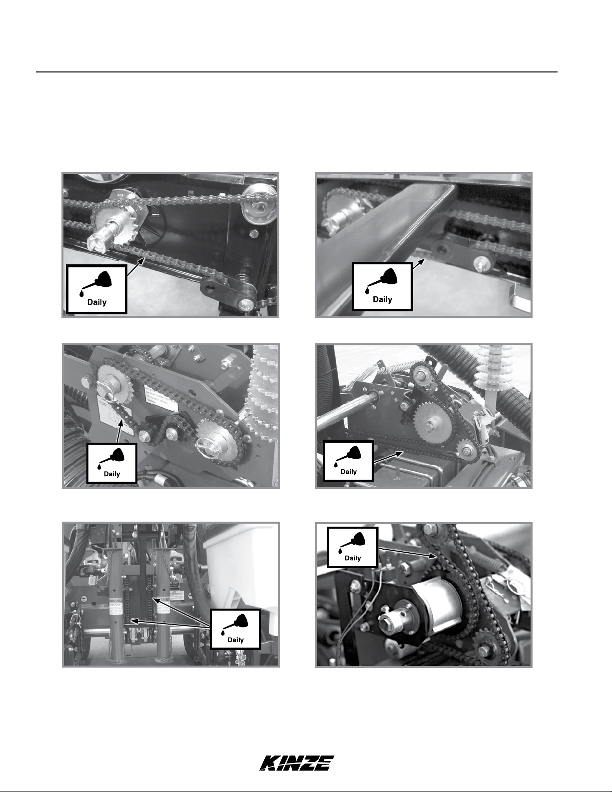
Lubrication and Maintenance
M0256-01Model 3140
DRIVE CHAINS
Lubricate all transmission and drive chains daily with a high quality chain lubricant. Extreme operating conditions such
as dirt, temperature, or speed may require more frequent lubrication. If a chain becomes stiff, it should be removed,
soaked, and washed in solvent to loosen and remove dirt from joints. Soak chain in oil so lubricant can penetrate
between rollers and bushings.
Row Unit Drive Chains (Mechanical Shown) Row Unit Granular Chemical Drive Chains
Seed Rate Transmission Drive Chains
Contact Wheel Drive Chains
(Without Point Row Clutches)
Center Drop Assembly Drive Chains
Contact Wheel Drive Chains
(With Point Row Clutches)
5-2 Rev. 1/18
TM
Page 93

Lubrication and Maintenance
Model 3140M0256-01
Inner Wheel Module Drive Chains
BUSHINGS
Lubricate bushings at frequency indicated.
Check each bolt for proper torque. If bolt is loose, removed it and inspect bushing for cracks and wear. Replace
bushing if necessary. Use only hardened flat washers. Replace damaged flat washers with proper part. Torque
hardware to 130 ft-lb (176.2 N-m).
Pull row unit and/or push row unit parallel
linkages (8 per row)
Row unit “v” closing wheel, covering discs/
single press wheel and/or drag closing wheel
eccentric bushings (2 per row)
Bed leveler parallel linkages (6 per row)
Rev. 1/18 5-3
Contact Wheel Arm (2 Per Wheel Assembly)
TM
Page 94

Lubrication and Maintenance
M0256-01Model 3140
WHEEL BEARINGS
All drive, transport, and marker hub wheel bearings should be repacked annually and checked for wear.
1. Raise wheel off ground.
2. Check for bearing endplay by moving wheel side to side.
3. Rotate wheel to check for bearing roughness. If bearings sound rough, remove hub and inspect bearings.
NOTE: To repack wheel hubs, follow procedure outlined for wheel bearing replacement except bearings and
bearing cups are reused.
GREASE FITTINGS
Parts equipped with grease fittings should be lubricated at frequency indicated with an SAE multipurpose grease.
Clean fitting thoroughly before using grease gun. Frequency of lubrication recommended is based on normal operating
conditions. Severe or unusual conditions may require more frequent attention.
NOTE: Numbers on photo below correspond to photos on following pages showing lubrication frequencies.
12 Row 38" Shown
2. Wing Hinge - 2 Zerks Per Hinge Area1. Row Markers - 4 Zerks Per Assembly On 8
Row 38"/40" And 12 Row 30" Sizes. 2 Zerks
Per Assembly On 12 Row 36"/38", 12 Row
38"/40" And 16 Row 30" Sizes.
5-4 Rev. 1/18
TM
Page 95
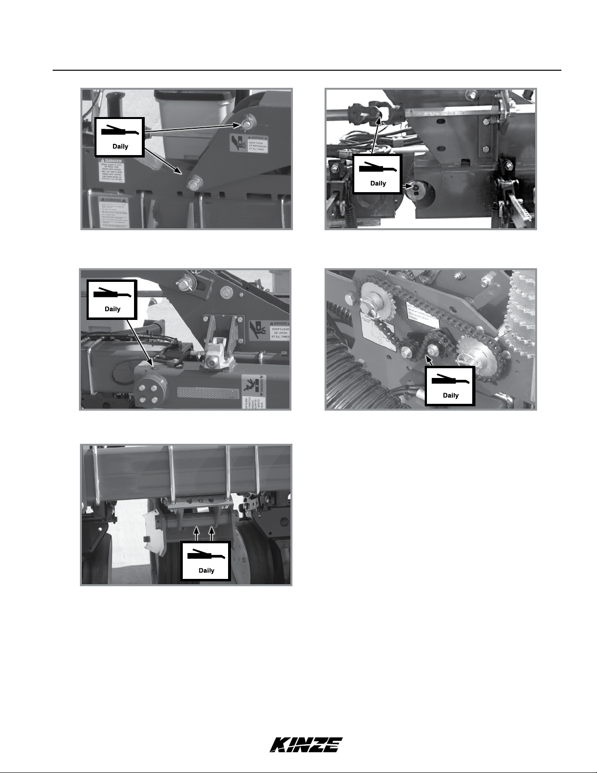
Lubrication and Maintenance
3. Center Hinge - 4 Zerks Per Hinge Area 6. Cam Follower - 1 Zerk Per Cam
7. U-Joint Assembly - 1 Zerk Per Assembly
Model 3140M0256-01
4. Link Assembly - 4 Zerks Per Link 8. Seed Rate Transmission Assemblies - Zerk (Idler)
5. Drive Wheel Arm Pivot - 2 Zerks Per Pivot
Rev. 1/18 5-5
TM
Page 96
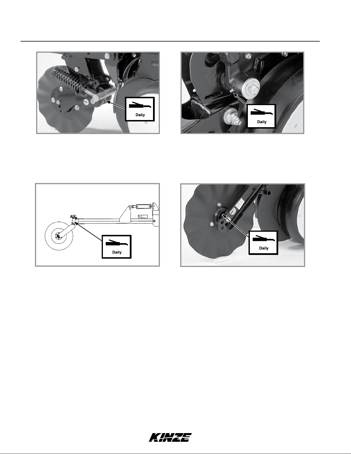
Lubrication and Maintenance
M0256-01Model 3140
Frame mounted Coulter - 1 Per Arm
Lift Assist Arm - 1 Zerk Per Arm
Gauge wheel arms - 1 per arm
(Seals in gauge wheel arm are installed with
lip facing out to allow grease to purge dirt away
from seal. Pump grease into arm until fresh
grease appears between washers and arm.)
(If Applicable) Row Unit Mounted No Till Coulter
Hubs- 1 Zerk Per Hub
(Pump grease into hub until grease comes out
around the seals. Spin hub while filling with
grease.)
5-6 Rev. 1/18
TM
Page 97

Lubrication and Maintenance
Model 3140M0256-01
MOUNTING BOLTS AND HARDWARE
Loose transport wheel lug bolts can
WARNING
NOTICE
result in wheel separation from planter
and result in death, serious injury, and
damage to property and equipment.
Check transport wheel lug nut torque
before operating planter for the first time
and periodically thereafter.
Over-tightening hardware can reduce
its shock load capacity and cause
equipment failure.
Hardware used on Kinze planters are Grade 5 (high strength) unless otherwise noted. Grade 5 cap screws are
marked with three radial lines on the head. Hardware must be replaced with equal size, strength, and thread type.
TORQUE VALUES CHART - PLATED HARDWARE
Grade 2 (No marks) Grade 5 (3 marks)
Grade 8 (6 marks)
Diameter Coarse Fine Coarse Fine Coarse Fine
¼" 50 in-lb 56 in-lb 76 in-lb 87 in-lb 9 ft-lb (12 N-m) 10 ft-lb (14 N-m)
" 8 ft-lb (11 N-m) 9 ft-lb (12 N-m) 13 ft-lb (18 N-m) 14 ft-lb (19 N-m) 18 ft-lb (24 N-m) 20 ft-lb (27 N-m)
" 15 ft-lb (20 N-m) 17 ft-lb (23 N-m) 23 ft-lb (31 N-m) 26 ft-lb (35 N-m) 33 ft-lb (45 N-m) 37 ft-lb (50 N-m)
" 25 ft-lb (34 N-m) 27 ft-lb (37 N-m) 37 ft-lb (50 N-m) 41 ft-lb (56 N-m) 52 ft-lb (71 N-m) 58 ft-lb (79 N-m)
½" 35 ft-lb (48 N-m) 40 ft-lb (54 N-m) 57 ft-lb (77 N-m) 64 ft-lb (87 N-m) 80 ft-lb (108 N-m) 90 ft-lb (122 N-m)
" 50 ft-lb (68 N-m) 60 ft-lb (81 N-m) 80 ft-lb (108 N-m) 90 ft-lb (122 N-m) 115 ft-lb (156 N-m) 130 ft-lb (176 N-m)
" 70 ft-lb (95 N-m) 80 ft-lb (108 N-m) 110 ft-lb (149 N-m) 125 ft-lb (169 N-m) 160 ft-lb (217 N-m) 180 ft-lb (244 N-m)
¾" 130 ft-lb (176 N-m) 145 ft-lb (197 N-m) 200 ft-lb (271 N-m) 220 ft-lb (298 N-m) 280 ft-lb (380 N-m) 315 ft-lb (427 N-m)
" 125 ft-lb (169 N-m) 140 ft-lb (190 N-m) 320 ft-lb (434 N-m) 350 ft-lb (475 N-m) 450 ft-lb (610 N-m) 500 ft-lb (678 N-m)
1" 190 ft-lb (258 N-m) 205 ft-lb (278 N-m) 480 ft-lb (651 N-m) 530 ft-lb (719 N-m) 675 ft-lb (915 N-m)
1" 265 ft-lb (359 N-m) 300 ft-lb (407 N-m) 600 ft-lb (814 N-m) 670 ft-lb (908 N-m)
1¼" 375 ft-lb (508 N-m) 415 ft-lb (563 N-m)
1" 490 ft-lb (664 N-m) 560 ft-lb (759 N-m)
1½" 650 ft-lb (881 N-m) 730 ft-lb (990 N-m)
NOTE: Torque unplated hardware and bolts with lock nuts approximately higher than above values. Torque
bolts lubricated prior to installation to 70% of value shown in chart.
NOTE: Torque Vacuum
fan impeller assembly to
motor shaft "-18 hex
jam nut 50 ft-lb
(67.8 N-m).
SPECIAL TORQUE VALUES & INSTRUCTIONS
Row unit parallel linkage bushing
hardware
/" No till coulter spindle hardware 120 ft-lb (162 Nm)
Ground Drive Tire Lug Bolts 90 ft-lb (122 Nm)
Rev. 1/18 5-7
130 ft-lb (176 Nm)
840 ft-lb (1139 N-m) 930 ft-lb (1261 N-m)
1100 ft-lb (1491 N-m) 1250 ft-lb (1695 N-m) 1780 ft-lb (2413 N-m) 2030 ft-lb (2752 N-m)
1450 ft-lb (1966 N-m) 1650 ft-lb (2237 N-m) 2307 ft-lb (3128 N-m) 2670 ft-lb (3620 N-m)
CYLINDER ROD PISTON RETAINING NUT
Non-Nylock Nut Nylock Nut
½"-20
¾"-16
"-14
1"-14
1"-12
1¼"-12
TM
960 ft-lb (1302 N-m)
1360 ft-lb (1844 N-m) 1500 ft-lb (2034 N-m)
TORQUE CHART
55-70 ft-lb
(75-95 N-m)
115-125 ft-lb
(156-169 N-m)
150-180 ft-lb
(203-244 N-m)
275-330 ft-lb
(373-447 N-m)
300-375 ft-lb
(407-508 N-m)
300-375 ft-lb
(407-508 N-m)
750 ft-lb (1017 N-m)
1075 ft-lb (1458 N-m)
45-55 ft-lb
(61-75 N-m)
100-115 ft-lb
(136-156 N-m)
130-150 ft-lb
(176-203 N-m)
250-275 ft-lb
(339-373 ft-lb)
275-300 ft-lb
(373-407 N-m)
275-300 ft-lb
(373-407 N-m)
Page 98

Lubrication and Maintenance
M0256-01Model 3140
TIRE SERVICING
Explosive separation of rim and tire
WARNING
To prevent tire explosions:
• Maintain proper tire pressure. Inflating a tire above or below the recommended pressure can cause tire damage.
• Mount tires only by properly trained personnel using proper equipment.
• Replace tires with cuts or bubbles. Replace damaged rims. Replace missing lug bolts and nuts.
• Do not weld or heat wheel assembly. Heating increases tire pressure.
parts can cause death or serious injury.
Overinflation, rim and tire servicing,
improper use of rims and tires, or worn
or improperly maintained tires could
result in a tire explosion.
INFLATION SPECIFICATIONS
Overinflation of tires can result in
WARNING
explosive separation of rim and tire and
cause death or serious injury. Different
size rims are designed for different tire
pressures. Inflate to correct pressure for
specific rim size.
MODEL 3140 OPERATING TIRE PRESSURE
Ground Drive/Gauge 7.60" x 15" . . . . . . . . . .40 psi (275.7 kPa)
Contact drive - 4.10" x 6" . . . . . . . . . . . . . . . .50 psi (344.7 kPa)
Contact drive
Transport/ground drive
5-8 Rev. 1/18
TM
Page 99

Lubrication and Maintenance
FINGER PICKUP SEED METER INSPECTION/ADJUSTMENT
Brush attachment
screw
Finger tabs should
Baffle attachment to meter.
Meter attachment to hopper.
contact carrier
plate in this area.
Model 3140M0256-01
Finger tabs should
raise in this area.
Removing meter and baffle
Proper finger operation
1. Remove two thumbscrews and meter from seed hopper and remove three cap screws and baffle from meter
assembly.
2. Rotate seed meter drive by hand to ensure springs are holding tabs of fingers against carrier plat and fingers
raise in correct area as shown in above photo.
Brush
Finger pickup meter parts
Notch in
bearing
housing
Projection
on cam
Spring
Corn Finger Assembly
(Position Spring Opening
Toward Holder)
Oil Sunflower Finger
Assembly
Buildup of debris or chaff may prevent proper finger operation and requires disassembly and cleaning of finger pickup meter.
1. Remove cotter pin, cover nut and adjusting nut and wave washer (If applicable) from drive shaft.
2. Carefully lift finger holder with fingers and cam off shaft and clean.
3. Check brush for wear and replace if necessary or after every 100 acres (41 hectares) per row of operation
(Approximately 800 acres (324 hectares) of corn or sunflowers on a 8 row machine or 1200 acres (486 hectares)
on an 12 row machine).
NOTE: It is not necessary to remove finger holder to replace brush.
4. Remove springs from fingers and remove finger from holder by lifting it out of friction fit slot. Life expectancy of
these parts is about 600-900 acres (243-364 hectares) per row of operation under average conditions.
5. Reassemble meter in reverse order after cleaning and replacing defective parts. Make sure open end of spring
loop is toward inside of finger holder when replacing fingers.
6. Install fingers in holder so holder is flush with carrier plate when assembled. A cam projection aligns with a mating
notch in bearing housing to ensure proper operation when assembled.
Rev. 1/18 5-9
TM
Page 100

Lubrication and Maintenance
7.
Check indentations on carrier plate for wear before installing
finger holder on carrier plate. Excessive wear of carrier plate
at indentations will cause over planting especially with small
sizes of seed. Inspect carrier plate annually. Life expectancy
should be 250-300 acres (100-125 hectares) per row of
operation under average conditions.
8. Install wave washer and adjusting nut with finger holder
flush against carrier. Tighten adjusting nut to fully compress
wave washer. Back off nut ½ to 2 flats to obtain rolling
torque of 22 to 25 inch pounds (2.5 N-m to 2.8 N-m).
M0256-01Model 3140
Indentations
9. Turn finger holder by hand to make sure it is firmly against
carrier plate, but can be rotated with moderate force.
Worn carrier plate
10. Install cover nut and cotter pin. Reinstall baffle.
NOTE: Check adjusting nut tightness on each unit after first day of use and periodically thereafter.
Belt housing cover
Cap screw
Idler mounting bolt
Belt idler
Rotation
Centering belt housing cover
Remove four cap screws around edge of housing cover and nut from belt idler mounting bolt. Paddles must be correctly
oriented as shown above If belt is replaced. A diagram molded into drive sprocket shows correct orientation.
NOTICE
Do not over-tighten hardware or components may be damaged.
Reinstall housing cover. DO NOT TIGHTEN hardware. Wedge a screwdriver between sprocket hub and housing cover
as shown above. Pry cover down until centered on belt housing and tighten hardware. Rotate meter drive shaft and
check idler alignment. Seed belt should “run” centered on idler or with only slight contact with belt housing or cover.
CLEANING FINGER PICKUP SEED METER FOR STORAGE
1. Disassemble meter and blow out any foreign material.
2. Wash ONLY in mild soap and water. Do not use gasoline, kerosene, or any other petroleum based product. Dry
thoroughly.
3. Coat lightly with a rust inhibiter.
4. Rotate finger assembly so finger does not touch brush.
5. Reassemble and store in a dry, rodent-free location.
5-10 Rev. 1/18
TM
 Loading...