

Kinze KPM III User Manual

KPM III ELECTRONIC SEED MONITOR
OPERATOR
MANUAL
M0248 6/13
This manual is applicable to: KPM III Electronic Seed Monitor
Phase 3 Software
Record the serial numbers of your planter control system and the purchase date:
Planter Monitor Serial Number ___________________________________
Date Purchased _______________________________________________
Measured Pulses Per Mile/km
(Radar Distance Sensor) ________________________________________
Measured Pulses Per Mile/km
(Magnetic Distance Sensor) _____________________________________
Kinze® and the Kinze® logo are trademarks owned by Kinze Manufacturing, Inc.


Monitor Operation
KPM III ELECTRONIC SEED MONITOR VER. 3.1
KPM IIIM0248
INTRODUCTION
ESC
KINZE
ACK
NOTE: Refer to IS715 for installation instructions for your KPM III.
The KPM III electronic seed monitor system consists of:
•
A tractor mounted KPM III console powered by tractor 12 VDC battery receives and displays information from planter mounted sensors.
• Seed tube and sensor installed in each planter row unit.
• A magnetic distance sensor installed on planter or a radar distance sensor installed on tractor.
• Shaft rotation sensors (if applicable) installed on planter drill shafts.
• Vacuum, pneumatic down pressure, ASD, and hydraulic level/temperature (If applicable), installed on planter.
• Planter harnesses (junction Y-harness and extension harness where applicable), to which the individual seed tube sensors connect.
The primary harness, which connects the monitor console to the planter harness, is hard-wired into the safety/warning light harness or
control console harness included as standard equipment with the planter.
The KPM III console uses a backlit Liquid Crystal Display (LCD) to show number of monitored rows, relative seed rate for each row (using
bargraph displays), and alarm and warning messages. A continuous audible alarm sounds upon system malfunction or underow conditions
for any monitored row. Alarms must be acknowledged. Various warnings also sound an alarm or ash one or more messages. The LCD
displays row spacing, units (Metric or English), speed (MPH or KM/H), volume, seed population, seed spacing, eld area, and total area.
KPM III software allows simultaneous viewing of seed ow bargraphs for standard and Interplant System rows (up to 36 rows).
The monitor system powers down if there is no new seed ow or operator push key input within one hour.
CONTENTS
Acre Count Mode. . . . . . . . . . . . . . . . . . . . . . . . . . . . . . 16
Adding Even-Row Package
(Front Rows Previously Programmed) ...........10
Adding Interplant Rows
(Rear Rows Previously Programmed Only) ........9
Area Counters ................................25
Area Management. . . . . . . . . . . . . . . . . . . . . . . . . . . . . 24
Changing Volume, Contrast, and Backlighting
with AV Key .................................3
Clearing Field Area ............................26
Conguring Planter Monitor. . . . . . . . . . . . . . . . . . . . . . . 3
General Settings (Programming Interplant condition,
row spacing and units) .......................5
Monitor Key Functions. . . . . . . . . . . . . . . . . . . . . . . . . . . 2
Programming/Connecting Seed Tubes, Shaft Rotation
Sensors, or Radar/Magnetic Distance Sensors ....13
Programming Row Unit Alarm Levels ...............7
Replacing Faulty Sensor(s) . . . . . . . . . . . . . . . . . . . . . . 26
Reprogramming Speed Sensor. . . . . . . . . . . . . . . . . . . 11
Seed Meter Settings ............................6
Speed Sensor Calibration/Programming ............14
Test Mode ...................................17
Warnings and Alarms ..........................21
Data Logging Mode .............................8
Enabling/Disabling Interplant Rows ................17
Field Operation ...............................23
6/13 1
TM
Monitor Operation
M0248 KPM III
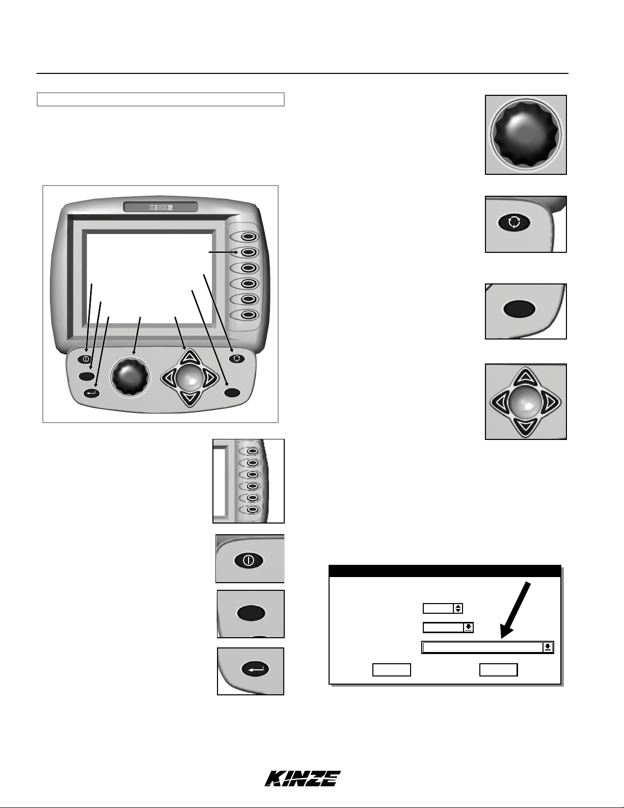
MONITOR KEY FUNCTIONS
Push keys select or change operating mode, active displays,
or the current conguration. Depending on operating mode
or current display selected, some keys may not be active.
Each valid key press is acknowledged by a short beep and an
action is taken. If a key press has no action associated, it is
considered invalid, and there is no feedback.
KINZE
Physical Keys (F1-F6)
Audio/Video Key
On/Off
Escape
Enter
ESC
Rotary
Encoder
Knob
Acknowledge
Arrow Keys
ACK
ROTARY ENCODER KNOB
• Turn knob clockwise to increase or
counterclockwise to decrease value of
item.
• Turn knob clockwise to scroll up or
counterclockwise to scroll down.
• Press knob to enter selection.
AV (AUDIO/VIDEO) KEY
• Set alarm volume.
• Adjust the contrast.
• Adjust backlighting of the LCD display.
Can be used at any time.
ACK (ACKNOWLEDGE) KEY
• Used to silence (acknowledge) the
warning alarm when various error
conditions occur.
NOTE: Alarms can be viewed by
pressing the STATUS key.
ARROW KEYS
• UP arrow key is used to move up.
• DOWN arrow key is used to move
down.
• LEFT arrow key is used to move to the
left.
• RIGHT arrow key is used to move to
the right.
ACK
PHYSICAL KEYS
• Located on R.H. side of console and
referred to as F1, F2, F3, F4, F5 and
F6
• Keys are referenced in descending
order with F1 at the top and F6 at the
bottom.
ON/OFF KEY
• Powers the unit on and off.
ESC KEY
• Used as the CANCEL (escape) key.
ENTER KEY
• Conrms or accepts the highlighted
selection.
ESC
NOTE: Within the LCD, the black box around the smaller
box as shown below indicates which field is selected/
highlighted. Turning the rotary encoder knob or pressing
the UP or DOWN arrow keys moves the black box. When
the black box is positioned on a programmable item, such
as Shaft Sensors, Speed Sensor, Front Row Units or Rear
Row Units, pressing the knob or ENTER key will highlight
the programmable item. A programmable item may only be
changed when it is highlighted.
General Settings
For row spacing enter the smallest spacing between row units
Row Spacing
Units of Measure
Area Counters
15 in
English
Confirm each enable/disable
CancelOK
2 6/13
TM
Status
RowPop
Area
Other
Spacing
90
80
70
60
90
80
70
60
Status
RowPop
Area
Other
Spacing
MPHAvg
Status
RowPop
Area
Spacing
Monitor Operation
KPM IIIM0248
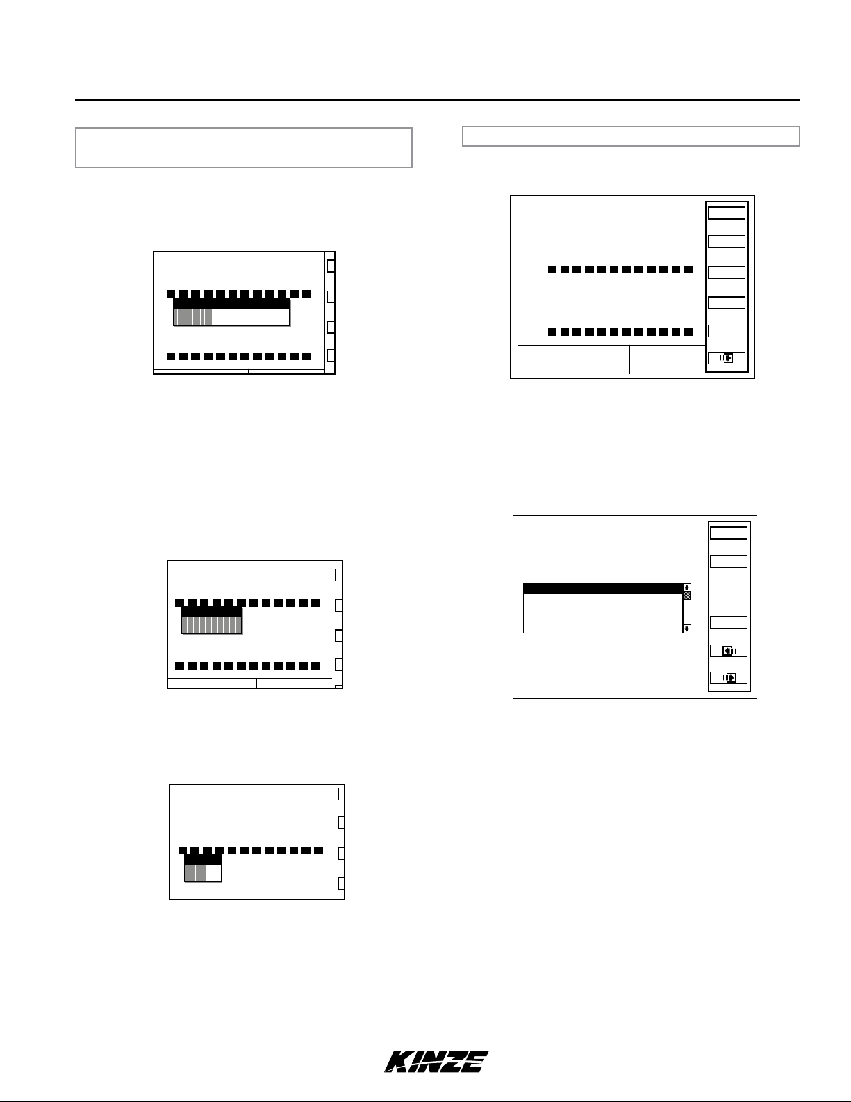
CHANGING VOLUME, CONTRAST, AND BACKLIGHTING
WITH AV KEY
Alarm, volume, LCD screen contrast, and backlighting may be
adjusted at any time, regardless of what is displayed on screen.
STEP 1 Press AV key. Contrast adjustment dialog box
appears in center of display.
%
1 2 3 4 5 6 7 8 9 10 11 12
%
1 2 3 4 5 6 7 8 9 10 11 12
Contrast
STEP 2 Use arrow keys or turn rotary encoder knob to adjust
contrast. Adjustment will be visible on the screen.
STEP 3 To adjust speaker or backlight, go to STEP 4. If
nished press Enter key to save and exit.
STEP 4 Press AV button a second time. The Backlight
adjustment dialog box will appear in center of the
display.
STEP 5 Use arrow keys or turn knob to adjust backlighting.
The effect of the adjustment will be visible on display.
CONFIGURING PLANTER MONITOR
When the KPM III is powered on for the rst time it will go directly
into the Planter Conguration screen (STEP 4).
120
110
100
90
80
70
60
%
1 2 3 4 5 6 7 8 9 10 11 12
120
110
100
90
80
70
60
%
1 2 3 4 5 6 7 8 9 10 11 12
Pop
0 0.0
MPHAvg
RowPop
Spacing
Accuracy
Area
Other
NOTE: Planter Configuration screen displays planter rows
as programmed into KPM III software. The above screen
shows 12 front (Interplant) rows and 12 rear rows. If the KPM
III were programmed for 8 front (Interplant) rows and 8 rear
rows the screen would display 8 front and 8 rear rows.
STEP 1 Press the F6 key until Mode Selection screen
appears.
Kinze Planter Monitor III
Lifetime Area:
0.00
Status
Plant
1. Setup Mode
2. Acre Count Mode
1 2 3 4 5 6 7 8 9 10 11 12
Backlight
1 2 3 4 5 6 7 8 9 10 11 12
3. Disable Interplant (Enabled now)
4. Data logging disabled
5. Test Mode
Please select the operating mode for the
planter monitor or the action to perform.
Effective row spacing: 15.0
About
STEP 6 To adjust speaker go to STEP 7. If nished press
Enter key to save and exit.
NOTE: There are 5 choices on the Mode Selection screen;
1. Setup mode
STEP 7 Press AV button a third time. Speaker adjustment
dialog box will appear in center of display.
2. Acre count mode
3. Disable Interplant (Enabled now) mode
4. Data logging mode
5. Test mode
STEP 2 Select ‘‘1. Setup Mode’’ by turning the rotary encoder
knob or using the arrow keys. Press the knob or
1 2 3 4 5 6 7 8 9 10 11 12
Speaker
Enter key to display the highlighted item.
NOTE: There are 10 choices on the Setup Mode screen;
1. General Settings
2. Seed Meter Settings
STEP 8 Use arrow keys or turn knob to adjust speaker
volume. Volume of sound emitted from speaker
changes as adjustment is made.
STEP 9 Press knob, Enter key or press AV button a fourth
time to save volume, contrast, and backlight settings.
3. Row Unit Alarm Levels
4. Setup Data Logging
5. Configure Planter Monitor
6. Add New Muxbus Sensors
7. Add Single Interplant
®
Row
8. Select Speed Sensor
9. Sensor Setup
10. Calibrate Speed Sensor
6/13 3
TM
Monitor Operation
M0248 KPM III
STEP 3 Select ‘‘5. Congure Planter Monitor’’ by turning the
knob or using the arrow keys. Press the knob or the
Enter key to display the highlighted item.
NOTE: Press F2 key next to Plant any time Plant option is
available to return to Planter Configuration screen.
Setup Mode
Configuration:
1. General Settings
2. Seed Meter Settings
3. Row Unit Alarm Levels
4. Setup Data Logging
5. Configure Planter Monitor
6. Add New Muxbus Sensors
7. Add Single Interplant Row
8. Select Speed Sensor
9. Sensor Setup
10.Calibrate Speed Sensor
Effective row spacing: 15.0
Front / Rear
Status
Plant
Logdata
About
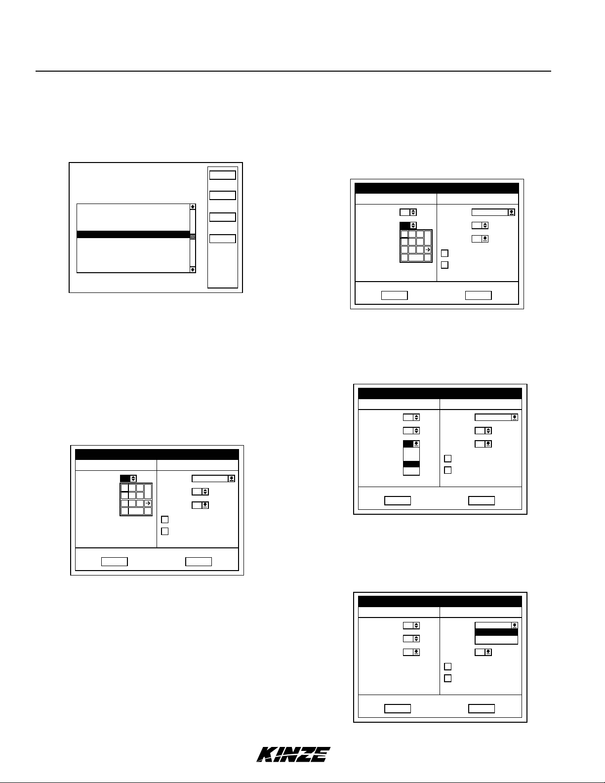
NOTE: Planter monitor cannot be reconfigured while planting.
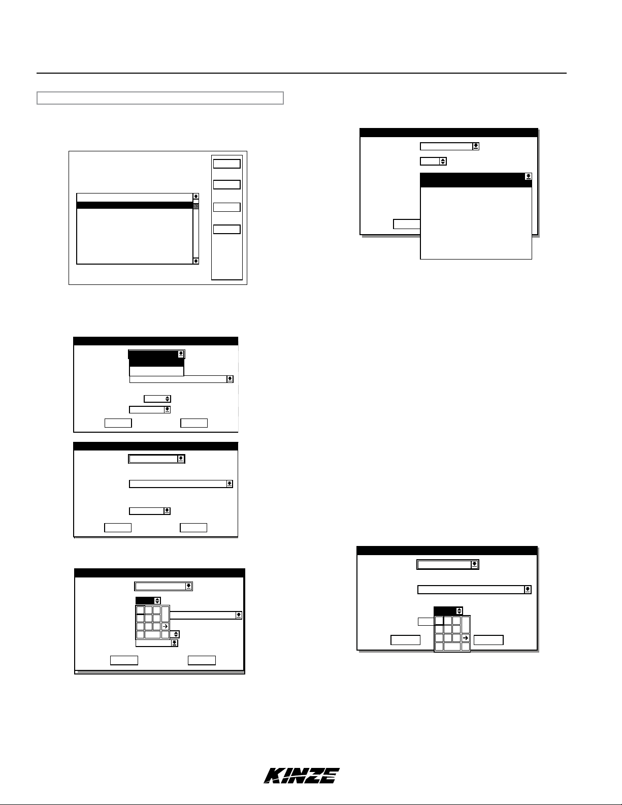
STEP 4
If there are front rows (Interplant) on planter, press
knob or Enter key to highlight “Front Rows” eld. A
drop down number pad appears. Turn knob or use
arrow keys to highlight correct value then press tknob
to select number. For numbers containing more than
one digit select one digit at a time. When desired
quantity is displayed above number pad press Enter
key to return to “Kinze Planter Conguration” screen.
If planter has no front rows turn knob or press arrow
keys to advance to “Rear Rows”.
Kinze Planter Configuration
Planter Type Sensors Installed
Front Rows 0
Rear Rows 12
Shafts 2
There should be one sensor
for each Row and each Shaft.
OK
1 2 3
4 5 6
7 8 9
. 0
0
Speed Radar
C
Vacuum 0
SDS
-
SDS = Seed Delivery System
0
Hydraulic Level/Temp
Downpressure Level
Cancel
STEP 5 Press knob or Enter key to select “Rear Rows” eld.
A drop down number pad appears. Turn knob or use
arrow keys to highlight correct value then press knob
to select number. For numbers containing more than
one digit select one digit at a time. When desired
quantity is displayed above number pad, press
Enter key to return to “Kinze Planter Conguration”
screen.
Kinze Planter Configuration
Planter Type Sensors Installed
Front Rows
Rear Rows
Shafts 2
There should be one sensor
for each Row and each Shaft.
OK
11
0
1 2 3
4 5 6
0
7 8 9
. 0
Speed Radar
Vacuum 0
C
SDS
-
SDS = Seed Delivery System
0
Hydraulic Level/Temp
Downpressure Level
Cancel
STEP 6 Rotate knob or use arrow keys to advance to “Shafts”
eld. Press knob or Enter key to select “Shaft” eld.
A drop down menu appears. Turn knob or use arrow
keys to highlight number of “Shafts”. When correct
value is displayed, press knob or Enter key to return
to “Kinze Planter Conguration” screen.
Kinze Planter Configuration
Planter Type Sensors Installed
Front Rows 11
Rear Rows 12
Shafts 2
There should be one sensor
for each Row and each Shaft.
OK
0
1
2
4
Speed Radar
Vacuum 0
SDS
Hydraulic Level/Temp
Downpressure Level
SDS = Seed Delivery System
0
Cancel
STEP 7 Turn knob or use arrow keys to move to “Speed”
eld. Press knob or Enter key and a drop down
menu displays. Select ‘‘Radar’’ or ‘‘Coil Pick-Up’’
(MDS) by turning knob or using arrow keys. When
desired selection is highlighted press knob or Enter
key.
Kinze Planter Configuration
Planter Type Sensors Installed
Front Rows 11
Rear Rows 12
Shafts 2
There should be one sensor
for each Row and each Shaft.
4 6/13
TM
2
OK
Speed
Vacuum 0
SDS
SDS = Seed Delivery System
Radar
Radar
Coil Pick-Up
0
Hydraulic Level/Temp
Downpressure Level
Cancel
Monitor Operation
KPM IIIM0248
STEP 8 If applicable, turn knob or use arrow keys to advance
to “Vacuum”. Press knob or Enter key and a drop
down menu will appear. Select correct number of
vacuum sensors by turning knob or using arrow
keys. Conrm selection by pressing knob or Enter
key.
STEP 9 If applicable, turn knob or use arrow keys to
advance to “SDS” (Seed Delivery System), Press
knob or Enter key. A drop down menu will appear.
Select correct number of SDS Sensors by turning
knob or using arrow keys. Press knob or Enter key
to conrm selection.
STEP 10 If applicable, turn knob or use arrow keys to advance
to “Hydraulic Level/Temp”. Press knob or Enter key
to select or deselect. When selected, a check mark
will appear in the box.
STEP 11 If applicable, turn knob or use arrow keys to advance
to “Downpressure Level”. Press knob or Enter key to
select or deselect. When selected, a check mark will
appear in the box.
STEP 12 Advance to “OK” by using knob or arrow keys. Press
knob or the Enter key to save information.
Kinze Planter Configuration
Planter Type Sensors Installed
Front Rows 11
Rear Rows 12
Shafts 2
There should be one sensor
for each Row and each Shaft.
OK
Speed Radar
Vacuum 0
SDS
SDS = Seed Delivery System
0
Hydraulic Level/Temp
Downpressure Level
Cancel
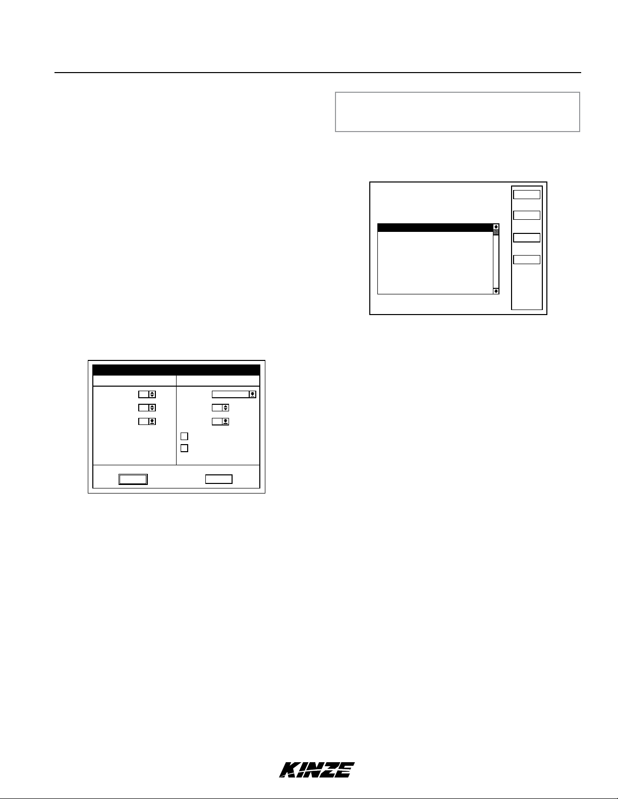
(PROGRAMMING INTERPLANT CONDITION, ROW SPACING
GENERAL SETTINGS
AND UNITS) (METRIC OR ENGLISH)
STEP 1 Turn knob or use arrow keys to highlight “1. General
Settings”. Press knob or Enter key to display highlighted
item.
Setup Mode
Configuration:
1. General Settings
2. Seed Meter Settings
3. Row Unit Alarm Levels
4. Setup Data Logging
5. Configure Planter Monitor
6. Add New Muxbus Sensors
7. Add Single Interplant Row
8. Select Speed Sensor
9. Sensor Setup
10.Calibrate Speed Sensor
Effective row spacing: 15.0
Front / Rear
Status
Plant
Logdata
About
NOTE: When English is selected inches are displayed, if Metric
is selected centimeters are displayed.
STEP 2 Press knob or Enter key to enter correct value for “Row
Spacing”. A drop down number pad will appear. Turn
knob or use arrow keys to highlight rst digit of desired
number and press knob. The number will appear
in “Row Spacing” line. Turn knob or arrow keys to
highlight next digit of number and press knob. Number
will appear in “Row Spacing” line. When correct
number is displayed in “Row Spacing” line, press Enter
key to return to “General Settings” screen.
NOTE: Enter narrowest row spacing planter is equipped to plant
for “Row Spacing”. Example: 12 Row 30 with Interplant, row
spacing would be set to 15.
NOTE: To prevent configuration from being saved select
“Cancel” and press rotary encoder knob or Enter key.
Display will return to “Setup Mode” screen without saving
any changes.
NOTE: When OK is selected monitor automatically advances
to Sensor Setup screen. Sensor Setup can also be selected
from Setup Mode screen. Go to page 6-13 (PROGRAMMING/
CONNECTING SEED TUBES, SHAFT ROTATION SENSORS
AND/OR RADAR/MAGNETIC DISTANCE SENSORS)
STEP 3 Turn knob or use arrow keys to highlight “Units of
Measure” eld. Select “Units of Measure” eld by
pressing knob or Enter key, a drop down menu will
appear. Highlight “English” or “Metric” by turning knob
or using arrow keys. When correct entry is highlighted,
press knob or Enter key to accept unit of measure
entry and return to “General Settings” screen.
STEP 4 Turn knob or use arrow keys to highlight “Area Counters”
eld. Select “Area Counters” eld by pressing knob or
Enter key, a drop down menu will appear. Turn knob
or use arrow keys to highlight “Conrm each enable/
disable”, “Don’t conrm again today”, or “Don’t conrm
enable/disable”. When desired selection is highlighted,
press knob or Enter key to accept selection and return
to “General Settings” screen.
STEP 5 Once correct values are inputed into “General Settings”
screen “OK” button can be selected to save changes,
or “Cancel” button can be selected to discard changes.
Turn knob or use arrow keys to highlight either “OK”
or “Cancel” and press knob or Enter key to return to
“Setup Mode” screen.
6/13 5
TM
Logdata
Seed Meter Settings
Monitor Operation
M0248 KPM III
SEED METER SETTINGS
STEP 1 Scroll to ‘‘2. Seed Meter Settings” by turning rotary
encoder knob or using arrow keys. Press knob or
Enter key to display highlighted item.
Status
Plant
Logdata
About
STEP 2
Setup Mode
Configuration:
1. General Settings
2. Seed Meter Settings
3. Row Unit Alarm Levels
4. Setup Data Logging
5. Configure Planter Monitor
6. Add New Muxbus Sensors
7. Add Single Interplant Row
8. Select Speed Sensor
9. Sensor Setup
10.Calibrate Speed Sensor
Effective row spacing: 15.0
Front / Rear
Select meter type by highlighting “Meter Type” and
pressing knob or Enter key, then highlight “Mechanical”
or “Vacuum” and press knob or enter key.
Seed Meter Settings
Setup Mode
Mechanical
Meter Type
Meter Sprocket
Configuration: Front / Rear
Crop Type
1. General Settings
2. Seed Meter Settings
Seeds per rev
3. Row Unit Alarm Levels
Seed Size
4. Setup Data Logging
5. Configure Planter Monitor
Interplant
6. Add New Muxbus Sensors
7. Add Single Interplant Row
8. Select Speed Sensor
Meter Type
Meter Sprocket
Configuration:
Crop Type
1. General Settings
2. Seed Meter Settings
Seeds per rev
3. Row Unit Alarm Levels
4. Setup Data Logging
Interplant
5. Configure Planter Monitor
6. Add New Muxbus Sensors
7. Add Single Interplant Row
8. Select Speed Sensor
Vacuum
Mechanical
19 teeth
Soybeans
Vacuum
Corn
12
10
Enabled
OK
Seed Meter Settings
Setup Mode
Mechanical
19 teeth
Front / Rear
Corn
12
Enabled
OK
nominal 10, min 0, max 31
Cancel
Cancel
Status
Plant
Logdata
About
Status
Plant
Logdata
About
NOTE: When Mechanical “Meter Type” is selected “Meter
Sprocket” automatically sets.
Setup Mode
OK
Vacuum
28
1 2 3
C
Corn/Popcorn
4 5 6
7 8 9
39
-
10
. 0
Enabled
Meter Type
Meter Sprocket teeth
Configuration: Front / Rear
1. General Settings
Crop Type
2. Seed Meter Settings
Seeds per rev
3. Row Unit Alarm Levels
Seed Size
4. Setup Data Logging
5. Configure Planter Monitor
Interplant
6. Add New Muxbus Sensors
7. Add Single Interplant Row
8. Select Speed Sensor
9. Sensor Setup
nominal 10, min 0, max 31
Cancel
Status
Plant
About
NOTE: When Vacuum “Meter Type” is selected “Meter
Sprocket” automatically defaults to 28 teeth. To change
“Meter Sprocket” select “Meter Sprocket” by turning knob
or using arrow keys. Press knob or enter key, a drop down
number pad displays. Turn knob or use arrow keys to
highlight first digit of desired number and press knob. When
correct number is obtain press knob or enter key.
STEP 3 Turn knob or use arrow keys to highlight “Crop Type”.
Press knob or Enter key to display crop drop down
menu.
Seed Meter Settings
Setup Mode
Meter Type
Meter Sprocket teeth
Configuration: Front / Rear
1. General Settings
Crop Type
Seeds per rev
Seed Size
5. Configure Planter Monitor
Interplant
6. Add New Muxbus Sensors
7. Add Single Interplant Row
8. Select Speed Sensor
9. Sensor Setup
Vacuum
28
Corn/Popcorn
Corn/Popcorn
Low Rate Corn/Popcorn
39
Soybeans
Enabled
High Rate Soybeans
Cotton
Hill Drop Cotton
OK
Milo/Grain Sorghum
Large Dry Edible Beans
Other Large Seed
Other Small Seed
Cancel
Cancel
Status
Plant
Logdata
About
STEP 4 Turn knob or use arrows keys to highlight a crop for
planting then press knob or Enter key. Once crop
type is entered, “Seeds per rev” is automatically set .
A sensitivity threshold (Seed Size) ensures dust and other debris are
ltered out and only actual seeds are counted. Sensitivity threshold is
set to a default for a selected crop which is adequate for most conditions.
Sensitivity can be set between 0 and 31, 0 being most sensitive
(counts smallest particles) and 31 least sensitive (counts large
particles). Adjust threshold one value at a time until desired result
is achieved. Once value is changed it becomes default for that crop.
NOTE: Adjusting threshold too high can cause monitor to
miss seeds and provide inaccurate information. Always
do a ground check to ensure monitor is reading accurately.
STEP 5
Select “Seed Size” and press ENTER key. A
drop down number pad displays.
STEP 6 Turn knob or use arrow keys to highlight rst digit
of desired number. Press knob. When correct
number is obtained, press knob or Enter key.
STEP 7 Turn knob or use arrow keys to highlight “Crop Type”.
Press knob or Enter key to display the crop drop
down menu.
Seed Meter Settings
t
ke
OK
Mechanical
19 teet h
Soybeans
60
v
10
1 2 3
Enabled
4 5 6
7 8 9
39
. 0
nominal 10, min 0, max 31
C
Cancel
-
Meter Type
Meter Sproc
Crop Type
Seeds per re
Seed Size
Interp lant
STEP 8 Turn knob or use arrows keys to highlight a crop
for planting then press knob or Enter key. Once
crop type is entered, the “Seeds per rev” is set
automatically.
6 6/13
TM
Monitor Operation
KPM IIIM0248
STEP 9 (If Applicable) Turn knob or use arrow keys to
highlight “Interplant”. Press knob or Enter key to
display Interplant drop down menu.
Seed Meter Settings
Setup Mode
OK
Vacuum
28
Corn/Popcorn
39
10
Enabled
Enabled
Disabled
Meter Type
Meter Sprocket teeth
Configuration: Front / Rear
1. General Settings
Crop Type
2. Seed Meter Settings
Seeds per rev
3. Row Unit Alarm Levels
Seed Size
4. Setup Data Logging
5. Configure Planter Monitor
Interplant
6. Add New Muxbus Sensors
7. Add Single Interplant Row
8. Select Speed Sensor
9. Sensor Setup
nominal 10, min 0, max 31
Cancel
Status
Plant
Logdata
About
STEP 10 Turn knob or use arrow keys to highlight “enable” or
“disable” and press the knob or Enter key.
STEP 11 When all changes have been made, highlight “OK”
and press knob or Enter key to return to “Setup
Mode” screen.
PROGRAMMING ROW UNIT ALARM LEVELS
Row Unit Alarm Levels allow thresholds for seed rate alarms to
be set. Default is 50% or Average. If average population drops
below 50% for a given row a seed rate alarm is generated for
that row unit. The alarm threshold can be set to 70%, 50%, 0% or
disabled, or any custom percentage for any row.
NOTE: When alarm threshold is disabled for any row no seed
rate alarm will be generated.
Setup Mode
Configuration:
1. General Settings
2. Seed Meter Settings
3. Row Unit Alarm Levels
4. Setup Data Logging
5. Configure Planter Monitor
6. Add New Muxbus Sensors
7. Add Single Interplant Row
8. Select Speed Sensor
9. Sensor Setup
10.Calibrate Speed Sensor
Effective row spacing: 15.0
Front / Rear
Status
Plant
Logdata
About
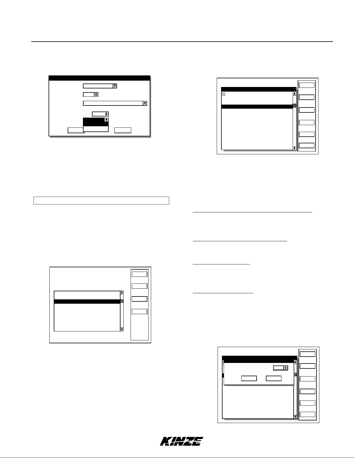
STEP 1 Select ‘‘3. Row Unit Alarm Levels’’ by turning knob or
using arrow keys. Press knob or Enter key to display
highlighted item.
Row Unit Alarm Levels
[Whole Planter]
Rear Row 1 50%
Rear Row 2 50%
Rear Row 3 50%
Rear Row 4 50%
Rear Row 5 50%
Rear Row 6 50%
Rear Row 7 50%
Rear Row 8 50%
Front Row 1 50%
Front Row 2 50%
Front Row 3 50%
Front Row 4 50%
10%
50%
70%
Disable
Other
Done
STEP 2 To set alarm thresholds for whole planter, turn knob
or use arrow keys to highlight “[Whole Planter]” line.
Press key next to desired threshold. When desired
threshold is specied for all row units, press F6 key
next to “Done”.
NOTE: Only configured rows appear on screen.
To set alarm thresholds for all rows in one section, highlight
desired section. Press key next to desired threshold. When
desired threshold is specied for all row units, press F6 key next
to “Done”.
To set alarm thresholds for individual rows, highlight desired row.
Press key next to desired threshold. When desired threshold is
specied for all row units, press F6 key next to “Done”.
To disable row unit alarm, highlight desired section or individual
row. Press F4 key next to “Disable”. When alarm is desired
again highlight disabled section or row. Press key next to desired
threshold.
To enter threshold not listed, highlight desired section or individual
row. Press F5 key next to “Other”. Press knob or Enter key and
a drop down key pad appears. Turn knob or use arrow keys to
highlight rst digit of desired number and press knob. Number
displays in “Enter Alarm Threshold” line. Highlight next digit of
the number and press knob. Number displays in the line. When
correct number is displayed, press Enter key to return to “Set
Alarm Threshold” screen. Turn knob or use arrow keys to advance
to “OK”. Press knob or Enter key to accept threshold levels.
Alarm thresholds can be set for whole planter, any planter section,
or individual rows.
NOTE: A section is a set of rows driven by one or more
shafts, designated to a single shaft sensor.
6/13 7
TM
Row Unit Alarm Levels
[Whole Planter]
Enter Alarm Threshold
Set Alarm Threshold
Rear Row 1 50%
Rear Row 2 50%
Rear Row 3 50%
OK
Rear Row 4 50%
Rear Row 5 50%
Rear Row 6 50%
Rear Row 7 50%
Rear Row 8 50%
Front Row 1 50%
Front Row 2 50%
Front Row 3 50%
Front Row 4 50%
0
Cancel
10%
50%
70%
Disable
Other
Done
 Loading...