

Kinze Grain Carts User Manual
MODEL 900/1100/1300/1500
GRAIN CARTS
OPERATOR MANUAL
M0238-01 Rev. 7/14
Record model number and serial number of your grain cart along with date purchased:
Model Number __________________________________
Serial Number ___________________________________
Date Purchased __________________________________
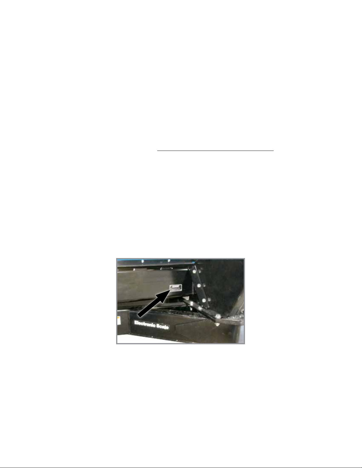
SERIAL NUMBER
Record your serial number and purchase date above for quick reference.
The serial number provides important information about your planter and is required to obtain correct replacement
parts. Always provide planter model and serial number to your Kinze Dealer when ordering parts or anytime
correspondence is made with Kinze Manufacturing, Inc.
Serial number plate location
Kinze® and the Kinze® logo are registered trademarks of Kinze Manufacturing, Inc.
Shur-Co®, LLC is a registered trademark of Shur-Co.
Microsoft® Excel®, and Internet Explorer® are registered trademarks of Microsoft Coroporation.
Grain Tracker™ is a trademark of Digi-Star LLC
All other tradmarks are the property of their respective owners.

Page intentionally blank.

®
Predelivery/Delivery Checklist
Grain CartM0238-01
900-1100-1300-1500 Grain Cart
PREDELIVERY/DELIVERY CHECKLIST
TO THE DEALER
Predelivery service includes assembly, lubrication, adjustment and test. This service ensures cart is delivered to retail
customer/end user ready for field use.
PREDELIVERY CHECKLIST
Use this checklist to inspect cart after it is completely assembled. Check off each item as it is found satisfactory or after
proper adjustment is made.
Wheel nuts torqued to 350 ft-lb (474 N-m).
Tires inflated to specified air pressure. (If Applicable)
All grease fittings lubricated and gearbox oil level checked.
All safety decals and SMV sign are correctly located and legible. Replace if damaged.
SMV decal is in place and shipping cover removed.
Safety/warning lights working properly.
Test run augers. Do not operate tractor PTO above 750 PTO RPM with augers empty.
Check driveline. See “Driveline Inspection” in Operation section.
V-belts aligned and properly tensioned.
Check track alignment. See “Track Alignment” in Maintenance section. (If Applicable)
Safety screens over horizontal auger are in place and properly secured.
Auxiliary safety chains are properly installed and hardware torqued to specification.
Paint all parts scratched in shipment.
This wagon has been thoroughly checked and to the best of my knowledge is ready for delivery to the customer.
(Signature Of Set-Up Person/Dealer Name/Date)
OWNER REGISTER
Name Delivery Date
Street Address Model No. Serial No.
City, State/Province Dealer Name
ZIP/Postal Code Dealer No.
5/12 1

®
Predelivery/Delivery Checklist
M0238-01Grain Cart
DELIVERY CHECKLIST
Check off each item as it is fully explained to retail customer/end user when grain cart is delivered.
Durability and longevity is dependent on regular maintenance as directed in Operator Manual.
Tell retail customer/end user about all safety precautions that must be observed while using this cart.
Advise retail customer/end user of specified tractor requirement for use with this cart.
Along with retail customer/end user check reflective decals and SMV sign are clearly visible with cart attached to
tractor. Check safety/warning lights are in working condition. Tell retail customer/end user to check and follow federal,
state/provincial, and local regulations before towing on a road or highway.
Along retail customer/end user check hitch height when attached to tractor is sufficient to prevent severe bends in PTO
U-joint angles. Check PTO is correct length for making turns and operating on uneven terrain.
Give Operator and Parts Manuals to retail customer/end user and explain all operating adjustments.
Complete Warranty And Delivery Report form.
To the best of my knowledge this machine has been delivered ready for field use and customer has been fully
informed as to proper care and operation.
(Signature Of Delivery Person/Dealer Name/Date)
AFTER DELIVERY CHECKLIST
Suggested items to check during first season of use:
Check cart performance with retail customer/end user.
Review with retail customer/end user importance of proper maintenance and adherence with all safety precautions.
Check for parts that may need to be adjusted or replaced.
Retorque all wheel nuts to 350 ft-lb (474 N-m).
Safety shields and screens are in place.
Safety and reflective decals, and SMV sign are correctly located and decals are legible. Replace if damaged or missing.
Check safety/warning lights are properly installed and working properly.
Check recommended lubrication procedures are being followed.
(Signature Of Follow-Up Person/Dealer Name/Date)
All registrations must be submitted online at “business.kinze.com” within 5 business days of delivery.
Retain a copy of this form for auditing purposes.
Tear Along Perforation
Rev. 7/14
2

Table of Contents
Grain CartM0238-01
OVERVIEW
To the Owner ....................................1-1
Warranty ........................................1-2
General Information ...............................1-2
Introduction. . . . . . . . . . . . . . . . . . . . . . . . . . . . . . . . . . . . . .1-2
Specifications ....................................1-3
General Safety Rules ..............................1-7
Safety Precautions ................................1-7
Safety Signs And Decals ...........................1-8
Safety Instructions, Signs, and Decals. . . . . . . . . . . . . . . . .1-8
OPERATION
Machine Preparation ..............................2-1
Tractor Requirements . . . . . . . . . . . . . . . . . . . . . . . . . . . . . .2-1
Tractor Preparation and Hookup. . . . . . . . . . . . . . . . . . . . . .2-1
Joystick Controls. . . . . . . . . . . . . . . . . . . . . . . . . . . . . . . . . .2-4
Cart Operation ...................................2-4
PTO Torque Limiting/Overrunning Clutch Protection ......2-6
Belt Engagement Indicator . . . . . . . . . . . . . . . . . . . . . . . . . . 2-6
Hydraulic Flow Gate . . . . . . . . . . . . . . . . . . . . . . . . . . . . . . .2-6
Auger Inspection Cover ............................2-7
Grain Tank Clean Out Sweep ........................2-8
Vertical Auger Work Light . . . . . . . . . . . . . . . . . . . . . . . . . . .2-9
Cameras ........................................2-9
Manual and Electric Roll Tarp .......................2-10
Roll Tarp Remote Control Troubleshooting . . . . . . . . . . . . .2-13
Electronic Scale - GT 400. . . . . . . . . . . . . . . . . . . . . . . . . .2-14
Electronic Scale - GT 460. . . . . . . . . . . . . . . . . . . . . . . . . .2-15
Electronic Scale - GT 460 AutoLog ..................2-16
Electronic Scale Printing Options . . . . . . . . . . . . . . . . . . . .2-17
Electronic Scale Troubleshooting ....................2-20
Electronic Scale Troubleshooting ....................2-21
Data Downloader Troubleshooting ...................2-22
LUBRICATION AND MAINTENANCE
Drive Belts and Pulleys. . . . . . . . . . . . . . . . . . . . . . . . . . . . .3-2
Driveline Inspection ..............................3-18
Electronic Scale .................................3-33
Gearbox .......................................3-21
Gearbox Oil Level . . . . . . . . . . . . . . . . . . . . . . . . . . . . . . . . .3-2
Grease Fittings ..................................3-3
Horizontal Auger Bearings ..........................3-1
Horizontal Auger Replacement. . . . . . . . . . . . . . . . . . . . . .3-21
Hydraulic Control Schematic - Manual . . . . . . . . . . . . . . . .3-30
Hydraulic Control Schematic - Remote ...............3-31
Joystick Electrical Schematic .......................3-32
Lower Vertical Auger Replacement ..................3-20
Mounting Bolts and Hardware .......................3-9
Preparation for Storage ...........................3-29
PTO Shaft Coupling ...............................3-2
Row Crop Inside Tire Repair or Removal .............3-24
Splines . . . . . . . . . . . . . . . . . . . . . . . . . . . . . . . . . . . . . . . . .3-1
Tire Servicing ...................................3-11
Torque Values Chart - Plated Hardware ................3-9
Track Alignment .................................3-23
Track Endwheel and Midwheel Bearings ...............3-1
Track Endwheel/Midwheel Bearing Replacement .......3-26
Track Tension ...................................3-22
Upper Vertical Auger Replacement ..................3-19
V-Belt Replacement ..............................3-16
V-Belt Tension Adjustment and Alignment . . . . . . . . . . . . . 3-12
Vertical Auger Counter Balance Valves ...............3-10
Wheel Bearing Replacement .......................3-28
Wheel Bearings ..................................3-1
Wheel Nuts. . . . . . . . . . . . . . . . . . . . . . . . . . . . . . . . . . . . .3-11
Wiring Diagram. . . . . . . . . . . . . . . . . . . . . . . . . . . . . . . . . .3-33
Rev. 4/13 i
TM

This page intentionally blank.

To the Owner
Grain CartM0238-01
Kinze Manufacturing, Inc. thanks you for your patronage. We appreciate your confidence in Kinze farm machinery. Your
Kinze grain cart has been carefully designed to provide dependable operation in return for your investment.
This manual has been prepared to aid you in the operation and maintenance of the grain cart. It should be
considered a permanent part of the machine and remain with the machine when you sell it.
It is the responsibility of the user to read and understand the Operator Manual in regards to safety, operation,
lubrication and maintenance before operation of this equipment. It is the user’s responsibility to inspect and service
the machine routinely as directed in the Operator Manual. We have attempted to cover all areas of safety, operation,
lubrication and maintenance; however, there may be times when special care must be taken to fit your conditions.
Throughout this manual the symbol and the words DANGER, WARNING, and CAUTION are used to call
attention to safety information that if not followed, will or could result in death or injury. NOTICE and NOTE are used to
call your attention to important information. The definition of each of these terms follows:
DANGER Indicates a hazardous situation which, if not avoided, will result in death or serious
injury.
WARNING Indicates a hazardous situation which, if not avoided, could result in death or serious
injury.
CAUTION, used with the safety alert symbol, indicates a hazardous situation which, if not avoided,
could result in minor or moderate injury.
NOTICE is used to address practices not related to personal injury.
NOTE: Special point of information or machine adjustment instructions.
WARNING
Improperly operating or working on this equipment could result in
death or serious injury. Read and follow all instructions in Operator
Manual before operating or working on this equipment.
WARNING
Some photos in this manual may show safety covers, shields, or
lockup devices removed for visual clarity. NEVER OPERATE OR
WORK ON machine without all safety covers, shields, and lockup
devices in place as required.
NOTE: Photos in this manual may be of prototype machines. Production machines may vary in
appearance.
NOTE: Some photos and illustrations in this manual show optional attachments installed. Contact
your Kinze Dealer for purchase of optional attachments.
5/12 1-1
TM
Introduction
M0238-01Grain Cart
Warranty
The Kinze Limited Warranty for your new machine is stated on the retail purchaser’s copy of the Warranty And Delivery
Receipt form. Additional copies of the Limited Warranty can be obtained through your Kinze Dealer.
Warranty, within the warranty period, is provided as part of Kinze’s support program for registered Kinze products
which have been operated and maintained as described in this manual. Evidence of equipment abuse or modification
beyond original factory specifications will void the warranty. Normal maintenance, service and repair is not covered by
Kinze warranty.
To register your Kinze product for warranty, a Warranty And Delivery Receipt form must be completed by the Kinze
Dealer and signed by the retail purchaser, with copies to the Dealer, and to the retail purchaser. Registration must be
completed and submitted to Kinze Manufacturing, Inc. within 5 business days of delivery of the Kinze product to the
retail purchaser. Kinze Manufacturing, Inc. reserves the right to refuse warranty on serial numbered products which
have not been properly registered.
If service or replacement of failed parts which are covered by the Limited Warranty are required, it is the user’s
responsibility to deliver the machine along with the retail purchaser’s copy of the Warranty And Delivery Receipt to
the Kinze Dealer for service. Kinze warranty does not include cost of travel time, mileage, hauling or labor. Any prior
arrangement made between the Dealer and the retail purchaser in which the Dealer agrees to absorb all or part of this
expense should be considered a courtesy to the retail purchaser.
Kinze warranty does not include cost of travel time, mileage, hauling, or labor.
General Information
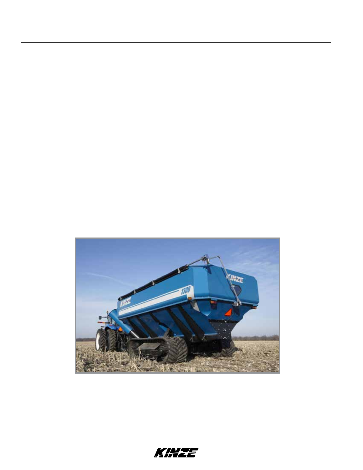
Model 1300 Tracked Corner Auger Grain Cart w/optional electric roll tarp and cameras
Information used in these instructions was current at time of printing. However, due to Kinze’s ongoing product
improvement, production changes may cause your machine to appear slightly different in detail. Kinze Manufacturing,
Inc. reserves the right to change specifications or design without notice and without incurring obligation to install the
same on machines previously manufactured.
Right hand (R.H.) and left hand (L.H.), as used throughout this manual, are determined by facing direction machine
travels in use unless otherwise stated.
1-2 5/12
TM

Specifications
Grain CartM0238-01
900 Grain Cart
Feature Specification
Total Capacity* 900 Bushels
Bushels/Minute - Average* 500 Bushels/minute
Vertical Auger 20" Dia flighting in 23½" Dia. tube; ¼" T edge; " T root flighting. 10° auger position
control. Lower portion of lower vertical auger hard faced flighting.
Bearings - Vertical Auger 2"
Horizontal Auger 20" LH ¼"T edge; " T Root flighting.
Bearings - Horizontal Auger 6-bolt (rear) cast iron hubs with tapered roller bearings, (front) 2" ball bearing.
Gearbox Bevel & spur gear with 2:1 ratio.
Drive Belts Two 4-band, multi-strand V-belts.
Drive Sheaves Eight groove - 7½" drive/15" driven.
PTO - 1000 RPM PTO auger drive with overrunning and torque limiting clutch.
PTO Yoke 1"-21 spline or 1¾"-20 spline.
Spindle Two 4 ½" high alloy.
Hub 20 bolt 13.189 bolt center (2) cast ductile iron.
Safety Chains Two ½" 40,500 lbs rated, grade 70, certified to ASAE S338.5.
Adjustable Discharge Spout Remotely adjustable spout with +/- 14° of up/down motion and fitted with flexible
discharge nozzle.
Tire Size/Pressure 66/43.00-25 (20 Ply) R-1 35 PSI (241 kPa) Min. 40 PSI (275 kPa) Max.
Hydraulic Requirements 5 SCVs (manual) or 2 SCV's (remote) with standard 2320 minimum system psi.
Weight - Empty 21,776 lbs.
Hitch Weight - Empty 3,400 lbs.
Hitch Weight - Loaded 5,000 lbs.
Transport Width 13'-0"
Width - Grain Tank 12'-0"
Length - Grain Tank 18'-6"
Height - Grain Tank 10'-11"
Length - Overall 27'-11
Height - Grain Discharge 13'-2"
* Approximate with 15% moisture corn. Capacity and bushels/minute will vary with moisture content of grain and/or
PTO RPM.
5/12 1-3
TM

Specifications
M0238-01Grain Cart
1100 Grain Cart
Feature Specification
Total Capacity* 1100 Bushels
Bushels/Minute - Average* 750 Bushels/minute
Vertical Auger 22" Dia flighting in 23½" Dia. tube; ¼"T edge; ⁄" T root flighting. 10° auger position
control. Lower portion of lower vertical auger hard faced flighting.
Bearings - Vertical Auger 2"
Horizontal Auger 20" LH ¼"T edge; "T Root flighting.
Bearings - Horizontal Auger 6-bolt (rear) cast iron hubs with tapered roller bearings, (front) 2" ball bearing.
Gearbox Bevel & spur gear with 2:1 ratio.
Drive Belts Two 4-band, multi-strand V-belts.
Drive Sheaves 8 groove - 9¼" drive/18.7" driven.
PTO - 1000 RPM PTO auger drive with overrunning and torque limiting clutch.
PTO Yoke 1¾"-20 spline.
Spindle Four 4½ or two 4½" high alloy.
Hub two 20 bolt or four 10 bolt 13.189 bolt center cast ductile iron.
Safety Chains Two ½" 40,500 lbs rated, grade 70, certified to ASAE S338.5.
Adjustable Discharge Spout Remotely adjustable spout with +/- 14° of up/down motion and fitted with flexible
discharge nozzle.
Hydraulic Requirements 5 SCVs (manual) or 2 SCV's (remote) with standard 2320 minimum system psi.
Flotation Tire Size 1100/45 R46 189 A8 51 PSI (352 kPa) Min. 56 PSI (386 kPa) Max.
Row Crop Tire Size 520/85 R42 165 A8/B 42 PSI (290 kPa) Min. 47 PSI (324 kPa) Max.
Row Crop Tire Adjustment 30" - 40" rows.
Track Width 36"
Track Length 153"
Track End Wheels (Per Track) Two cast iron segmented 36½" diameter.
Track Mid Wheels (Per Track) Eight 16" steel.
* Approximate with 15% moisture corn. Capacity and bushels/minute will vary with moisture content of grain and/or
PTO RPM.
Flotation Tire Row Crop Tracked
Weight - Empty 22,678 lbs. 23,478 lbs. 28,898 lbs.
Hitch Weight - Empty 3,750 lbs. 3,750 lbs. 3,750 lbs.
Hitch Weight - Loaded 6,100 lbs. 6,100 lbs. 6,100 lbs.
Transport Width 13'-0" 12'-7" (30") 15'5" (40") 13'-0"
Width - Grain Tank 12'-0" 12'-0" 12'-0"
Length - Grain Tank 21'-9" 21'-9" 21'-9"
Height - Grain Tank 11'-5" 11'-4" 11'-4"
Length - Overall 31'-7" 31'-7" 31'-7"
Height - Grain Discharge 14'-1" 14'-1" 14'-1"
1-4 5/12
TM

Specifications
Grain CartM0238-01
1300 Grain Cart
Feature Specification
Total Capacity* 1300 Bushels
Bushels/Minute - Average* 750 Bushels/minute
Vertical Auger 22" Dia flighting in 23½" Dia. tube; ¼"T edge; ⁄" T root flighting. 10° auger position
control. Lower portion of lower vertical auger hard faced flighting.
Bearings - Vertical Auger 2"
Horizontal Auger 20" LH ¼"T edge; "T Root flighting.
Bearings - Horizontal Auger 6-bolt (rear) cast iron hubs with tapered roller bearings, (front) 2" ball bearing.
Gearbox Bevel & spur gear with 2:1 ratio.
Drive Belts Two 4-band, multi-strand V-belts.
Drive Sheaves 8 groove - 9¼" drive/18.7" driven.
PTO - 1000 RPM PTO auger drive with overrunning and torque limiting clutch.
PTO Yoke 1¾"-20 spline.
Spindle Four 4½ or two 6" high alloy.
Hub four 10 bolt 13.189 bolt center or two 20 bolt 20" bolt center cast ductile iron.
Safety Chains Two ½" 40,500 lbs rated, grade 70, certified to ASAE S338.5.
Adjustable Discharge Spout Remotely adjustable spout with +/- 14° of up/down motion and fitted with flexible
discharge nozzle.
Hydraulic Requirements 5 SCVs (manual) or 2 SCV's (remote) with standard 2320 minimum system psi.
Flotation Tire Size 1100/45 R46 189 A8 51 PSI (352 kPa) Min. 56 PSI (386 kPa) Max.
Row Crop Tire Size 520/85 R42 165 A8/B 42 PSI (290 kPa) Min. 47 PSI (324 kPa) Max.
Row Crop Tire Adjustment 30" - 40" rows.
Track Width 36"
Track Length Overall 153"
Track Length Contact 108"
Track End Wheels (Per Track) Two cast iron segmented 36½" diameter.
Track Mid Wheels (Per Track) Eight 16" steel.
* Approximate with 15% moisture corn. Capacity and bushels/minute will vary with moisture content of grain and/or
PTO RPM.
Flotation Tire Row Crop Tracked
Weight - Empty 23,580 lbs. 24,380 lbs. 29,800 lbs.
Hitch Weight - Empty 4,200 lbs. 4,200 lbs. 4,200 lbs.
Hitch Weight - Loaded 6,525 lbs. 6,525 lbs. 6,525 lbs.
Transport Width 13'-0" 12'-7" (30") 15'5" (40") 13'-0"
Width - Grain Tank 12'-0" 12'-0" 12'-0"
Length - Grain Tank 25'-1" 25'-1" 25'-1"
Height - Grain Tank 11'-5" 11'-4" 11'-4"
Length - Overall 34'-11" 34'-11" 34'-11"
Height - Grain Discharge 14'-1" 14'-1" 14'-1"
5/12 1-5
TM

Specifications
M0238-01Grain Cart
1500 Grain Cart
Feature Specification
Total Capacity* 1500 Bushels
Bushels/Minute - Average* 750 Bushels/minute
Vertical Auger 22" Dia flighting in 23½" Dia. tube; ¼"T edge; ⁄" T root flighting. 10° auger position
control. Lower portion of lower vertical auger hard faced flighting.
Bearings - Vertical Auger 2"
Horizontal Auger 20" LH ¼"T edge; "T Root flighting.
Bearings - Horizontal Auger 6-bolt (rear) cast iron hubs with tapered roller bearings, (front) 2" ball bearing.
Gearbox Bevel & spur gear with 2:1 ratio.
Drive Belts Two 4-band, multi-strand V-belts.
Drive Sheaves 8 groove - 9¼" drive/18.7" driven.
PTO - 1000 RPM PTO auger drive with overrunning and torque limiting clutch.
PTO Yoke 1¾"-20 spline.
Safety Chains Two ½" 40,500 lbs rated, grade 70, certified to ASAE S338.5.
Adjustable Discharge Spout Remotely adjustable spout with +/- 14° of up/down motion and fitted with flexible
discharge nozzle.
Hydraulic Requirements 5 SCVs (manual) or 2 SCV's (remote) with standard 2320 minimum system psi.
Track Width 36"
Track Length 153"
Track Length Contact 108"
Track End Wheels (Per Track) Two cast iron segmented 36½" diameter.
Track Mid Wheels (Per Track) Eight 16" steel.
Weight - Empty 30,861 lbs.
Hitch Weight - Empty 5,050 lbs.
Hitch Weight - Loaded 7,200 lbs.
Transport Width 13'-0"
Width - Grain Tank 12'-0"
Length - Grain Tank 29'-0"
Height - Grain Tank 11'-4"
Length - Overall 38'-10"
Height - Grain Discharge 14'-1"
* Approximate with 15% moisture corn. Capacity and bushels/minute will vary with moisture content of grain and/or
PTO RPM.
1-6 5/12
TM

General Safety Rules
Safety Precautions
Grain CartM0238-01
1. Read and understand instructions provided in this
manual and warning labels. Review these instructions
frequently!
2. This machine is designed and built with your safety
in mind. Do not make any alterations or changes to this
machine. Any alteration to design or construction may
create safety hazards.
3. A large portion of farm accidents happen from fatigue
or carelessness. Safe and careful operation of tractor and
grain cart will help prevent accidents.
4.
Never allow cart to be operated by anyone unfamiliar
with operation of all functions of the unit. Operators must
read and thoroughly understand all instructions given in
this manual before operating or working on equipment.
5. Be aware of bystanders, particularly children! Always
look around to make sure it is safe to start tow vehicle
engine or move grain cart. This is particularly important
with higher noise levels and quiet cabs, as you may not
hear people shouting.
6. Make sure cart weight does not exceed towing capacity
of tractor, or bridge and road limits. This is critical to
maintain safe control and prevent death or injury, or
property and equipment damage.
7. Never ride or allow others to ride on cart
8. Store cart in an area away from human activity. DO
NOT permit children to play on or around stored unit.
9. Keep hands, feet, and clothing away from moving parts.
Do not wear loose-fitting clothing which may catch in
moving parts.
16. Make sure parked machine is on a hard, level
surface. Wheel chocks may be needed to prevent unit
from rolling.
17. Follow all federal, state/provincial and local
regulations when towing farm equipment on a public
highway. Use safety chain (not an elastic or nylon/
plastic tow strap) to retain connection between towing
and towed machines in the event of primary attaching
system separation.
18. Make sure all safety/warning lights, SMV sign, and
reflective decals are in place and working properly
before transporting machine on public roads.
19. Tow only with farm tractor of a minimum 90 HP. Allow
for unit length when making turns.
20. Track carts should be limited to road use only when
empty and speed to less than 15 MPH.
21. Maintain field drive speeds that are appropriate to
the load condition and field condition.
22. Reduce speed prior to turns to avoid the risk of
overturning. Avoid sudden uphill turns on steep
slopes. Always drive at a safe speed relative to local
conditions and ensure your speed is slow enough for a
safe emergency stop.
23. Always keep the tractor in gear to provide engine
braking when going downhill. Do not coast.
24. Always disengage PTO, shutoff tractor engine and
remove the ignition key before leaving tractor seat,
lubricating or working on grain cart, or when cleaning
out debris.
10. Always wear protective clothing, shoes, gloves, and
hearing and eye protection applicable for the situation.
11. Do not allow anyone to stand between tongue or hitch
and towing vehicle when backing up to cart.
25. Always make sure U-joint yokes are securely locked
on tractor and implement shaft before operating cart.
26. Be especially observant of the operating area and
terrain. Watch for holes, rocks or other hidden hazards.
Always inspect area before operation. DO NOT operate
13. Prevent electrocution, other injuries, or property and
equipment damage. Watch for obstructions such as wires,
tree limbs, etc. when operating machine. Be aware of
clearances during turns and when folding/unfolding grain
near edge of drop-offs or banks, or on steep slopes as
overturn may result. Operate up and down (not across)
intermediate slopes. Avoid sudden starts and stops. Be
extra careful when working on inclines.
chute.
27. Never step across any driveline. Do not attach
14. Pick levelest possible route when transporting across
fields.
drivelines with bolts or pins longer than recommended.
Never operate cart with damaged PTO driveline guards.
15. Never operate grain cart without PTO driveline guards,
tractor master shield and implement shields in place.
Make certain PTO driveline guards turn freely and are
properly attached.
Rev. 4/14 1-7
TM

Safety Instructions, Signs, and Decals
M0238-01Grain Cart
Following are some common hazard warnings associated with this equipment. Pay close attention to all safety,
operating, and maintenance information in this manual and decals applied to your equipment.
DANGER!
Contacting or coming close to power lines or other high energy
sources will cause death or serious injury. Keep away from power
lines or high energy sources at all times.
WARNING
Improperly operating or working on this equipment could result in
death or serious injury. Read and follow all instructions in Operator
Manual before operating or working on this equipment.
WARNING
Contact with rotating PTO shafts can cause death or serious injury.
Stay away from PTO shafts at all times unless clearly disconnected
from power source.
WARNING
Explosive separation of rim and tire parts can cause death or serious
injury.Overination.rimandtireservicing,improperuseofrimsandtires,
or worn or improperly maintained tires could result in a tire explosion.
Safety Signs And Decals
WARNING
Allsafety/warninglights,reectivedecals,andSMVsignmustbe
in place and visible before transporting machine on public roads or
death, serious injury, and damage to property and equipment may
result. Check federal, state/provincial, and local regulations before
transporting equipment on public roads.
Safety signs and decals are placed on the machine to warn of hazards and provide important operating and maintenance
instructions. Information on these signs are for your personal safety and the safety of those around you. FOLLOW ALL
SAFETY INSTRUCTIONS!
• Keepsignscleansotheycanbeeasilyseen.Washwithsoapandwaterorcleaningsolutionasrequired.
• Replacesafetysignsifdamaged,paintedover,ormissing.
• CheckreectivedecalsandSMVsignperiodically.Replaceiftheyshowanylossofofreectiveproperties.
• Whenreplacingdecals,cleanmachinesurfacethoroughlywithsoapandwaterorcleaningsolutionto
remove all dirt and grease.
NOTE: Safety sign and decal locations are shown in the Parts Manual for this machine.
NOTE:StyleandlocationsofSMVsign,reectivedecals,andsafety/warninglightsconformto
ANSI/ASABE S279.14 JUL 2008 and ANSI/ASABE S276.6 JAN 2005.
1-8 5/12
TM
Operation
Grain CartM0238-01
MACHINE PREPARATION
Lubricate grain cart per lubrication information in this manual prior to initial operation and at prescribed intervals. Make
sure all tires are properly inflated or track tension is properly adjusted before each use. Check drive V-belts for proper
tension and alignment. Torque all wheel lug nuts to specified torque.
TRACTOR REQUIREMENTS
Consult your dealer for information on horsepower requirements and tractor compatibility. Two remote SCV’s are
required for remote joystick operation and five SCV’s are required for standard cab operation . A 12 volt DC electrical
system is required on all sizes to operate safety/warning lights, auger-mounted work light, optional electronic scale
system, or electronic roll tarp.
TRACTOR PREPARATION AND HOOKUP
1. Slide tractor drawbar in as far as possible and still allow PTO shaft to have sufficient clearance to prevent damage
to driveline components when making sharp turns and operating over uneven ground.
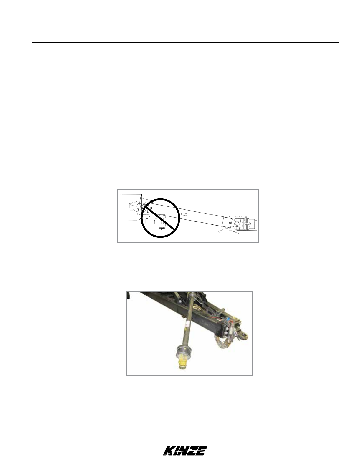
Avoid clevis hitch interference
NOTICE
Clevis hitch (hammer strap style) drawbars may need to be
removed to prevent damage to PTO assembly.
PTO shaft positioned for tractor hookup
NOTICE
Adjust tractor drawbar to prevent severe bends in PTO U-joint
angles and to allow sufficient clearance between tractor drawbar/
hitch pin and PTO shaft.
2. Position PTO as far right of hitch as possible until parking jack is raised.
5/12 2-1
TM
Operation
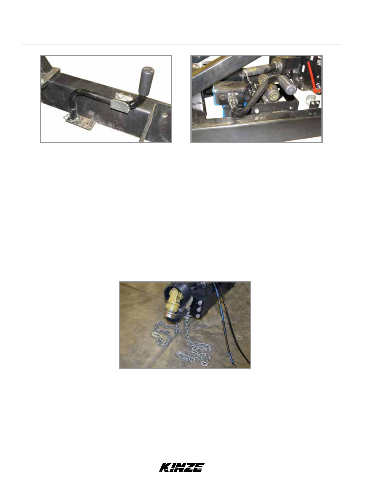
Jack handle stowed Jack handle installed
3. Remove hairpin clip and jack handle from storage location.
4. Install jack handle on jack shaft and raise cart.
NOTICE
Clean and grease PTO shaft coupling each time PTO is installed.
Apply coating of high-speed industrial coupling grease, such
as Chevron® Coupling Grease, that meets AGMA CG-1 and CG-2
standards to extend shaft spline life.
M0238-01Grain Cart
5. Connect cart to tractor hitch. Use a high quality hitch pin of sufficient length and strength and secure pin with a
locking device.
6. Raise jack. Return jack handle to storage location and install hairpin clip.
Safety chains
7. Attach cart PTO connecting yoke to tractor PTO shaft. Spring loaded yoke pin must engage groove in tractor PTO
shaft. Slip tube grease fitting must be visible through hole of outer tube.
8. Transport safety chain must be used to ensure connection is retained between cart and tractor in the event of a
hitch pin/drawbar failure. Torque attaching hardware to 840 ft-lb (1138 N-m).
2-2 5/12
TM

Operation
Grain CartM0238-01
WARNING
Pressurizedhydraulicuidcanpenetratebodytissueandresultin
death, serious infection, or other injuries. Fluid injected under skin
must be IMMEDIATELY removed by a surgeon familiar with this
type of injury. Make sure connections are tight and hoses and
fittings are not damaged before applying system pressure. Leaks
can be invisible. Keep away from suspected leaks. Relieve pressure
before searching for leaks or performing any system maintenance.
NOTICE
Wipe hose ends to remove any dirt before connecting couplers to
tractor ports or contamination may cause equipment failure.
9. Connect hydraulic hoses to tractor. Kinze grain carts require 5 SCV’s for manual operation and two SCV’s for
remote (joystick) operation (can only be used on a closed center system).
Hydraulic Control Settings
Control Hose color Function
SCV1 Red Auger fold
SCV2 Blue Auger tilt/Remote all
SCV3 Yellow Spout tilt
SCV4 Green Horizontal auger
SCV5 White Flow gate
10. Connect seven terminal breakaway connector for the lighting system on cart to seven pin connector on tractor.
If your tractor is not equipped with SAE Standard 7 terminal connector, obtain through your local tractor supply
dealer. Check clearance lights, signal lights, and auxiliary work light are working properly.
11. Connect optional electric roll tarp and camera harnesses. Check for proper operation.
5/12 2-3
TM

JOYSTICK CONTROLS
Operation
M0238-01Grain Cart
Horizontal auger ON
Auger pivot
Joystick top view
Push Yellow trigger to open flow gate.
Pull Red trigger to close flow gate.
Press AUGER ON button to start the horizontal auger. Press
AUGER OFF button to stop horizontal auger.
PIVOT IN/OUT switch moves vertical auger +/- 10° from cart.
SPOUT IN/OUT adjusts “tippy spout” position.
Horizontal auger OFF
Spout adjust
Front
Flow gate open
Flow gate close
Joystick side view
CART OPERATION
WARNING
Contact with rotating PTO shafts can cause death or serious injury.
Stay away from PTO shafts at all times unless clearly disconnected
from power source.
DANGER!
Because of load capacities on bridges and roads and because machine
is not equipped with brakes, this machine is not intended for hauling
loads on public roadways. It is the operator’s responsibility to be
aware of and follow federal, state/provincial and local regulations in
this regard.
DANGER!
Windows provide a limited view behind cart. Use of a rear-view
mirror or optional cart mounted camera is recommended to aid the
operator in seeing behind the cart. Always check carefully, including
blind spots, before backing or turning cart.
WARNING
Wide loads or loads with a high center of gravity may cause instability
or rollover when operating on hillsides or in rough terrain.
WARNING
Do not transport cart with vertical auger extended this can cause
loss of control and could result in death, serious injury, or damage to
porperty and equipment.
2-4 5/12
TM

Operation
DANGER!
Contacting or coming close to power lines or other high energy
sources will cause death or serious injury. Keep away from power
lines or high energy sources at all times.
Unload Grain Cart
NOTICE
Do not operate tractor PTO above 750 PTO RPM with augers empty
or equipment may be damaged.
NOTICE
Roll tarp must be completely open during unloading operations or
suction will damage equipment.
NOTE: Vertical auger tilt must be in fully retracted position to fold/unfold.
1. Open roll tarp completely.
Grain CartM0238-01
2. Unfold vertical auger.
3. Engage PTO at low tractor RPM.
4. Engage horizontal auger.
5. Start to open flow gate and increase tractor RPM.
6. Set grain flow and tractor RPM to desired level.
7. Adjust auger tilt and/or tip spout.
8. Slow tractor RPM as cart reaches empty
9. Close flow gate.
10. Disengage horizontal auger.
11. Allow vertical auger to clean out and disengage PTO.
12. Ensure auger tilt is in full vertical position.
13. Fold auger to storage position.
5/12 2-5
TM
Operation
M0238-01Grain Cart
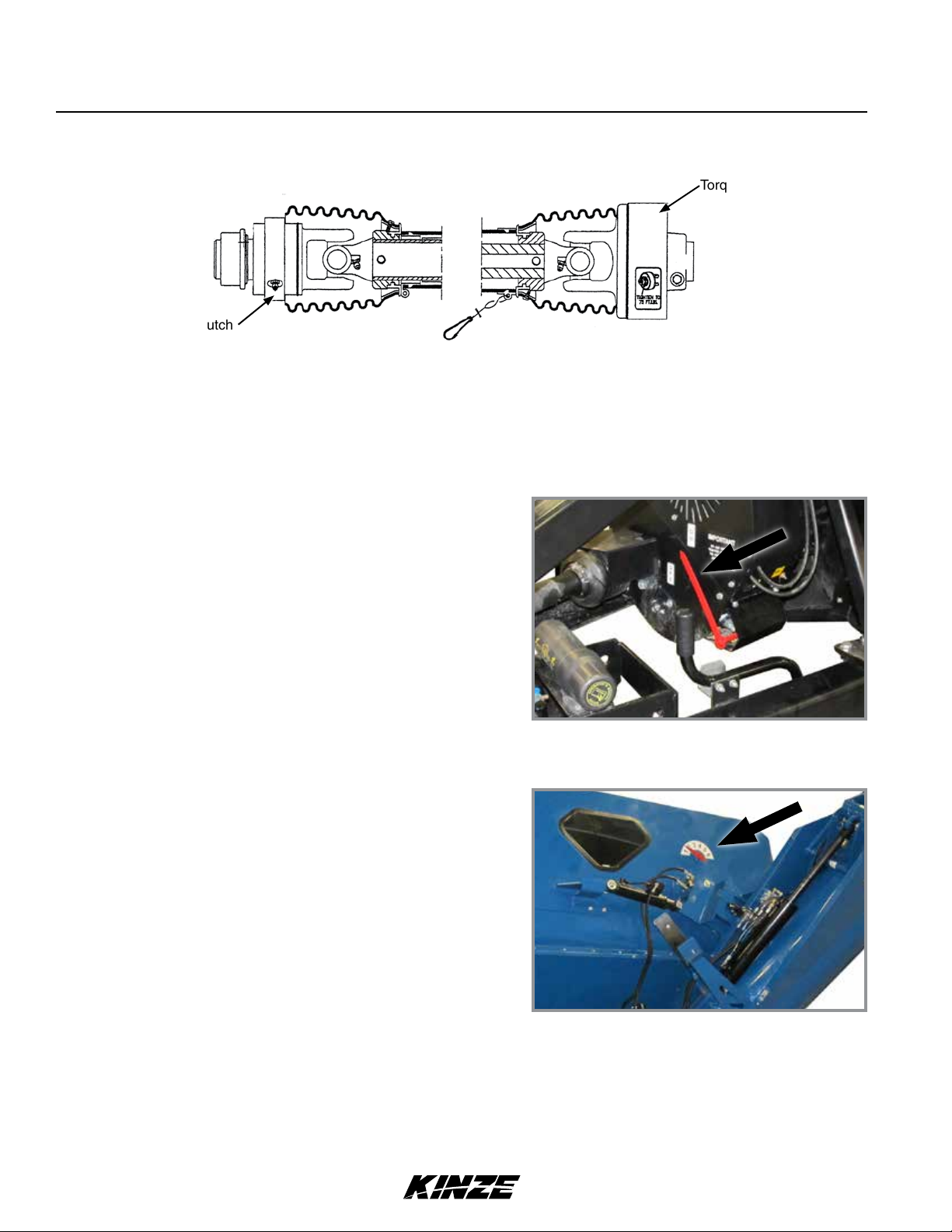
PTO TORQUE LIMITING/OVERRUNNING CLUTCH PROTECTION
Torque limiting clutch
Overrunning clutch
The torque limiting clutch disengages if auger becomes obstructed to prevent driveline and gearbox damage.The torque
limiting clutch resets automatically when PTO RPM is reduced.
The overrunning clutch allows auger system to freewheel and protects tractor and cart from shock damage withPTO
brake-equipped tractors.
BELT ENGAGEMENT INDICATOR
An indicator pointer on front side of belt housing shows if
horizontal auger is engaged (ON) or disengaged (OFF).
indicator should be OFF when PTO is engaged to reduce start up
torque requirements.
As belt tension is disengaged (OFF) you will hear linkage snap
over center and release belt tension.
HYDRAULIC FLOW GATE
Hydraulic flow gate controls volume of grain to horizontal auger.
An indicator on front panel shows position of flow gate.
1. Engage PTO for the vertical auger at low RPM.
2. Engage belt drive clutch to start the horizontal auger.
3. Open gate half way.
4. Adjust flow gate to desired unloading rate.
Belt engagement indicator
Flow gate position indicator
NOTE:Recommendedinitialowgatepositionforriceishalfopen.
2-6 5/12
TM
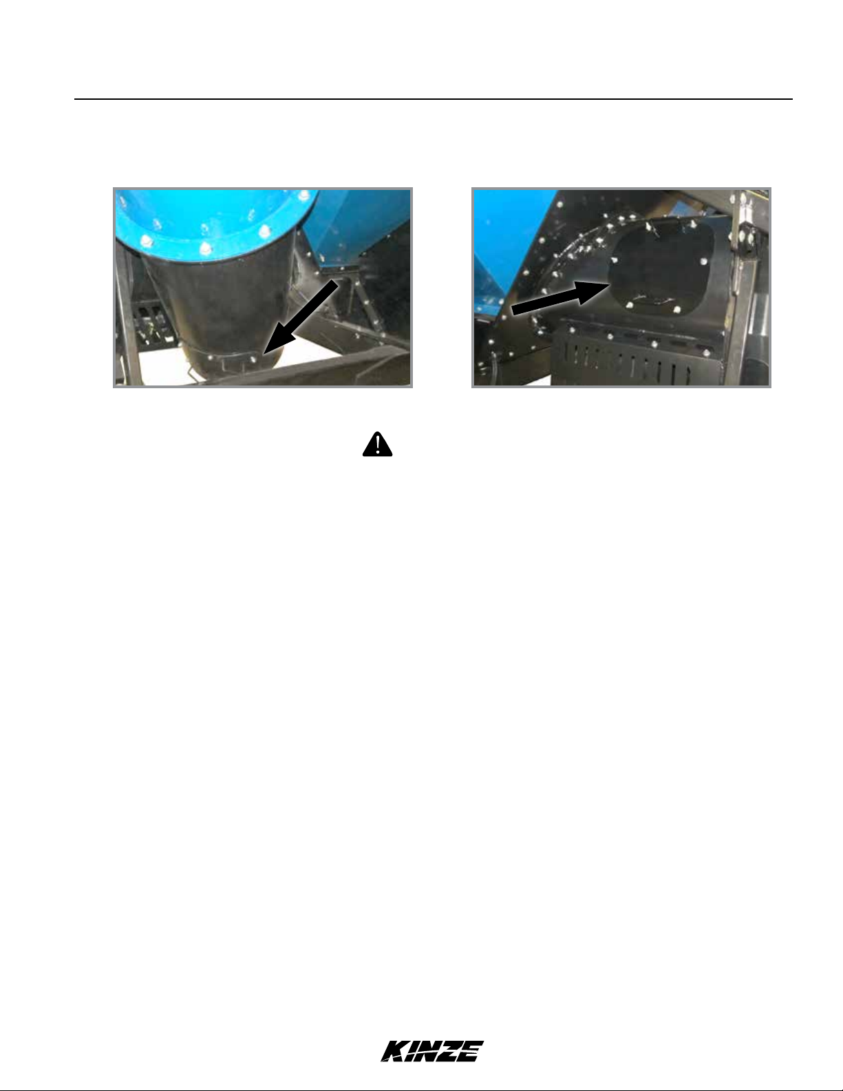
AUGER INSPECTION COVER
Vertical Auger Cleanout door Horizontal Auger Cleanout door
Never open inspection cover while PTO and/or augers are running.
Operation
Grain CartM0238-01
DANGER!
Grain Carts are equipped with two inspection covers one at the bottom of the vertical auger and one located on the grain
transfer that are used for clean out purposes.
The inspection covers should be removed any time total clean out of the wagon is required, such as when changing
crops, to preserve grain identity, or in preparation for storage.
At the end of each season or after extended use, the inspection covers should be removed and the auger chamber
cleaned of all debris and accumulated grain to prevent rust and mold.
Reinstall covers and tighten hardware evenly after clean out is complete.
5/12 2-7
TM
 Loading...