

Kinze 4900 User Manual
MODEL 4900
FRONT FOLD PLANTER
OPERATOR MANUAL
M0247-01 Rev. 5/14
This manual is applicable to: Model 4900 Forward Folding Planters
Record the model number and serial number of your planter along with date purchased:
Model Number ___________________________________
Serial Number ___________________________________
Date Purchased __________________________________
Monitor Serial Number _______________________________________________
Measured Pulses Per Mile/Km (Radar Distance Sensor) ____________________
Measured Pulses Per Mile/ Km (Magnetic Distance Sensor) _________________
4900
SERIAL NUMBER
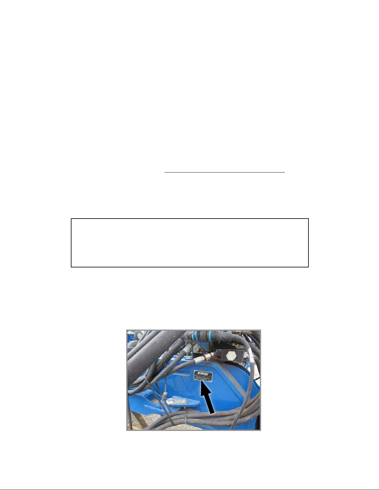
The serial number plate is located on the planter frame as shown below. The serial number provides important information
about your planter and is needed to obtain correct replacement parts. Always provide model number and serial number
to your Kinze Dealer when ordering parts or when contacting Kinze Manufacturing, Inc.
Serial Number Plate Location
Kinze® and the Kinze® logo are registered trademarks of Kinze Manufacturing, Inc.
Vacuum Meter, Electric Drive, and Flip Axle have patents pending.

This page intentionally left blank.

Predelivery/Delivery Checklist
Model 4900M0247-01
TO THE DEALER
Predelivery service includes assembly, lubrication, adjustment and test. This service helps ensure planter is delivered
to retail customer/end user ready for field use.
PREDELIVERY CHECKLIST
Use the following checklist after planter is completely assembled. Check off each item as it is found satisfactory or after
proper adjustment is made.
Row units properly spaced and optional attachments correctly assembled.
Row marker assemblies installed and adjusted at each end of the planter.
Vacuum meter and bulk fill components properly installed (as applicable).
All grease fittings in place and lubricated.
All working parts move freely, bolts are tight, and cotter pins are spread.
Check all drive chains for proper tension and alignment.
Check for oil leaks and proper hydraulic operation.
Hydraulic hoses correctly routed to prevent damage.
Inflate tires to specified air pressure and torque wheel lug bolts and lug nuts as specified in the Operator Manual.
All safety decals correctly located and legible. Replace if damaged.
All reflective decals and SMV sign correctly located and visible when the planter is in transport position.
Safety/warning lights correctly installed and working properly.
Paint all parts scratched during shipment or assembly.
All safety lockup devices on the planter and correctly located.
Auxiliary safety chain properly installed and hardware torqued to specification.
Vacuum fan PTO-driven pump correctly attached to tractor. Oil reservoir filled to capacity and system inspected for
leaks (If applicable).
Planter has been thoroughly checked and to the best of my knowledge is ready for delivery to the customer.
(Signature of Set-Up Person/Dealer Name/Date)
OWNER REGISTER
Name Delivery Date
Street Address Model No. 4900 Serial No.
City, State/Province Dealer Name
ZIP/Postal Code Dealer No.
Rev. 3/14
TM

Predelivery/Delivery Checklist
M0247-01Model 4900
DELIVERY CHECKLIST
Use the following checklist at time planter is delivered as a reminder of very important information which should be
conveyed to retail customer/end user. Check off each item as it is fully explained.
Check proper operation of vacuum fan, bulk fill fan, and PTO-driven pump (If applicable) with tractor used with planter.
Life expectancy of this or any other machine is dependent on regular lubrication as directed in the Operator Manual.
All applicable safety precautions.
Along with retail customer/end user, check reflective decals and SMV sign are clearly visible with planter in transport
position and attached to tractor. Check safety/warning lights are in working condition. Tell retail customer/end user
to check federal, state/provincial, and local regulations before towing or transporting on a road or highway.
Give Operator Manual, Parts Manual, and all Instruction Sheets to retail customer/end user and explain all operating
adjustments.
Read warranty to retail customer/end user.
Complete Warranty and Delivery Report form.
To the best of my knowledge this machine has been delivered ready for field use and customer has been fully
informed as to proper care and operation.
(Signature of Delivery Person/Dealer Name/Date)
AFTER DELIVERY CHECKLIST
The following is a list of items we suggest to check during the first season of use of the equipment.
Check planter performance with retail customer/end user.
Check performance of vacuum meter or mechanical seed metering system with retail customer/end user.
Review importance of proper maintenance and adherence to all safety precautions with retail customer/end user.
Check for parts that may need to be adjusted or replaced.
Check all safety decals, reflective decals, and SMV sign are correctly located as shown in the Parts Manual and that
decals are legible. Replace if damaged or missing.
Check safety/warning lights are working properly.
(Signature of Follow-Up Person/Dealer Name/Date)
All registrations must be submitted online at “business.kinze.com” within 5 business days of delivery.
Retain a copy of this form for auditing purposes.
Tear Along Perforation
Rev. 4/14
TM

Table of Contents
Model 4900M0247-01
OVERVIEW
To The Owner ..................................1-1
Warranty ......................................1-2
General Information . . . . . . . . . . . . . . . . . . . . . . . . . . . . . . 1-2
Specifications. . . . . . . . . . . . . . . . . . . . . . . . . . . . . . . . . . . 1-3
General Safety Rules. . . . . . . . . . . . . . . . . . . . . . . . . . . . . 1-5
Safety Signs And Decals . . . . . . . . . . . . . . . . . . . . . . . . . .1-6
Safety Precautions. . . . . . . . . . . . . . . . . . . . . . . . . . . . . . . 1-6
MACHINE OPERATION
Row Marker Safety Lockup ........................2-1
Drawbar Hitch Lockup (Option) .....................2-2
2-Point Hitch Option. . . . . . . . . . . . . . . . . . . . . . . . . . . . . . 2-2
Initial Planter Preparation. . . . . . . . . . . . . . . . . . . . . . . . . . 2-3
Tractor Requirements. . . . . . . . . . . . . . . . . . . . . . . . . . . . . 2-4
Vacuum Meter Tractor Mounted PTO Pump and Planter
Mounted Hydraulics ............................2-4
Tractor Preparation and Hookup ....................2-5
Transporting Planter. . . . . . . . . . . . . . . . . . . . . . . . . . . . . . 2-7
Level Planter ...................................2-8
Jump Start Sensor . . . . . . . . . . . . . . . . . . . . . . . . . . . . . . . 2-9
Field Operation .................................2-9
Transport to Field Sequence using isobus. . . . . . . . . . . . 2-10
Transport to Field Sequence USING CONTROL BOX 2-16
Field to Transport Sequence USING ISOBUS . . . . . . . . . 2-22
Field to Transport Sequence Using Control Box .......2-28
Row Marker Operation ...........................2-34
Row Marker Speed Adjustment . . . . . . . . . . . . . . . . . . . . 2-35
Row Marker Cable Adjustment ....................2-36
Row Marker Length And Disc Blade Adjustment .......2-37
Vacuum Meter System ...........................2-38
Analog Vacuum or Pressure Gauge. . . . . . . . . . . . . . . . . 2-38
Bulk Fill System . . . . . . . . . . . . . . . . . . . . . . . . . . . . . . . .2-39
Bulk fill Entrainer Access . . . . . . . . . . . . . . . . . . . . . . . . .2-40
Bulk Fill Tanks - Clean Out. . . . . . . . . . . . . . . . . . . . . . . . 2-41
Bulk Fill Scale Package Option ....................2-41
Monitor Seed Levels ............................2-42
Master Module . . . . . . . . . . . . . . . . . . . . . . . . . . . . . . . . . 2-43
Field Test .....................................2-44
Field Check Seed Population. . . . . . . . . . . . . . . . . . . . . . 2-44
Determining Pounds Per Acre . . . . . . . . . . . . . . . . . . . . .2-45
Determining Bushels Per Acre. . . . . . . . . . . . . . . . . . . . . 2-45
Field Check Granular Chemical Application ..........2-46
ROW UNIT OPERATION
Planting Depth . . . . . . . . . . . . . . . . . . . . . . . . . . . . . . . . . .3-1
“V” Closing Wheel Adjustment (Rubber or Cast Iron) ....3-1
Closing Wheel Shield (Rubber or Cast Iron
“V” Closing Wheels) ............................3-1
Covering Discs/Single Press Wheel Adjustment ........3-2
Seed Hoppers ..................................3-3
Quick Adjustable Down Force Springs Option . . . . . . . . . . 3-4
Pneumatic Down Pressure ........................3-5
Temperature Sensor Option ........................3-5
Field Operation .................................3-6
Manual Run Button ..............................3-6
Vacuum Settings ................................3-7
Seed Meter Cleanout. . . . . . . . . . . . . . . . . . . . . . . . . . . . 3-10
Additives .....................................3-11
Row Unit Mounted No Till Coulter ..................3-12
Coulter Mounted Residue Wheels . . . . . . . . . . . . . . . . . . 3-12
Granular Chemical Hopper and Drive ...............3-13
Granular Chemical Banding Options . . . . . . . . . . . . . . . .3-14
FERTILIZER ..............................4-1
Notched Single Disc Openers ......................4-1
Knife Adjustment ................................4-2
Gauge Wheel Depth Adjustment ....................4-3
Liquid Fertilizer Attachment ........................4-4
Check Valves . . . . . . . . . . . . . . . . . . . . . . . . . . . . . . . . . . . 4-4
Piston Pump ...................................4-5
Rear Trailer Hitch Option ..........................4-6
RATE CHARTS . . . . . . . . . . . . . . . . . . . . . . . . . . . . 5-1
General Planting Rate Information. . . . . . . . . . . . . . . . . . . 5-1
Centrifugal Pump fertilizer Rates ....................5-3
LUBRICATION AND MAINTENANCE
Lubrication . . . . . . . . . . . . . . . . . . . . . . . . . . . . . . . . . . . . .6-1
Lubrication Symbols .............................6-1
Wheel Bearings . . . . . . . . . . . . . . . . . . . . . . . . . . . . . . . . . 6-1
Grease Fittings .................................6-2
PTO Shaft Coupling. . . . . . . . . . . . . . . . . . . . . . . . . . . . . . 6-8
Liquid Fertilizer Piston Pump Crankcase Oil Level ......6-8
Liquid Fertilizer Centrifugal Pump ...................6-8
Mounting Bolts and Hardware ......................6-9
Tire Pressure . . . . . . . . . . . . . . . . . . . . . . . . . . . . . . . . . .6-10
Transport Tires . . . . . . . . . . . . . . . . . . . . . . . . . . . . . . . . . 6-10
Inflation Specifications ...........................6-10
Vacuum Seed Meter Maintenance. . . . . . . . . . . . . . . . . . 6-11
Vacuum Seed Meter Cleanout. . . . . . . . . . . . . . . . . . . . . 6-11
Rev. 5/14 i
TM

M0247-01Model 4900
Gauge Wheel Adjustment ........................6-12
Gauge Wheel Arm Pivot Spindle Replacement . . . . . . . . 6-12
Gauge Wheel Arm Bushing/Seal Replacement. . . . . . . . 6-13
15" Seed Opener Disc Blade/Bearing Assembly .......6-14
Seed Tube Guard/Inner Scraper ...................6-15
Row Unit Mounted No Till Coulter ..................6-16
Coulter or Row Unit Mounted Residue Wheels . . . . . . . .6-16
Tractor Mounted Pump Drive and Oil Cooler . . . . . . . . . .6-17
Check Valve ...................................6-18
Flow Control Valves . . . . . . . . . . . . . . . . . . . . . . . . . . . . . 6-18
Pressure Relief Valves ...........................6-18
Pressure Compensated Flow Control Valves. . . . . . . . . . 6-18
Solenoid Valve . . . . . . . . . . . . . . . . . . . . . . . . . . . . . . . . . 6-19
Row Marker Bearing Lubrication or Replacement . . . . . . 6-20
Transport and Lift/Ground Drive Wheel Bearing
Repack or Replacement .......................6-21
Fertilizer Check Valve Cleaning and Repair ...........6-22
Piston Pump Storage. . . . . . . . . . . . . . . . . . . . . . . . . . . . 6-22
Centrifugal Pump Storage . . . . . . . . . . . . . . . . . . . . . . . . 6-22
Preparation for Storage ..........................6-23
Electrical Wiring Diagram. . . . . . . . . . . . . . . . . . . . . . . . . 6-24
Base Machine Options Wiring Diagram. . . . . . . . . . . . . . 6-25
Row Unit Harness Diagram .......................6-26
Electrical Control Console Schematic ...............6-27
ISO Extension Cable ............................6-28
Drawbar Hitch Cable ............................6-28
Lights Cable ...................................6-29
ISO Planter Cable ..............................6-29
Right Auxiliary Cable ............................6-30
Left Auxiliary Cable .............................6-31
CAN Power Cable ..............................6-32
Row Unit Cable LIN . . . . . . . . . . . . . . . . . . . . . . . . . . . . .6-33
Insecticide Motor Cable . . . . . . . . . . . . . . . . . . . . . . . . . .6-33
Insecticide Communication Cable ..................6-34
Motor Cable ...................................6-34
Fertilizer Control Cable ..........................6-35
Fertilizer Option Cable ...........................6-36
Temperature Sensor Cable .......................6-36
Hydraulic Schematic (Planter Raising) ..............6-38
Hydraulic Schematic (Options) ....................6-40
Hydraulic Valve Block Functions ...................6-42
TROUBLESHOOTING
Bulk fill ........................................7-1
Closing Wheel ..................................7-1
Piston Pump ...................................7-2
PTO Pump Drive and Oil Cooler Option ..............7-3
Row Marker Operation ............................7-4
Vacuum Seed Meter .............................7-5
Solenoid Valve . . . . . . . . . . . . . . . . . . . . . . . . . . . . . . . . . . 7-7
ii Rev. 5/14
TM

To The Owner
M0247-01Model 4900
Kinze Manufacturing, Inc. thanks you for your patronage. We appreciate your confidence in Kinze farm machinery. Your
Kinze planter has been carefully designed to provide dependable operation in return for your investment.
This manual has been prepared to aid you in the operation and maintenance of the planter. It should be
considered a permanent part of the machine and remain with the machine when you sell it.
It is the responsibility of the user to read and understand the Operator Manual in regards to safety, operation,
lubrication and maintenance before operation of this equipment. It is the user’s responsibility to inspect and service
the machine routinely as directed in the Operator Manual. We have attempted to cover all areas of safety, operation,
lubrication and maintenance; however, there may be times when special care must be taken to fit your conditions.
Throughout this manual the symbol and the words DANGER, WARNING, and CAUTION are used to call
attention to safety information that if not followed, will or could result in death or injury. NOTICE and NOTE are used to
call your attention to important information. The definition of each of these terms follows:
DANGER Indicates a hazardous situation which, if not avoided, will result in death or serious
injury.
WARNING Indicates a hazardous situation which, if not avoided, could result in death or serious
injury.
CAUTION, used with the safety alert symbol, indicates a hazardous situation which, if not avoided,
could result in minor or moderate injury.
NOTICE is used to address practices not related to personal injury.
NOTE: Special point of information or machine adjustment instructions.
WARNING
Improperly operating or working on this equipment could result in
death or serious injury. Read and follow all instructions in Operator
Manual before operating or working on this equipment.
WARNING
Some photos in this manual may show safety covers, shields, or
lockup devices removed for visual clarity. NEVER OPERATE OR
WORK ON machine without all safety covers, shields, and lockup
devices in place as required.
NOTE: Do not start the power pack (alternator) until the Kinze planter screens are loaded up on the ISOBUS
display.
NOTE: Photos in this manual may be of prototype machines. Production machines may vary in appearance.
NOTE: Some photos and illustrations in this manual show optional attachments installed. Contact your Kinze
Dealer for purchase of optional attachments.
1-1 Rev. 5/14
TM
Overview
M0247-01Model 4900
WARRANTY
The Kinze Limited Warranty for your new machine is stated on the retail purchaser’s copy of the Warranty And Delivery
Receipt form. Additional copies of the Limited Warranty can be obtained through your Kinze Dealer.
Warranty, within the warranty period, is provided as part of Kinze’s support program for registered Kinze products
which have been operated and maintained as described in this manual. Evidence of equipment abuse or modification
beyond original factory specifications will void the warranty. Normal maintenance, service and repair is not covered by
Kinze warranty.
To register your Kinze product for warranty, a Warranty And Delivery Receipt form must be completed by the Kinze
Dealer and signed by the retail purchaser, with copies to the Dealer, and to the retail purchaser. Registration must be
completed and submitted to Kinze Manufacturing, Inc. within 5 business days of delivery of the Kinze product to the
retail purchaser. Kinze Manufacturing, Inc. reserves the right to refuse warranty on serial numbered products which
have not been properly registered.
If service or replacement of failed parts which are covered by the Limited Warranty are required, it is the user’s
responsibility to deliver the machine along with the retail purchaser’s copy of the Warranty And Delivery Receipt
to the Kinze Dealer for service. Kinze warranty does not include cost of travel time, mileage or hauling. Any prior
arrangement made between the Dealer and the retail purchaser in which the Dealer agrees to absorb all or part of this
expense should be considered a courtesy to the retail purchaser.
Kinze warranty does not include cost of travel time, mileage, hauling, or labor.
GENERAL INFORMATION
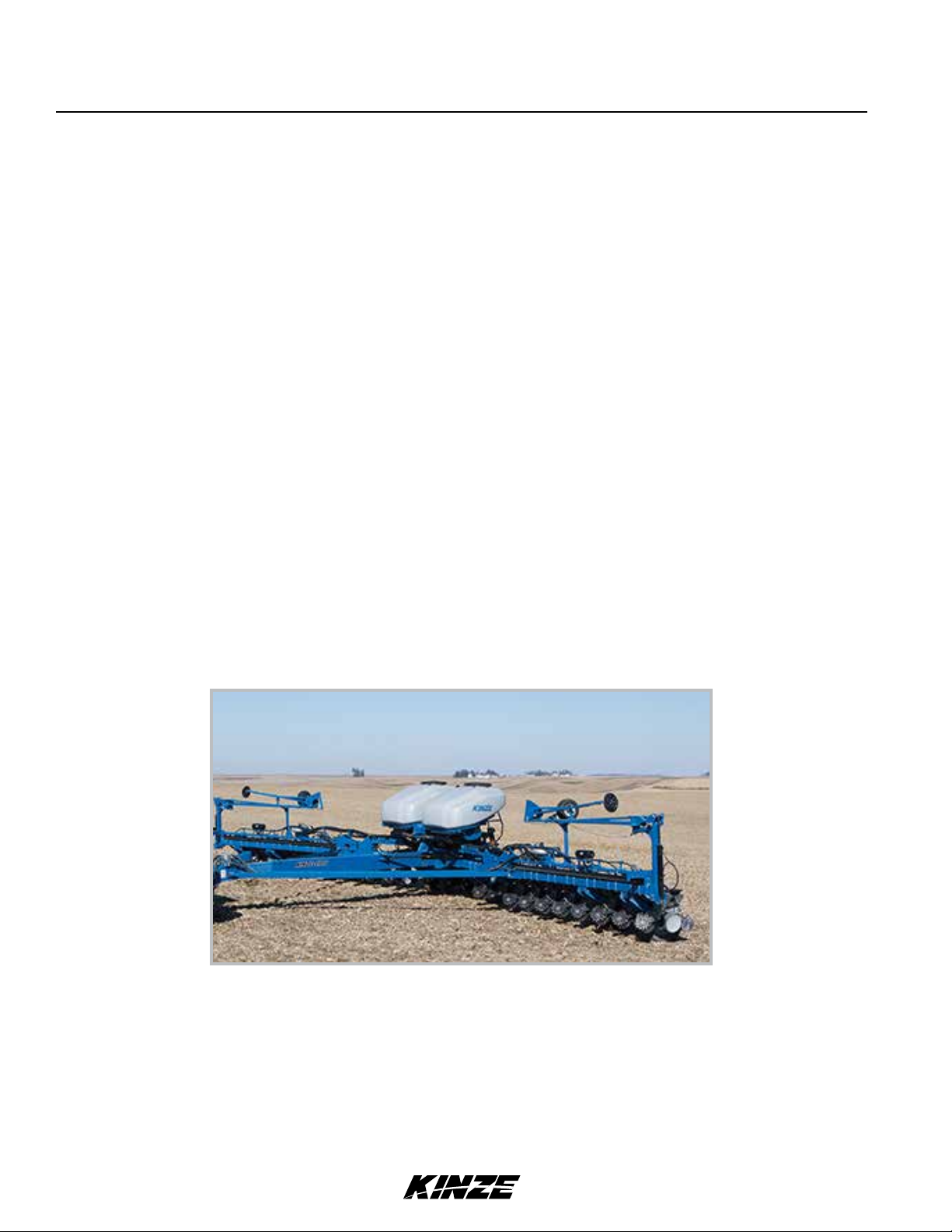
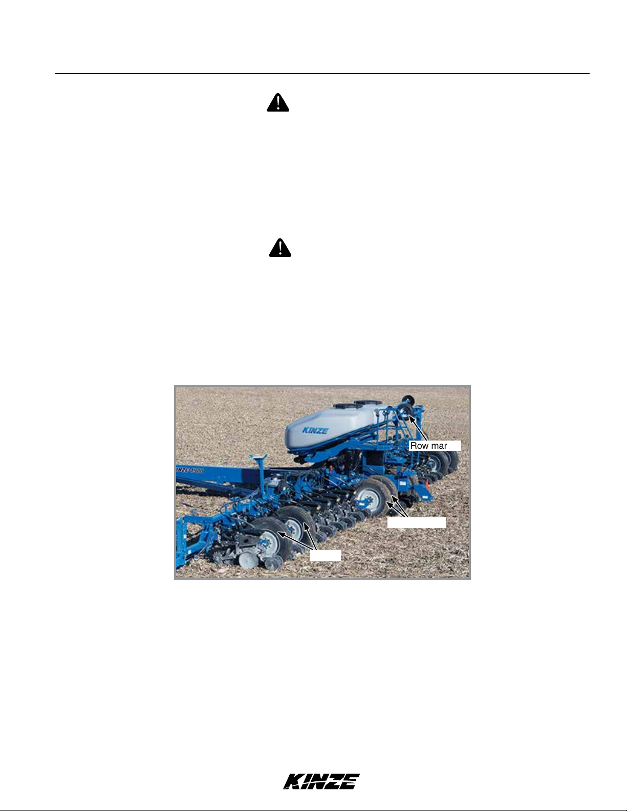
The Model 4900 Front Folding Planter is available in multiple sizes and row configurations with vacuum meter or
mechanical meters, conventional hoppers or bulk fill, liquid fertilizer, and various other options. Contact your Kinze Dealer
for additional details.
Model 4900 24 Row Bulk Fill Planter
Information used in these instructions was current at time of printing. However, due to Kinze’s ongoing product
improvement, production changes may cause your machine to appear slightly different in detail. Kinze Manufacturing,
Inc. reserves the right to change specifications or design without notice and without incurring obligation to install the
same on machines previously manufactured.
Right hand (R.H.) and left hand (L.H.), as used throughout this manual, are determined by facing direction machine
travels in use unless otherwise stated.
1-2 Rev. 5/14
TM

Specifications
Model 4900M0247-01
Specifications
Specification Conventional Hoppers Bulk Fill
Number of Rows 12R 30 16R 30 24R 30 12R 30 16R 30 24R 30
Row Spacing 30" 30" 30" 30" 30" 30"
Weight Empty (Vacuum Meter) 16,370 lb 20,810 lb 30,875* lb 17,070 lb 21,490 lb 31,525* lb
*add 165 lb for optional flip axle (24R only)
Transport Height
(with optional row marker package)
Planting Height 8'-8" 8'-8" 8'-8" 8'-9" 8'-11" 9'-3"
Planting Length 20'-3" 21'-8" 28'-8" 20'-3" 21'-8" 28'-8"
Transport Length 26'-11" 33'-5" 43'-8" 26'-11" 33'-5" 43'-8"
Planting Width 32' -0" 43'-9" 62'-4" 32' -0" 43'-9" 62'-4"
Transport Width (14'-0" with granular
chemical option)
Seed Capacity 1.90 bu. / 3.0 bu. 90 bu. 120 bu. 120 bu.
Bulk Fill Dimensions
(planting position height)
Transport Tire Size (4)
Transport Tire Pressure
11'-7" 11'-7" 11'-7" 11'-7" 11'-9" 12'-0"
11'-4" 12'-0" 12'-0" 11'-4" 12'-0" 12'-0"
9' 4"
255-70R
22.5
41" x 11" R
22.5
41" x 11" R
22.5
255-70R
22.5
41" x 11" R
22.5
41" x 11" R
22.5
100 psi 75 psi 75 psi 100 psi 75 psi 75 psi
Wing Tires
Field Tire Pressure
Piston Pump Drive Tires (Optional)
Field Lift
Row Markers
7.5" x 20"
(2)
7.5" x 20"
(4)
41" x 11" R
22.5 (4)
7.5" x 20"
(2)
7.5" x 20"
(4)
41" x 11" R
22.5 (4)
40 psi 40 psi 60 psi 40 psi 40 psi 60 psi
(2) 7.60" x 15"
12R - Four Master/Two Slave Hydraulics
16R/24R - Four Master/Four Slave Hydraulics
Independently controlled, three stage fold, disk blade depth bands.
Rev. 5/14 1-3
TM

Specifications
Tractor Hydraulic Requirements
#1 SCV: Planter Lift
#2 SCV: Markers/Fold
#3 SCV: Weight Distribution/ASD/Fertilizer
#4 SCV: Power Pack/Hydraulic Drive
#5 & #6 SCV: Vacuum (PTO)
Configuration Requirements*
24R without PTO pump option 54 gpm 6 SCV
24R with PTO pump option 37 gpm 4 SCV
16R without PTO pump option 47 gpm 6 SCV
16R with PTO pump option 37 gpm 4 SCV
12R without PTO pump option 46 gpm 6 SCV
M0247-01Model 4900
12R with PTO pump option 37 gpm 4 SCV
*Add 4 gpm for fertlizer pump option
NOTE: Tractor-mounted PTO hydraulic pump supplies oil flow for Vacuum Meter hydraulic circuit.
NOTE: Power pack SCV should be set to maximum flow at all times.
NOTE: Tractor RPMs not recommended below 1750 RPMs.
1-4 Rev. 5/14
TM

General Safety Rules
Model 4900M0247-01
1. Read and understand instructions provided in this
manual and warning labels. Review these instructions
frequently!
2. This machine is designed and built with your safety
in mind. Do not make any alterations or changes to this
machine. Any alteration to design or construction may
create safety hazards.
3. A large portion of farm accidents happen from
fatigue or carelessness. Safe and careful operation of
tractor and planter will help prevent accidents.
4.
Never allow planter to be operated by anyone
unfamiliar with operation of all functions of the unit.
Operators must read and thoroughly understand all
instructions given in this manual before operating or
working on equipment.
5. Be aware of bystanders, particularly children!
Always look around to make sure it is safe to start tow
vehicle engine or move planter. This is particularly
important with higher noise levels and quiet cabs, as
you may not hear people shouting.
6. Make sure planter weight does not exceed towing
capacity of tractor, or bridge and road limits. This is
critical to maintain safe control and prevent death or
injury, or property and equipment damage.
15. Use of aftermarket hydraulic, electric, or PTO
drives may create serious safety hazards to you and
people nearby. If you install such drives, follow all
appropriate safety standards and practices to protect
you and others near this planter from injury.
16. Follow all federal, state/provincial and local
regulations when towing farm equipment on a public
highway. Use safety chain (not an elastic or nylon/
plastic tow strap) to retain connection between towing
and towed machines in the event of primary attaching
system separation.
17. Make sure all safety/warning lights, SMV sign, and
reflective decals are in place and working properly
before transporting the machine on public roads.
18. Limit towing speed to 15 MPH. Tow only with farm
tractor of a minimum 90 HP. Allow for unit length when
making turns.
19. Reduce speed prior to turns to avoid the risk of
overturning. Always drive at a safe speed relative to
local conditions and ensure your speed is slow enough
for a safe emergency stop.
20. Chemical application is often an integral part of
planting. Follow label instructions for proper chemical
mixing, handling and container disposal methods.
7. Never ride or allow others to ride on planter.
8. Store planter in an area away from human activity.
DO NOT permit children to play on or around the
stored unit.
9. Keep hands, feet, and clothing away from moving
parts. Do not wear loose-fitting clothing which may
catch in moving parts.
10. Always wear protective clothing, shoes, gloves, and
hearing and eye protection applicable for the situation.
11. Do not allow anyone to stand between tongue or
hitch and towing vehicle when backing up to planter.
13. Prevent electrocution, other injuries, or property
and equipment damage. Watch for obstructions such
as wires, tree limbs, etc. when operating machine. Be
aware of clearances during turns and when folding/
unfolding planter.
14. Reinstall all guards removed for maintenance
activities. Never leave guards off during operation.
21. Be familiar with safety procedures for immediate
first aid should you accidentally contact chemical
substances.
22. Use the proper protective clothing and safety
equipment when handling chemicals.
23. Chemicals are supplied with Material Safety Data
Sheets (MSDS) that provide full information about the
chemical, its effects on exposure, and first aid needs
in the event of an emergency. Keep your MSDS file
up-to-date and available for first responders in case of
emergency.
24. When servicing ground engaging components such
as opening disks and firming points, use special care
to avoid points and edges worn sharp during use.
25. Use professional help if you are unfamiliar with
working on hydraulic systems. Pressurized hydraulic
fluid can penetrate body tissue and result in death,
serious infection, or other injuries.
Rev. 5/14 1-5
TM

Safety Precautions
M0247-01Model 4900
Following are some common hazard warnings associated with this equipment. Pay close attention to all safety,
operating, and maintenance information in this manual and decals applied to your equipment.
DANGER!
Contacting or coming close to power lines or other high energy
sources will cause death or serious injury. Keep away from power
lines or high energy sources at all times.
WARNING
Improperly operating or working on this equipment could result in
death or serious injury. Read and follow all instructions in Operator
Manual before operating or working on this equipment.
WARNING
Falling equipment can cause death or serious injury. Install all lockup
devices or lower planter to ground before working on equipment.
WARNING
Explosive separation of rim and tire parts can cause death or serious
injury. Overinflation. rim and tire servicing, improper use of rims and tires,
or worn or improperly maintained tires could result in a tire explosion.
SAFETY SIGNS AND DECALS
WARNING
All safety/warning lights, reflective decals, and SMV sign must be
in place and visible before transporting machine on public roads or
death, serious injury, and damage to property and equipment may
result. Check federal, state/provincial, and local regulations before
transporting equipment on public roads.
Safety signs and decals are placed on the machine to warn of hazards and provide important operating and maintenance
instructions. Information on these signs are for your personal safety and the safety of those around you. FOLLOW ALL
SAFETY INSTRUCTIONS!
• Keepsignscleansotheycanbeeasilyseen.Washwithsoapandwaterorcleaningsolutionasrequired.
• Replacesafetysignsifdamaged,paintedover,ormissing.
• CheckreectivedecalsandSMVsignperiodically.Replaceiftheyshowanylossofofreectiveproperties.
• Cleanmachinesurfacethoroughlywithsoapandwaterorcleaningsolutiontoremovealldirtandgrease
when replacing decals.
NOTE: Safety sign and decal locations are shown in the Parts Manual for this machine.
NOTE: Style and locations of SMV sign, reflective decals, and safety/warning lights conform to ANSI/ASABE
S279.14 JUL 2008 and ANSI/ASABE S276.6 JAN 2005.
1-6 Rev. 5/14
TM
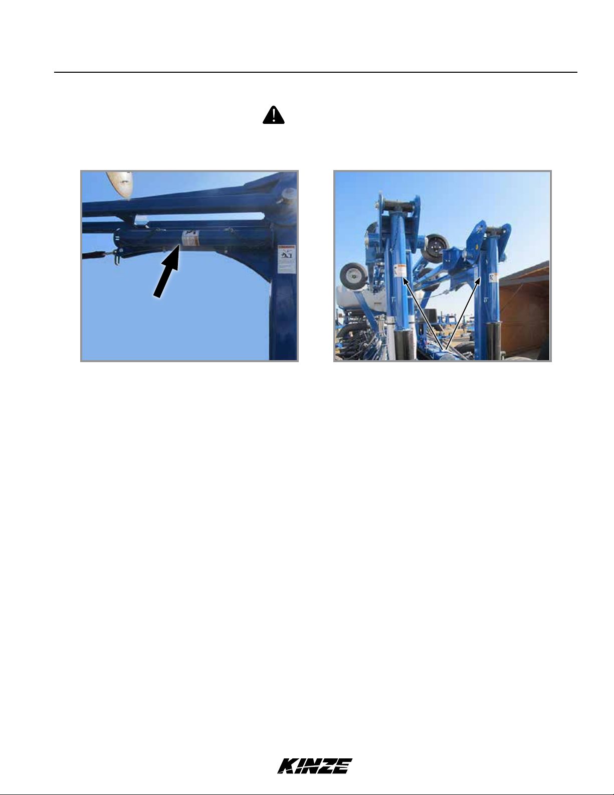
ROW MARKER SAFETY LOCKUP
Row marker can lower at any time and could cause death or serious
injury. Stay away from row markers! Install safety lockup device when
not in use.
Machine Operation
Model 4900M0247-01
WARNING
Row Marker Safety Lockup Stored
Row Marker Safety Lockup Installed
Always install row marker lockups when working on, storing, or transporting planter. Hold in place with two clevis pins.
Rev. 5/14 2-1
TM
Planter hitch may raise uncontrollably during folding/unfolding and
can cause death, serious injury, or damage property and equipment.
DO NOT fold or unfold planter without planter attached to a tractor.
DO NOT unhitch planter from tractor unless fully folded for transport
or fully unfolded with planting units lowered to ground.
Uncontrolled movement of equipment can cause loss of control
and could result in death, serious injury, or damage to property and
equipment. Install all safety pins before transporting equipment.
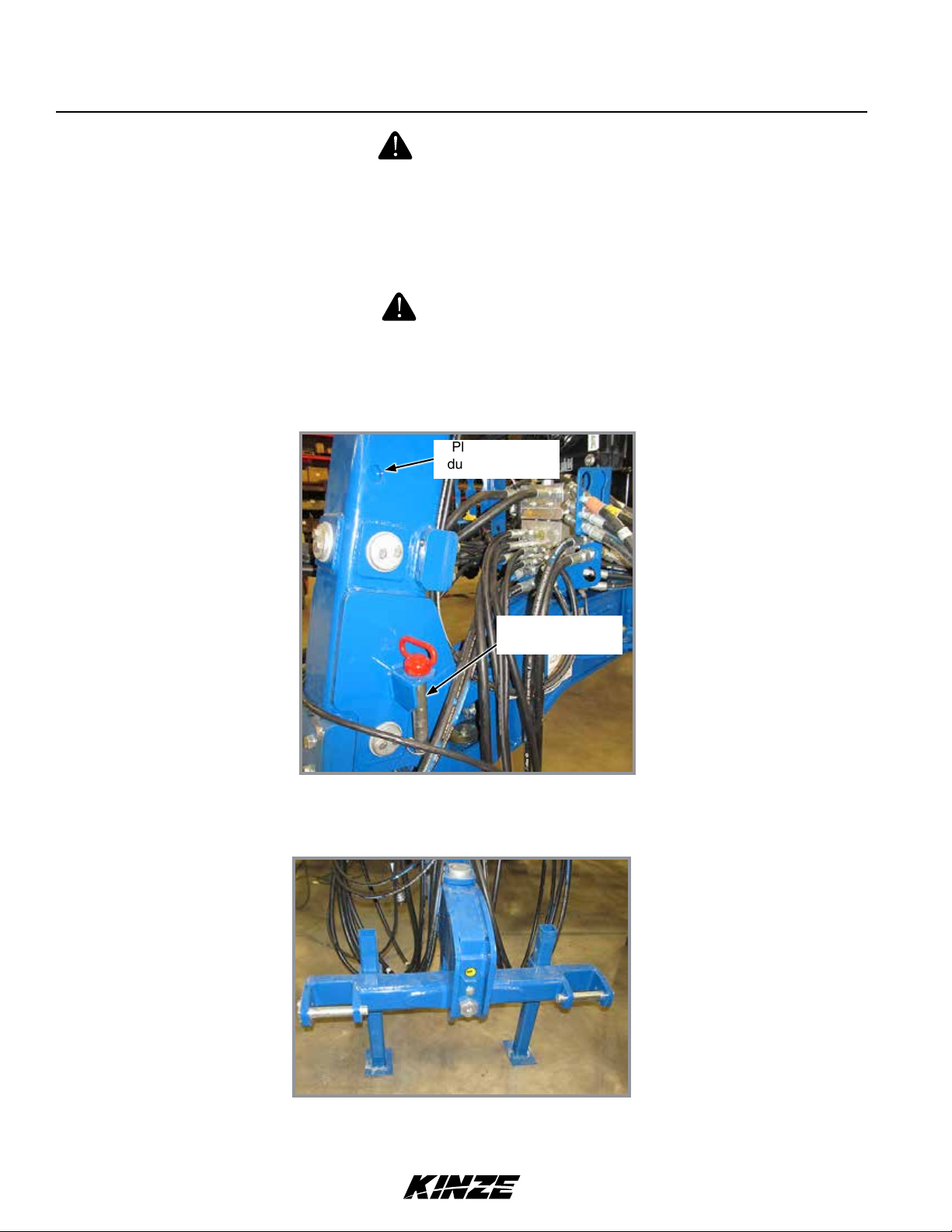
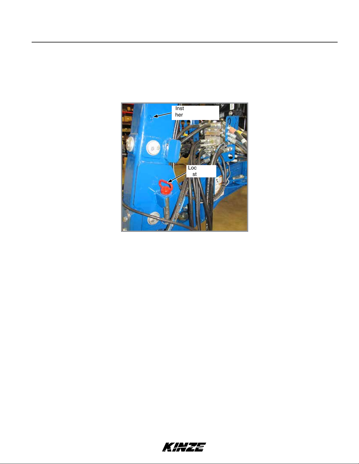
DRAWBAR HITCH LOCKUP (OPTION)
Machine Operation
M0247-01Model 4900
WARNING
WARNING
Place pin here
during transport
Place pin here
during operation
Place the drawbar hitch lockup pin in the hole shown above when machine is in operation.
2-POINT HITCH OPTION
Jacks in Maintenance Position
For transporting, store jacks on both sides of hitch. Secure in place with spring pin.
2-2 Rev. 5/14
TM
Machine Operation
Model 4900M0247-01
WARNING
Improperly operating or working on this equipment could result in
death or serious injury. Read and follow all instructions in Operator
Manual before operating or working on this equipment.
INITIAL PLANTER PREPARATION
Following information is general in nature to aid in preparation of tractor and planter for use, and to provide general
operating procedures. Operator experience, familiarity with the machine, and the following information should combine
for efficient planter operation and good working habits.
WARNING
Explosive separation of rim and tire can cause death or serious injury.
Overinflation, rim and tire servicing, improper use of rims and tires,
worn, or improperly maintained tires could result in a tire explosion.
WARNING
Wheel separation can cause loss of control resulting in death, serious injury, or damage to property and equipment. Check lug nuts
on transport wheels are tight before operating planter for first time
and periodically after.
Row marker
Transport
Wing
Tire locations (L.H. shown)
1. Torque transport wheel ¾"- 16 lug nuts to 200 ft-lb (244 N-m).
2. Inflate tires to the following specifications:
• Wing - 12R and 16R: 7.5" x 20" - 40 psi (275.7 kPa), 24R: 41" x 11" - 60 psi (413.6 kPa)
• Transport - 12R: 255-70R, 22.5 - 100 psi (689.4 kPa) 16R and 24R: 41" x 11" - 75 psi (517.1 kPa)
• Contact drive - 4.80" x 8" - 50 psi (344.7 kPa)
• Row marker - 16" x 6.5" x 8" - 14 psi (96.5 kPa)
• Liquid fertilizer piston pump (Not shown) - 4.10" x 6" - 50 psi (344.7 kPa)
3. Lubricate planter and row units per lubrication information in this manual.
4. Check all drive chains for proper tension, alignment, and lubrication.
Rev. 5/14 2-3
TM
Machine Operation
M0247-01Model 4900
TRACTOR REQUIREMENTS
WARNING
Loss of control of equipment during transport can result in death,
serious injury, or damage to property and equipment. Tractor gross
weight must be greater than planter gross weight with attachments
and options.
Consult your dealer for information on horsepower requirements and tractor compatibility. Requirements vary with planter
options, tillage, and terrain.
Three dual remote hydraulic outlets (SCV) are required on all sizes of conventional planters equipped with row markers.
Four dual remote hydraulic outlets (SCV) are required on all sizes of bulk fill planters equipped with row markers. A 12
volt DC electrical system is required on all sizes.
Six dual remote hydraulic outlets (SCV) are required on all sizes of planters equipped with vacuum meters but without
PTO pump.
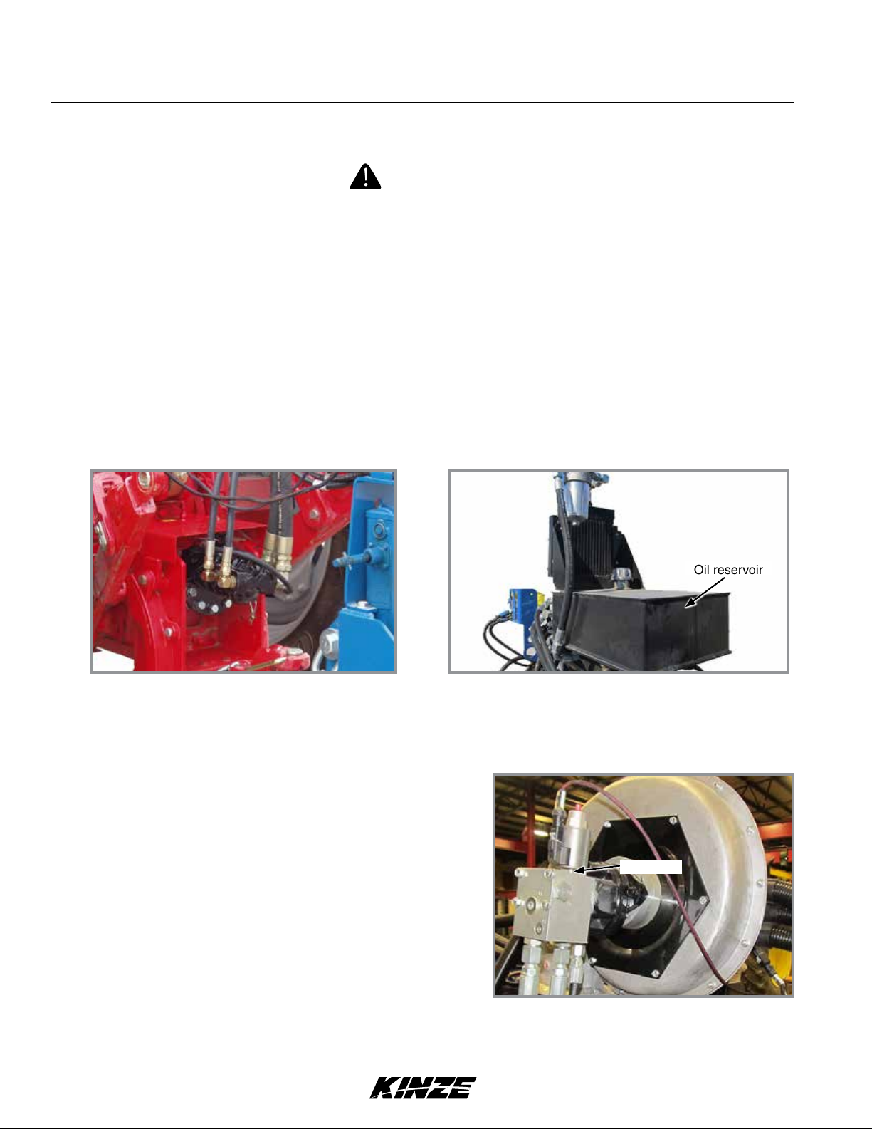
VACUUM METER TRACTOR MOUNTED PTO PUMP AND PLANTER MOUNTED HYDRAULICS
Oil reservoir
Two-section PTO Hydraulic Pump 8 gal (30.3 L) Reservoir
Vacuum meter equipped planters require a 1¾"-20 spline 1000 RPM PTO to operate PTO-driven two section hydraulic
pump capable of supplying 15 gpm (56.8 Lpm) to two hydraulic motors/vacuum fans.
NOTE: A tractor model-specific mount kit is required for the PTO-mounted pump.
Contact GnL Engineering (319-227-7222) or Rowe
Manufacturing (800-544-4123) for your tractor pump mount
requirements.
Vacuum Seed Metering System operates from an 8 gal
(30.3 L) capacity oil reservoir.
NOTE: Check that open center plug is removed from fan
block before operating.
Fan block
Vacuum Fan Block
Other dual fan system components include one oil cooler, one replaceable cartridge-type filter, and two pressure
compensating flow-control valves.
2-4 Rev. 5/14
TM
Machine Operation
TRACTOR PREPARATION AND HOOKUP
1. Back tractor to planter and connect with minimum
1¼" diameter hitch pin or 2 point hitch. Make sure
hitch pin is secured with a locking pin or cotter pin
if tractor is not equipped with a hitch pin locking
device or 2-point hitch.
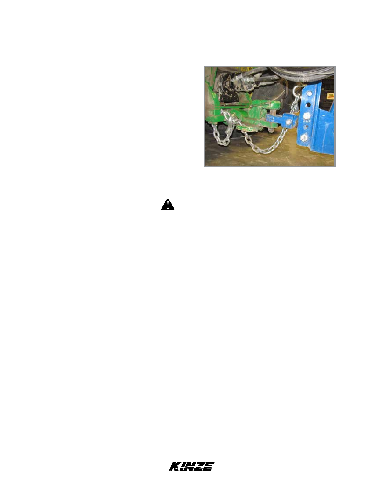
NOTE: DO NOT install safety chain using clevis
mounting hardware. Safety chain MUST be
installed separately.
2. For planters with drawbar hitch, safety chain must
be used to keep planter and tractor connected in
case of a hitch pin/drawbar failure. Attach safety
chain at an unused clevis mounting hole on the
planter hitch. Torque hardware to 840 ft-lb (1138.8
N-m).
Model 4900M0247-01
Tractor and Safety Chain Hookup
for Drawbar Hitch
WARNING
Pressurized hydraulic fluid can penetrate body tissue and result in
death, serious infection, or other injuries. Fluid injected under skin
must be IMMEDIATELY removed by a surgeon familiar with this
type of injury. Make sure connections are tight and hoses and
fittings are not damaged before applying system pressure. Leaks
can be invisible. Keep away from suspected leaks. Relieve pressure
before connecting or disconnecting tractor, searching for leaks, or
performing any system maintenance.
NOTICE
Wipe hose ends to remove any dirt before connecting couplers to
tractor ports or contamination may cause equipment failure.
NOTICE
Connect hydraulic motor case drain to a case drain return line with
zero PSI on tractor. Failure to connect to a return with zero PSI will
cause hydraulic motor shaft seal damage. DO NOT connect hydraulic
motor case drain to a SCV outlet or motor return circuit connection.
Contact tractor manufacturer for specific details on “zero pressure
return”.
NOTICE
Always connect hydraulic motor return hose to tractor motor return
port. Do not connect to tractor SCV unless through a motor spool
or hydraulic motor failure can occur. If a motor return port is not
available on the tractor, the SCV controlling the bulk fill system
MUST be in the float position before planter is moved in planting or
field raised position when bulk fill system is not in use.
5. Connect hydraulic hoses to tractor ports in a sequence familiar and comfortable to the operator. Refer to chart on
the following page.
Rev. 5/14 2-5
TM

Machine Operation
Color and Label Machine Function Hose Size Hose Function
Red AA Field Lift ½" Pressure/Return
Red BB ½" Pressure/Return
Blue AA Planter Fold & Row Marker " Pressure/Return
Blue BB " Pressure/Return
Black RR Power Pack
Black PP ½" Pressure
Orange CD
Yellow RR Bulk Fill System Pressure Fan
Yellow PP ½" Pressure
(Hydraulic Weight Transfer)
Orange CD
Green RR Vacuum Meter Fans /" Return
Green PP ½" Pressure
Orange CD " Case Drain
/
Return
" Case Drain
/" Return
" Case Drain
M0247-01Model 4900
NOTICE
Clean and grease PTO shaft coupling with high-pressure industrial
coupling grease (Chevron® coupling grease or equivalent) meeting
AGMA CG-1 and CG-2 Standards each time driveshaft is installed or
premature wear and equipment failure can occur.
NOTE: A tractor model-specific PTO mount kit is required and available from GnL Engineering (319-227-7222
or gnlengineering.net) and Rowe Manufacturing (800-544-4123 or rowemfg.com).
6. (If applicable) Install PTO pump onto tractor PTO shaft. Make sure shaft rotation matches direction indicated on
pump housing.
7. If equipped with ISOBUS system, attach ISO connector.
8. For planters not equipped with ISOBUS, connect ASABE Standards 7 terminal connector for safety/warning
lights on planter to ASABE Standards receptacle on tractor. If your tractor is not equipped with an ASABE
Standards receptacle, check with your tractor manufacturer for availability. Check warning lights on planter work in
conjunction with warning lights on tractor.
9. Completely raise parking stands to prevent damage to stands and equipment when moving planter.
10. (If applicable) Connect compressor harness.
2-6 Rev. 5/14
TM

TRANSPORTING PLANTER
Uncontrolled movement of equipment can cause loss of control
and could result in death, serious injury, or damage to property and
equipment. Install all safety pins before transporting equipment.
Uncontrolled machine movement can crush or cause loss of control
resulting in death, serious injury, or damage to property and equipment.
Install all safety lockup devices before working under or transporting
this equipment.
Transporting planter with hoppers over half full or unevenly loaded
can cause loss of control and could result in death, serious injury,
or damage to property and equipment. Properly load planter when
transporting. Be aware of extra transport weight, and road conditions
and limits.
Machine Operation
Model 4900M0247-01
WARNING
WARNING
WARNING
WARNING
To avoid unintended movement of axle during transport, return all
SCV controls to the neutral position before transporting machine.
DO NOT operate any hydraulic function while transporting machine.
Doing so could result in death, serious injury, or damage to property
and equipment.
Make sure safety/warning lights, reflective decals, and SMV sign are in place and visible before transporting machine
on public roads. It is your responsibility to check and comply with all federal, state/provincial, and local regulations.
Be aware of road and bridge weight limits. Allow for additional weight of added options and any additional material or
substances that have been added to the machine.
Rev. 5/14 2-7
TM
LEVEL PLANTER
Machine Operation
M0247-01Model 4900
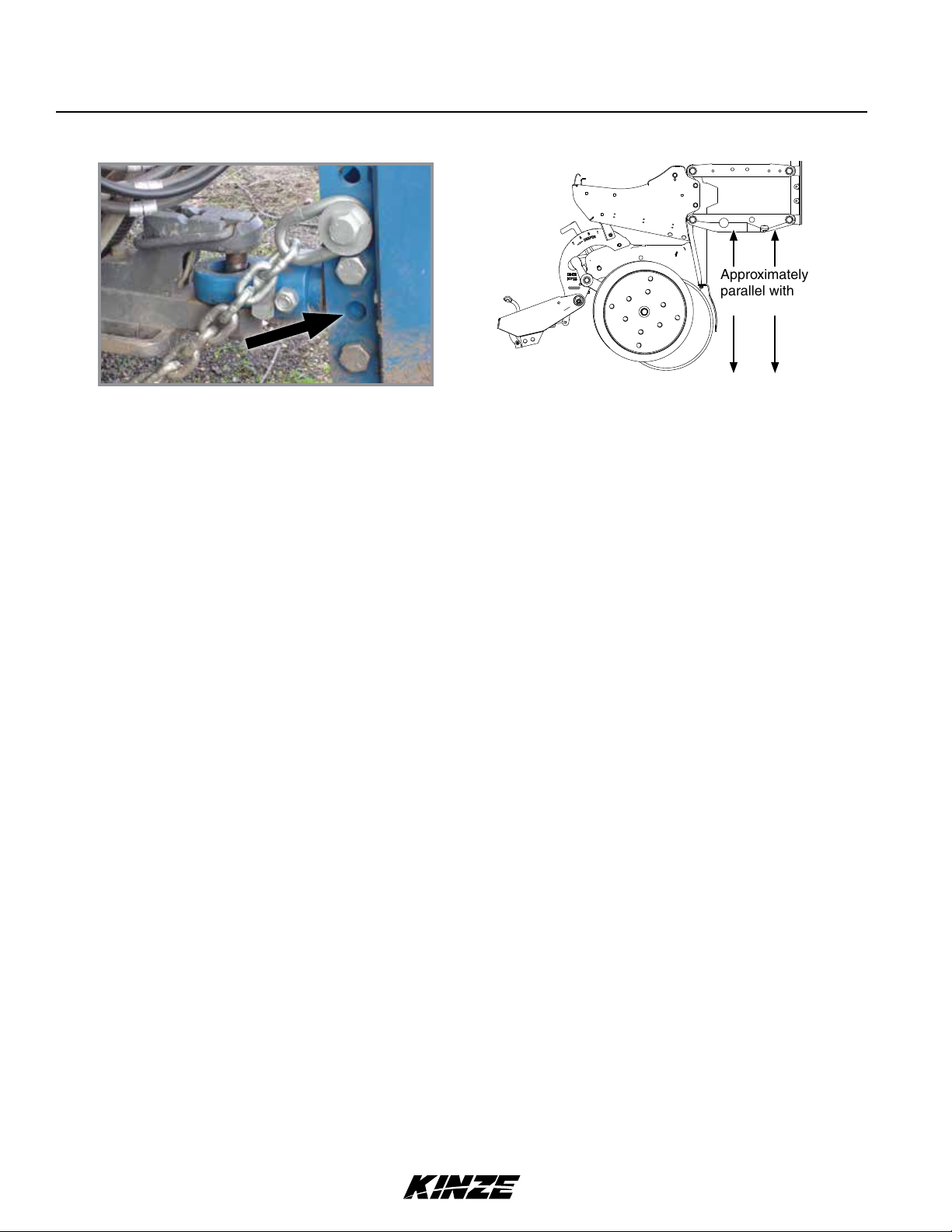
Approximately
parallel with
planting surface
Clevis Adjustment Holes
Level Row Units
Toolbar should operate at 23"-25" height from planting surface. Tire pressures must be maintained at pressures
specified for planter to operate level laterally. Check toolbar and row unit parallel arms are level front to back with
planter lowered to proper operating height.
Five holes in the hitch bracket allow clevis to be raised or lowered. Clevis may be turned over for a finer adjustment
between mounting holes. Torque hardware to 840 ft-lb (1138.8 N-m).
Field and actual planting conditions determine which wheel settings to use to ensure row unit parallel arms are
approximately parallel with planting surface. If planting in extremely soft soil conditions it may be necessary to move
ground drive tires to lower sets of mounting holes. To allow adequate drive force after lowering the ground drive tires,
it may be necessary to lower contact drive arms to lower set of holes in wheel module and relocate down pressure
springs to lower mounting rod on wheel module.
If planter center is higher or lower than wings after rephasing, contact your Kinze Dealer for valve adjustment or
maintenance.
2-8 Rev. 5/14
TM

Machine Operation
Model 4900M0247-01
JUMP START SENSOR
The jump start sensor is intended to reduce the seed
gap when starting from a stop with the planter in the
ground. For the jump start sensor to work as intended,
the planter speed sensor needs to be set within /” of
the pick-up disc. The planter speed sensor also needs
to be calibrated properly. Refer to the ISOBUS manual
for calibration instructions.
If the planter speed sensor is set-up properly, the startup gap should be no more than 4 feet.
If no gap is desired, there are two options for
eliminating the gap completely:
1. Use the jump start button available on the
ISOBUS display. Pressing this button will start
turning the drives. Once a speed source is
acquired, it will take over control. Refer to the
ISOBUS manual for further instructions on the
jump start button.
2. Pick the planter up, back up 10 - 12 feet,
set the planter down and resume planting. The
section control will turn the drives on at the
correct time.
Jump start sensor
Pick-up disc
Jump Start Sensor and Pick-up Disc
FIELD OPERATION
Planters are designed to operate within a speed range of 2 - 8 mph (3 - 13 kph). Higher ground speeds can cause
more variation in seed spacing. Speeds above 6.5 mph (10.5 kph) are typically not recommended.
NOTICE: Always raise planter out of ground when making sharp turns or backing up.
Normal field planting operation requires use of tractor's hydraulic control to raise and lower planter frame when
making field turnarounds.
NOTICE: Operate row markers in float position to prevent damage to row markers.
Operate row markers with ISOBUS control or tractor's hydraulic control. After markers are lowered to ground, move
hydraulic control to operate markers in float position. Marker speed is controlled with flow control valves located in
planter hitch valve block. One valve controls raise speed and other valve controls lower speed of both markers. See
“Row Marker Speed Adjustment” on page 2-35 and “Row Marker Cable Adjustment” on page 2-36.
Rev. 5/14 2-9
TM

Machine Operation
TRANSPORT TO FIELD SEQUENCE USING ISOBUS
Position planter in a relatively flat open area without furrows, etc.
SUMMARIZED TRANSPORT TO FIELD SEQUENCE
USING ISOBUS VIRTUAL TERMINAL
NOTICE
Folding planter without using tractor to assist may cause equipment damage
especially in soft conditions or when loaded with seed or fertilizer. Use tractor
to reduce stress on frame, drive, and transport components.
1. Lower transport axle to field turnaround position.
2. Lower wing wheels into field turnaround position.
3. Lower drawbar or 2-point hitch to unhook wings.
4. Fold wings out, away from tractor. Planter is completely unfolded
when stub wings are latched into the H-frame.
5. Lower drawbar or 2-point hitch to level machine during planting.
6. Lower planter and hold hydraulic lever for an additional 10-15
seconds to rephase cylinders.
M0247-01Model 4900
NOTE: Read following information for detailed instructions.
2-10 Rev. 5/14
TM

Machine Operation
DO NOT fold or unfold planter without planter attached to a tractor.
DO NOT unhitch planter from tractor unless fully folded for transport
or fully unfolded with planting units lowered to ground.
1. Remove and store locking pin on drawbar hitch.
Model 4900M0247-01
NOTICE
Install locking pin
here for transport
Locking pin
storage
Locking Pin for Drawbar Hitch
Rev. 5/14 2-11
TM
Machine Operation
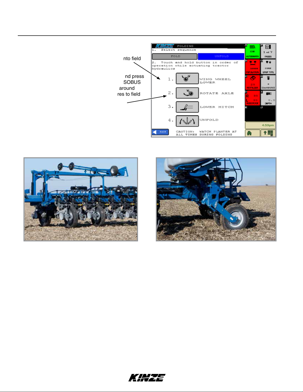
2. Operate the proper hydraulic tractor control and
press and hold the WING WHEEL LOWER button on
your ISOBUS monitor to lower wing wheels into field
turnaround position.
3. Operate the proper hydraulic tractor control and press
and hold the ROTATE AXLE button on your ISOBUS
monitor to lower transport axle to field turnaround
position. If equipped with flip axle, move tires to field
turnaround position as shown below.
M0247-01Model 4900
ISOBUS Monitor Unfold Screen
Wing Wheels in Field Turnaround Position
2-12 Rev. 5/14
Flip Axle in Field Turnaround Position
TM
Machine Operation
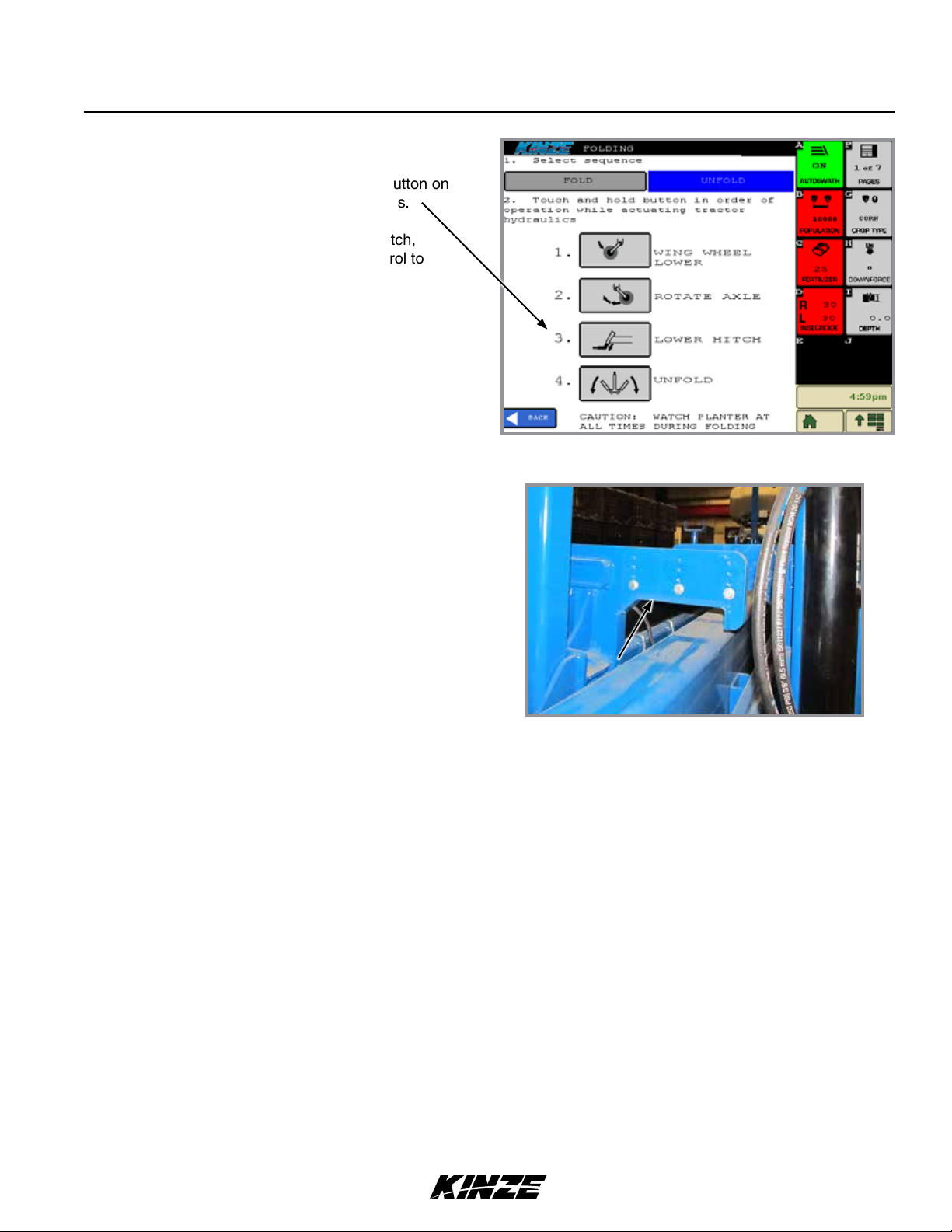
4. For planters equipped with drawbar hitch,
operate proper hydraulic tractor control and
press and hold the LOWER HITCH button on
your ISOBUS monitor to unhook wings.
For planters equipped with 2-point hitch,
operate proper hydraulic tractor control to
lower drawbar to unhook wings.
Model 4900M0247-01
ISOBUS Monitor Unfold Screen
Hitch Release from Wing Hook
Rev. 5/14 2-13
TM
Machine Operation
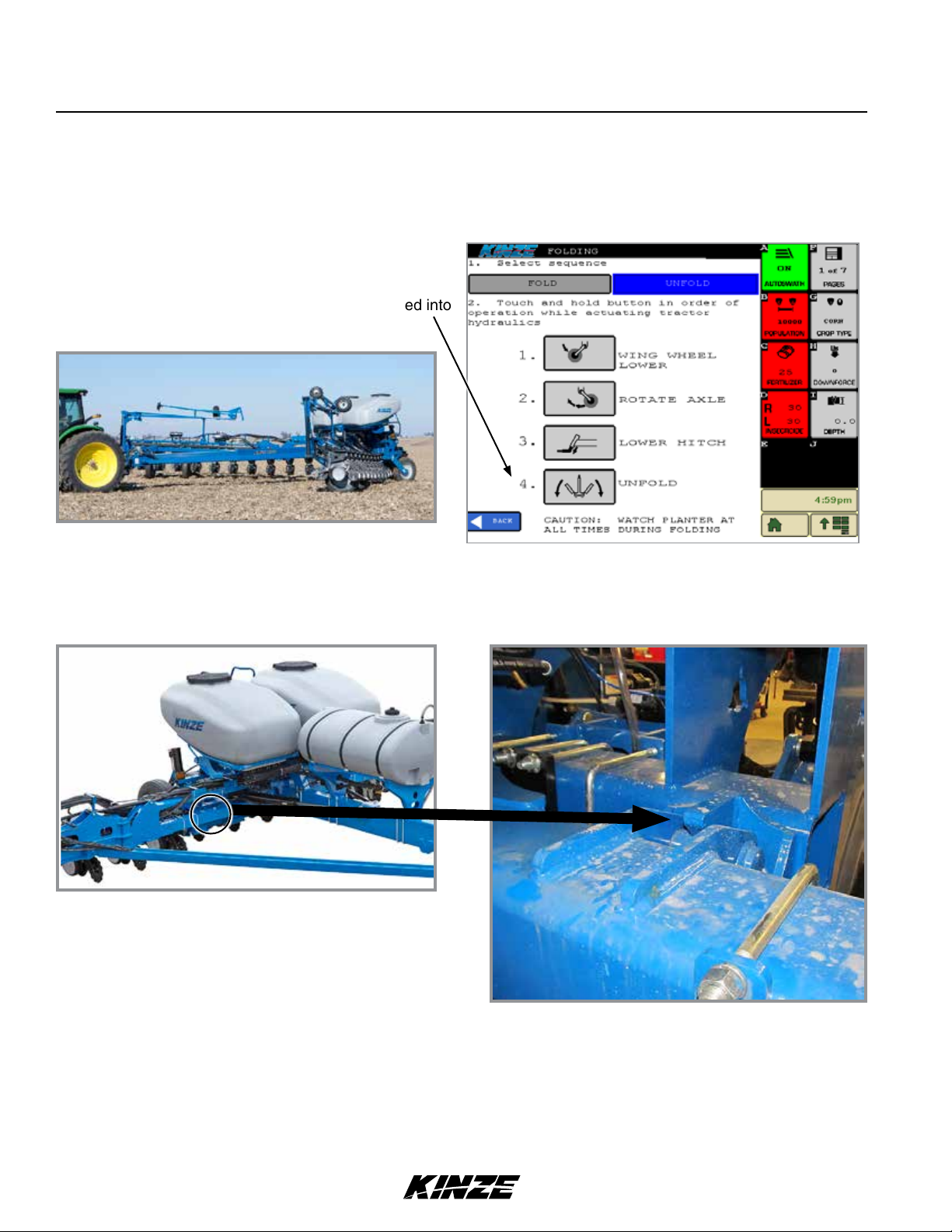
NOTICE
Unfolding planter without using tractor to assist may cause equipment
damage especially in soft conditions or when loaded with seed or
fertilizer. Use tractor to reduce stress on frame, drive, and transport
components.
5. Operate the proper hydraulic tractor control and press
and hold the UNFOLD button on your ISOBUS monitor
to move wings out, away from tractor. Planter is
completely unfolded when stub wings are latched into
the H-frame as shown in bottom photos.
M0247-01Model 4900
Planter Unfolding
Stub Wing Latched into Frame
ISOBUS Monitor Unfold Screen
2-14 Rev. 5/14
TM
Machine Operation
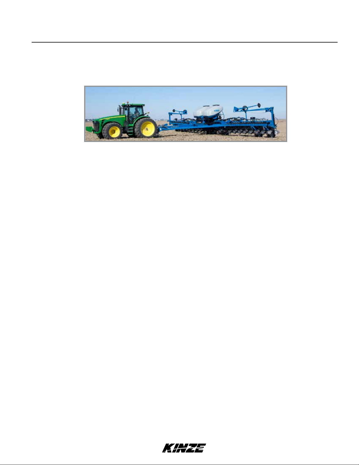
6. Lower drawbar or 2-point hitch to level machine during planting.
7. Lower planter and hold hydraulic lever for an additional 10-15 seconds to rephase cylinders.
Model 4900M0247-01
Rev. 5/14 2-15
TM

Machine Operation
TRANSPORT TO FIELD SEQUENCE USING CONTROL BOX
Position planter in a relatively flat open area without furrows, etc.
SUMMARIZED TRANSPORT TO FIELD SEQUENCE
USING CONTROL BOX
NOTICE
Folding planter without using tractor to assist may cause equipment damage
especially in soft conditions or when loaded with seed or fertilizer. Use tractor
to reduce stress on frame, drive, and transport components.
The control box and VT (virtual terminal) should not be used at the same time.
Make sure the markers are disabled on the VT when the control box is being
used to fold/unfold the planter.
Unfolding the planter without putting the tractor in neutral and allowing the
tractor to move may cause damage to the equipment.
M0247-01Model 4900
1. Place function switch on control box in fold position.
2. Put tractor in neutral. Lower wing wheels.
3. Lower planter to field turnaround position.
4. Lower hitch to release wing hooks. Unfold the planter.
5. Lower the planter to the ground and hold for 30 seconds to
rephase the lift cylinders.
6. Remove the row marker lockups and place in storage holder.
NOTE: Read following information for detailed instructions.
2-16 Rev. 5/14
TM
Machine Operation
DO NOT fold or unfold planter without planter attached to a tractor.
DO NOT unhitch planter from tractor unless fully folded for transport
or fully unfolded with planting units lowered to ground.
1. Remove and store locking pin on drawbar hitch.
Model 4900M0247-01
NOTICE
Install locking pin
here for transport
Locking pin
storage
Locking Pin for Drawbar Hitch
Rev. 5/14 2-17
TM
Machine Operation
M0247-01Model 4900
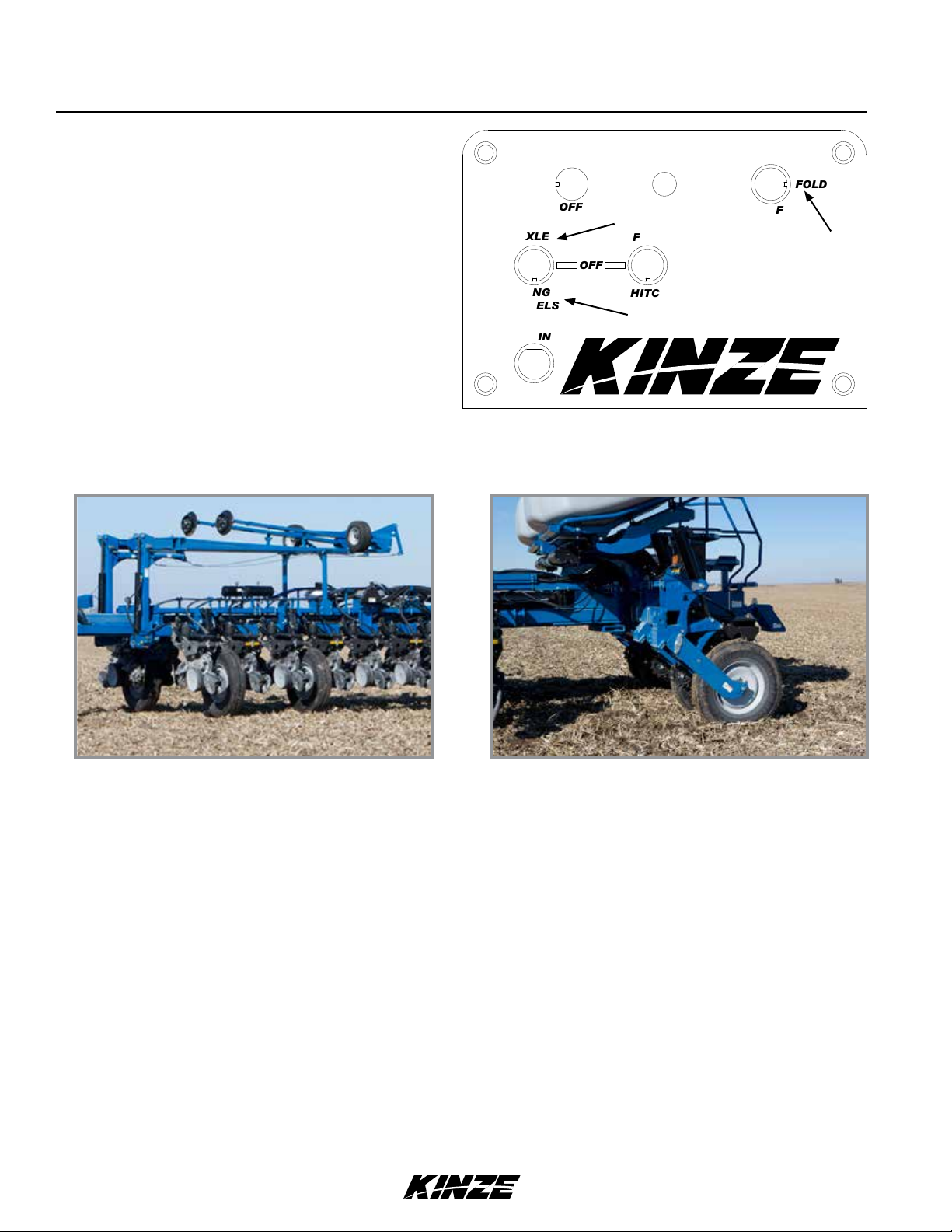
2. Place FUNCTION switch on control box in fold
position.
3. Operate the proper hydraulic tractor control and press
and hold the WING WHEEL switch down to lower wing
wheels into field turnaround position.
4. Operate the proper hydraulic tractor control and press
and hold the AXLE switch up to lower transport axle
to field turnaround position. If equipped with flip axle,
move tires to field turnaround position as shown below.
MARKERS
LEFT
AXLE
WING
WHEELS
MAIN
15 AMP
OFF
RIGHT
OFF
FOLD
HITCH
Control Box
PLANT
FUNCTION
FOLD
OFF
TM
Wing Wheels in Field Turnaround Position
2-18 Rev. 5/14
Flip Axle in Field Turnaround Position
TM
 Loading...