

Kinze 3660 User Manual
MODEL 3660
TWIN-LINE PLANTER
OPERATOR MANUAL
M0217-01 Rev. 7/14
This manual is applicable to: Model 3660 Twin-Line Planter
2009 to 2014 Production
Record the model number and serial number of your planter along with date purchased:
Model Number ____________ _____________________
Serial Number ___________________________________
Date Purchased __________________________________
Monitor Serial Number _______________________________________________
Measured Pulses Per Mile/Km (Radar Distance Sensor) ____________________
Measured Pulses Per Mile/ Km (Magnetic Distance Sensor) _________________
3660
SERIAL NUMBER
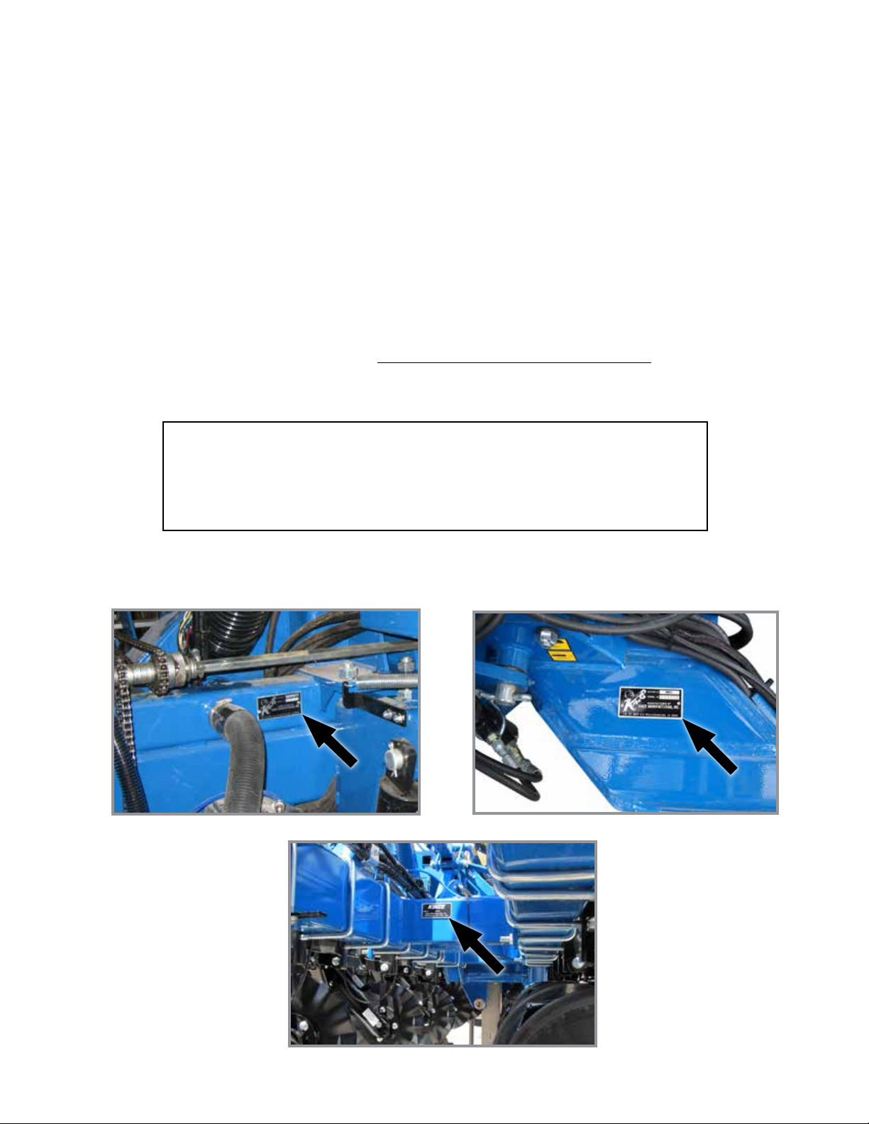
The serial number plate is located on the planter frame as shown below. The serial number provides important information
about your planter and is needed to obtain correct replacement parts. Always provide model number and serial number
to your Kinze Dealer when ordering parts or when contacting Kinze Manufacturing, Inc.
2009 production and earlier
2013 production and on
Kinze®, the Kinze® logo, Twin-Line®, Interplant®, and EdgeVac® are registered trademarks of Kinze Manufacturing, Inc.
2010 to 2012 production

This page intentionally left blank.

Predelivery/Delivery Checklist
Model 3660M0217-01
TO THE DEALER
Predelivery service includes assembly, lubrication, adjustment and test. This service helps ensure planter is delivered
to retail customer/end user ready for field use.
PREDELIVERY CHECKLIST
Use the following checklist after planter is completely assembled. Check off each item as it is found satisfactory or after
proper adjustment is made.
Center pivot base mounting and transport wheel spindle hex head cap screws torqued to 450 ft-lb (610.1 n-m).
Row units properly spaced and optional attachments correctly assembled.
Row marker assemblies installed and adjusted at each end of the planter.
EdgeVac and ASD components properly installed (as applicable).
All grease fittings in place and lubricated.
All working parts move freely, bolts are tight, and cotter pins are spread.
Check all drive chains for proper tension and alignment.
Check for oil leaks and proper hydraulic operation.
Hydraulic hoses correctly routed to prevent damage.
Inflate tires to specified air pressure and torque wheel lug bolts and lug nuts as specified in the manual.
All safety decals correctly located and legible. Replace if damaged.
All reflective decals and SMV sign correctly located and visible when the planter is in transport position.
Safety/warning lights correctly installed and working properly.
Paint all parts scratched during shipment or assembly.
All safety lockup devices on the planter and correctly located.
Auxiliary safety chain properly installed and hardware torqued to specification.
Vacuum fan PTO-driven pump correctly attached to tractor. Oil reservoir filled to capacity and system inspected for
leaks (If applicable).
Control box properly installed in tractor. All cables correctly routed and secure.
Planter has been thoroughly checked and to the best of my knowledge is ready for delivery to the customer.
(Signature Of Set-Up Person/Dealer Name/Date)
OWNER REGISTER
Name Delivery Date
Street Address Model No. 3660 Serial No.
City, State/Province Dealer Name
ZIP/Postal Code Dealer No.
Rev. 7/11 1
TM

Predelivery/Delivery Checklist
M0217-01Model 3660
DELIVERY CHECKLIST
Use the following checklist at time planter is delivered as a reminder of very important information which should be
conveyed to retail customer/end user. Check off each item as it is fully explained.
Check proper operation of vacuum fan, ASD fan, and PTO-driven pump (If applicable) with tractor used with planter.
Life expectancy of this or any other machine is dependent on regular lubrication as directed in the Operator Manual.
All applicable safety precautions.
Along with retail customer/end user, check reflective decals and SMV sign are clearly visible with planter in transport
position and attached to tractor. Check safety/warning lights are in working condition. Tell retail customer/end user
to check federal, state/provincial, and local regulations before towing or transporting on a road or highway.
Give Operator Manual, Parts Manual, and all Instruction Sheets to retail customer/end user and explain all operating
adjustments.
Read warranty to retail customer/end user.
Complete Warranty and Delivery Report form.
To the best of my knowledge this machine has been delivered ready for field use and customer has been fully
informed as to proper care and operation.
(Signature Of Delivery Person/Dealer Name/Date)
AFTER DELIVERY CHECKLIST
The following is a list of items we suggest to check during the first season of use of the equipment.
Check planter performance with retail customer/end user.
Check performance of EdgeVac or mechanical seed metering system with retail customer/end user.
Review importance of proper maintenance and adherence to all safety precautions with retail customer/end user.
Check for parts that may need to be adjusted or replaced.
Check all safety decals, reflective decals, and SMV sign are correctly located as shown in the Parts Manual and that
decals are legible. Replace if damaged or missing.
Check safety/warning lights are working properly.
(Signature Of Follow-Up Person/Dealer Name/Date)
All registrations must be submitted online at “business.kinze.com” within 5 business days of delivery.
Retain a copy of this form for auditing purposes.
Tear Along Perforation
Rev. 6/14
2
TM

Table of Contents
Model 3660M0217-01
MACHINE OPERATION
Planter Lift Safety Lockup .........................2-1
Row Marker Safety Lockup ........................2-1
Tongue Safety Pin ...............................2-2
Transport Latch Locking Pin .......................2-2
Initial Preparation ................................2-3
Tractor Mounted PTO Pump And Oil Cooler Option .....2-4
Planter Mounted PTO Pump And Oil Cooler Option .....2-5
Tractor Requirements. . . . . . . . . . . . . . . . . . . . . . . . . . . . . 2-5
Tractor Preparation and Hookup ....................2-6
Level Planter ...................................2-8
Ridge Planting . . . . . . . . . . . . . . . . . . . . . . . . . . . . . . . . . . 2-9
Control Console Operation .......................2-10
Hydraulic Seed Rate Drive. . . . . . . . . . . . . . . . . . . . . . . . 2-11
Hall Effect Sensor (Hydraulic Drive Only) ............2-11
Hydraulic Weight Transfer Toolbar ..................2-11
Row Unit Air Clutches ...........................2-11
Ag Leader Electric Clutches ......................2-11
Transport to Field Sequence ......................2-12
Field Operation ................................2-14
Planting Speed ................................2-14
Field to Transport Sequence ......................2-15
EdgeVac System ...............................2-17
Digital Vacuum Readout. . . . . . . . . . . . . . . . . . . . . . . . . . 2-17
Vacuum Fan Motor Valve Block Assembly . . . . . . . . . . . . 2-17
Analog Vacuum or Pressure Gauge. . . . . . . . . . . . . . . . . 2-17
Air Seed Delivery (ASD) System ...................2-18
ASD Entrainer Access ...........................2-18
ASD Tanks - Clean Out ..........................2-19
ASD Scale Package Option .......................2-19
Kinze Cobalt System ............................2-21
Ag Leader Integra Display . . . . . . . . . . . . . . . . . . . . . . . .2-22
Planter Monitor Module (PMM) ....................2-22
Auxiliary Work Lights Package. . . . . . . . . . . . . . . . . . . . . 2-22
Kinze ISOBUS Option ...........................2-22
Row Marker Operation ...........................2-23
Row Marker Speed Adjustment . . . . . . . . . . . . . . . . . . . . 2-24
Even-Row Push Row Unit ........................2-24
Row Marker Adjustments. . . . . . . . . . . . . . . . . . . . . . . . . 2-25
Row Marker Even-Row Length Adjustment ...........2-26
Offset Hitch Adjustment . . . . . . . . . . . . . . . . . . . . . . . . . . 2-26
Point Row Clutches .............................2-27
Auxiliary Hydraulic Option ........................2-28
Rear Trailer Hitch ...............................2-29
Field Test .....................................2-30
Field Check Seed Population. . . . . . . . . . . . . . . . . . . . . . 2-30
Determining Pounds Per Acre (Brush-Type Meter) .....2-31
Determining Bushels Per Acre. . . . . . . . . . . . . . . . . . . . . 2-31
Field Check Granular Chemical Application ..........2-32
ROW UNIT OPERATION
Planting Depth . . . . . . . . . . . . . . . . . . . . . . . . . . . . . . . . . .3-1
“V” Closing Wheel Adjustment (Rubber or Cast Iron) ....3-1
Closing Wheel Shield (Rubber or Cast Iron
“V” Closing Wheels) ............................3-1
Drag Closing Attachment. . . . . . . . . . . . . . . . . . . . . . . . . . 3-2
Covering Discs/Single Press Wheel Adjustment ........3-2
Seed Hoppers ..................................3-3
Seed Meter Drive Release. . . . . . . . . . . . . . . . . . . . . . . . . 3-3
Row Unit Extension Brackets. . . . . . . . . . . . . . . . . . . . . . . 3-3
Row Unit Chain Routing. . . . . . . . . . . . . . . . . . . . . . . . . . . 3-4
Quick Adjustable Down Force Springs Option (Standard or
Heavy Duty). . . . . . . . . . . . . . . . . . . . . . . . . . . . . . . . . . 3-5
Interplant Push Row Unit Clutch Sprocket. . . . . . . . . . . . . 3-8
Interplant Push Row Unit Vacuum Hose Shutoff ........3-8
Interplant Push Row Unit Lockups. . . . . . . . . . . . . . . . . . . 3-9
General Planting RATE Information . . . . . . . . . . . . . . . . . 3-11
Brush-Type Seed Meter . . . . . . . . . . . . . . . . . . . . . . . . . . 3-12
Finger Pickup Seed Meter . . . . . . . . . . . . . . . . . . . . . . . .3-13
EdgeVac Seed Meters ...........................3-14
Seed Meter Cleanout. . . . . . . . . . . . . . . . . . . . . . . . . . . . 3-17
Additives .....................................3-18
Frame Mounted Coulter (Pull Row) .................3-19
Residue Wheels (Frame Mounted Coulter) ...........3-19
Row Unit Mounted Disc Furrower (Pull Row) .........3-20
Row Unit Mounted Bed Leveler (Pull Row) ...........3-20
Row Unit Mounted Residue Wheel .................3-21
Row Unit Mounted No Till Coulter ..................3-22
Coulter Mounted Residue Wheels . . . . . . . . . . . . . . . . . . 3-22
Granular Chemical Hopper and Drive ...............3-23
Spring Tooth Incorporator ........................3-23
Granular Chemical Banding Options . . . . . . . . . . . . . . . .3-24
Granular Chemical Bander Shield . . . . . . . . . . . . . . . . . .3-24
Interplant Push Row Unit Lockups . . . . . . . . . . . . . . . . . . 3-25
FERTILIZER
Double Disc Fertilizer Opener ......................4-1
Notched Single Disc Opener . . . . . . . . . . . . . . . . . . . . . . . 4-2
Residue Wheel Attachment for Notched
Single Disc Fertilizer Opener. . . . . . . . . . . . . . . . . . . . . 4-3
Depth/Gauge Wheel Attachment for Notched
Single Disc Fertilizer Opener. . . . . . . . . . . . . . . . . . . . . 4-3
HD Single Disc Fertilizer Opener ....................4-4
Liquid Fertilizer Attachment ........................4-6
Rev. 6/14 i
TM

Table of Contents
M0217-01Model 3660
LUBRICATION AND MAINTENANCE
Lubrication . . . . . . . . . . . . . . . . . . . . . . . . . . . . . . . . . . . . .5-1
Lubrication Symbols .............................5-1
Sealed Bearings ................................5-1
Bushings ......................................5-3
Center Post ....................................5-4
Liquid Fertilizer Piston Pump ......................5-4
Crankcase Oil Level. . . . . . . . . . . . . . . . . . . . . . . . . . . . . . 5-4
PTO Pump Shaft Coupling (Tractor Driven PTO Pump and
Oil Cooler Option) . . . . . . . . . . . . . . . . . . . . . . . . . . . . . 5-5
Grease Fittings .................................5-6
Mounting Bolts and Hardware .....................5-10
Tractor Driven PTO Pump and Oil Cooler Option ......5-15
Finger Pickup Seed Meter Inspection/Adjustment. . . . . . 5-16
Cleaning Finger Pickup Seed Meter For Storage ......5-17
Brush-Type Seed Meter Maintenance ...............5-18
Cleaning Brush-Type Seed Meter For Storage ........5-19
Vacuum Manifold Maintenance ....................5-19
EdgeVac Seed Meter Maintenance . . . . . . . . . . . . . . . . . 5-20
EdgeVac Seed Meter Cleanout ....................5-20
Drag Closing Attachment ........................5-21
Gauge Wheel Adjustment ........................5-21
Gauge Wheel Arm Bushing and/or Seal Replacement 5-22
Gauge Wheel Arm Pivot Spindle Replacement . . . . . . . . 5-22
15" Seed Opener Disc Blade/Bearing Assembly .......5-23
Seed Tube Guard/Inner Scraper ...................5-24
Frame Mounted Coulter .........................5-24
Residue Wheels (For Use With Frame Mounted Coulter) 5-24
Row Unit Mounted Disc Furrower ..................5-25
Row Unit Mounted Bed Leveler . . . . . . . . . . . . . . . . . . . . 5-25
Row Unit Mounted No Till Coulter ..................5-25
Coulter Mounted Residue Wheels . . . . . . . . . . . . . . . . . . 5-26
Row Unit Mounted Residue Wheel .................5-26
Granular Chemical Attachment ....................5-26
Spring Tooth Incorporator ........................5-26
Pressure Reducing Relief Valve. . . . . . . . . . . . . . . . . . . . 5-27
Row Marker Bearing Lubrication or Replacement . . . . . . 5-28
Wheel Bearing Repack or Replacement .............5-30
Fertilizer Check Valve Cleaning and Repair ...........5-37
Piston Pump Storage. . . . . . . . . . . . . . . . . . . . . . . . . . . . 5-37
ISOBUS Implement Cable . . . . . . . . . . . . . . . . . . . . . . . . 5-55
ISOBUS CAN Jumper Cable . . . . . . . . . . . . . . . . . . . . . .5-55
Product Control Module Cable. . . . . . . . . . . . . . . . . . . . . 5-56
Implement Switch Extension Cable . . . . . . . . . . . . . . . . .5-57
Section Adapter Cable - 12 Row ...................5-58
Section Adapter Cable - 16 Row ...................5-58
Clutch Cable - 12 Row ...........................5-59
Clutch Cable - 16 Row ...........................5-60
TROUBLESHOOTING
Air Clutch . . . . . . . . . . . . . . . . . . . . . . . . . . . . . . . . . . . . . .6-1
Air Seed Delivery (ASD) ..........................6-1
Closing Wheel ..................................6-1
Lift Circuit Troubleshooting. . . . . . . . . . . . . . . . . . . . . . . . . 6-2
Piston Pump ...................................6-3
PTO Pump Drive and Oil Cooler Option ..............6-3
Rotation Circuit .................................6-4
Row Marker Operation ............................6-4
Seed Meter (Brush-Type). . . . . . . . . . . . . . . . . . . . . . . . . . 6-5
Seed Meter (EdgeVac). . . . . . . . . . . . . . . . . . . . . . . . . . . .6-6
Seed Meter (Finger Pickup) .......................6-8
Solenoid Valve . . . . . . . . . . . . . . . . . . . . . . . . . . . . . . . . . . 6-9
Tongue Cylinder Circuit ...........................6-9
Wing Lock Cylinder Circuit. . . . . . . . . . . . . . . . . . . . . . . . 6-10
Rev. 7/14
ii
TM

To The Owner
Model 3660M0217-01
Kinze Manufacturing, Inc. thanks you for your patronage. We appreciate your confidence in Kinze farm machinery. Your
Kinze planter has been carefully designed to provide dependable operation in return for your investment.
This manual has been prepared to aid you in the operation and maintenance of the planter. It should be
considered a permanent part of the machine and remain with the machine when you sell it.
It is the responsibility of the user to read and understand the Operator Manual in regards to safety, operation,
lubrication and maintenance before operation of this equipment. It is the user’s responsibility to inspect and service
the machine routinely as directed in the Operator Manual. We have attempted to cover all areas of safety, operation,
lubrication and maintenance; however, there may be times when special care must be taken to fit your conditions.
Throughout this manual the symbol and the words DANGER, WARNING, and CAUTION are used to call
attention to safety information that if not followed, will or could result in death or injury. NOTICE and NOTE are used to
call your attention to important information. The definition of each of these terms follows:
DANGER Indicates a hazardous situation which, if not avoided, will result in death or serious
injury.
WARNING Indicates a hazardous situation which, if not avoided, could result in death or serious
injury.
CAUTION, used with the safety alert symbol, indicates a hazardous situation which, if not avoided,
could result in minor or moderate injury.
NOTICE is used to address practices not related to personal injury.
NOTE: Special point of information or machine adjustment instructions.
WARNING
Improperly operating or working on this equipment could result in
death or serious injury. Read and follow all instructions in Operator
Manual before operating or working on this equipment.
WARNING
Some photos in this manual may show safety covers, shields, or
lockup devices removed for visual clarity. NEVER OPERATE OR
WORK ON machine without all safety covers, shields, and lockup
devices in place as required.
NOTE: Photos in this manual may be of prototype machines. Production machines may vary in
appearance.
NOTE: Some photos and illustrations in this manual show optional attachments installed. Contact
your Kinze Dealer for purchase of optional attachments.
Rev. 7/11 1-1
TM
Overview
M0217-01Model 3660
WARRANTY
The Kinze Limited Warranty for your new machine is stated on the retail purchaser’s copy of the Warranty And Delivery
Receipt form. Additional copies of the Limited Warranty can be obtained through your Kinze Dealer.
Warranty, within the warranty period, is provided as part of Kinze’s support program for registered Kinze products
which have been operated and maintained as described in this manual. Evidence of equipment abuse or modification
beyond original factory specifications will void the warranty. Normal maintenance, service and repair is not covered by
Kinze warranty.
To register your Kinze product for warranty, a Warranty And Delivery Receipt form must be completed by the Kinze
Dealer and signed by the retail purchaser, with copies to the Dealer, and to the retail purchaser. Registration must be
completed and submitted to Kinze Manufacturing, Inc. within 5 business days of delivery of the Kinze product to the
retail purchaser. Kinze Manufacturing, Inc. reserves the right to refuse warranty on serial numbered products which
have not been properly registered.
If service or replacement of failed parts which are covered by the Limited Warranty are required, it is the user’s
responsibility to deliver the machine along with the retail purchaser’s copy of the Warranty And Delivery Receipt to
the Kinze Dealer for service. Kinze warranty does not include cost of travel time, mileage, hauling or labor. Any prior
arrangement made between the Dealer and the retail purchaser in which the Dealer agrees to absorb all or part of this
expense should be considered a courtesy to the retail purchaser.
Kinze warranty does not include cost of travel time, mileage, hauling, or labor.
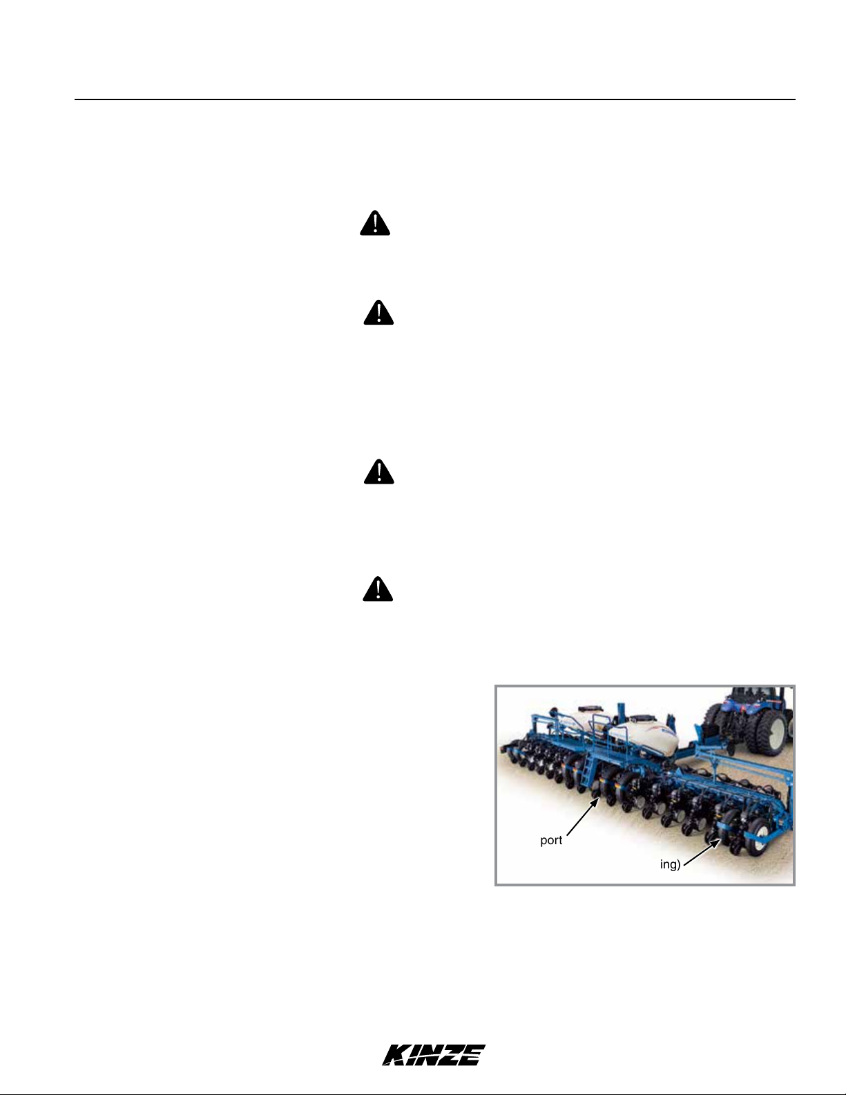
GENERAL INFORMATION
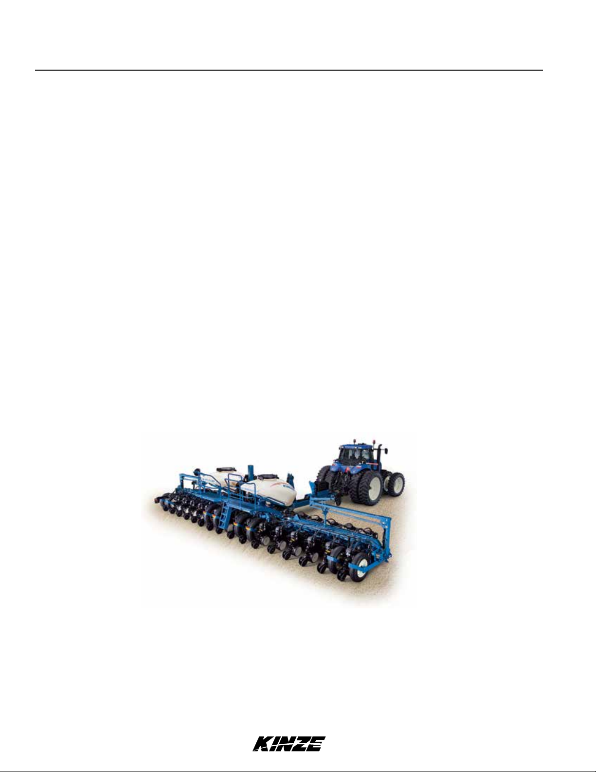
The Model 3660 Twin-Line planter is available with EdgeVac or mechanical meters, conventional hoppers or Air Seed
Delivery system (ASD), Interplant, liquid fertilizer, and various other options. Contact your Kinze Dealer for available
options and configurations.
Model 3660 12 Row ASD Planter
Information used in these instructions was current at time of printing. However, due to Kinze’s ongoing product
improvement, production changes may cause your machine to appear slightly different in detail. Kinze Manufacturing,
Inc. reserves the right to change specifications or design without notice and without incurring obligation to install the
same on machines previously manufactured.
Right hand (R.H.) and left hand (L.H.), as used throughout this manual, are determined by facing direction machine
travels in use unless otherwise stated.
1-2 Rev. 7/11
TM
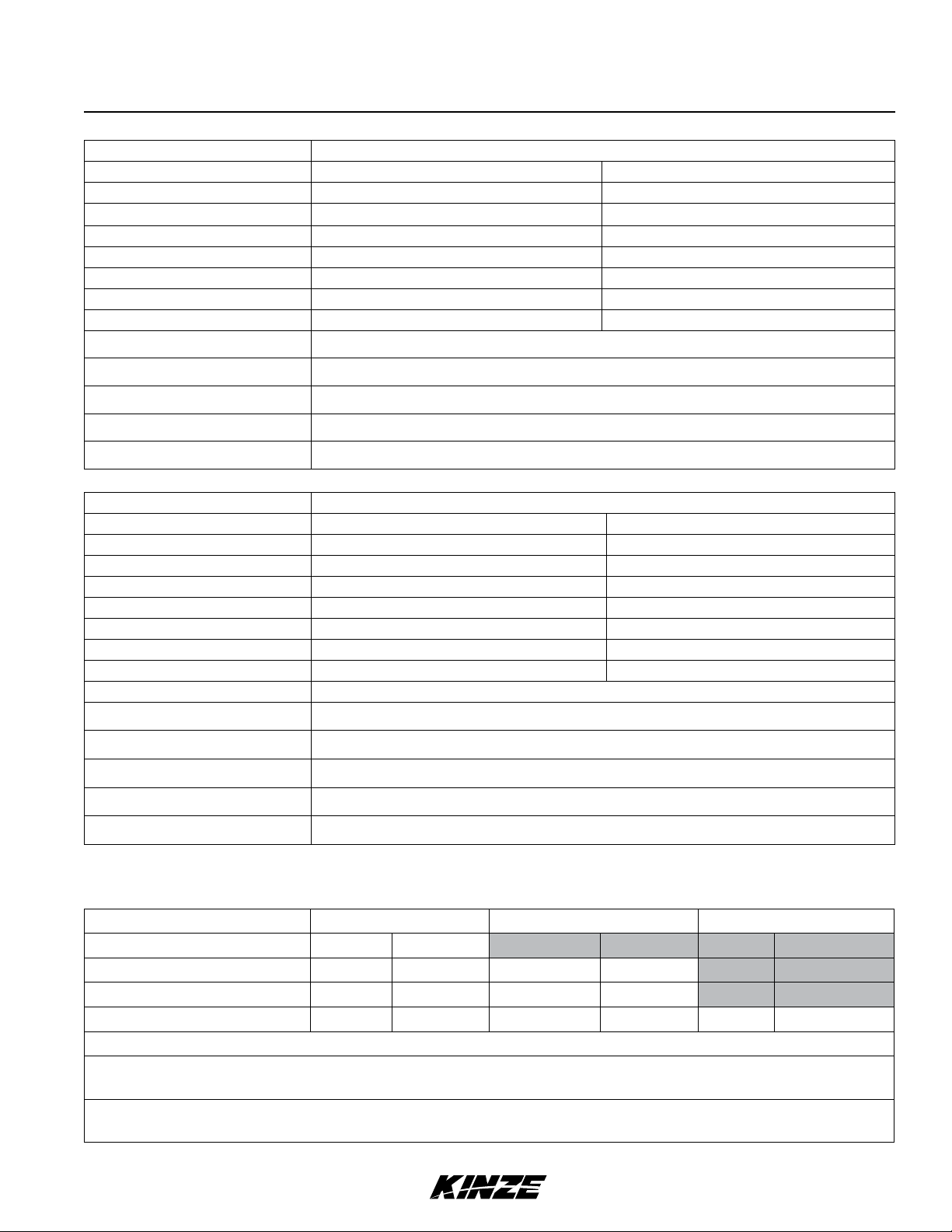
Specifications
Model 3660M0217-01
Specification Conventional Hoppers
Number of Rows 12R N 30 16R N 30
Weight Empty (Mechanical) 15,040 lb ( 6,823 kg) 18,460 lb (8,374 kg)
Weight Empty (EdgeVac) 15,450 lb (7,008 kg) 18,400 lb (8,347 kg)
Transport Height 11' 11" (3.6M) 11' 11" (3.6M)
Planting Length 23' 9" (7.2M) 26'3" (8M)
Transport Length 39' 2" (12M) 49'2" (15M)
Planting Width 32' 11" (10M) 42'11" (13.1M)
Transport Width 11' 2" (3.4M) 11'2" (3.4M)
Seed Capacity 1.75 bu. (EdgeVac / Hopper); 1.90 bu. (Mechanical / Hopper)
Transport Tire Size
Field Tire Size
Field Lift
Row Markers
Four 41" x 11" R22.5 radial load range 'H' tubeless rib implement.
7.50" x 20" 8 ply tubeless rib implement tires.
Two master center rockshaft/four wing wheel slave rephasing cylinders.
Independently controlled, three stage, low profile, w/disk blade depth bands.
Specification Air Seed Delivery (ASD)
Number of Rows 12R N 30 16R N 30
Weight Empty (Mechanical) 17,120 lb (7,766 kg) 20,020 lb (9,081 kg)
Weight Empty (EdgeVac) 17,450 lb (7,916 kg) 20,400 lb (9,254 kg)
Transport Height 12' 11" (4M) 12'11" (4M)
Planting Length 23' 9" (7.2M) 26'3" (8M)
Transport Length 39' 2" (12M) 49'2" (15M)
Panting Width 32' 11" (10M) 42'11" (13.1M)
Transport Width 11' 2" (3.4M) 11'2" (3.4M)
Seed Capacity 110 bu.
ASD Fill Height (planting position)
Transport Tire Size
Field Tire Size
Field Lift
Four 41" x 11" R22.5 radial load range 'H' tubeless rib implement.
7.50" x 20" 8 ply tubeless rib implement.
Two master center rockshaft/four wing wheel slave rephasing cylinders.
8' 5" (2.6M)
Row Markers
Independently controlled, three stage, low profile, w/disk blade depth bands.
TRACTOR HYDRAULIC REQUIREMENTS
Configuration No Optional Pumps Tractor Mounted Pump
2
Planter Mounted Pump
Mechanical Meter 3 SCV 20 gpm min.
EdgeVac Meter
1
ASD (with Mechanical Meter)
ASD (with EdgeVac)
1
External case drain required for EdgeVac hydraulic circuits when no optional pumps are used.
2
Pump PTO Requirements: Tractor mounted - 1000 rpm, 1" diameter shaft. Planter mounted - 1000 rpm, 1¾"
3
4 SCV 40 gpm min. 3 SCV 25 gpm min.
3
4 SCV 30 gpm min. 3 SCV 20 gpm min.
5 SCV 50 gpm min. 4 SCV 40 gpm min. 3 SCV 25 gpm min.
diameter shaft.
3
Tractor Horsepower Requirement: 225 horsepower or greater class tractor is required to effectively operate a fully
optioned (ASD, Interplant, EdgeVac) 3660 planter.
Rev. 7/11 1-3
TM
2

General Safety Rules
M0217-01Model 3660
1. Read and understand instructions provided in this
manual and warning labels. Review these instructions
frequently!
2. This machine is designed and built with your safety
in mind. Do not make any alterations or changes to this
machine. Any alteration to design or construction may
create safety hazards.
3. A large portion of farm accidents happen from fatigue
or carelessness. Safe and careful operation of tractor
and planter will help prevent accidents.
4.
Never allow planter to be operated by anyone
unfamiliar with operation of all functions of the unit.
Operators must read and thoroughly understand all
instructions given in this manual before operating or
working on equipment.
5. Be aware of bystanders, particularly children! Always
look around to make sure it is safe to start tow vehicle
engine or move planter. This is particularly important
with higher noise levels and quiet cabs, as you may not
hear people shouting.
6. Make sure planter weight does not exceed towing
capacity of tractor, or bridge and road limits. This is
critical to maintain safe control and prevent death or
injury, or property and equipment damage.
15. Use of aftermarket hydraulic, electric, or PTO drives
may create serious safety hazards to you and people
nearby. If you install such drives, follow all appropriate
safety standards and practices to protect you and others
near this planter from injury.
16. Follow all federal, state/provincial, and local
regulations when towing farm equipment on a public
highway. Use safety chain (not an elastic or nylon/plastic
tow strap) to retain connection between towing and
towed machines in the event of primary attaching system
separation.
17. Make sure all safety/warning lights, SMV sign, and
reflective decals are in place and working properly
before transporting the machine on public roads.
18. Limit towing speed to 15 MPH. Tow only with farm
tractor of a minimum 90 HP. Allow for unit length when
making turns.
19. Reduce speed prior to turns to avoid the risk of
overturning. Always drive at a safe speed relative to local
conditions and ensure your speed is slow enough for a
safe emergency stop.
20. Chemical application is often an integral part of
planting. Follow label instructions for proper chemical
mixing, handling and container disposal methods.
7. Never ride or allow others to ride on planter.
8. Store planter in an area away from human activity. DO
NOT permit children to play on or around the stored unit.
9. Keep hands, feet, and clothing away from moving
parts. Do not wear loose-fitting clothing which may catch
in moving parts.
10. Always wear protective clothing, shoes, gloves,
hearing, and eye protection applicable for the situation.
11. Do not allow anyone to stand between tongue or
hitch and towing vehicle when backing up to planter.
13. Prevent electrocution, other injuries, or property
and equipment damage. Watch for obstructions such as
wires, tree limbs, etc. when operating machine. Be aware
of clearances during turns and when folding/unfolding
planter.
14. Reinstall all guards removed for maintenance
activities. Never leave guards off during operation.
21. Be familiar with safety procedures for immediate first
aid should you accidentally contact chemical substances.
22. Use the proper protective clothing and safety
equipment when handling chemicals.
23. Chemicals are supplied with Material Safety Data
Sheets (MSDS) that provide full information about the
chemical, its effects on exposure, and first aid needs
in the event of an emergency. Keep your MSDS file
up-to-date and available for first responders in case of
emergency.
24. When servicing ground engaging components such
as opening disks and firming points, use special care to
avoid points and edges worn sharp during use.
25. Use professional help if you are unfamiliar with
working on hydraulic systems. Pressurized hydraulic fluid
can penetrate body tissue and result in death, serious
infection, or other injuries.
Rev. 8/11
1-4
TM

Safety Precautions
Model 3660M0217-01
Following are some common hazard warnings associated with this equipment. Pay close attention to all safety,
operating, and maintenance information in this manual and decals applied to your equipment.
DANGER!
Contacting or coming close to power lines or other high energy
sources will cause death or serious injury. Keep away from power
lines or high energy sources at all times.
WARNING
Improperly operating or working on this equipment could result in
death or serious injury. Read and follow all instructions in Operator
Manual before operating or working on this equipment.
WARNING
Falling equipment can cause death or serious injury. Install all lockup
devices or lower planter to ground before working on equipment.
WARNING
Explosive separation of rim and tire parts can cause death or serious
injury.Overination.rimandtireservicing,improperuseofrimsandtires,
or worn or improperly maintained tires could result in a tire explosion.
SAFETY SIGNS AND DECALS
WARNING
Allsafety/warninglights,reectivedecals,andSMVsignmustbe
in place and visible before transporting machine on public roads or
death, serious injury, and damage to property and equipment may
result. Check federal, state/provincial, and local regulations before
transporting equipment on public roads.
Safety signs and decals are placed on the machine to warn of hazards and provide important operating and maintenance
instructions. Information on these signs are for your personal safety and the safety of those around you. FOLLOW ALL
SAFETY INSTRUCTIONS!
• Keepsignscleansotheycanbeeasilyseen.Washwithsoapandwaterorcleaningsolutionasrequired.
• Replacesafetysignsifdamaged,paintedover,ormissing.
• CheckreectivedecalsandSMVsignperiodically.Replaceiftheyshowanylossofofreectiveproperties.
• Cleanmachinesurfacethoroughlywithsoapandwaterorcleaningsolutiontoremovealldirtandgrease
when replacing decals.
NOTE: Safety sign and decal locations are shown in the Parts Manual for this machine.
NOTE:StyleandlocationsofSMVsign,reectivedecals,andsafety/warninglightsconformto
ANSI/ASABE S279.14 JUL 2008 and ANSI/ASABE S276.6 JAN 2005.
Rev. 7/11 1-5
TM

This page intentionally left blank.
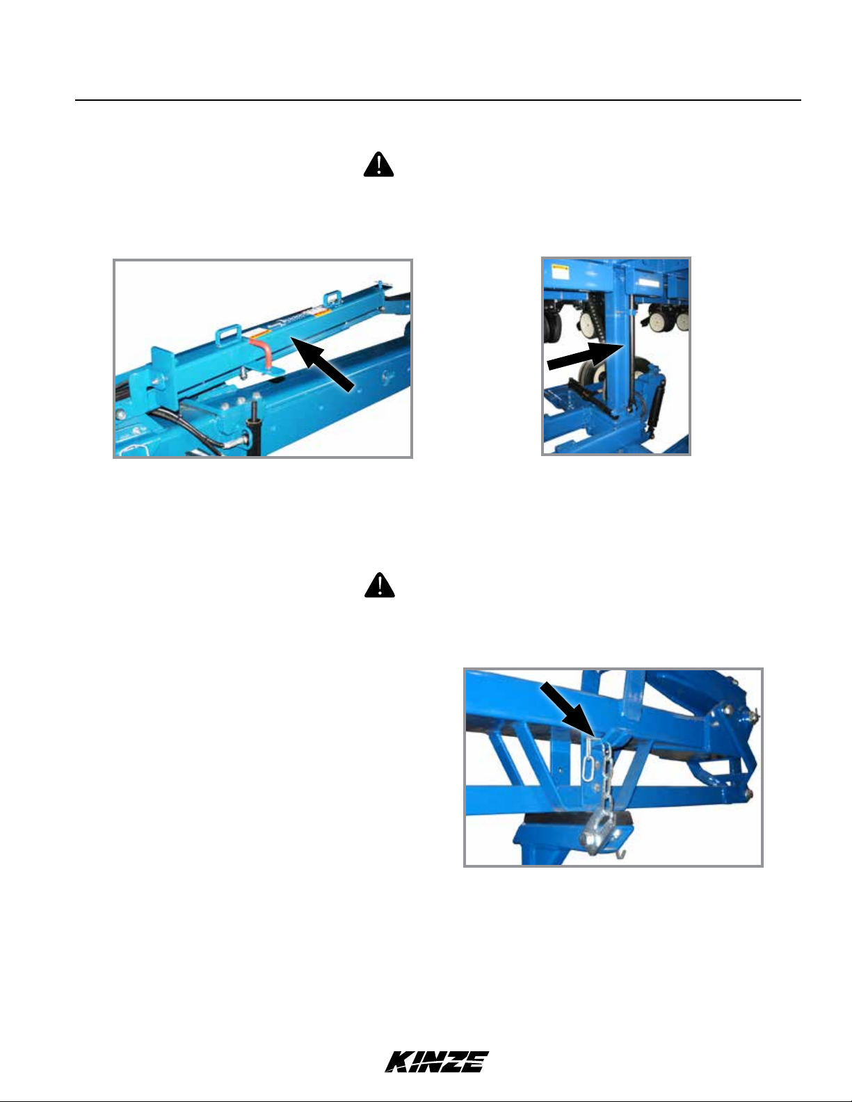
PLANTER LIFT SAFETY LOCKUP
Uncontrolled machine movement can crush or cause loss of control
resulting in death, serious injury, or damage to property and equipment.
Install all safety lockup devices before working under or transporting
this equipment.
Machine Operation
Model 3660M0217-01
WARNING
Safety lockup in storage position
Planter lift safety lockup is installed between center post and lift cylinder. It is held in place by a clevis pin near the base
of the lift cylinder rod. Remove safety lockup and store on hose take-up for field operation.
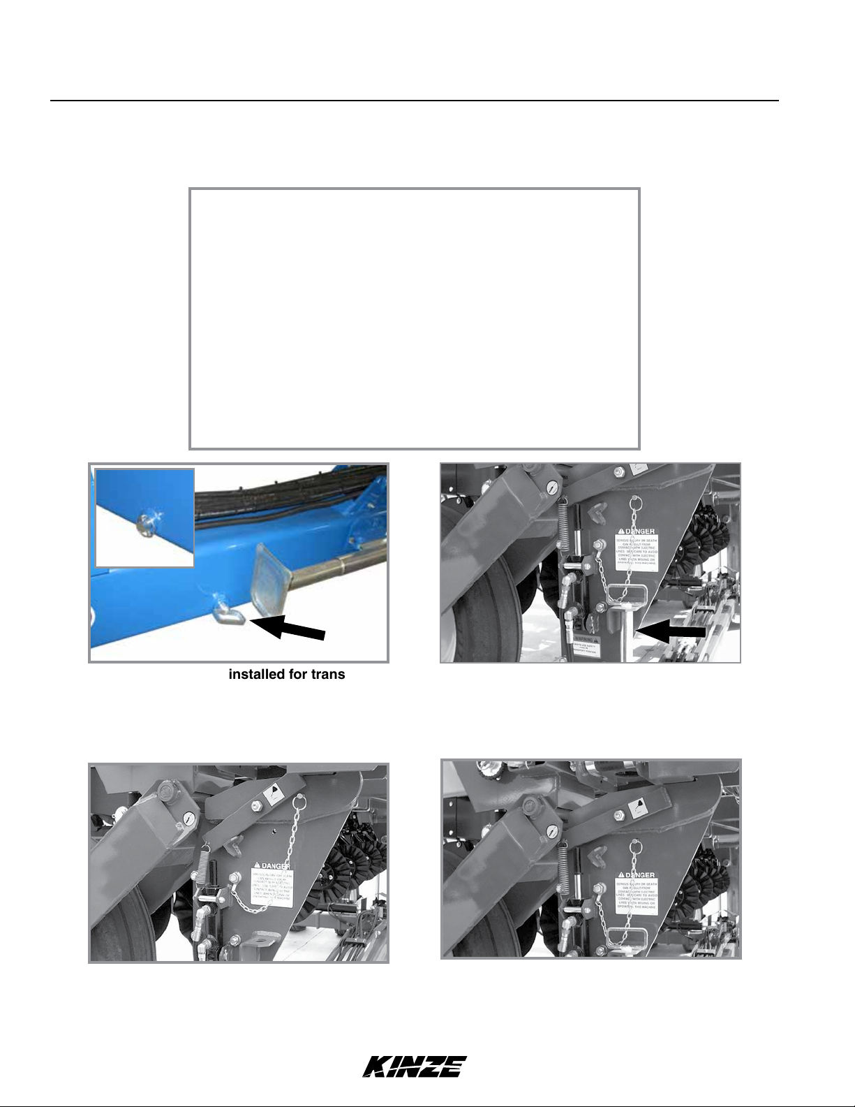
Safety lockup in transport/maintenance position
ROW MARKER SAFETY LOCKUP
WARNING
Row marker can lower at any time and could cause death or serious
injury. Stay away from row markers! Install safety lockup device when
not in use.
Always install row marker lockups when working or
transporting planter.
Connect chain between marker stand and second
stage of marker assembly.
Row marker safety lockup installed
Rev. 7/11 2-1
TM
Uncontrolled movement of equipment can cause loss of control
and could result in death, serious injury, or damage to property and
equipment. Install all safety pins before transporting equipment.
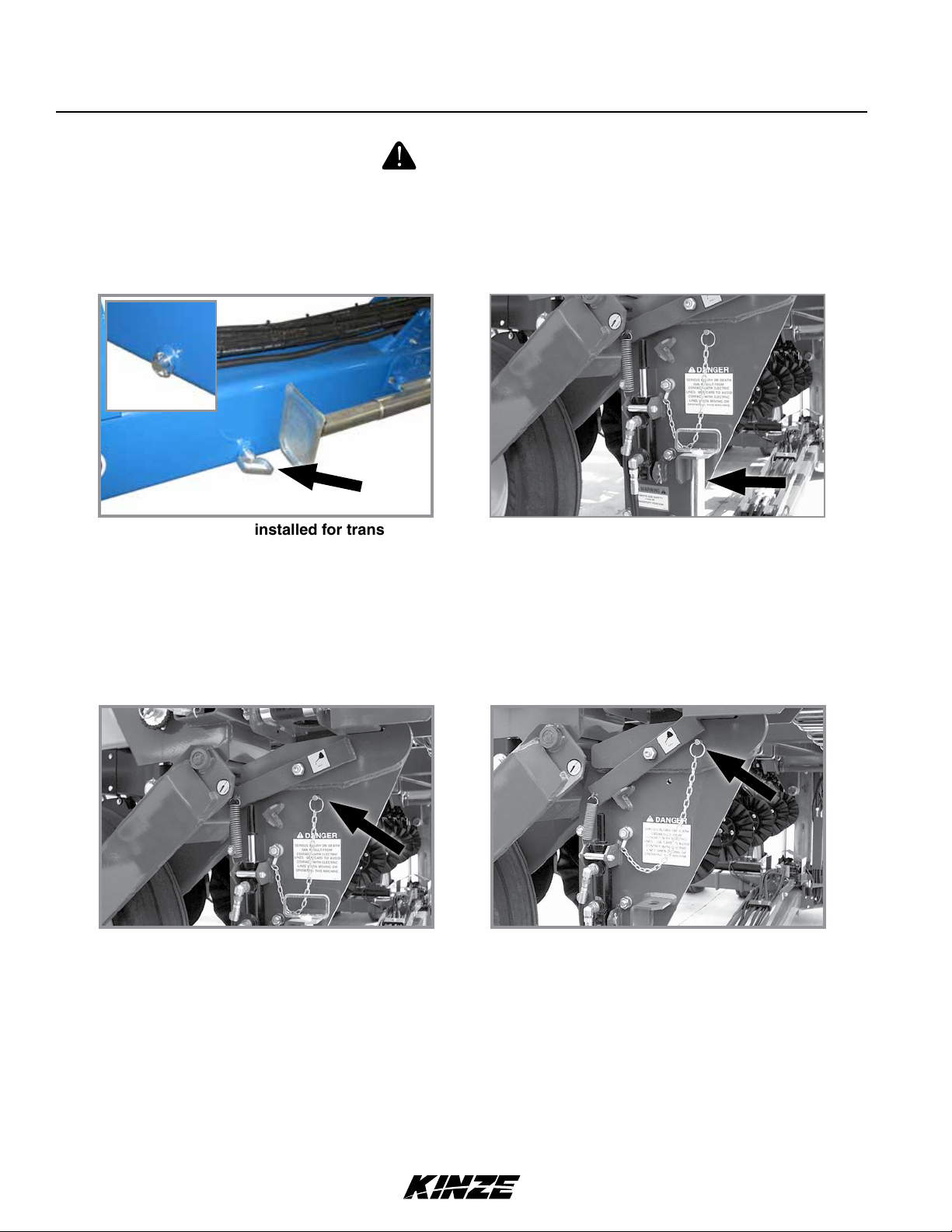
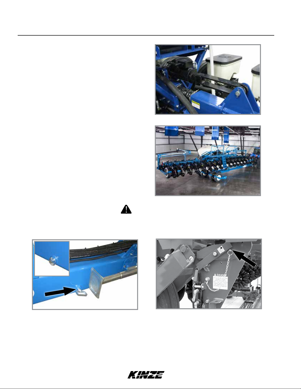
TONGUE SAFETY PIN
Snap pin
Machine Operation
M0217-01Model 3660
WARNING
Tongue safety pin installed for transport
Never transport planter without installing tongue safety pin. Tongue safety pin prevents tongue cylinder from retracting
should hydraulic failure occur or a sudden stop be made when transporting planter.
Secure safety pin in hitch with snap pin. Remove tongue safety pin and store in bracket on transport latch post at center
of planter for field operation.
Tongue safety pin stored for field operation
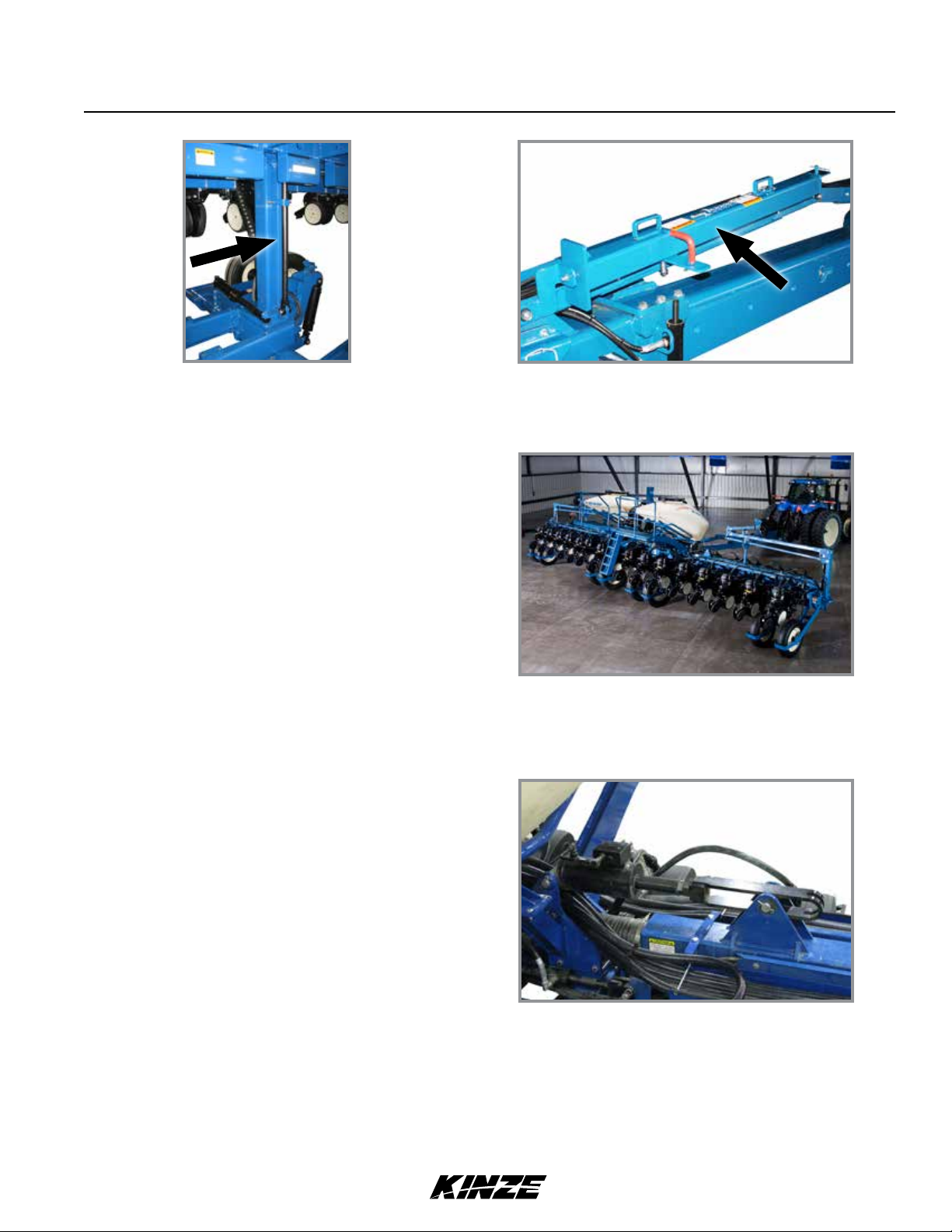
TRANSPORT LATCH LOCKING PIN
Transport latch locking pin stored
Never transport planter without installing transport latch locking pin. Transport latch locking pin prevents latch bar from
disengaging and allowing planter frame to swing away.
Transport latch locking pin installed
Remove transport latch locking pin and store in location provided on latch post for field operation.
2-2 Rev. 7/11
TM
Machine Operation
Model 3660M0217-01
INITIAL PREPARATION
Following information is general in nature to aid in preparation of tractor and planter for use, and to provide general
operating procedures. Operator experience, familiarity with the machine, and the following information should combine
for efficient planter operation and good working habits.
Improperly operating or working on this equipment could result in
death or serious injury. Read and follow all instructions in Operator
Manual before operating or working on this equipment.
WARNING
WARNING
Folding or towing planter with outer transport wheel on left side
of machine removed can cause death, serious injury, or damage
to property and equipment. Tipping may occur because of narrow
wheel base. Outer transport wheel on left side of machine is shipped
removed on non-ASD planters (not bolted on) to allow narrower
width truck shipment. DO NOT REMOVE THIS ASSEMBLY AFTER
PLANTER IS ASSEMBLED FOR USE.
WARNING
Loose transport wheel lug bolts can result in wheel separation from
planter and cause death, serious injury, and damage to property and
equipment. Torque transport wheel 5⁄8"- 18 lug bolts to 180 ft-lb (244
N-m) before operating planter for the first time and periodically after.
WARNING
Explosive separation of rim and tire can cause death or serious injury.
Overination,rimandtireservicing,improperuseofrimsandtires,
worn, or improperly maintained tires could result in a tire explosion.
1. Torque transport wheel "- 18 lug nuts to 180 ft-lb (244 N-m).
2. Inflate tires to the following specifications:
Transport (center section) 255-70R 22.5 (“224” rim)
75 psi (517.1 kPa) recommended/75 psi (517.1 kPa) max.
Transport (center section) 255-70R 22.5" (“276” rim)
75 psi (517.1 kPa) recommended/100 psi (689.4 kPa) max.
Ground drive (wings) 7.50" x 20" 40 psi (275.7 kPa)
Liquid fertilizer piston pump 7.60" x 15" 40 psi (275.7 kPa)
3. Lubricate planter and row units following instructions in Lubrication and Maintenance section of this manual.
4. Check all row unit drive chains for proper tension, alignment, and lubrication.
Rev. 7/11 2-3
Transport
Ground drive (wing)
Tire locations
TM

Machine Operation
M0217-01Model 3660
TRACTOR MOUNTED PTO PUMP AND OIL COOLER OPTION
Tractor driven PTO pump and oil cooler option is for tractors with less than required hydraulic output needed to
operate hydraulic-driven vacuum fan and other planter hydraulic requirements.
A 1000 RPM PTO is required to operate PTO-driven hydraulic pump.
Option consists of a 1"-21 or 1¾"-20 spline,13.5 GPM 2000 PSI tractor mounted pump, 10 gallon capacity hydraulic
reservoir, 15 GPM-rated oil cooler, spin-on 10-micron oil filter, and required hydraulic valves and fittings.
Reservoir
Flow control valve
Oil filter
Hydraulic reservoir assembly
NOTICE
Clean and grease PTO shaft coupling with high-pressure
industrial coupling grease (Chevron coupling grease
or equivilant) meeting AGMA CG-1 and CG-2 Standards
each time driveshaft is installed or premature wear and
equipment failure can occur.
Chevron® trademark is owned by Chevron Products Company.
AGMA is the acronym for American Gear Manufacturers
Association.
Oil cooler
Hydraulic
motor
Vacuum fan assembly
Tractor mounted PTO pump
(1" spline PTO pump shown)
2-4 Rev. 7/11
TM
Machine Operation
Model 3660M0217-01
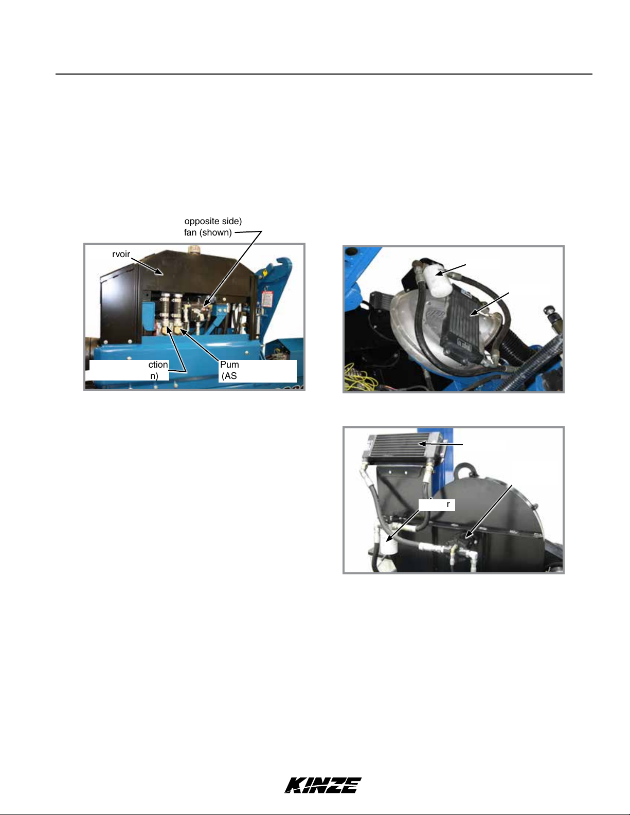
PLANTER MOUNTED PTO PUMP AND OIL COOLER OPTION
Planter mounted PTO pump drive with oil coolers option is for tractors with less than required hydraulic output
needed to operate hydraulically driven vacuum and pressure fans and other planter hydraulic requirements.
A 1¾"–20 spline 1000 rpm PTO is required to operate planter mounted hydraulic pumps.
Option consists of a PTO driveshaft, 13.5 gpm/2000 psi two-section pump, 10 gallon hydraulic oil reservoir, two oil
coolers, two spin-on 10-micron oil filters, and required valves and fittings.
Flow control valve - ASD fan (opposite side)
Flow control valve - EdgeVac fan (shown)
Reservoir
Pump front section
(EdgeVac fan)
Pump rear section
(ASD system fan)
PTO pumps and reservoir assembly
NOTICE
Clean and grease PTO shaft coupling with high-pressure
industrial coupling grease (Chevron coupling grease
or equivilant) meeting AGMA CG-1 and CG-2 Standards
each time driveshaft is installed or premature wear and
equipment failure can occur.
Chevron® trademark is owned by Chevron Products Company.
AGMA is the acronym for American Gear Manufacturers
Association.
Oil filter
Oil cooler
ASD fan assembly
Oil cooler
Hydraulic
motor
Oil filter
Vacuum fan assembly
TRACTOR REQUIREMENTS
Consult your dealer for information on horsepower requirements and tractor compatibility. Requirements vary with
planter options, tillage, and terrain.
A 12 volt DC electrical system is required on all sizes.
Rev. 7/11 2-5
TM
Machine Operation
M0217-01Model 3660
TRACTOR PREPARATION AND HOOKUP
1.
Adjust tractor drawbar 13-17 inches above ground with hitch pin hole directly below PTO shaft center line. Make
sure drawbar is in a stationary position.
2. Install control console on tractor in a convenient location within easy reach of operator and close to hydraulic
controls. Mount control console securely and route power cord to power source. Control console operates on
12 volt DC only. If two 12 volt batteries are connected in series, ALWAYS make power connection on battery
grounded to tractor chassis.
If two 6 volt batteries are connected in series, make sure power connection provides 12 volt DC across positive
terminal on one battery and negative terminal of second battery.
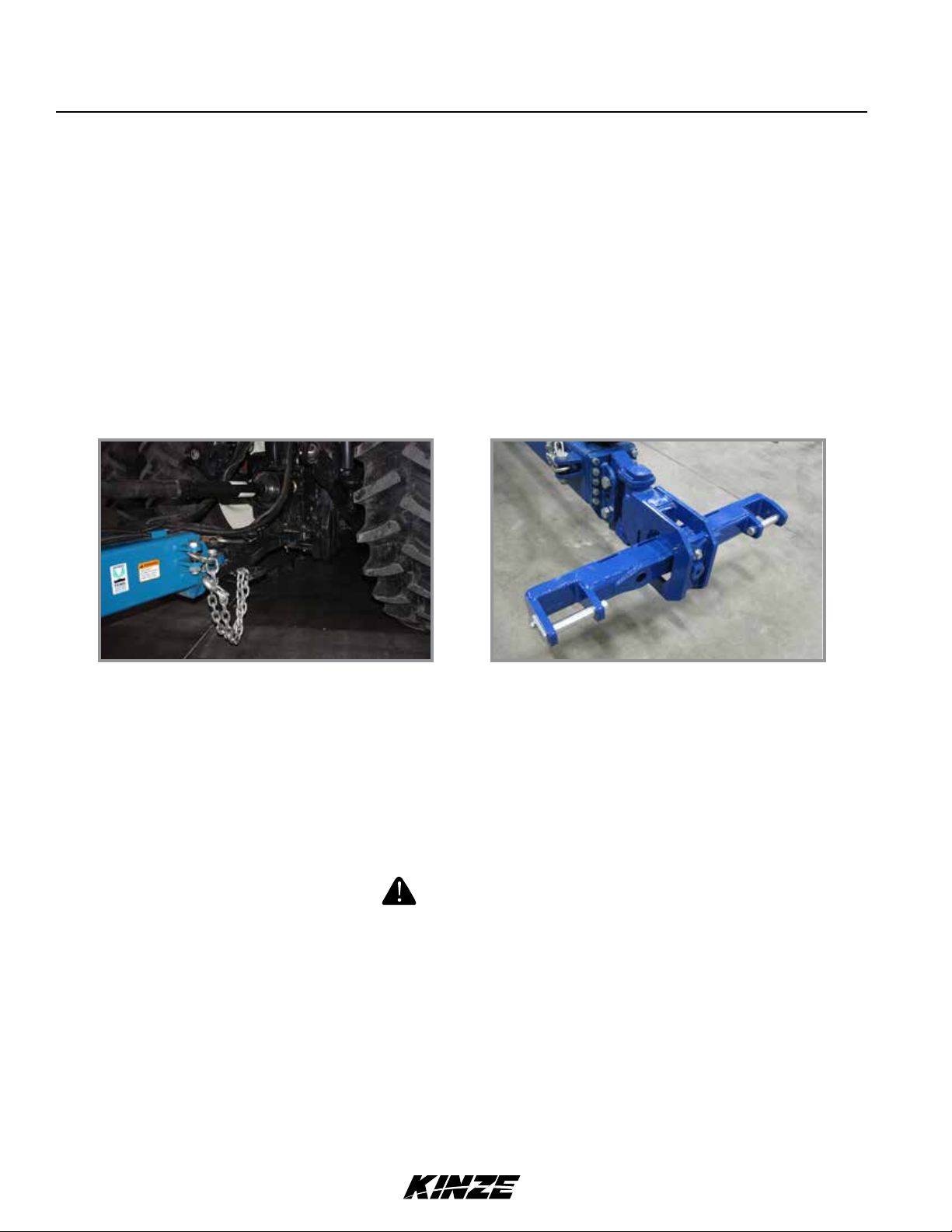
3. Back tractor to planter and connect with 1¼" - 1½" diameter hitch pin. If tractor is not equipped with a hitch pin
locking device, make sure hitch pin is secured with a locking pin or cotter pin.
Planter/safety chain hookup to tractor Optional 2-point hitch
NOTE: DO NOT install safety chain using clevis mounting hardware. Safety chain MUST be installed
separately.
4. Safety chain must be used to keep planter and tractor connected in case of a hitch pin/drawbar failure. Attach
safety chain at an unused clevis mounting hole on the planter hitch. Torque hardware to 840 ft-lb (1138.8 N-m).
NOTE: A 2-Point Hitch Option converts planter from drawn to semi-mounted and is available for use with
Category 3N or 3 three-point hitch designs. Safety chain is not used with 2-point hitch.
WARNING
Pressurizedhydraulicuidcanpenetratebodytissueandresultin
death, serious infection, or other injuries. Fluid injected under skin
must be IMMEDIATELY removed by a surgeon familiar with this
type of injury. Make sure connections are tight and hoses and
fittings are not damaged before applying system pressure. Leaks
can be invisible. Keep away from suspected leaks. Relieve pressure
before connecting or disconnecting tractor, searching for leaks, or
performing any system maintenance.
NOTICE
Wipe hose ends to remove any dirt before connecting couplers to
tractor ports or contamination may cause equipment failure.
2-6 Rev. 7/11
TM
Machine Operation
5. Connect hydraulic hoses to tractor ports in a sequence familiar and comfortable to the operator.
NOTICE
Connect hydraulic motor case drain to a case drain return line with
zero PSI on tractor. Failure to connect to a return with zero PSI will
cause hydraulic motor shaft seal damage. DO NOT connect hydraulic
motor case drain to a SCV outlet or motor return circuit connection.
Contact tractor manufacturer for specific details on “zero pressure
return”.
NOTICE
Always connect hydraulic motor return hose to tractor motor return
port. Do not connect to tractor SCV unless through a motor spool
or hydraulic motor failure can occur. If a motor return port is not
available on the tractor, the SCV controlling the ASD system MUST
beintheoatpositionbeforeplanterismovedinplantingoreld
raised position when ASD system is not in use.
PLANTER TO TRACTOR HYDRAULIC CONNECTIONS
Color/Label Machine
Function
Red AA Field Lift ½" Pressure
Red BB ½" Return
Blue AA Planter Fold & Row Marker " Return
Blue BB " Pressure
Black RR Seed Rate Hydraulic Drive
Black PP ½" Pressure
(EdgeVac)
Black RR Seed Rate Hydraulic Drive (Mechanical) ½" Return
Black PP " Pressure
Green RR EdgeVac Vacuum Fan ¾" Return
Green PP ½" Pressure
Orange CD
Hose Size Function
¾" Return
" Case Drain
Model 3660M0217-01
Yellow RR ASD System Pressure Fan ¾" Motor Return
Yellow PP ½" Pressure
Orange CD
" Case Drain
NOTE:Setadjustableowoutlet(SCV)tofullowposition.
For tractors not equipped with a method for finite adjustment of
hydraulicow,FlowControlNeedleValveKitG1K426isavailable
from Kinze Repair Parts through your Kinze Dealer.
G1K426 needle valve kit
Rev. 7/11 2-7
TM
Machine Operation
M0217-01Model 3660
6. Connect ASABE Standards 7 terminal connector for safety/warning lights on planter to ASABE Standards
receptacle on tractor. If your tractor is not equipped with an ASABE Standards receptacle, check with your tractor
manufacturer for availability. Check warning lights on planter work in conjunction with warning lights on tractor.
NOTE: A 12 volt battery connection is required to power the vacuum fan digital gauge. Connect “red” wire to
positive (+) battery terminal and “black” wire to negative (-) battery terminal.
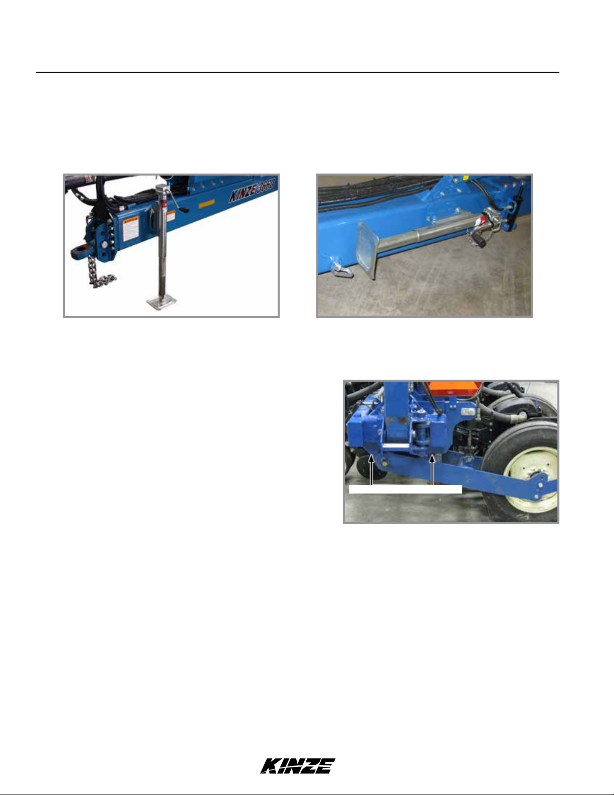
Jack in operating position Jack in storage position
7. Raise jack stand and remount horizontally on storage bracket on opposite side of hitch.
LEVEL PLANTER
Lateral adjustment is maintained by tire pressure. Check tires
are inflated to specification.
Front and rear level adjustment is maintained by hitch clevis
position unless tractor drawbar is adjustable for height. Planter
frame and row unit parallel arms must be level for proper
planter and row unit operation. Bottom of toolbar should be 20"
to 22" from planting surface.
1. Lower planter to planting position and check planter is level
front to rear. Go to step 2 if hitch is too high or low.
NOTE: DO NOT install safety chain using clevis hardware. Move safety chain location if necessary.
2. Remove clevis hitch hex head cap screw and lock nut using a torque wrench. Replace if off-torque is below 75 ft-lb
(101.6 N-m) or there is corrosion or damage.
NOTE: Clevis must be free to move on hitch. DO NOT OVERTIGHTEN hardware.
Level 20" - 22" from ground
Level planter toolbars
3. Align clevis to hitch holes at new location and install hex head cap screw and lock nut. Tighten lock nut until
threads are fully engaged and hex head cap screw and lock nut are firmly against hitch bracket.
NOTE: On planters with push row units and no till coulters, uplift from down force springs or air springs in
pneumatic down pressure system may cause wings to rise slightly in planting position. Problem may be
compounded if static pressure is trapped in planter’s hydraulic lift system which can cause wing cylinders
toextendslightly.Operatingtractor’shydraulicsysteminoatpositionormovingtractor’shydraulicleverto
oatpositionbrieytorelievepressurewillhelpmaintainpropertoolbarheight.
2-8 Rev. 7/11
TM
Machine Operation
Model 3660M0217-01
4. Field check planter.
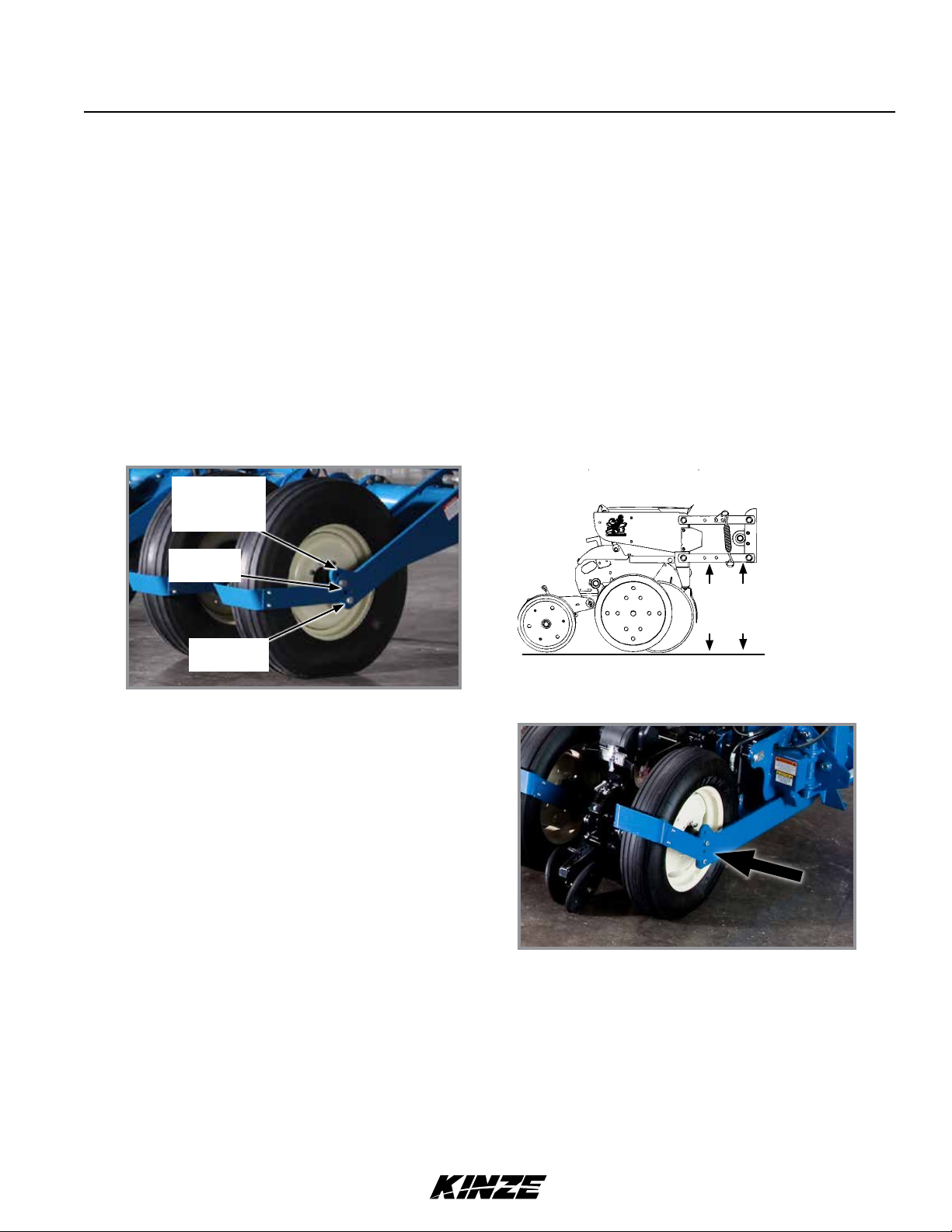
Field and actual planting conditions dictate which transport wheel setting to use so row unit parallel arms are parallel
with ground. It may be necessary to lower ground drive wheels to ensure level lateral toolbar operation if transport
wheels are set in one of the two lower sets of holes. Make a field check when planter is fully loaded with seed,
granular chemicals, fertilizer, etc. to be sure wings are level with center frame. If wings are not level with center frame,
drive wheels and/or transport wheels can be raised or lowered in wheel arms to increase or decrease planter toolbar
height. Raise hitch to ensure level operation.
NOTICE
Component interference can damage equipment. Check clearance
between tires and drill shaft U-joint when using top hole setting.
NOTE: To allow adequate drive force after lowering ground drive wheels, it may be necessary to lower
contact drive wheel arms to lower sets of holes in wheel modules and lower down pressure springs to lower
mounting rods on wheel modules.
No till or firm
soil conditions.
(Initial setting)
Soft field
conditions.
Ridge or
bed planting.
Transport wheel adjustment
Keep row unit parallel arms parallel to
ground when adjusting wheel heights.
Parallel
with
ground
Field/wing wheel adjustment
RIDGE PLANTING
Move drive and transport wheels 2" or 4" to lower mounting holes in wheel arms when ridge planting to increase
planter toolbar height. Raise hitch height to ensure level operation.
Rev. 7/11 2-9
TM

Machine Operation
M0217-01Model 3660
CONTROL CONSOLE OPERATION
Tractor’s hydraulic system and planter control console are used to raise and lower planter, rotate frame, extend and
retract tongue, lock and release wings, and operate row markers.
DANGER!
Contacting or coming close to power lines or other high energy
sources will cause death or serious injury. Keep away from power
lines or high energy sources at all times.
WARNING
Being struck by a moving marker can cause death or serious injury.
Markers can move unexpectedly when SCV controls are operated.
Keep marker switch OFF when not in use.
NOTICE
Control console face is backlit with a power switch on back side.
Turn off console when not in use or tractor battery will drain.
Marker switch is an ON/OFF/ON type to select right or left
hand marker operation. It is disabled when a planter fold
function is selected. An indicator light illuminates when switch
is ON.
Raise/wing lock and rotate/tongue switches are MOMENTARY
ON/OFF/MOMEMENTARY ON type to select a planter fold
function. They must be held in position while operating tractor
SCV control for desired function to operate.
Down pressure switch is a MOMENTARY ON/OFF/
MOMENTARY ON type used to increase or decrease row unit
down pressure.
Work light switch is on ON/OFF type to control optional planter mounted work lights.
Point row switches are not used on Model 3660 planter. This function is controlled by Kinze Vision or Cobalt planter
controller.
A 50 amp main control box fuse and 20 amp delayed air compressor fuse are located on control box front lower left
face.
NOTE: Hydraulic weight transfer toolbar operates when planter is in motion and hydraulic seed rate drive is
operating.
Model 3660 control box
Model 3660 planters operate using three to five dual remote (SCV) hydraulic outlets:
1. Raise and lower planter during field operation with axle rockshaft (field lift).
2. In conjuction with control console switches, controls row markers, center post, wing locks, rotation, and tongue
extension.
3. Hydraulic seed rate drive.
4. EdgeVac blower drive (optional).
5. Air Seed Delivery blower drive (optional).
2-10 Rev. 7/11
TM
Machine Operation
Model 3660M0217-01
HYDRAULIC SEED RATE DRIVE
Refer to Ag Leader Integra or Kinze Cobalt operation manuals for information on setting and controlling hydraulic seed
rate system.
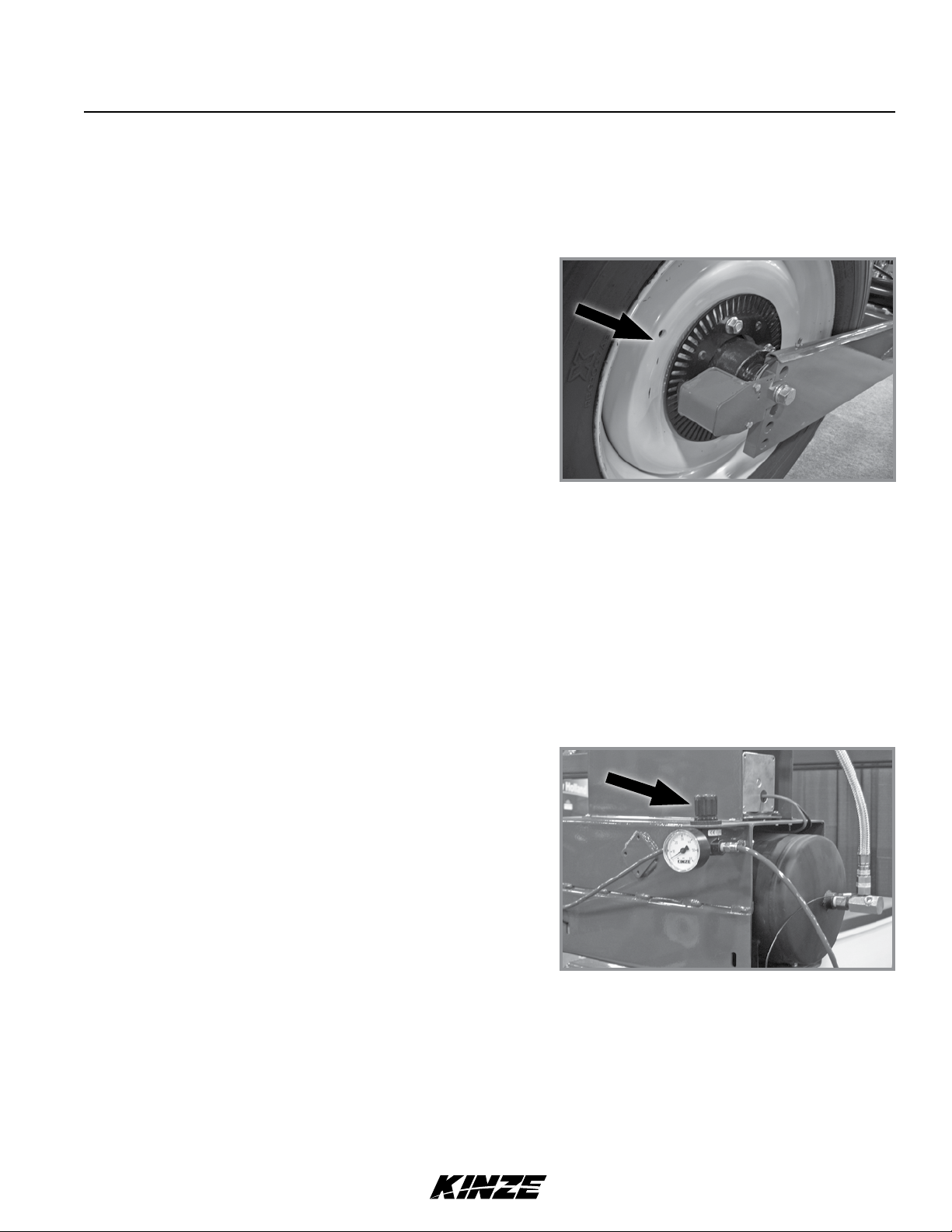
HALL EFFECT SENSOR (Hydraulic Drive Only)
Set Hall effect sensor within " of pick-up disc.
Hall effect sensor
HYDRAULIC WEIGHT TRANSFER TOOLBAR
The hydraulic weight transfer system is standard. The hydraulic drive system powers the hydraulic weight transfer
system. Pressure is set from the factory and does not require additional adjustment.
ROW UNIT AIR CLUTCHES
Set air clutch system pressure to 50 psi (344.7 kPa).
Air clutch pressure valve
AG LEADER ELECTRIC CLUTCHES
Electric clutches along with GPS can stop seed flow by turning off seed meters (and planter sections) based on field
mapping and previously planted areas.
Rev. 7/13 2-11
TM
Machine Operation
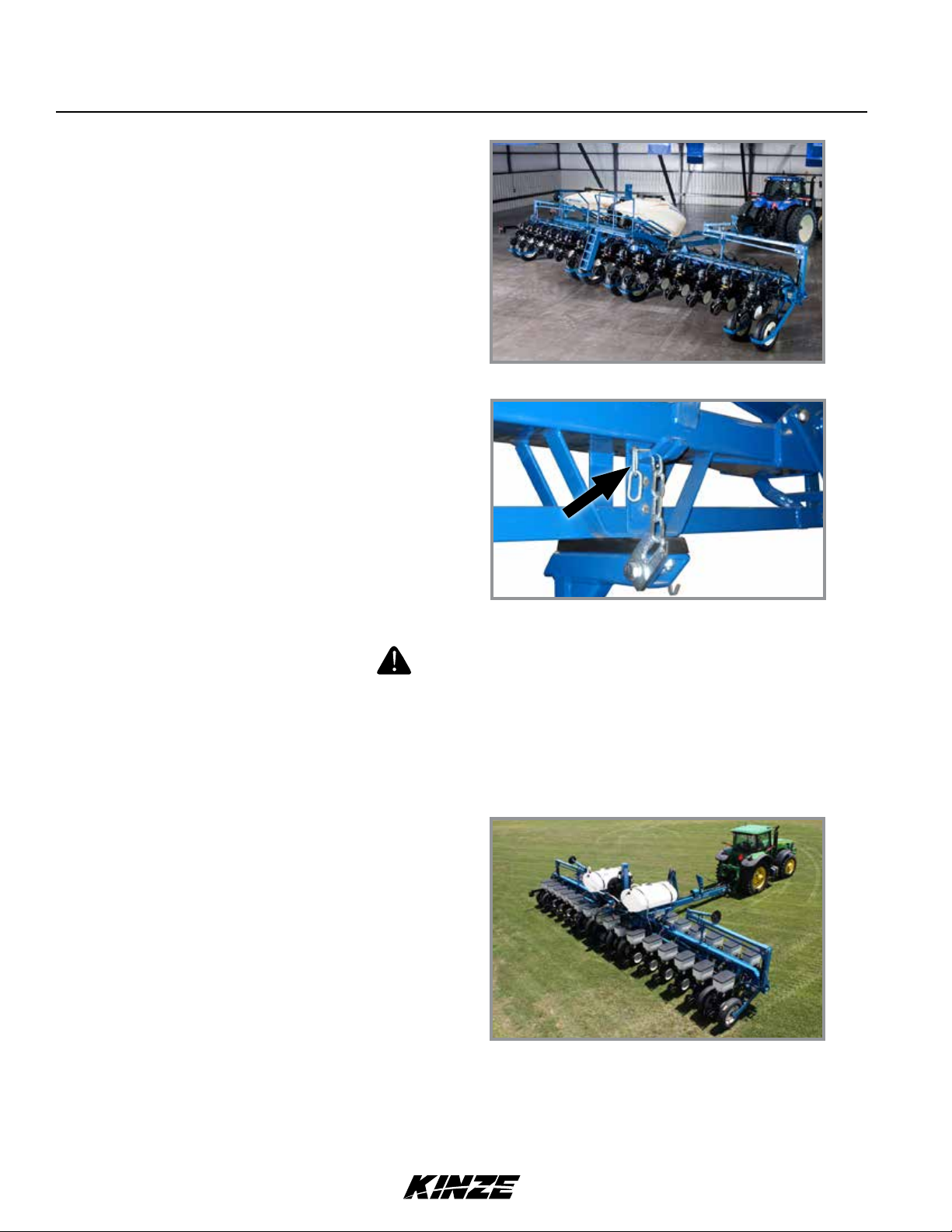
TRANSPORT TO FIELD SEQUENCE
Position planter in a relatively flat open area. Avoid an area with furrows, etc.
SUMMARIZED TRANSPORT TO FIELD SEQUENCE
1. Remove and store tongue safety pin.
2. Remove and store transport latch locking pin.
3. Remove and store safety lockup.
4. Rotate planter to field position.
5. Lower planter on center post.
6. Raise planter using field lift.
7. Release wing locks.
8. Retract tongue.
9. Lower planter to ground.
10. Remove row marker lockups.
NOTE: Read following information for detailed instructions.
M0217-01Model 3660
Snap pin
Tongue safety pin installed for transport
Tongue safety pin stored for field operation
1. With tongue fully extended, planter in transport position, and tractor shut down; remove tongue safety pin and place
it in storage position.
Transport latch locking pin
Locked transport position
Transport latch locking pin
Storage position
2. Remove transport latch locking pin from locked position and place it in storage location.
Rev. 9/11
2-12
TM
Machine Operation
Safety lockup in storage positionSafety lockup in transport position
3. Remove safety lockup from center lift cylinder and place in storage location on hose take-up.
4. Start up tractor. Hold rotate/tongue switch
to ROTATE and operate hydraulic control to
rotate planter to field position. Transport latch will
automatically release.
Model 3660M0217-01
NOTE: Center post lift is used only for folding or
unfolding planter. Raising and lowering planter
during field operation is performed using field lift
(axle rockshaft).
5. Hold raise/wing lock switch to RAISE and operate
hydraulic control to fully lower planter on center
post.
6. Operate hydraulic control to raise planter using field lift.
7. Hold raise/wing lock switch to WING LOCK and
operate hydraulic control to release wing locks.
Planter in field lift position
Wing lock release
Rev. 9/11 2-13
TM
Machine Operation
8. Operate hydraulic control to raise planter using
field lift.
9. Hold rotate/tongue switch to TONGUE and operate
hydraulic control to fully retract tongue. Tongue latch
automatically engages.
10. Remove row marker lockups.
M0217-01Model 3660
Field lift/tongue retraction
FIELD OPERATION
DANGER!
Contacting or coming close to power lines or other high energy
sources will cause death or serious injury. Keep away from power
lines or high energy sources at all times.
Raise planter out of ground when making sharp turns or backing up
or equipment damage may result.
Raising and lowering planter is performed using field
lift (axle rockshaft) during field operation.
NOTE: Field lift cylinders are rephasing cylinders
and it is necessary to fully lower planter to rephase
them. Cylinder stops can not be used.
Row marker lockup
NOTICE
Planting position
PLANTING SPEED
Planters are designed to operate in a speed range of 2 to 8 mph (3.2 - 12.9 kph). Higher ground speeds generally cause
more variation in seed spacing. Speeds above 5.5 mph (8.8 kph) are typically not recommended.
Rev. 9/11
2-14
TM
Machine Operation
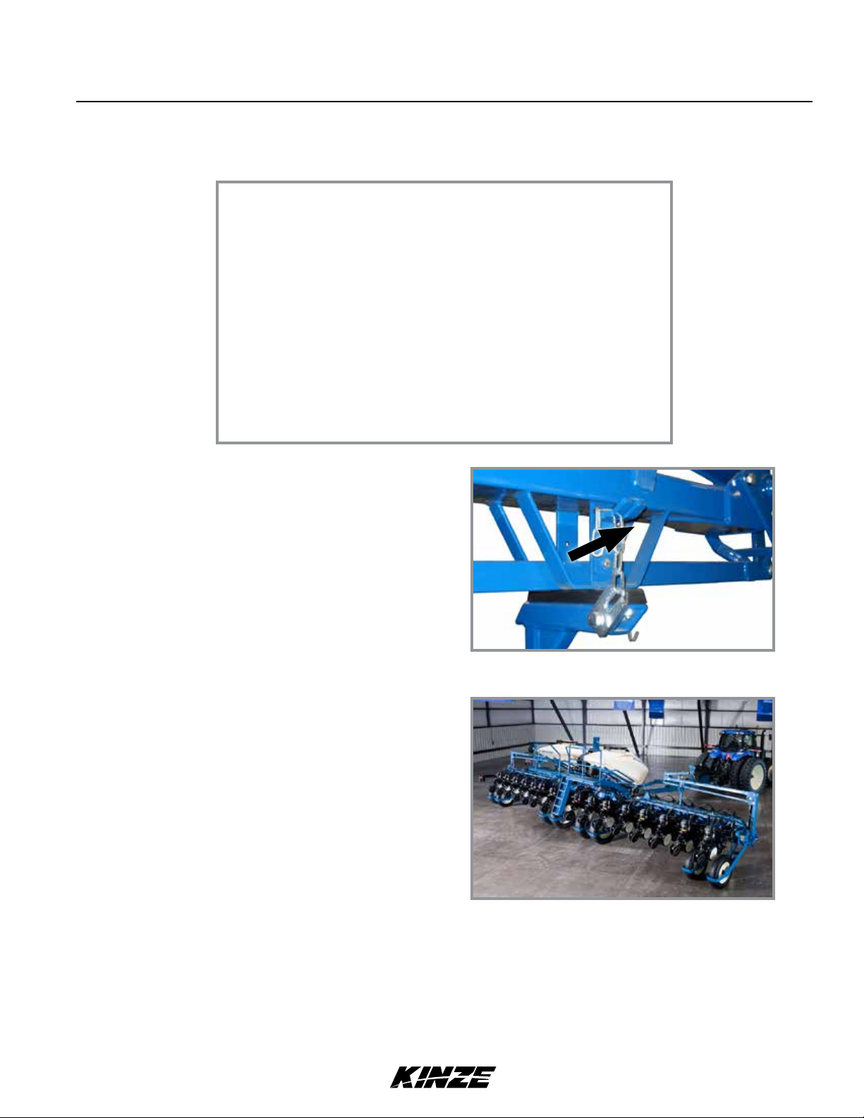
FIELD TO TRANSPORT SEQUENCE
Position planter in a relatively flat area. Avoid areas with furrows, etc.
SUMMARIZED FIELD TO TRANSPORT SEQUENCE
1. Install row marker lockups.
2. Raise planter using field lift.
3. Extend tongue.
4. Engage wing locks.
5. Lower planter to ground.
6. Raise planter on center post.
7. Rotate planter to transport position.
8. Install safety lockup.
9. Install hitch safety pin.
10. Install transport latch locking pin.
NOTE: Read following information for detailed instructions.
Model 3660M0217-01
1. Install row marker lockups.
2. Start tractor. Operate hydraulic control to raise
planter using field lift.
3. Hold rotate/tongue switch to TONGUE and operate
hydraulic control to fully extend tongue. Tongue
latch automatically engages.
Row marker lockup
Field lift/tongue extension
Rev. 9/11 2-15
TM
Machine Operation
4. Hold raise/wing lock switch to WING LOCK and
operate hydraulic control to engage wing locks.
5. Operate hydraulic control to lower planter using
field lift.
6. Hold raise/wing lock switch to RAISE and operate
hydraulic control to fully raise planter on center
post.
7. Hold rotate/tongue switch to ROTATE and operate
hydraulic control to rotate planter to transport
position. Transport latch automatically engages.
M0217-01Model 3660
Wing lock engaged
Transport position
WARNING
Uncontrolled movement of equipment can cause loss of control
and could result in death, serious injury, or damage to property and
equipment. Install all safety pins before transporting equipment.
Snap pin
Tongue safety pin installed
8. Shut down tractor and remove safety lockup from storage location on hose take-up. Install safety lockup at center
post as shown. Make sure top latch is around cylinder rod and fastened with safety pin, and that lower end is
secured with detent pin.
Transport latch locking pin installed
9. Remove hitch safety pin from storage location and install in hitch.
10. Remove transport latch locking pin from storage location and install in transport latch.
Rev. 9/11
2-16
TM

Machine Operation
Model 3660M0217-01
EDGEVAC SYSTEM
Kinze EdgeVac seed metering system includes seed meters, seed discs, and an air system consisting of a hydraulic
driven vacuum fan which draws air through manifolds, hoses, and seed meters on each row unit.
WARNING
Moving fan blades can cause amputation or severe injury. Never
operate vacuum fan with cover removed.
DIGITAL VACUUM READOUT
Digital vacuum readout is incorporated into Kinze Vision and Cobalt displays. Refer to their operation manuals for
instructions.
VACUUM FAN MOTOR VALVE BLOCK ASSEMBLY
A pressure relief valve in the hydraulic circuit prevents build up of oil pressure over 35 PSI in case drain line when
vacuum fan motor is operating. This valve will vent oil outside valve block through a drain hole in the aluminum valve
block. This can occur whenever case drain is improperly connected or pressure in motor circuit builds.
See “Hydraulic Diagram - Vacuum Fan Motor System” in Lubrication and Maintenance section.
Valve block contains a check valve that prevents vacuum fan from operating in wrong direction if pressure is applied to
return side of motor and allows fan to coast to a stop when tractor hydraulic control is returned to neutral position.
NOTE: Fan turns at a reduced speed If reverse pressure is applied.
ANALOG VACUUM OR PRESSURE GAUGE
The analog vacuum or pressure gauge connects directly to the
EdgeVac (vacuum) or ASD (pressure) manifold and is teed into
the digital sending units.
Only adjustment is to “zero” needle with no vacuum or
pressure present. If there is a significant difference between
gauge and a reading taken at meters, a different manifold
location should be found to connect hose to gauge and digital
sending unit.
Analog gauge
NOTE: Analog gauges are identical EXCEPT for plug and hose barb locations in side of gauge housing.
DO NOT connect EdgeVac or ASD hose to wrong gauge. Check plug and hose barb installation if readout is
erratic or appears inaccurate.
Rev. 7/11 2-17
TM
Machine Operation
AIR SEED DELIVERY (ASD) SYSTEM
CAUTION
Seedyingoutofdisconnecteddeliverytubeathighvelocitycancause
injury. Do not disconnect delivery tubes when system is operating.
NOTICE
Foreign materials can plug system. Make sure seed is clean and
free of debris when filling ASD hoppers.
NOTICE
Do not turn on system with tractor engine at full speed or system
damage may occur.
NOTICE
Do not operate ASD system above maximum system operating
pressure of 20 inches of water or seed bridging may occur.
1. Before filling hoppers refer to “Row Unit Operation” for
additives information. Fill hoppers with seed, latch lids,
and secure with pin.
M0217-01Model 3660
2. Start air seed delivery system with tractor engine at idle.
3. Increase engine speed to full and set initial system
pressure using flow control valve.
4. Allow system to warm up and adjust pressure if necessary.
Recommended pressures:
• Corn – 12 inches of water
• Soybeans – 10 inches of water
• Actual pressure needed is affected by seed size, shape, and coating.
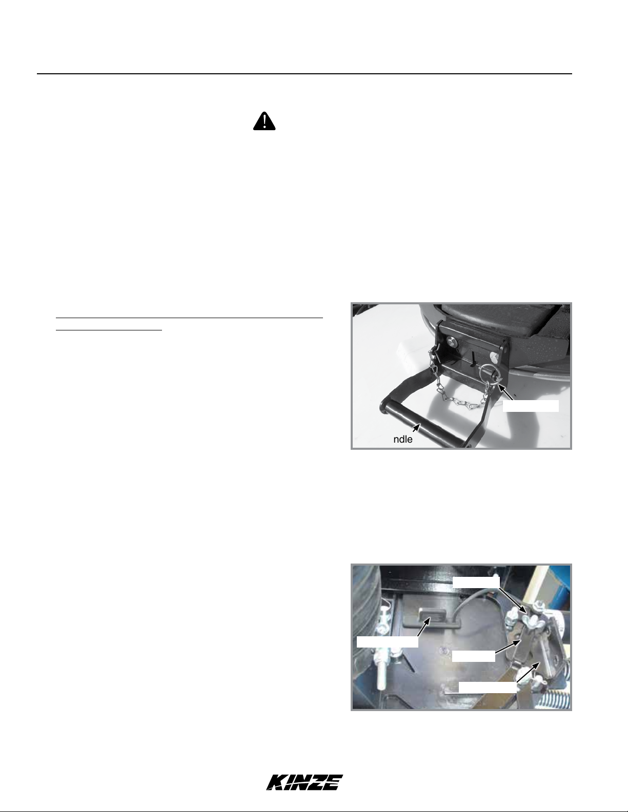
ASD ENTRAINER ACCESS
1. Shut down ASD system.
2. Loosen wing nut and turn retainer holding shutoff door
in its storage location.
3. Remove rubber plug closest to area in entrainer needing
attention.
Pin w/chain
Latch handle
ASD tank lid latch
Wing nut
Rubber plug
Retainer
4. Insert shutoff door into open slot and push into entrainer
at a slight upward angle.
5. When work is complete, remove shutoff door, return door
to storage location, and plug open slot.
Rev. 10/12
2-18
TM
ASD entrainer (end view)
Shutoff door
 Loading...