

Kinze 3600 User Manual

MODEL 3600
TWIN-LINE PLANTER
“T” HITCH AND WIDE ROW SUPPLEMENT
M0242 Rev. 6/14
This manual applies to: Model: 3600 Twin-Line Planters (2012 Production and on )
- 12 Row 30" and 16 Row 30" “T” Hitch, Mechanical/Conventional
- 12 Row Wide 36"/38" “Y” Hitch, Mechanical/Conventional
- 12 Row 30" “T” Hitch, EdgeVac/Conventional
The following parts pages are specific to your model 3600 planter. If any parts information is needed for Inner/outer
hitch, center frame, wing frame, center pivot, axle, row markers, center lift cylinder, wing lift cylinder, tongue cylinder,
row marker cylinder, or hydraulics, please refer to these supplement pages. For all other parts information, please
refer to the Parts manual (M0236-02).
Record the model number and serial number of your planter along with date purchased:
Serial Number ___________________________________
Date Purchased __________________________________
Information in this manual was current at time of printing. However, due to Kinze’s ongoing product improvement,
production changes may cause your machine to appear slightly different in detail. Kinze Manufacturing, Inc. reserves
the right to change specifications or design without notice and without incurring obligation to install the same on
machines previously manufactured.
Right hand (R.H.) and left hand (L.H.), as used throughout this manual, are determined by facing in the direction the
machine will travel when in use, unless otherwise stated.
Kinze®, the Kinze® logo, Twin-Line®, Interplant®, and EdgeVac® are registered trademarks of Kinze Manufacturing, Inc.

Table of Contents
Vacuum Fan Hydraulic Components . . . . . . . . . . . . . . . . . . . . . . . . . . . . . . . .P1
Outer Hitch ...................................................P3
Inner Hitch, “Y” .................................................P5
Inner Hitch, “T” .................................................P7
Hose Take-Up .................................................P9
Center Frame. . . . . . . . . . . . . . . . . . . . . . . . . . . . . . . . . . . . . . . . . . . . . . . . .P11
Wing Frame. . . . . . . . . . . . . . . . . . . . . . . . . . . . . . . . . . . . . . . . . . . . . . . . . .P13
Center Pivot. . . . . . . . . . . . . . . . . . . . . . . . . . . . . . . . . . . . . . . . . . . . . . . . . .P15
Axle Assembly ................................................P17
Row Marker Assembly, 12 Row 30" ................................P19
Row Marker Assembly, 12 Row 36"/38" and 16 Row 30" ...............P21
Center Lift Cylinder, All Sizes ....................................P23
Wing Lift Cylinder, 12 Row ......................................P24
Wing Lift Cylinder, 16 Row ......................................P25
Tongue Cylinder, 12 Row 30" with “T” Hitch
and 12 Row 36"/38" with “Y” Hitch. . . . . . . . . . . . . . . . . . . . . . . . . . . . .P26
Tongue Cylinder, 16 Row 30" with “T” Hitch .........................P27
Row Marker (Cushion) Cylinder, All Sizes. . . . . . . . . . . . . . . . . . . . . . . . . . .P28
Valve Blocks - Located on R.H. Rear Center Frame ...................P29
Hydraulic Hoses and Fittings on Hitch. . . . . . . . . . . . . . . . . . . . . . . . . . . . . .P31
Hydraulic Hoses and Fittings on Planter Frame ......................P33
Numerical Index. . . . . . . . . . . . . . . . . . . . . . . . . . . . . . . . . . . . . . . . . . . . . . .P35
M0242Model 3600
Pi 7/11
TM

This page left blank intentionally.
(PLTR176)
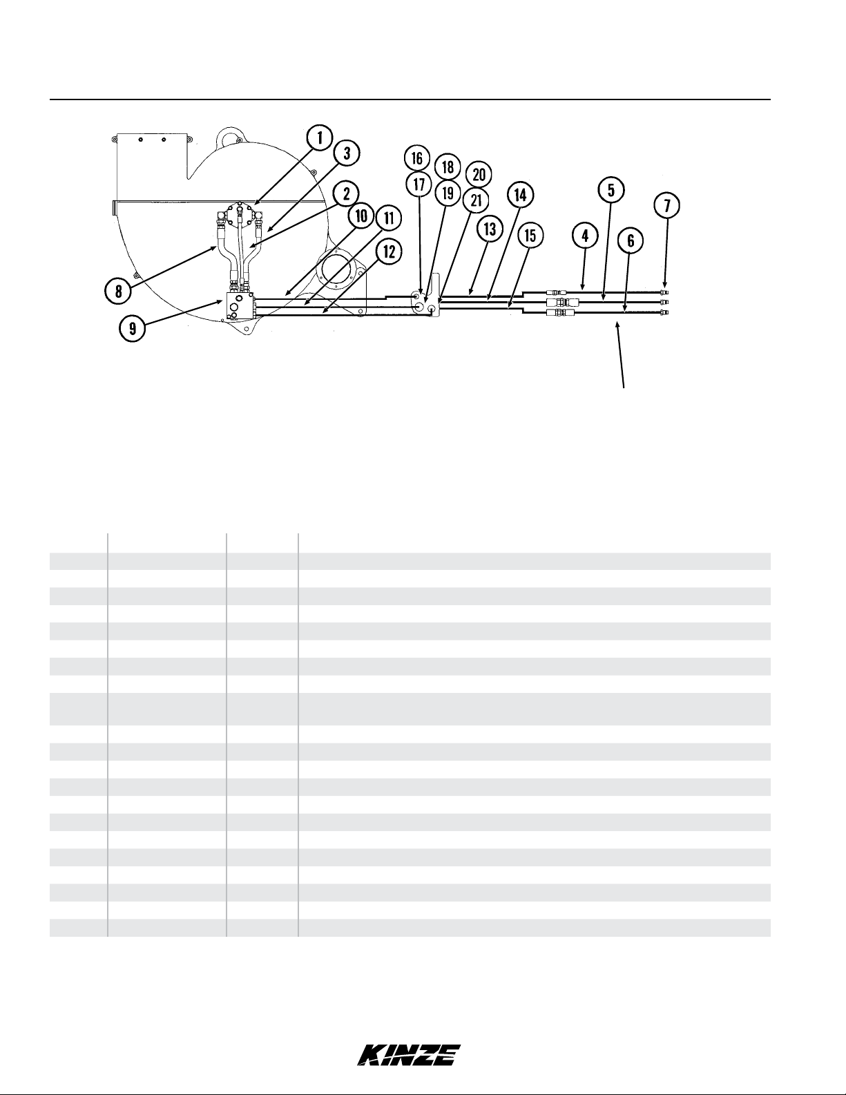
Vacuum Fan Hydraulic Components
M0242Model 3600
See “PTO Pump Drive And
Oil Cooler Option” (located in
M0236-02) if equipped with that
option.
ITEM PART NO. QTY. DESCRIPTION
1 --- - See “Vacuum Fan Hydraulic Motor Assembly” (Located in M0236-02)
2 *A12015 1 Hose Assembly, " x 17"
3 *A8261 1 Hose Assembly, ½" x 13½"
4 *A12019 - Hose Assembly, " x 322", 12 Row 30" “T” Hitch
5 *A3361 - Hose Assembly, ¾" x 322", 12 Row 30" “T” Hitch
6 *A8269 - Hose Assembly, ½" x 322", 12 Row 30" “T” Hitch
7 GD4086 3 ISO Coupler
8 *A3352 1 Hose Assembly, ¾" x 13½"
9 --- - See “Vacuum Fan Motor Valve Block Assembly (Located Below Vacuum Fan Motor
Assembly)” (Located in M0236-02)
10 *A12017 1 Hose Assembly, " x 120"
11 *A3354 1 Hose Assembly, ¾" x 120"
12 *A1467 1 Hose Assembly, ½" x 120"
13 *A12036 - Hose Assembly, " x 104", 12 Row 30"
14 *A3377 - Hose Assembly, ¾" x 104", 12 Row 30"
15 *A8284 - Hose Assembly, ½" x 104", 12 Row 30"
16 G306-06 1 Lock Nut, "-18
17 G2700-06-06 1 Bulkhead Tube Union, "-18 Male JIC
18 G306-12 1 Lock Nut, 1"-12
19 G2700-12 1 Bulkhead Tube Union, 1"-12 Male JIC
20 G306-10 1 Lock Nut, "-14
21 G2700-10 1 Bulkhead Tube Union, "-14 Male JIC
* Hydraulic hose is not stocked by Kinze Repair Parts, but can be made available on a special order basis. Call for quote.
P1 7/11
TM

This page left blank intentionally.
PHA038/PHA025(TWL1f/WGN47a/B0292/TWL1j)
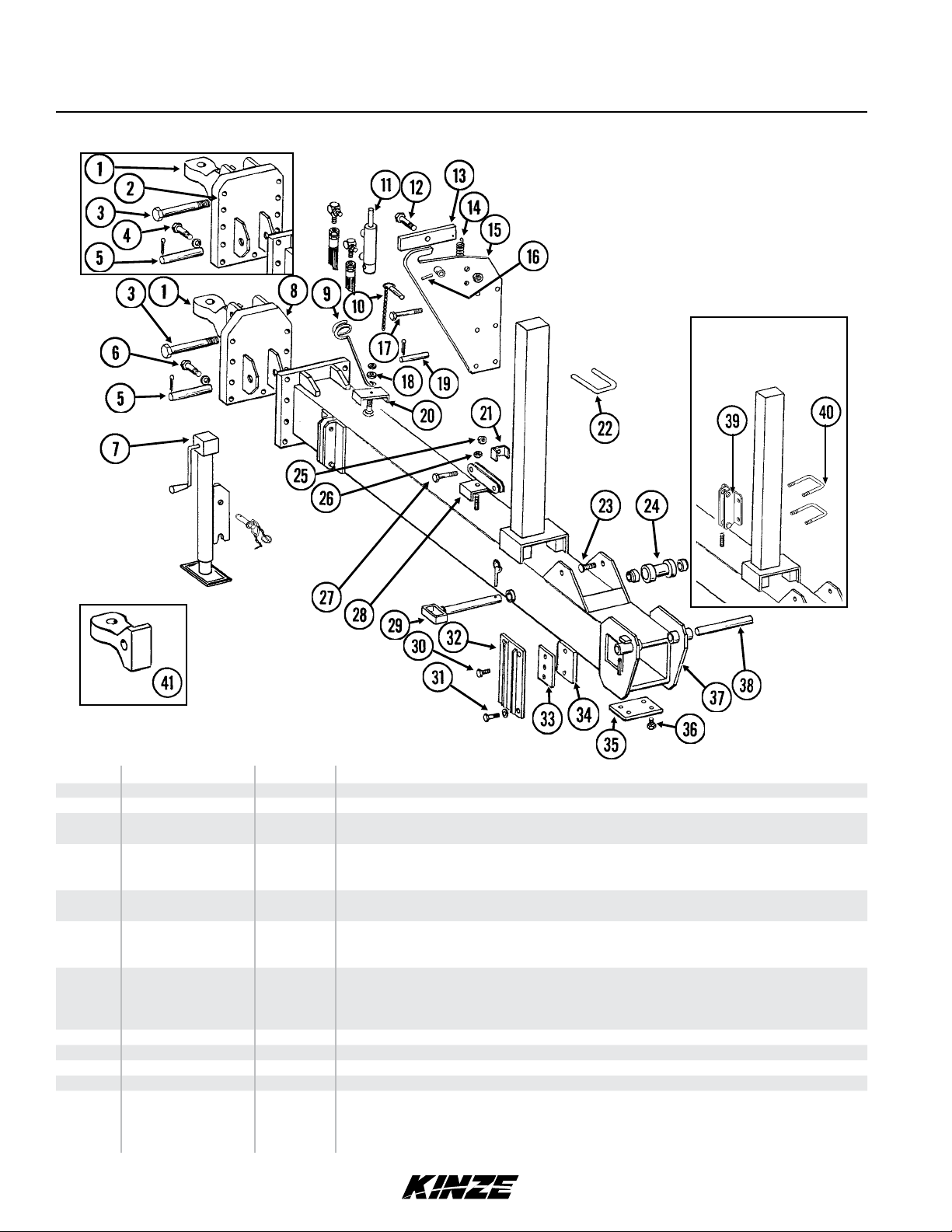
Outer Hitch
M0242Model 3600
Planters Equipped
With PTO Pump And
Oil Cooler Option
ITEM PART NO. QTY. DESCRIPTION
1 GB0237 1 Clevis, Single (1¾" Hole)
2 GA9837 - Hitch Mount, 16 Row 30"
3 G10169
G10157
4 G10802
G10231
G10105
5 GD5173
G10462
6 G10009
G10230
G10104
7 GA13986
GA4995
GR0516
GR0515
8 GA9836 1 Hitch Mount, 12 Row 30" And 12 Row 36"/38" (“Y” Hitch Only)
9 GD8260 1 Hose Holder
10 GA7022 1 Detent Pin W/Chain (Transport Latch Locking Pin)
11 --- See “Transport Latch Cylinder” (Located in M0236-02)
12 G10006
GB0218
GD7805
G10107
P3 7/11
11
11
11
1
1
1
2
9
9
9
1
1
1
1
1
Hex Head Cap Screw, 1¼"-7 x 6"
Lock Nut, 1 ¼"-7
Hex Head Cap Screw, ¾"-10 x 2¾"
Lock Washer, ¾"
Hex Nut, ¾"-10
Pin, 1¼" x 5"
Cotter Pin, " x 2"
Hex Head Cap Screw, "-11 x 2½"
Lock Washer, "
Hex Nut, "-11
Jack Assembly Complete
-
Detent Pin Assembly
-
Crank Assembly
-
Bevel Gear Set, Includes: (2) Bevel Gears, (1) Gear Pin, (1) Groove Pin
Hex Head Cap Screw, "-11 x 2¼"
Bushing, " I.D. x " O.D. x " Long
Special Washer, ", Hardened
Lock Nut, "-11
TM
Outer Hitch
ITEM PART NO. QTY. DESCRIPTION
13 GA7016 1 Catch Bar
14 GD5857 1 Spring
15 GA7433 1 Transport Latch
16 G10765 - Spring Pin, ¼" x 1"
17 G10062
GD2971-09
G10108
18 G11389
G10111
19 GD7137
G10457
20 GD8188
GD8189
21 GD5875 2 Hose Clamp, " x 2½" x 2"
22 GD9953
G11391
G10230
G10104
23 --- 24 GA4418
GA4842
GD6556
25 G10108 1 Lock Nut, "-16
26 G10111 1 Lock Nut, ½"-13
27 G10026
G10112
28 GA5842
GD8189
29 GA13768
GA4845
GD2558
GD2557
30 G10016
G11389
31 G10017
G10016
G10071
32 GA7029
GA7084
GA7085
GA7083
33 GD5154
GD3501
34 GD9959
GD9960
35 GD7519
GD7518
36 G10014
G10228
G11389
37 A7061
A7044
A7073
38 GD7251
GD5804
G10468
39 GA11528 1 Bracket
40 GD16642
G10228
G10102
41 GB0292 - Hitch Clevis, Single (2" Hole)
1
1
1
1
1
1
2
-
-
3
1
6
6
1
-
1
1
1
1
-
1
-
-
4
4
8
10
8-10
2
-
-
-
-
-
-
3
1
4
4
4
-
-
1
2
2
4
4
Hex Head Cap Screw, "-16 x 3"
Sleeve, 2" Long
Lock Nut, "-16
Flat Washer, ½" Plated SAE
Lock Nut, ½"-13
Pin, ¾" x 3 "
Cotter Pin, " x 1 ½"
Hose Clamp, " x 3" x 5"
Rubber Strip, "
U-Bolt, 3" x 4" x "-11
Flat Washer, " SAE
Lock Washer, "
Hex Nut, "-11
See “Hose Take-Up” on page 9
Roller W/Bronze Bushings, 12 Row “Y” Hitch
Roller W/Bronze Bushings, 12 Row “T” Hitch And 16 Row “T” Hitch
Bronze Bushing
Hex Head Cap Screw, ¾"-10 x 2"
Lock Nut, ¾"-10
Bracket, Jack Mount
Rubber Strip, "
Safety Pin, 12¾", 12 Row 30", 12 Row 36"/38" (“Y” Hitch Only)
Safety Pin, 14¾", 16 Row 30"
Lynch Pin, ¼"
Lynch Pin, "
Hex Head Cap Screw, ½"-13 x 2"
Flat Washer, ½" Plated SAE
Hex Head Cap Screw, ½"-13 x 1½", 12 Row
Hex Head Cap Screw, ½"-13 x 2", 16 Row
Serrated Flange Nut, ½"-13
Wear Mount, 12 Row 30", 12 Row 36"/38" (“Y” Hitch Only)
Wear Mount, L.H., 16 Row 30"
Wear Mount, R.H., 16 Row 30"
Wear Pad Retainer, 16 Row 30"
Shim, 4" x 4" (As Required), All Sizes
Shim, 4" x 6" (As Required), 16 Row 30"
Wear Pad, Nylatron, 4" x 4" (As Required), All Sizes
Wear Pad, Nylatron, 4" x 6" (As Required), 16 Row 30"
Shim, 16 Gauge (16 Row Only)
Shim, " (16 Row Only)
Hex Head Cap Screw, ½"-13 x 1"
Lock Washer, ½"
Flat Washer, ½" Plated SAE
Outer Hitch, “T”, 121", 12 Row 30" (Non-Stock Item)
Outer Hitch, “Y”, 121", 12 Row 36"/38" (Non-Stock Item)
Outer Hitch, “T”, 151½", 16 Row 30" (Non-Stock Item)
Pin, 1¼" x 14", 12 Row “T” Hitch And 16 Row “T” Hitch
Pin, 1¼" x 12", 12 Row “Y” Hitch
Pin, " x 2"
U-Bolt, 3" x 4" x ½"-13
Lock Washer, ½"
Hex Nut, ½"-13
Model 3600M0242
7/11 P4
TM
(TWL2i)
Inner Hitch, “Y”
M0242Model 3600
Rev. 8/12
P5
TM
Inner Hitch, “Y”
ITEM PART NO. QTY. DESCRIPTION
1 G10014
G10228
2 GD9959
GD5154
3 G10894 - External Washer
4 GD3537-17 1 Shaft, 1¼" x 6", 12 Row 36"/38"
5 GA7423
G10641
6 GD5804
G10468
7 GD8188
GD8189
8 --- 9 G11169
G10111
10 G10004
G10229
G10101
11 GD10650 1 Hose Clamp
12 G10003
G11387
G10108
13 GD10664 1 Shield (If Applicable)
14 GD5173
G10462
15 G10131 1 Square Head Set Screw, "-18 x ¾"
16 GB0246 1 Shoe
17 GD3537-11 1 Shaft, 1¼" x 7", 12 Row
18 A7428 - Inner Hitch, 191", 12 Row 36"/38" (Non-Stock Item)
19 --- -
20 --- - See “Tongue Lock Cylinder” (Located in M0236-02)
21 GD10530
G10229
G11091
22 G10585
G11389
G10071
23 GD10538-01 1 Sleeve
24 GD13543
GD13544
GD13545
GD13546
25 GD18116 1 Shield (If Applicable)
26 GD5875
G10108
27 GD8189
GD8188
G10111
28 G6400-06-08
GR1037
4
4
2
4-6
1
1
2
-
-
1
1
1
1
1
1
1
1
1
1
1
2
2
1
1
1
1
1
1
1
1
1
1
1
1
2
-
Hex Head Cap Screw, ½"-13 x 1", 12 Row 36"/38"
Lock Washer, ½", 16 Row 30"
Wear Pad, Nylatron, 4" x 4"
Shim, 4" x 4"
Tongue Hook W/Grease Fittings, 12 Row
Grease Fitting, " NPT
Pin, 1¼" x 12", 12 Row
Cotter Pin, " x 2"
Hose Clamp, " x 3" x 5"
Rubber Strip, "
See “Hose Take-Up” on page 9
Hex Head Cap Screw, ½"-13 x 3½"
Lock Nut, ½"-13
Hex Head Cap Screw, "-16 x 1¼"
Lock Washer, "
Hex Nut, "-16
Hex Head Cap Screw, "-16 x 1½"
Flat Washer, " SAE
Lock Nut, "-16
Pin, 1¼" x 5"
Cotter Pin, " x 2"
See “Tongue Cylinder, 12 Row 30” with “T” Hitch and 12 Row 36”/38” with “Y” Hitch”
on page 26
U-Bolt, 2" x 1" x "-16
Lock Washer, "
Serrated Flange Nut, "-16
Hex Head Cap Screw, ½"-13 x 3¼"
Flat Washer, ½" Plated SAE
Serrated Flange Nut, ½"-13
Shim, 2½" x 10", 7 Gauge
Shim, 2½" x 10", 10 Gauge
Shim, 2½" x 10", 12 Gauge
Shim, 2½" x 10", 14 Gauge
Hose Clamp, " x 2½" x 2"
Lock Nut, "-16
Rubber Strip, "
Hose Clamp, " x 3" x 5"
Lock Nut, ½"-13
Connector W/O-Ring, ⁄"-18 Male JIC To ¾"-16 O-Ring
O-Ring
Model 3600M0242
Rev. 8/12 P6
TM
PHA035/PHA036(TWL3f)
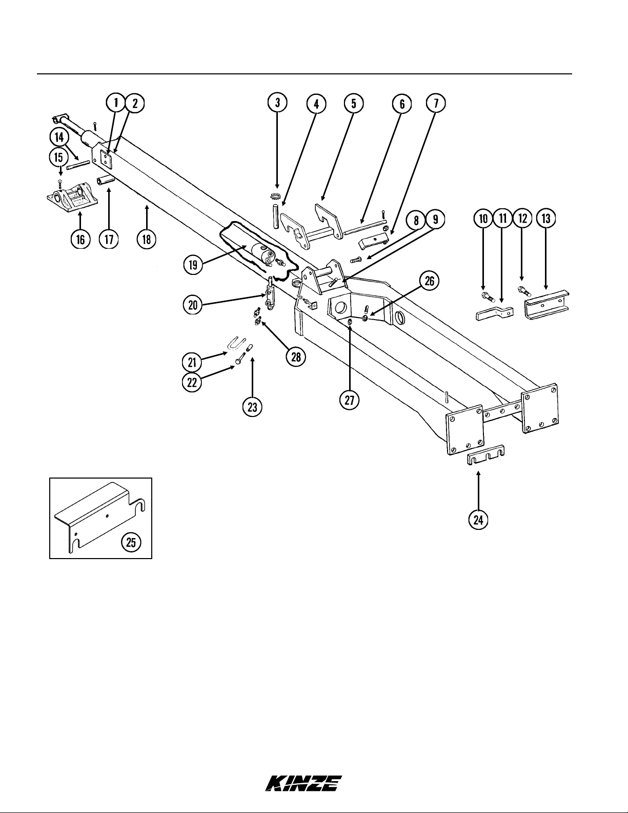
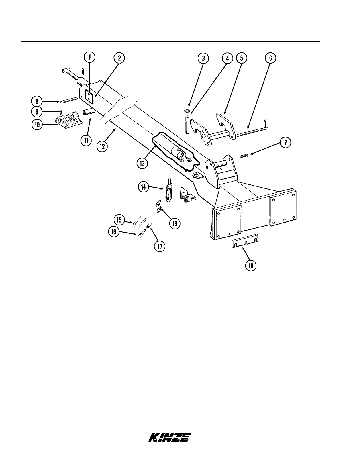
Inner Hitch, “T”
M0242Model 3600
P7 7/11
TM
Inner Hitch, “T”
ITEM PART NO. QTY. DESCRIPTION
1 G10014
G10017
G10228
2 GD9959
GD5154
3 G10894 - External Washer
4 GD3537-17
GD3537-18
5 GA7423
GD7883
G10641
6 GD5804
G10468
7 --- 8 GD5173
G10462
9 G10131 1 Square Head Set Screw, /"-18 x ¾"
10 GB0246 1 Shoe
11 GD3537-11
GD3537-12
12 A7432 - Inner Hitch, 145", 12 Row 30" (Shown) (Non-Stock Item)
13 --- -
14 --- - See “Tongue Lock Cylinder” (Located in M0236-02)
15 GD10530
G11091
G10101
16 G10585
G11389
G10071
17 GD10538-01 1 Sleeve
18 GD13543
GD13544
GD13545
19 G6400-06-08
GR1037
4
4
4
2
4-6
1
-
1
-
-
1
2
1
1
1 Shaft, 1¼" x 7", 12 Row 30"
1
2
2
1
1
1
1
1
1
2
-
Hex Head Cap Screw, ½"-13 x 1", 12 Row 30"
Hex Head Cap Screw, ½"-13 x 1½", 12 Row 36"/38" And 16 Row 30"
Lock Washer, ½", 12 Row 36"/38" And 16 Row 30"
Wear Pad, Nylatron, 4" x 4"
Shim, 4" x 4"
Shaft, 1¼" x 6", 12 Row 30"
Shaft, 1¼" x 7", 12 Row 36"/38" And 16 Row 30"
Tongue Hook W/Grease Fittings, 12 Row 30"
Pin, 1¼" x 14½", 12 Row 36"/38" And 16 Row 30"
Grease Fitting, " NPT
Pin, 1¼" x 12", 12 Row 30"
Cotter Pin, " x 2"
See “Hose Take-Up” on page 9
Pin, 1¼" x 5"
Cotter Pin, /" x 2"
Shaft, 1¼" x 8", 12 Row 36"/38" And 16 Row 30"
See “Tongue Cylinder, 12 Row 30” with “T” Hitch and 12 Row 36”/38” with “Y” Hitch”
on page 26
See “Tongue Cylinder, 16 Row 30” with “T” Hitch” on page 27
U-Bolt, 2" x 1" x "-16
Serrated Nut, "
Hex Nut, "-16
Hex Head Cap Screw, ½"-13 x 3¼"
Flat Washer, ½" Plated SAE
Serrated Flange Nut, ½"-13
Shim, 2½" x 10", 7 Gauge
Shim, 2½" x 10", 10 Gauge
Shim, 2½" x 10", 12 Gauge
Connector W/O-Ring, ⁄”-18 Male JIC To ¾”-16 O-Ring
O-Ring
Model 3600M0242
Rev. 8/12 P8
TM
(TWL137TWL137f)
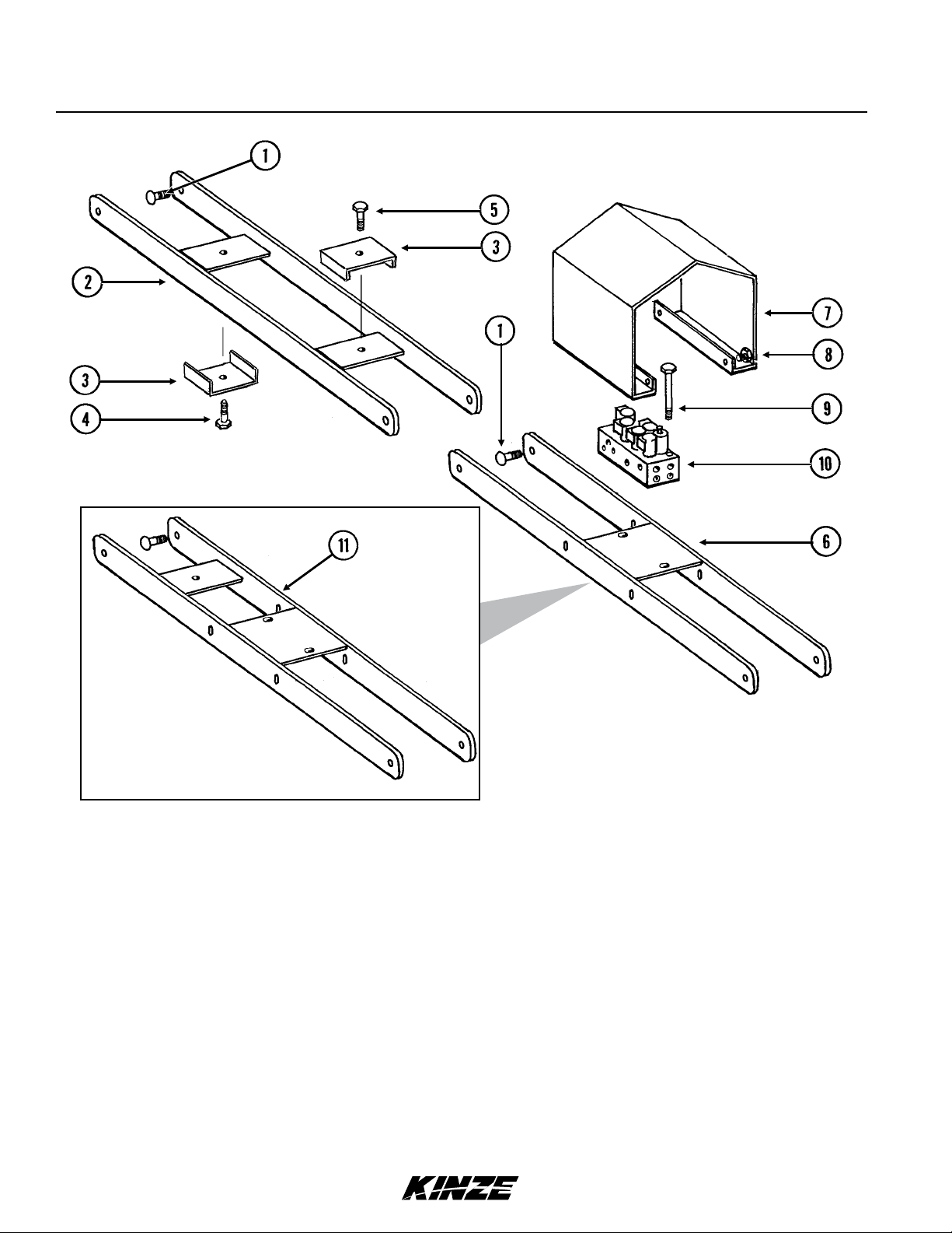
Hose Take-Up
M0242Model 3600
P9 7/11
TM
 Loading...