

Kinze 3200 User Manual

OPERATOR’S MANUAL
M0241-01
MODEL 3200 WING FOLD PLANTER
Rev. 7/14

MODEL 3200
WING FOLD PLANTER
OPERATOR’S MANUAL
M0241-01 Rev. 7/14
This manual is applicable to: Model: 3200 Wing Fold Planters
Serial Number: 680671 to 2014 Production (EdgeVac)
680370 to 2014 Production (Mechanical)
Record the model number and serial number of your planter along with date purchased:
Model Number __________________________________
Serial Number ___________________________________
Date Purchased __________________________________
Monitor Serial Number _______________________________________________
Measured Pulses Per Mile/Km (Radar Distance Sensor) ____________________
Measured Pulses Per Mile/ Km (Magnetic Distance Sensor) _________________
3200
SERIAL NUMBER
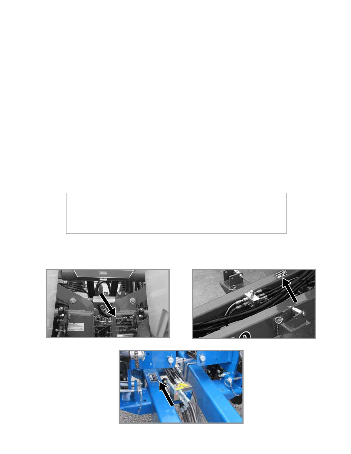
The serial number plate is located on the planter frame as shown below. The serial number provides important information
about your planter and is needed to obtain correct replacement parts. Always provide model number and serial number
to your Kinze Dealer when ordering parts or when contacting Kinze Manufacturing, Inc.
Prior to 2009 production 2009 production and later
2013 production and later
Kinze®, the Kinze® logo, Econo-Fold®,Twin-Line®, Interplant® and EdgeVac® are registered trademarks of Kinze Manufacturing, Inc.
WARRANTY
The Kinze Limited Warranty for your new machine is stated on the retail purchaser’s copy of the Warranty And Delivery
Receipt form. Additional copies of the Limited Warranty can be obtained through your Kinze Dealer.
Warranty, within the warranty period, is provided as part of Kinze’s support program for registered Kinze products which
have been operated and maintained as described in this manual. Evidence of equipment abuse or modification beyond
original factory specifications will void the warranty. Normal maintenance, service and repair is not covered by Kinze
warranty.
To register your Kinze product for warranty, a Warranty And Delivery Receipt form must be completed by the Kinze
Dealer and signed by the retail purchaser, with copies to the Dealer, and to the retail purchaser. Registration must be
completed and submitted to Kinze Manufacturing, Inc. within 5 business days of delivery of the Kinze product to the retail
purchaser. Kinze Manufacturing, Inc. reserves the right to refuse warranty on serial numbered products which have not
been properly registered.
If service or replacement of failed parts which are covered by the Limited Warranty are required, it is the user’s responsibility
to deliver the machine along with the retail purchaser’s copy of the Warranty And Delivery Receipt to the Kinze Dealer
for service. Kinze warranty does not include cost of travel time, mileage, hauling or labor. Any prior arrangement made
between the Dealer and the retail purchaser in which the Dealer agrees to absorb all or part of this expense should be
considered a courtesy to the retail purchaser.
Kinze warranty does not include cost of travel time, mileage, hauling, or labor.
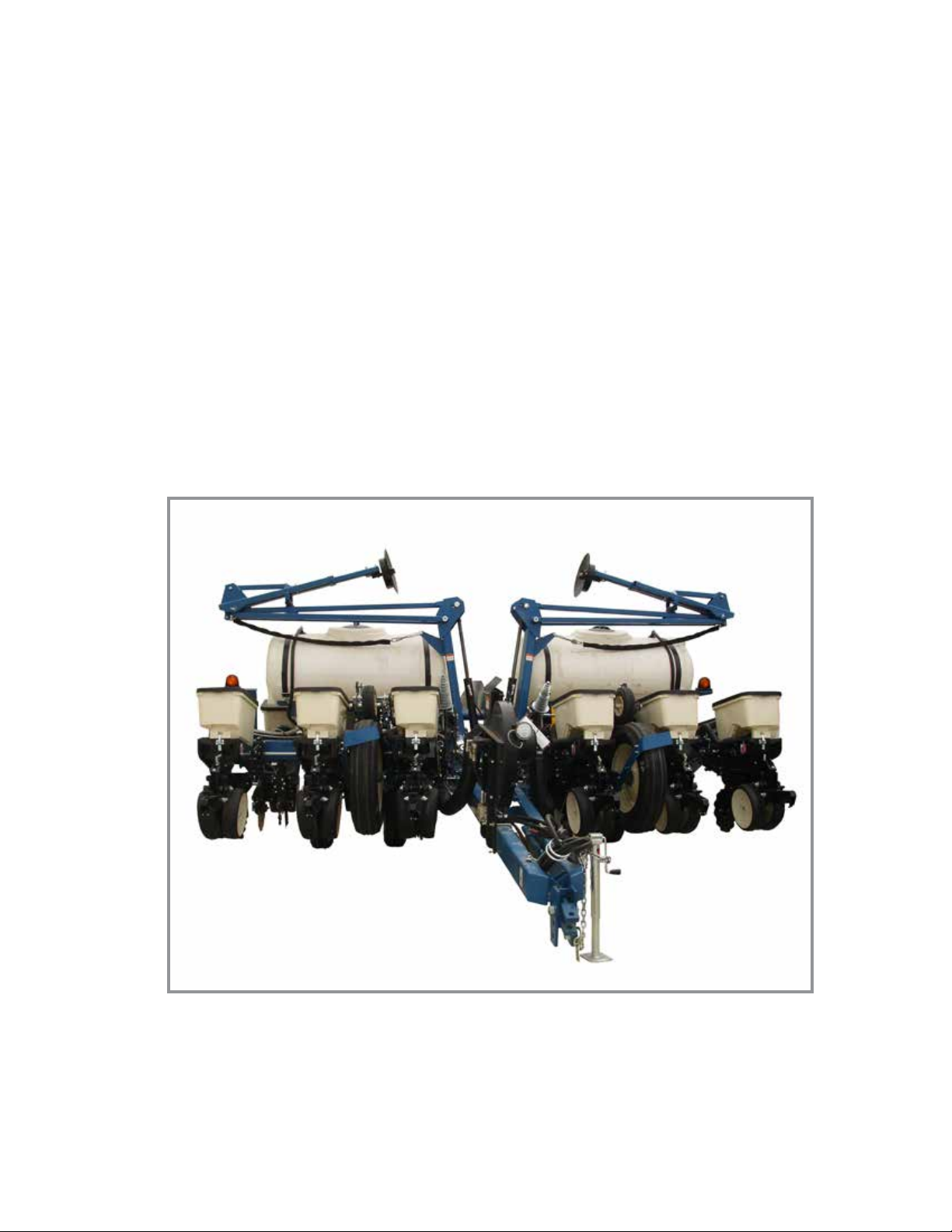
3200 Wing Fold EdgeVac 12 row 30" with liquid fertilizer option (shown folded)

Predelivery/Delivery Checklist
Model 3200M0241-01
TO THE DEALER
Predelivery service includes assembly, lubrication, adjustment and test. This service helps to ensure planter is delivered
to retail customer/end user ready for field use.
PREDELIVERY CHECKLIST
After the planter is completely assembled, use the following checklist and inspect the planter. Check off each item as it
is found satisfactory or after proper adjustment is made.
Row units properly spaced and optional attachments correctly assembled.
All grease fittings in place and lubricated.
All working parts are moving freely. Bolts are tight and cotter pins are spread.
All drive chains properly tensioned and aligned.
Check for oil leaks and proper hydraulic operation.
Hydraulic hoses are routed correctly to prevent damage to hoses.
Inflate tires to specified air pressure. Tighten wheel lug bolts to specified torque.
All safety decals correctly located and legible as shown in Parts Manual. Replace if damaged.
All reflective decals and SMV sign located as shown in Parts Manual and visible when planter is in transport position.
Safety/warning lights correctly installed and working properly.
Paint all parts scratched in shipment or assembly.
All safety lockup devices are on planter and correctly located.
EdgeVac vacuum fan, analog gauge, and digital gauge correctly installed. All hoses and manifolds connected.
Seed meters performance checked on test stand.
Auxiliary safety chain is properly installed and hardware is torqued to specification.
Planter has been thoroughly checked and to the best of my knowledge is ready for delivery to the customer.
(Signature Of Set-Up Person/Dealer Name/Date)
OWNER REGISTER
Name Delivery Date
Street Address Model No. 3200 Serial No.
City, State/Province Dealer Name
ZIP/Postal Code Dealer No.
6/11
TM

Predelivery/Delivery Checklist
M0241-01Model 3200
DELIVERY CHECKLIST
Use the following checklist at time planter is delivered as a reminder of very important information which should be
conveyed to retail customer/end user. Check off each item as it is fully explained.
Check for proper operation of vacuum fan (If Applicable) with tractor to be used with planter.
Life expectancy of this or any other machine is dependent on regular lubrication as directed in the Operator Manual.
All applicable safety precautions.
Along with retail customer/end user, check reflective decals and SMV sign are clearly visible with planter in transport
position and attached to tractor. Check safety/warning lights are in working condition. Tell retail customer/end user
to check federal, state/provincial, and local regulations before towing or transporting on a road or highway.
Give Operator Manual, Parts Manual, and all Instruction Sheets to retail customer/end user and explain all operating
adjustments.
Read warranty to retail customer/end user.
Complete Warranty and Delivery Report form.
To the best of my knowledge this machine has been delivered ready for field use and customer has been fully
informed as to proper care and operation.
(Signature Of Delivery Person/Dealer Name/Date)
AFTER DELIVERY CHECKLIST
The following is a list of items we suggest to check during the first season of use of the equipment.
Check planter performance with retail customer/end user.
Check performance of EdgeVac or mechanical seed metering system with retail customer/end user.
Review importance of proper maintenance and adherence to all safety precautions with retail customer/end user.
Check for parts that may need to be adjusted or replaced.
Check all safety decals, reflective decals, and SMV sign are correctly located as shown in the Parts Manual and that
decals are legible. Replace if damaged or missing.
Check safety/warning lights are working properly.
(Signature Of Follow-Up Person/Dealer Name/Date)
All registrations must be submitted online at “business.kinze.com” within 5 business days of delivery.
Retain a copy of this form for auditing purposes.
Tear Along Perforation
Rev. 6/14
TM

Table of Contents
Model 3200M0241-01
OVERVIEW
To the Owner . . . . . . . . . . . . . . . . . . . . . . . . . . . . . . . . . . . 1-1
General Information . . . . . . . . . . . . . . . . . . . . . . . . . . . . . . 1-2
Specifications ..................................1-2
Tractor Hydraulic Requirements. . . . . . . . . . . . . . . . . . . . . 1-2
General Safety Rules. . . . . . . . . . . . . . . . . . . . . . . . . . . . . 1-3
Safety Signs and Decals ..........................1-4
Safety Precautions. . . . . . . . . . . . . . . . . . . . . . . . . . . . . . . 1-4
MACHINE OPERATION
Lift Cylinder Lockups .............................2-1
Wing Safety Pins ................................2-1
Hydraulic Operation . . . . . . . . . . . . . . . . . . . . . . . . . . . . . . 2-2
Initial Preparation ................................2-4
Tractor Requirements. . . . . . . . . . . . . . . . . . . . . . . . . . . . . 2-4
Tractor Preparation and Hookup ....................2-5
Level Planter ...................................2-6
Manual Wing Fold Transport to Field Operation. . . . . . . . . 2-7
Manual Wing Fold Field Operation to Transport. . . . . . . . . 2-8
Hydraulic Wing Fold Transport to Field Operation. . . . . . . 2-9
Hydraulic Wing Fold Field Operation to Transport ......2-11
Hydraulic Row Marker Operation ...................2-12
Row Marker Speed Adjustment . . . . . . . . . . . . . . . . . . . . 2-13
Row Marker Adjustment. . . . . . . . . . . . . . . . . . . . . . . . . . 2-14
Transporting Planter. . . . . . . . . . . . . . . . . . . . . . . . . . . . . 2-15
Contact Drive Spring Adjustment ...................2-15
Wrap Spring Wrench ............................2-16
Contact Wheel Drive Sprockets . . . . . . . . . . . . . . . . . . . .2-16
Seed Rate Transmission Adjustment. . . . . . . . . . . . . . . . 2-17
Standard and Half Rate (2 to 1) Drives ..............2-17
Shear Protection ...............................2-18
Tire Scraper ...................................2-18
Ridge Planting . . . . . . . . . . . . . . . . . . . . . . . . . . . . . . . . . 2-18
Digital Vacuum Gauge Operation. . . . . . . . . . . . . . . . . . . 2-19
Analog Vacuum Gauge ..........................2-19
Ag Leader Integra Display . . . . . . . . . . . . . . . . . . . . . . . .2-20
Planter Monitor Module (PMM) ....................2-20
Kinze ISOBUS Option ...........................2-20
Ag Leader Electric Clutches ......................2-20
Point Row Clutches . . . . . . . . . . . . . . . . . . . . . . . . . . . . . 2-21
Two-Speed Point Row Clutches. . . . . . . . . . . . . . . . . . . . 2-22
Field Test .....................................2-23
Check Seed Population ..........................2-23
Determining Pounds Per Acre (Brush-Type Meter) .....2-24
Determining Bushels Per Acre. . . . . . . . . . . . . . . . . . . . . 2-24
Granular Chemical Application Field Check ..........2-25
ROW UNIT OPERATION
Planting Depth . . . . . . . . . . . . . . . . . . . . . . . . . . . . . . . . . .3-1
“V” Closing Wheel Adjustment (Rubber or Cast Iron) ....3-1
Closing Wheel Shield (Rubber or Cast Iron “V”
Closing Wheels) ..............................3-2
Drag Closing Attachment. . . . . . . . . . . . . . . . . . . . . . . . . . 3-2
Covering Discs/Single Press Wheel Adjustment ........3-3
Seed Hoppers ..................................3-4
Seed Meter Drive Release. . . . . . . . . . . . . . . . . . . . . . . . . 3-4
Row Unit Extension Brackets. . . . . . . . . . . . . . . . . . . . . . . 3-4
Row Unit Chain Routing. . . . . . . . . . . . . . . . . . . . . . . . . . . 3-5
Quick Adjustable Down Force Springs Option (Standard
or Heavy Duty) ...............................3-6
Brush-Type Seed Meter . . . . . . . . . . . . . . . . . . . . . . . . . . . 3-8
Finger Pickup Seed Meter . . . . . . . . . . . . . . . . . . . . . . . . .3-9
EdgeVac Seed Meters ...........................3-10
Seed Meter Cleanout. . . . . . . . . . . . . . . . . . . . . . . . . . . . 3-13
Additives .....................................3-14
Frame Mounted Coulter (Pull Row Only). . . . . . . . . . . . . 3-15
Residue Wheels (for Frame Mounted Coulter). . . . . . . . . 3-15
Row Unit Mounted Disc Furrower (Pull Row Only) .....3-16
Row Unit Mounted Bed Leveler (Pull Row Only) .......3-16
Row Unit Mounted Residue Wheel .................3-17
Row Unit Mounted No Till Coulter ..................3-18
Coulter Mounted Residue Wheels . . . . . . . . . . . . . . . . . . 3-18
Granular Chemical Hopper and Drive ...............3-19
Spring Tooth Incorporator ........................3-19
Granular Chemical Banding Options . . . . . . . . . . . . . . . .3-20
Granular Chemical Bander Shield . . . . . . . . . . . . . . . . . .3-20
FERTILIZER
Double Disc Fertilizer Opener ......................4-1
Notched Single Disc Openers (Style A & B) ...........4-2
Residue Wheel Attachment for Notched Single
Disc Fertilizer Opener ..........................4-3
Depth/Gauge Wheel Attachment for Notched Single
Disc Fertilizer Opener ..........................4-3
HD Single Disc Fertilizer Opener ....................4-4
Liquid Fertilizer Attachment ........................4-6
RATE CHARTS . . . . . . . . . . . . . . . . . . . . . . . . . . . . 5-1
MONITOR OPERATION
KPM I Electronic Seed Monitor .....................6-1
KPM II Stack-Mode Electronic Seed Monitor. . . . . . . . . . . 6-6
KPM III Electronic Seed MonItor Ver. 3.1. . . . . . . . . . . . . 6-24
Lubrication . . . . . . . . . . . . . . . . . . . . . . . . . . . . . . . . . . . . .7-1
Lubrication Symbols .............................7-1
Rev. 7/14 i
TM

Table of Contents
M0241-01Model 3200
Sealed Bearings ................................7-1
Wrap Spring Wrench Assembly. . . . . . . . . . . . . . . . . . . . . 7-1
Drive Chains ...................................7-2
Bushings ......................................7-3
Grease Fittings .................................7-4
Liquid Fertilizer Piston Pump Crankcase Oil Level ......7-7
Mounting Bolts and Hardware ......................7-8
Tire Pressure . . . . . . . . . . . . . . . . . . . . . . . . . . . . . . . . . . .7-9
Model 3200 Operating Tire Pressure. . . . . . . . . . . . . . . . 7-10
Chain Tension Adjustment . . . . . . . . . . . . . . . . . . . . . . . . 7-10
Finger Pickup Seed Meter Inspection/Adjustment. . . . . . 7-11
Cleaning Finger Pickup Seed Meter For Storage ......7-12
Brush-Type Seed Meter Maintenance ...............7-13
Cleaning Brush-Type Seed Meter For Storage ........7-14
Vacuum Manifold Maintenance ....................7-14
EdgeVac Seed Meter Maintenance . . . . . . . . . . . . . . . . . 7-15
EdgeVac Seed Meter Cleanout ....................7-15
Drag Closing Attachment ........................7-16
Gauge Wheel Adjustment ........................7-16
Gauge Wheel Arm Bushing/Seal Replacement. . . . . . . . 7-17
Gauge Wheel Arm Pivot Spindle Replacement . . . . . . . . 7-17
15" Seed Opener Disc Blade/Bearing Assembly .......7-18
Seed Tube Guard/Inner Scraper ...................7-19
Frame Mounted Coulter .........................7-19
Residue Wheels (For Use With Frame
Mounted Coulter). . . . . . . . . . . . . . . . . . . . . . . . . . . . . 7-20
Row Unit Mounted Disc Furrower ..................7-20
Row Unit Mounted Bed Leveler . . . . . . . . . . . . . . . . . . . . 7-21
Row Unit Mounted Residue Wheel .................7-21
Row Unit Mounted No Till Coulter ..................7-22
Coulter Mounted Residue Wheels . . . . . . . . . . . . . . . . . . 7-22
Granular Chemical Attachment ....................7-23
Spring Tooth Incorporator ........................7-23
Fertilizer Check Valve Cleaning and Repair ...........7-23
Row Marker Sequencing/Flow Control Valve Inspection 7-24
Row Marker Bearing Lubrication or Replacement . . . . . . 7-25
Wheel Bearing Repack or Replacement .............7-26
EdgeVac Check Valve Inspection ..................7-26
EdgeVac Relief Valve Cartridge Inspection ..........7-26
Single and Two-Speed Point Row Clutch Maintenance 7-27
Piston Pump Storage. . . . . . . . . . . . . . . . . . . . . . . . . . . . 7-29
Preparing Planter for Storage .....................7-29
Electrical Wiring Diagram for Light Package ..........7-30
Point Row Clutch Electrical Wiring Diagrams .........7-31
Two-Speed Point Row Clutch Electrical Wiring Diagrams 7-32
Two-Speed Point Row Clutches Electrical
Wiring Diagrams .............................7-33
Hydraulic System Schematic - Planter Raising . . . . . . . . 7-34
Hydraulic System Schematic - Planter Lowering .......7-34
Hydraulic System Schematic - Optional Hydraulic
Wing Fold . . . . . . . . . . . . . . . . . . . . . . . . . . . . . . . . . . 7-35
Hydraulic System Schematic - Vacuum Fan
Motor System ...............................7-35
Electric Clutch Schematic ........................7-36
ISOBUS CAN Jumper Cable . . . . . . . . . . . . . . . . . . . . . .7-36
ISOBUS Clutch Cable ...........................7-37
Signal. . . . . . . . . . . . . . . . . . . . . . . . . . . . . . . . . . . . . . . . 7-37
Clutch Cable ..................................7-37
Row 6/11 .....................................7-37
ISOBUS Implement Cable . . . . . . . . . . . . . . . . . . . . . . . . 7-38
Section Adapter Cable ...........................7-38
Product Control Module Cable. . . . . . . . . . . . . . . . . . . . . 7-39
Implement Switch Extension Cable . . . . . . . . . . . . . . . . .7-40
TROUBLESHOOTING
Closing Wheel Troubleshooting .....................8-1
KPM I/KPM II Stack-Mode Electronic Seed Monitors
Troubleshooting .......................8-1
KPM III Electronic Seed Monitor Troubleshooting . . . . . 8-2
Lift Circuit Operation Troubleshooting ................8-3
Piston Pump Troubleshooting ......................8-4
Point Row Clutch Troubleshooting . . . . . . . . . . . . . . . . . . .8-5
Row Marker Operation Troubleshooting. . . . . . . . . . . . . . . 8-6
Seed Meter (Brush-Type) Troubleshooting. . . . . . . . . . . . .8-7
Seed Meter (Finger Pickup) Troubleshooting . . . . . . . . . . . 8-8
Seed Metering System (EdgeVac) Troubleshooting. . . . . . 8-9
Rev. 7/14
ii
TM

To the Owner
Model 3200M0241-01
Kinze Manufacturing, Inc. would like to thank you for your patronage. We appreciate your confidence in Kinze
farm machinery. Your Kinze planter has been carefully designed to provide dependable operation in return for your
investment.
This manual has been prepared to aid you in the operation and maintenance of the planter. It should be
considered a permanent part of the machine and remain with the machine when you sell it.
It is the responsibility of the user to read and understand the Operator Manual in regards to safety, operation,
lubrication and maintenance before operation of this equipment. It is the user’s responsibility to inspect and service
the machine routinely as directed in the Operator Manual. We have attempted to cover all areas of safety, operation,
lubrication and maintenance; however, there may be times when special care must be taken to fit your conditions.
Throughout this manual the symbol and the words DANGER, WARNING, and CAUTION are used to call
attention to safety information that if not followed, will or could result in death or injury. NOTICE and NOTE are used to
call your attention to important information. The definition of each of these terms follows:
DANGER Indicates a hazardous situation which, if not avoided, will result in death or serious
injury.
WARNING Indicates a hazardous situation which, if not avoided, could result in death or serious
injury.
CAUTION, used with the safety alert symbol, indicates a hazardous situation which, if not avoided,
could result in minor or moderate injury.
NOTICE is used to address practices not related to personal injury.
NOTE: Special point of information or machine adjustment instructions.
WARNING
Improperly operating or working on this equipment could result in
death or serious injury. Read and follow all instructions in Operator
Manual before operating or working on this equipment.
WARNING
Some photos in this manual may show safety covers, shields, or
lockup devices removed for visual clarity. NEVER OPERATE OR
WORK ON machine without all safety covers, shields, and lockup
devices in place as required.
NOTE: Photos in this manual may be of prototype machines. Production machines may vary in
appearance.
NOTE: Some photos and illustrations in this manual show optional attachments installed. Contact
your Kinze Dealer for purchase of optional attachments.
6/11 1-1
TM

Overview
M0241-01Model 3200
GENERAL INFORMATION
This manual covers all production years of the Model 3200 planter. Contact your Kinze dealer for additional options
which may be available for your specific model year planter.
Information in this manual was current at time of printing. However, due to Kinze’s ongoing product improvement,
production changes may cause your machine to appear slightly different in detail. Kinze Manufacturing, Inc. reserves
the right to change specifications or design without notice and without incurring obligation to install the same on
machines previously manufactured.
Right hand (R.H.) and left hand (L.H.), as used throughout this manual, are determined by facing in direction machine
travels in use, unless otherwise stated.
SPECIFICATIONS
Specification
Number of Rows 8 Row 36"/38" 12 Row 30"
Weight Empty (Mechanical)* 6,444 lbs (2,923 kg) 7,500 lbs (3,402 kg)
Weight Empty (EdgeVac)* 6,958 lbs (3,156 kg) 8,066 lbs (3,659 kg)
Transport Height 9' 1" (2.77M) 9' 1" (2.77M)
Transport Width 14' 7" (4.45M) 16' 2" (4.93M)
Length 17' 9" (5.41M) 17' 9" (5.41M)
Planting Width 27' 0" (8.23M) 31' 4" (8.23M)
Seed Capacity 1.75 bu. (EdgeVac/Hopper); 1.90 bu. (Mechanical/Hopper)
Transport Tires
Contact Drive Tires
Field Lift
Row Markers
*Base machine weights include planter frame including row markers, hydraulic cylinders, hoses, fittings, tires, wheels,
drive and drill shafts, sprockets, chains and required drive components, parking jack, safety/warning lights, SMV sign,
transport safety chain, and Kinze pull row units (closing wheel arms less closing wheels) with seed hopper, lid, and dual
quick adjustable down force springs option. EdgeVac includes additional weight of fan, manifolds, and hoses.
Six 7.50" x 20" 8 ply rib implement tires w/center groove - Inflate to 40 psi (275.7 kPa)
Two 4.10" x 6" spring-loaded contact drive tires.
Two Master/slave rephasing with two assist cylinders (six cylinders)
Three-fold low profile with 16" solid concave blade, cast iron hubs, and depth bands.
- Inflate to 50 psi (344.7 kPa)
TRACTOR HYDRAULIC REQUIREMENTS
Configuration Requirements Description
Base machine with mechanical meters.
Manual fold.
Base machine with mechanical meters.
Hydraulic fold.
Base machine with EdgeVac meters.*
Manual fold.
Base machine with EdgeVac meters*
Hydraulic fold.
*Seed meter/vacuum system - 13 GPM @ 2000- zero psi case drain plus one SCV (pressure and return) for
vacuum fan hydraulic motor.
2 SCV 15 gpm
2 SCV 15 gpm
3 SCV 30 gpm
3 SCV 30 gpm
#1 SCV: Planter lift
#2 SCV: Markers
#1 SCV: Planter lift
#2 SCV: Markers/fold (manual selector valve)
#1 SCV: Planter lift
#2 SCV: Markers
#3 SCV: EdgeVac fan
#1 SCV: Planter lift
#2 SCV: Markers/fold (manual selector valve)
#3 SCV: EdgeVac fan
1-2 6/11
TM

General Safety Rules
Model 3200M0241-01
1. Read and understand instructions provided in this
manual and warning labels. Review these instructions
frequently!
2. This machine is designed and built with your safety
in mind. Do not make any alterations or changes to this
machine. Any alteration to design or construction may
create safety hazards.
3. A large portion of farm accidents happen from fatigue
or carelessness. Safe and careful operation of tractor and
planter will help prevent accidents.
4.
Never allow planter to be operated by anyone unfamiliar
with operation of all functions of the unit. Operators must
read and thoroughly understand all instructions given in
this manual before operating or working on equipment.
5. Be aware of bystanders, particularly children! Always
look around to make sure it is safe to start tow vehicle
engine or move planter. This is particularly important with
higher noise levels and quiet cabs, as you may not hear
people shouting.
6. Make sure planter weight does not exceed towing
capacity of tractor, or bridge and road limits. This is critical
to maintain safe control and prevent death or injury, or
property and equipment damage.
7. Never ride or allow others to ride on planter.
8. Store planter in an area away from human activity. DO
NOT permit children to play on or around the stored unit.
15. Use of aftermarket hydraulic, electric, or PTO drives
may create serious safety hazards to you and people
nearby. If you install such drives, follow all appropriate
safety standards and practices to protect you and others
near this planter from injury.
16. Follow all federal, state/provincial, and local
regulations when towing farm equipment on a public
highway. Use safety chain (not an elastic or nylon/
plastic tow strap) to retain connection between towing
and towed machines in the event of primary attaching
system separation.
17. Make sure all safety/warning lights, SMV sign, and
reflective decals are in place and working properly
before transporting the machine on public roads.
18. Limit towing speed to 15 MPH. Tow only with farm
tractor of a minimum 90 HP. Allow for unit length when
making turns.
19. Reduce speed prior to turns to avoid the risk of
overturning. Always drive at a safe speed relative to
local conditions and ensure your speed is slow enough
for a safe emergency stop.
20. Chemical application is often an integral part of
planting. Follow label instructions for proper chemical
mixing, handling and container disposal methods.
21. Be familiar with safety procedures for immediate
first aid should you accidentally contact chemical
substances.
9. Keep hands, feet, and clothing away from moving parts.
Do not wear loose-fitting clothing which may catch in
22. Use the proper protective clothing and safety
equipment when handling chemicals.
moving parts.
10. Always wear protective clothing, shoes, gloves,
hearing, and eye protection applicable for the situation.
11. Do not allow anyone to stand between tongue or hitch
and towing vehicle when backing up to planter.
13. Prevent electrocution, other injuries, or property
and equipment damage. Watch for obstructions such as
wires, tree limbs, etc. when operating machine. Be aware
of clearances during turns and when folding/unfolding
planter.
14. Reinstall all guards removed for maintenance
activities. Never leave guards off during operation.
6/11 1-3
23. Chemicals are supplied with Material Safety Data
Sheets (MSDS) that provide full information about the
chemical, its effects on exposure, and first aid needs
in the event of an emergency. Keep your MSDS file
up-to-date and available for first responders in case of
emergency.
24. When servicing ground engaging components such
as opening disks and firming points, use special care to
avoid points and edges worn sharp during use.
25. Use professional help if you are unfamiliar with
working on hydraulic systems. Pressurized hydraulic
fluid can penetrate body tissue and result in death,
serious infection, or other injuries.
TM

Safety Precautions
M0241-01Model 3200
Following are some common hazard warnings associated with this equipment. Pay close attention to all safety,
operating, and maintenance information in this manual and decals applied to your equipment.
DANGER!
Contacting or coming close to power lines or other high energy
sources will cause death or serious injury. Keep away from power
lines or high energy sources at all times.
WARNING
Improperly operating or working on this equipment could result in
death or serious injury. Read and follow all instructions in Operator
Manual before operating or working on this equipment.
WARNING
Falling equipment can cause death or serious injury. Install all lockup
devices or lower planter to ground before working on equipment.
WARNING
Explosive separation of rim and tire parts can cause death or serious
injury.Overination.rimandtireservicing,improperuseofrimsandtires,
or worn or improperly maintained tires could result in a tire explosion.
SAFETY SIGNS AND DECALS
WARNING
Allsafety/warninglights,reectivedecals,andSMVsignmustbe
in place and visible before transporting machine on public roads or
death, serious injury, and damage to property and equipment may
result. Check federal, state/provincial, and local regulations before
transporting equipment on public roads.
Safety signs and decals are placed on the machine to warn of hazards and provide important operating and maintenance
instructions. Information on these signs are for your personal safety and the safety of those around you. FOLLOW ALL
SAFETY INSTRUCTIONS!
• Keepsignscleansotheycanbeeasilyseen.Washwithsoapandwaterorcleaningsolutionasrequired.
• Replacesafetysignsifdamaged,paintedover,ormissing.
• CheckreectivedecalsandSMVsignperiodically.Replaceiftheyshowanylossofofreectiveproperties.
• Whenreplacingdecals,cleanmachinesurfacethoroughlywithsoapandwaterorcleaningsolutionto
remove all dirt and grease.
NOTE: Safety sign and decal locations are shown in the Parts Manual for this machine.
NOTE:StyleandlocationsofSMVsign,reectivedecals,andsafety/warninglightsconformto
ANSI/ASABE S279.14 JUL 2008 and ANSI/ASABE S276.6 JAN 2005.
1-4 6/11
TM
Machine Operation
Model 3200M0241-01
The following information is general in nature and was written to aid the operator in preparation of the tractor and
planter for use, and to provide general operating procedures. The operator’s experience, familiarity with the machine
and the following information should combine for efficient planter operation and good working habits.
NOTICE
Always raise planter out of ground when making sharp turns or
backing up or tractor and equipment may be damaged.
Kinze EdgeVac Seed Metering System includes seed meters, seed discs and an air system consisting of a hydraulic
driven vacuum fan which draws air through the manifolds and hoses and the seed meters on each row unit.
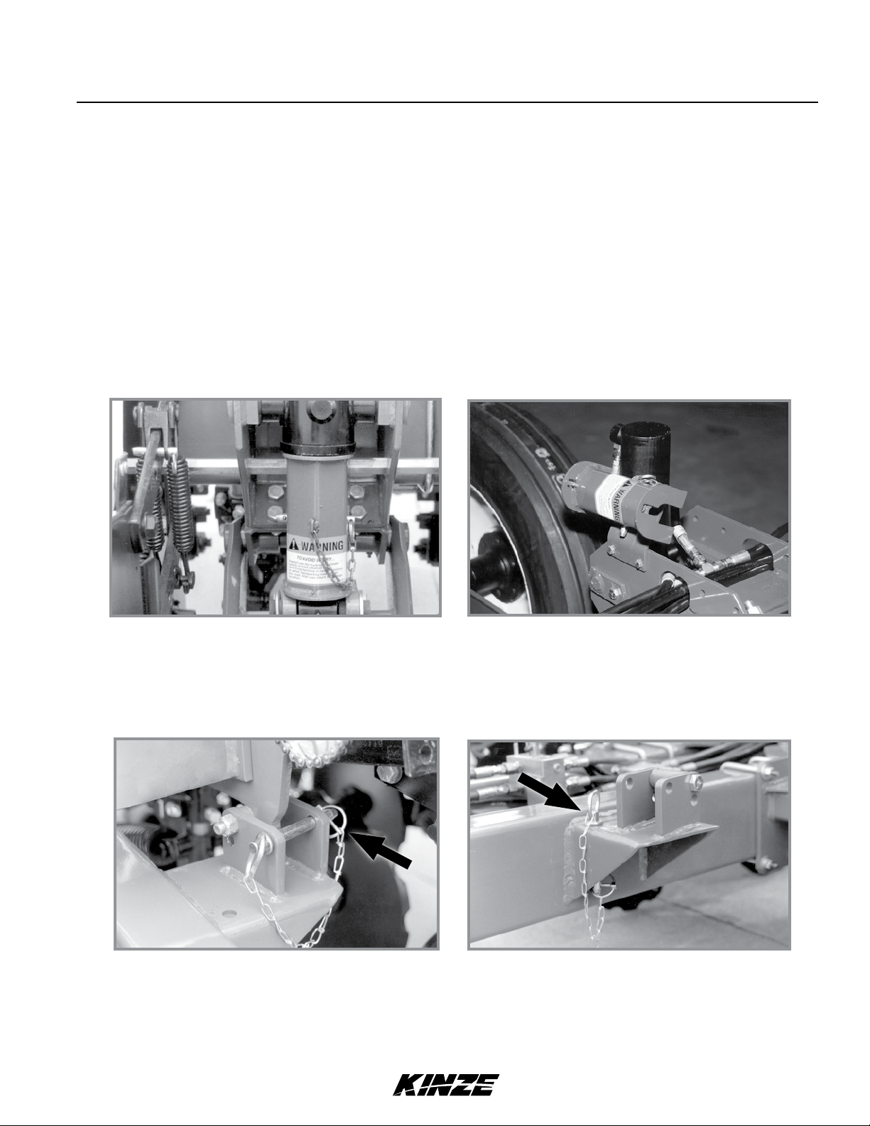
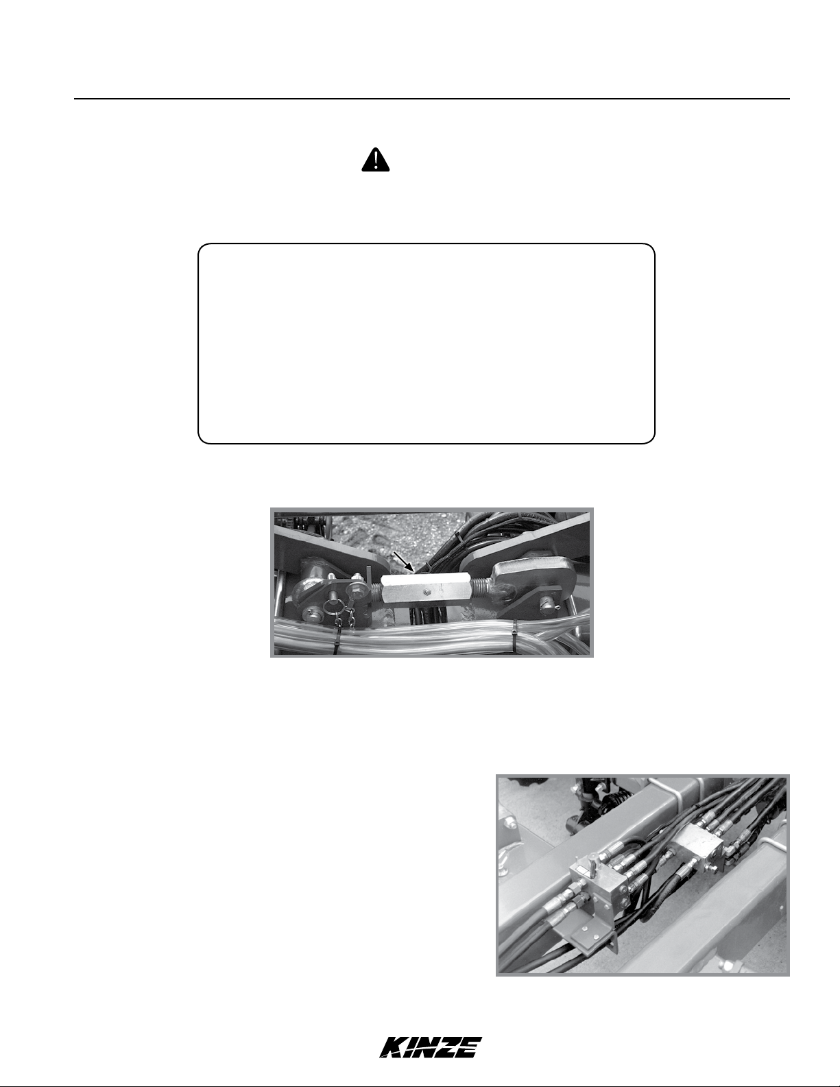
LIFT CYLINDER LOCKUPS
Install all lift cylinder lockups before transporting or working under or around planter.
Lift cylinder lockup in transport position
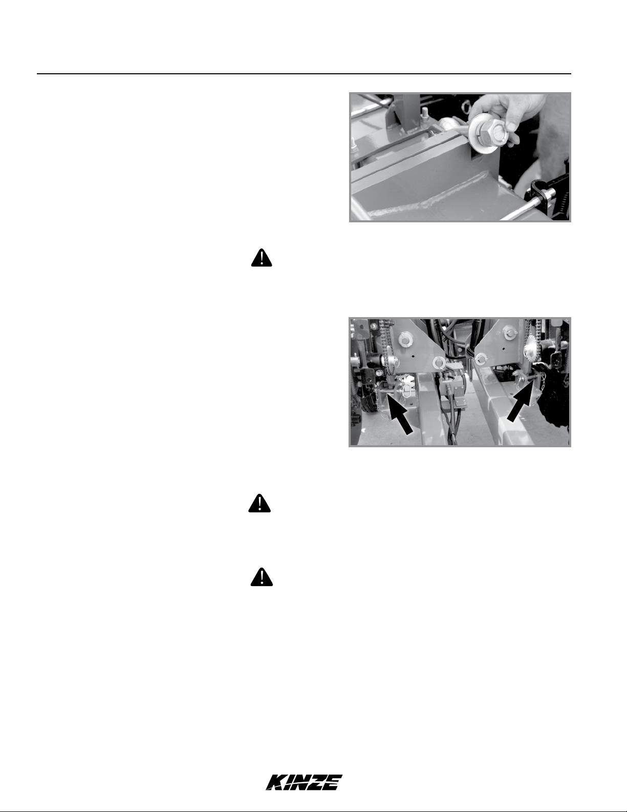
WING SAFETY PINS
Secure wings with safety pins before transporting planter.
Wing safety pin in transport position Wing safety pin in storage position
Lift cylinder lockup in storage position
6/11 2-1
TM
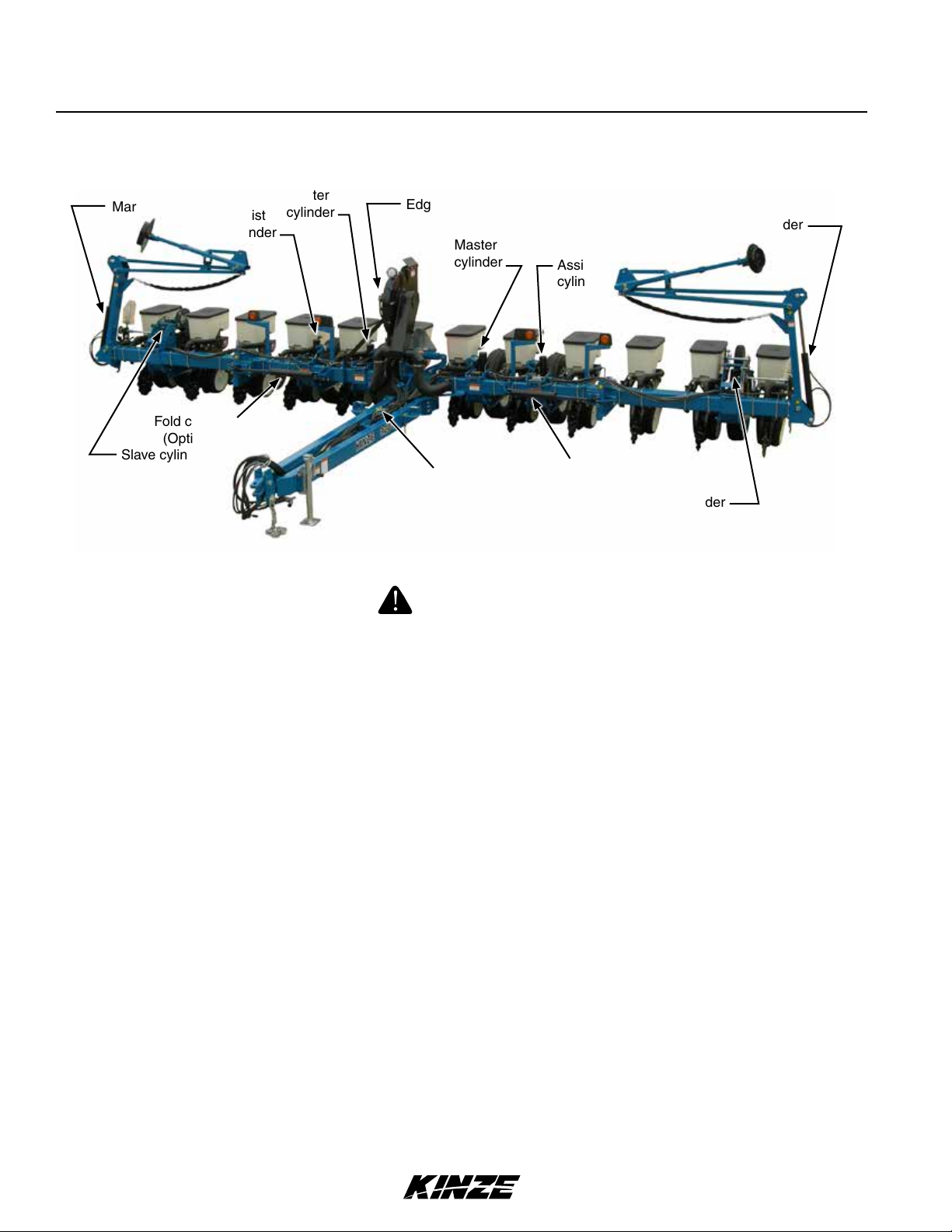
HYDRAULIC OPERATION
Machine Operation
M0241-01Model 3200
Marker cylinder
Fold cylinder
(Optional)
Slave cylinder
Assist
cylinder
Master
cylinder
EdgeVac fan motor and valve block
Master
cylinder
Selector valve
(Optional)
Assist
cylinder
Fold cylinder
(Optional)
Marker cylinder
Slave cylinder
3200 Hydraulic component locations
WARNING
Uncontrolled machine movement can crush or cause loss of control
resulting in death, serious injury, or damage to property and equipment.
Install all safety lockup devices before working under or transporting
this equipment.
PLANTER LIFT SYSTEM
Planter lift system consists of six cylinders with one master, one slave, and one lift assist cylinder on each half of
planter.
With this master/slave hydraulic lift system, oil is forced into base end of master and lift assist cylinders when tractor
hydraulic lever is moved to raise position. As master cylinder is extended, oil from rod end of master cylinder is forced
into base end of slave cylinder.
Displacement on master cylinder rod end is equal to displacement on slave cylinder base end which causes cylinders
to move at same rate so planter raises and lowers evenly.
NOTE: Planter lift cylinders may get out of phase causing planter to lift unevenly. A valve located
in each master and slave cylinder piston allows the lift system to be rephased when cylinders are
cycled by lowering planter to ground and holding hydraulic lever for 10-30 seconds. Cycle system
until the planter lifts and lowers evenly.
Assist cylinders aid in lifting and supporting the planter in a raised position. Planter will lift evenly and settle evenly if
an assist cylinder is leaking (or if there is a leak in a hose or tractor connection).
2-2 6/11
TM
Machine Operation
Model 3200M0241-01
ROW MARKERS
All Model 3200 planters are equipped with a dual valve hydraulic system which allows row markers to be operated
independently of planter lift cylinders. Row markers are controlled on alternating sides through a tractor SCV. A
sequencing valve directs flow to marker on opposite side each time a row marker is raised. When lower row marker is
selected, row marker on opposite side of row marker last raised is lowered. Both row markers can also be down at the
same time. Lower planter and row marker.
Marker hydraulic system includes two flow control valves. One flow control valve sets lowering speed and one sets raising
speed of both markers.
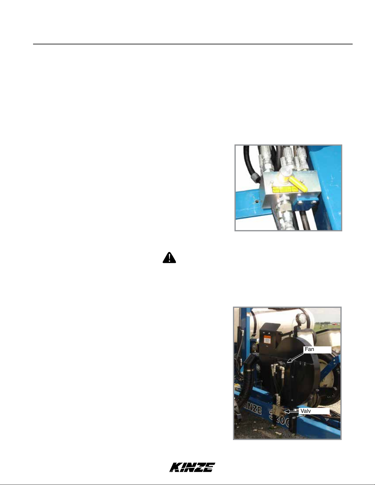
OPTIONAL FOLD CYLINDERS WITH SELECTOR VALVE
A hitch mounted, hand operated selector valve selects row marker or
fold functions. Fold cylinders are mounted on the each side of front
frame and folds wings to/from transport position. Row marker cylinders
raise and lower row markers.
NOTE: Hydraulic pressure will prevent valve from moving.
Release hydraulic pressure from system before attempting to
move selector valve handle.
CAUTION
Operating vacuum fan with cover removed can cause serious injury
from contact with high speed blades or blowing debris. never operate
fan with cover removed.
EDGEVAC FAN MOTOR AND VALVE BLOCK ASSEMBLY (If equipped)
Hydraulically operated motor requires maximum flow rate of 13 GPM
@ 2000 PSI to operate properly. It must be connected to a zero
pressure case drain and connected to the correct pressure and return
SCV's or PTO fittings.
A pressure relief valve in the valve block assembly prevents build up of
oil pressure over 35 PSI in case drain line when vacuum fan motor is
in operation. This valve vents oil outside of valve block through a drain
hole in the aluminum valve block. This can occur whenever the case
drain is improperly connected or motor circuit pressure is too high.
See “Hydraulic System Schematic - Vacuum Fan Motor System” in
Lubrication and Maintenance section.
The valve block also contains a check valve that prevents vacuum fan
from operating in wrong direction if pressure is applied to of motor
return side and allows fan to coast to a stop when tractor hydraulic
control is returned to neutral.
Selector valve
Fan motor
Valve block
NOTE: Fan turns at a reduced speed if reverse pressure is applied.
EdgeVac fan assembly
6/11 2-3
TM
Machine Operation
M0241-01Model 3200
Following information is general in nature to aid in preparation of tractor and planter for use, and to provide general
operating procedures. Operator experience, familiarity with the machine, and the following information should combine
for efficient planter operation and good working habits.
Improperly operating or working on this equipment could result in
death or serious injury. Read and follow all instructions in Operator
Manual before operating or working on this equipment.
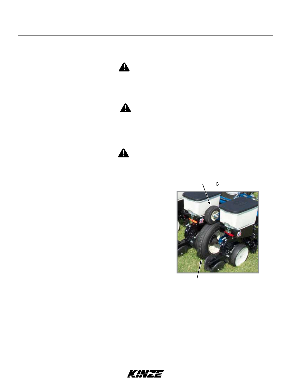
INITIAL PREPARATION
Loose transport wheel lug bolts can result in wheel separation
from planter and cause death, serious injury, and damage to
property and equipment. Torque transport wheel "- 18 lug bolts
to 90 ft-lb (122 N-m) before operating planter for the first time and
periodically after.
Explosive separation of rim and tire parts can cause death or serious
injury.Overination,rimandtireservicing,improperuseofrimsandtires,
worn, or improperly maintained tires could result in a tire explosion.
WARNING
WARNING
WARNING
Contact drive
1. Torque transport wheel "- 18 lug bolts to 90 ft-lb (122 N-m).
2. Inflate transport/ground drive tires to 40 psi (275.7 kPa).
3. Inflate contact drive tires to 50 psi (344.7 kPa).
Transport/ground drive
TRACTOR REQUIREMENTS
Consult your dealer for information on horsepower requirements and tractor compatibility. Requirements vary with
planter options, tillage, and terrain.
A 12 volt DC electrical system is required to operate planter safety/warning lights, digital vacuum gauge, and optional
pneumatic down pressure system or work lights.
Two dual remote hydraulic outlets (SCV) are required on all models. An additional SCV and zero pressure case drain,
is required for EdgeVac equipped planters.
Hydraulic maximum flow rate of 13 GPM @ 2000 PSI is required to operate EdgeVac vacuum fan motor.
2-4 6/11
TM
Machine Operation
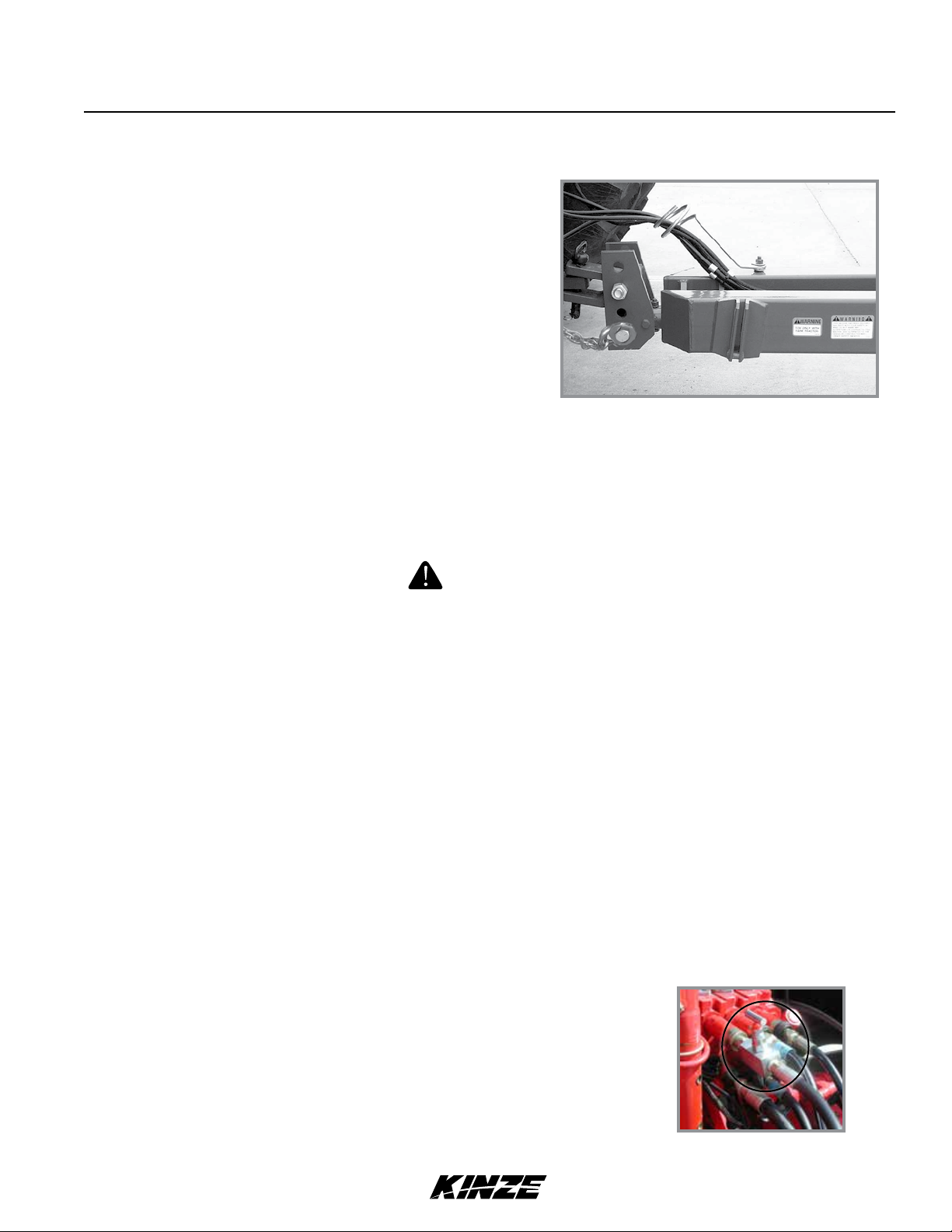
TRACTOR PREPARATION AND HOOKUP
1. Adjust tractor drawbar 13 to 17 inches above ground. Adjust
drawbar so hitch pin hole is directly below center line of PTO
shaft. Make sure drawbar is in a stationary position.
2. Back tractor to planter and connect with a minimum ¾"
diameter hitch pin. Secure with a locking or cotter pin.
NOTE: DO NOT install safety chain using clevis mounting hardware. Safety chain MUST be
installed separately.
Model 3200M0241-01
Drawbar and safety chain connection
3. Safety chain must be used to keep planter and tractor connected in case of a hitch pin/drawbar failure. Attach
safety chain at an unused clevis mounting hole on the planter hitch. Torque hardware to 840 ft-lb (1138.8 N-m).
WARNING
Pressurized hydraulic uid can penetrate body tissue and result
in death, serious infection, or other injuries. Fluid injected under
skin must be IMMEDIATELY removed by a surgeon familiar with this
type of injury. Make sure connections are tight and hoses and
fittings are not damaged before applying system pressure. Leaks
can be invisible. Keep away from suspected leaks. Relieve pressure
before searching for leaks or performing any system maintenance.
NOTICE
Wipe hose ends to remove any dirt before connecting couplers to
tractor ports or contamination may cause equipment failure.
4. Connect hydraulic hoses to tractor ports in a sequence familiar and comfortable to the operator.
NOTICE
EdgeVac fan motor hydraulic hoses and case drain must be installed
correctly. Motor can be damaged or equipment will not operate properly.
" hose from motor - Case Drain (CD - Orange or CD - Green)
¾" hose from motor - Return
½" hose to motor - Pressure
NOTE:Iftractorisequippedwithanadjustableowoutlet(SCV),settofull
owposition.Fortractorsnotequippedwithamethodforniteadjustment
ofhydraulicow,FlowControlNeedleValveKitG1K426isavailablefrom
Kinze Repair Parts through your Kinze Dealer.
G1K426 needle valve kit
6/11 2-5
TM
Machine Operation
M0241-01Model 3200
TRACTOR PREPARATION AND HOOKUP (CONTINUED)
5. Connect ASABE Standards 7 terminal connector for safety/warning lights on planter to ASABE Standards
receptacle on tractor. If your tractor is not equipped with an ASABE Standards receptacle, check with your tractor
manufacturer for availability. Check warning lights on planter work in conjunction with warning lights on tractor.
NOTE: A 12 volt battery connection is required to power the vacuum fan digital gauge. Connect
“red” wire to positive (+) battery terminal and “black” wire to negative (-) battery terminal.
Jack stand in stored position
6. Raise jack stand and remount horizontally on storage bracket.
LEVEL PLANTER
Same distance from ground.
Level planter
Lateral adjustment is maintained by tire pressure. Check tires are inflated to specification.
Front and rear level adjustment is maintained by hitch clevis position unless tractor drawbar is adjustable for height.
Planter frame and row unit parallel arms must be level for proper planter and row unit operation. Bottom of toolbar
should be 20" to 22" from planting surface.
1. Lower planter to planting position and check planter is level front to rear. Go to step 2 if hitch is too high or low.
NOTE: DO NOT install safety chain using clevis hardware. Move safety chain location if necessary.
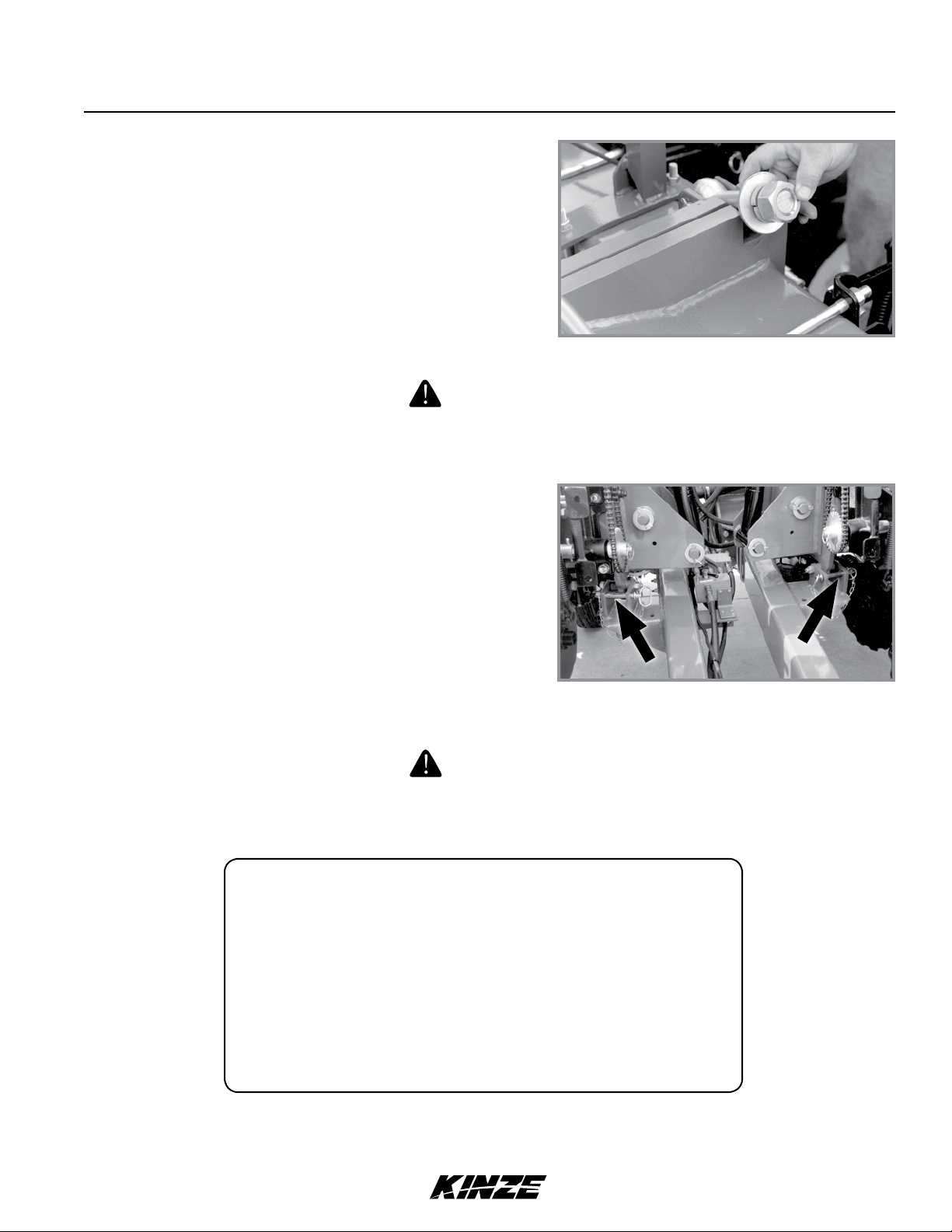
2. Remove clevis hitch hex head cap screw and lock nut using a torque wrench. Replace if off-torque is below
75 ft-lb (101.6 N-m) or there is corrosion or damage.
NOTE: Clevis must be free to move on hitch. DO NOT OVERTIGHTEN hardware.
3. Align clevis to hitch holes at new location and install hex head cap screw and lock nut. Tighten lock nut until
threads are fully engaged and hex head cap screw and lock nut are firmly against hitch bracket.
4. Recheck with planter in field.
2-6 6/11
TM
Machine Operation
MANUAL WING FOLD TRANSPORT TO FIELD OPERATION
WARNING
Planter wings may swing suddenly and cause death or serious injury.
Do not stand between wings and frame when folding or unfolding
planter. Planter must be on a level surface in all directions.
SUMMARIZED TRANSPORT TO FIELD SEQUENCE
• With center lift cylinders retracted and lockups in place, remove
wing lock pins and fold wings out.
• Swing wing locking eyebolts into place.
• Extend lift cylinders.
• Remove center section lift cylinder lockups.
• Lower planter.
• Tighten wing locking eyebolts.
• Release turnbuckle at center of planter.
NOTE: Read following information for detailed instructions.
Model 3200M0241-01
NOTE: Use special wrench stored on inside of hitch for center turnbuckle and wing lock eyebolt
hex nuts. Always return wrench to storage location after use.
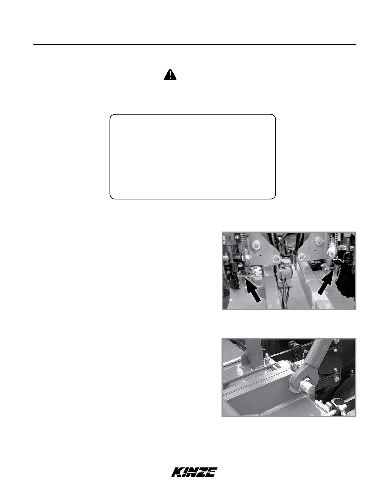
1. With planter raised and cylinder lockups in place, remove w ing
lock pins at marker support and hitch. Fold wings out
to operating position.
NOTE: If wing lift tires are not raised, with cylinder lockups
in place on four center section lift cylinders, move tractor
hydraulic control to lowering position until cylinders are
fully retracted and wing tires are fully raised.
2. Swing wing locking eyebolts into position to lock each wing.
3. Operate hydraulic lever to extend lift cylinders. (Wing wheel
cylinders may not fully extend.)
4. Remove cylinder lockups from four center section lift
cylinders and place them in storage positions on wheel
modules.
Wing lock pin locations
5. Lower planter. Hold tractor hydraulic control 5 to 10 seconds
with cylinders fully retracted to rephase system.
Securing wing lock eyebolt
6. Tighten wing lock 1¼" hex nuts.
6/11 2-7
TM
Machine Operation
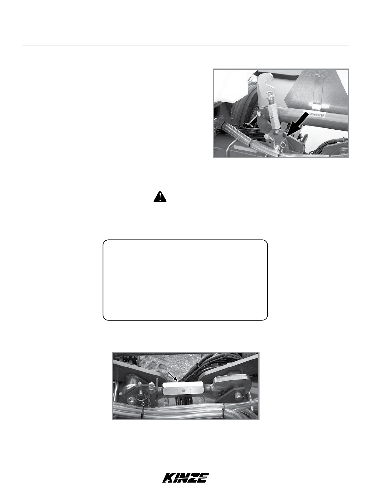
7. Release center turnbuckle and raise upright. Secure in
position with lockup pin.
MANUAL WING FOLD FIELD OPERATION TO TRANSPORT
WARNING
Planter wings may swing suddenly and cause death or serious injury.
Do not stand between wings and frame when folding or unfolding
planter. Planter must be on a level surface in all directions.
M0241-01Model 3200
Center turnbuckle lockup pin
SUMMARIZED FIELD TO TRANSPORT SEQUENCE
• Raise row markers and lower planter.
• Position turnbuckle to hold frame in level position.
• Loosen wing locking eyebolts and swing over to unlock wings.
• Raise planter.
• Install lockups on center lift cylinders.
• Retract wing lift cylinders.
• Fold wings forward and lock in place.
NOTE: Read following information for detailed instructions.
NOTE: Use special wrench stored on inside of hitch for center turnbuckle and wing lock eyebolt
hex nuts. Always return wrench to storage location after use.
Center turnbuckle installation
1. Fold row markers to raised transport position and lower planter to ground.
2. Swing center turnbuckle into position to hold planter frame level and tighten slightly. Install lockup pin in storage
location
2-8 6/11
TM
Machine Operation
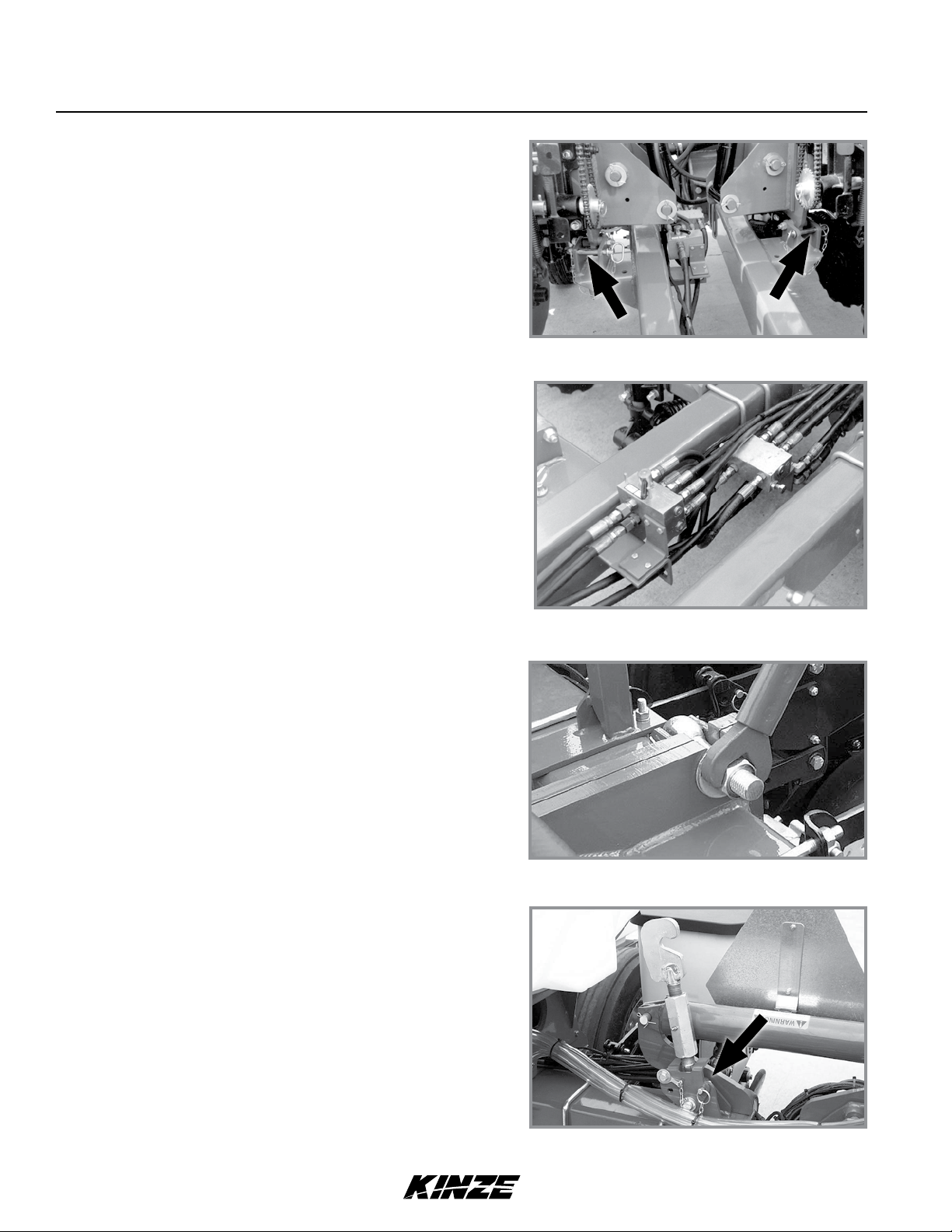
3. Loosen wing lock 1¼" hex nuts and swing wing lock
eyebolts over to release planter wings.
4. Raise planter.
5. Install cylinder lockups on four center section lift cylinders.
6. Place tractor hydraulic control in lowering position and hold
until wing cylinders are fully retracted and wing tires are fully
raised.
WARNING
Uncontrolled wing movement can cause death, serious injury, and
damage to property and equipment. Make sure wings are properly
locked in place before moving planter
Model 3200M0241-01
Wing lock eyebolt
7. Fold each wing forward into transport position and lock wings in
place at marker support and hitch with wing safety pins.
HYDRAULIC WING FOLD TRANSPORT TO FIELD OPERATION
WARNING
Planter wings may swing suddenly and cause death or serious injury.
Do not stand between wings and frame when folding or unfolding
planter. Planter must be on a level surface in all directions.
SUMMARIZED TRANSPORT TO FIELD SEQUENCE
• With center lift cylinders retracted and lockups in place, remove wing lock pins.
• Move selector valve to “FOLD”.
• Hydraulically fold wings out.
• Swing wing locking eyebolts into place.
• Extend lift cylinders.
• Remove center section lift cylinder lockups.
• Lower planter.
• Tighten wing locking eyebolts.
• Release turnbuckle at center of planter.
• Move selector valve to “MARKER”.
Wing lock pin locations
NOTE: Read following information for detailed instructions.
NOTE: Use special wrench stored on inside of hitch for center turnbuckle and wing lock eyebolt
hex nuts. Always return wrench to storage location after use.
6/11 2-9
TM
Machine Operation
1. With planter raised and cylinder lockups in place, remove
wing lock pins at marker support and hitch. Fold wings out
to operating position.
NOTE: If wing lift tires are not raised, with cylinder lockups
in place on four center section lift cylinders, move tractor
hydraulic control to lowering position until cylinders are fully
retracted and wing tires are fully raised.
NOTE: Hydraulic pressure will prevent selector valve from
moving. Release hydraulic pressure from system before
attempting to move selector valve handle.
2. Move selector valve to “FOLD”.
M0241-01Model 3200
Wing lock pin locations
3. Move the tractor hydraulic control and fold the wings out to
operating position.
4. Swing wing lock eyebolts into position to lock each wing.
5. Operate the hydraulic lever to extend the lift cylinders. (Wing
wheel cylinders may not fully extend)
6. Remove four center section cylinder lockups from cylinders
and place them in wheel module storage positions.
7. Lower planter. Hold tractor hydraulic control 5 to 10 seconds
with cylinders fully retracted to rephase system.
8. Tighten wing lock 1¼" hex nuts.
9. Release center turnbuckle and raise upright. Secure in
position with lockup pin.
Selector valve
Securing wing lock eyebolt
NOTE: Hydraulic pressure will prevent selector valve from
moving. Release hydraulic pressure from system before
attempting to move selector valve handle.
10. Move selector valve to “MARKER”.
Center turnbuckle lockup pin
2-10 6/11
TM
Machine Operation
HYDRAULIC WING FOLD FIELD OPERATION TO TRANSPORT
WARNING
Planter wings may swing suddenly and cause death or serious injury.
Do not stand between wings and frame when folding or unfolding
planter. Planter must be on a level surface in all directions.
SUMMARIZED FIELD TO TRANSPORT SEQUENCE
• Raise row markers and lower planter.
• Position turnbuckle to hold frame in level position.
• Move selector valve to “FOLD”.
• Loosen wing lock eyebolts and swing over to unlock wings.
• Raise planter.
• Install lockups on center lift cylinders.
• Retract wing lift cylinders.
• Hydraulically fold wings forward. Lock wings in place.
• Move selector valve to “MARKER”.
NOTE: Read following information for detailed instructions.
Model 3200M0241-01
NOTE: Use special wrench stored on inside of hitch for center turnbuckle and wing lock eyebolt
hex nuts. Always return wrench to storage location after use.
Center turnbuckle installation
1. Fold row markers to raised transport position and lower planter to ground.
2. Swing center turnbuckle into position to hold planter frame level and tighten slightly. Install lockup pin in storage
location
NOTE: Hydraulic pressure will prevent selector valve from
moving. Release hydraulic pressure from system before
attempting to move selector valve handle.
3. Move selector valve to “FOLD”.
Selector valve
6/11 2-11
TM
Machine Operation
4. Loosen wing lock 1¼" hex nuts and swing wing lock eyebolts
over to release planter wings.
5. Raise planter.
6. Install cylinder lockups on four center section lift cylinders.
7. Place tractor hydraulic control in lowering position and hold until
wing cylinders are fully retracted and wing tires are fully raised.
WARNING
Uncontrolled wing movement can cause death, serious injury, and
damage to property and equipment. Make sure wings are properly
locked in place before moving planter
M0241-01Model 3200
Wing lock eyebolt
8. Fold each wing forward into transport position and lock wings
in place at marker support and hitch with wing safety pins.
Wing lock pin locations
HYDRAULIC ROW MARKER OPERATION
DANGER!
Contacting or coming close to power lines or other high energy
sources will cause death or serious injury. Keep away from power
lines or high energy sources at all times.
WARNING
Row marker can lower at any time and could cause death or serious
injury. Stay away from row markers at all times.
All Model 3200 planters are equipped with a dual valve hydraulic system. The dual valve system allows the row
markers to be operated independently of the planter lift cylinders. Each time a marker is raised, the sequencing valve
directs flow to lower the opposite marker.
Both markers can be used at the same time. Lower planter and selected marker. Move tractor control lever to raise
position and immediately return it to lower position. This shifts the marker control valve and remaining marker will be
lowered.
NOTE: A hand operated selector valve selects row marker or wing fold functions on machines with
hydraulic wing fold option. Remove pressure from hydraulic system before attempting to move
selector handle.
2-12 6/11
TM

ROW MARKER SPEED ADJUSTMENT
Excessive row marker travel speed can damage row markers.
Adjustowcontrolsbeforerowmarkersarerstused.
Marker lower flow control
Machine Operation
Model 3200M0241-01
NOTICE
Marker raise flow control
Rowmarkerowcontrolvalves
Two flow control valves determine amount of oil flow restriction controlling row marker travel speeds. One flow control
valve controls lowering speed and one controls raising speed of both markers.
NOTE 1: Hydraulics operate slowly when oil is cold. Make all adjustments with oil warm.
NOTE2:Onatractorwhereoilowcannotbecontrolled,tractorowratemaybegreaterthan
rate marker cylinder can accept. Hold tractor hydraulic control lever until cylinder reaches end of
its stroke. This occurs most often on tractors with an open center hydraulic system.
NOTE3:Ontractorswithaclosedcenterhydraulicsystem,sethydraulicowcontrolsodetent
functions properly.
1. Loosen jam nut and turn control clockwise (IN) to slow speed or counterclockwise (OUT) to increase speed.
2. Tighten jam nut after adjustments are made.
6/11 2-13
TM
ROW MARKER ADJUSTMENT
Machine Operation
M0241-01Model 3200
1. Multiply number of rows by average row spacing in inches to determine total planting width.
Row Marker Lengths
8 Row 36" 288" (731.5 cm)
8 Row 38" 304" (772.2 cm)
12 Row 30" 360" (914.4 cm)
2. Lower planter and row marker assembly to ground.
3. Measure from planter center line to a point where blade contacts ground.
4. Adjust row marker extension so distance from marker disc blade to center line of planter is equal to total planting
width. Adjust right and left row marker assemblies equally and securely tighten clamping bolts.
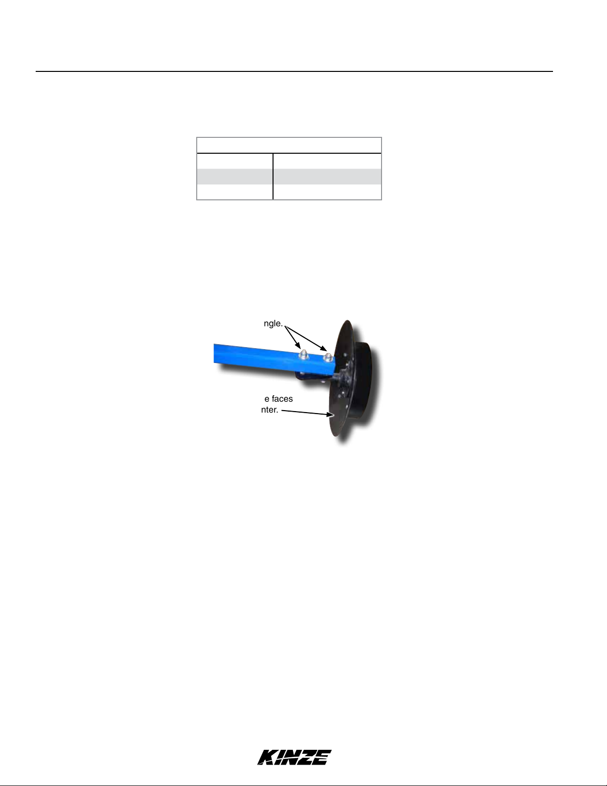
Loosen hardware to adjust blade angle.
Concave side faces
towards planter.
Row marker disc blade angle adjustment
NOTICE
Setting marker disc blade assembly at a sharper angle than needed
adds stress to row marker assembly and shortens bearing and
blade life. Set blade angle only as needed to leave a clear mark.
Marker disc blade is installed with concave side facing inward. Spindle assembly is slotted so hub and blade can be
angled to throw more or less dirt.
5. Loosen hardware and move assembly as required.
6. Tighten bolts to specified torque.
7. Do a field test to ensure markers are properly adjusted.
NOTE: A notched marker blade is available from Kinze through your Kinze Dealer for use in more
severe no till conditions.
2-14 6/11
TM
Machine Operation
TRANSPORTING PLANTER
DANGER!
Contacting or coming close to power lines or other high energy
sources will cause death or serious injury. Keep away from power
lines or high energy sources at all times.
WARNING
Allsafety/warninglights,reectivedecals,andSMVsignmustbe
in place and visible before transporting machine on public roads or
death, serious injury, and damage to property and equipment may
result. Check federal, state/provincial, and local regulations before
transporting equipment on public roads.
• Tow only with farm tractor rated and configured for equipment.
• Know your route and be aware of any obstructions.
Model 3200M0241-01
• Follow all road and bridge load limit restrictions.
• Never exceed maximum transport towing speed of 20 mph (32 kph).
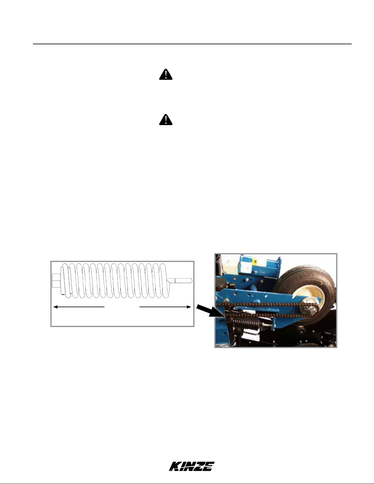
CONTACT DRIVE SPRING ADJUSTMENT
8" (20.3 cm)
Spring length measurement (Factory setting)
Down pressure spring location
There are two down pressure springs on each contact drive wheel. Spring tension is factory preset and normally
requires no adjustment.
Basic setting for spring tension is approximately 200 lb (90.72 kg) of down force at tire contact point.
NOTE: Measurement must be taken in planting position with proper tire pressure.
6/11 2-15
TM
Machine Operation
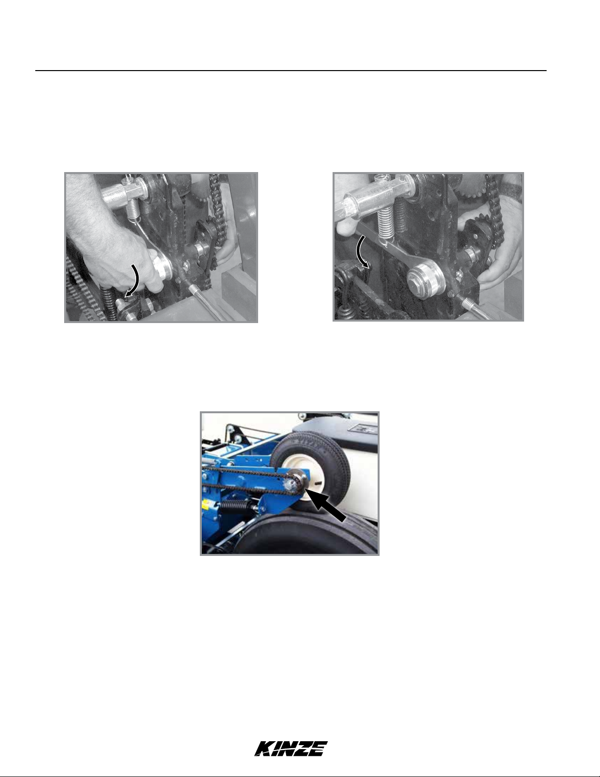
WRAP SPRING WRENCH
Chain idlers use wrap spring wrenches to release and adjust transmission chain tension.
NOTE: Wrap spring wrenches are L.H. and R.H. specific. L.H. styles have silver metal or grey
plastic release collars. R.H. styles have gold metal or blue plastic release collars.
M0241-01Model 3200
Release chain tension
Rotate wrap spring wrench knurled collar while rotating chain idler away from chain to release chain tension.
Rotate chain idler into chain while rotating handle to tension idler spring.
Increase chain tension
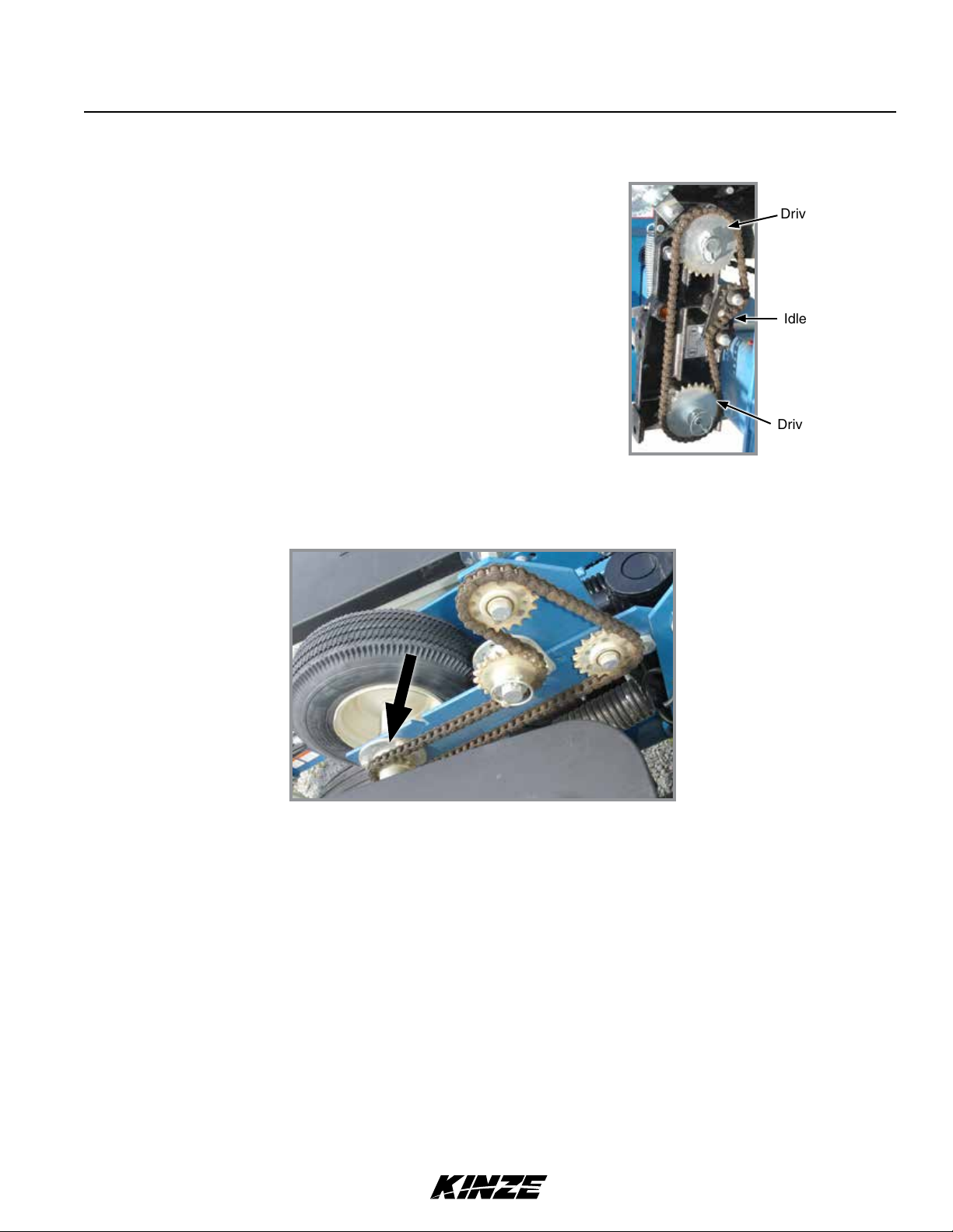
CONTACT WHEEL DRIVE SPROCKETS
Contact wheel drive sprocket
NOTE: 15 tooth, 19 tooth or 30 tooth drive sprockets at each contact drive wheel can be
interchanged from sprocket storage rod bolted to each transmission. 30 tooth sprockets require
use of 124 pitch chains instead of standard 116 pitch No. 40 chains.
Chain tension is controlled by a spring-loaded sprocket idler. Amount of spring tension on chain is controlled by idler
arm. Planting rate chart in Rate Chart section will aid you in selecting correct sprocket.
NOTE: 15, 19, and 30 tooth drive sprockets are NOT applicable to all rate charts. 23 tooth driven
sprocket at reverser plate is changed to a 17 tooth sprocket when using 60 cell soybean seed disc.
Check chart titles to ensure proper rate chart is selected.
NOTE: Make a field check after each sprocket combination adjustment to be sure you are planting
at desired rate.
2-16 6/11
TM
Machine Operation
SEED RATE TRANSMISSION ADJUSTMENT
Model 3200M0241-01
Seed rate transmissions allow simple, rapid changes of sprockets to obtain
desired planting population. By removing lynch pins on hexagon shafts,
sprockets can be interchanged with those from the sprocket storage rod
bolted to the transmission.
Chain tension is controlled by a spring-loaded dual-sprocket idler. The idler
assembly is equipped with an easy-release idler arm to remove spring
tension for replacing sprockets.
Planting rate charts in Rate Chart section will aid you in selecting correct
sprocket combinations.
Seed rate transmission chain tension
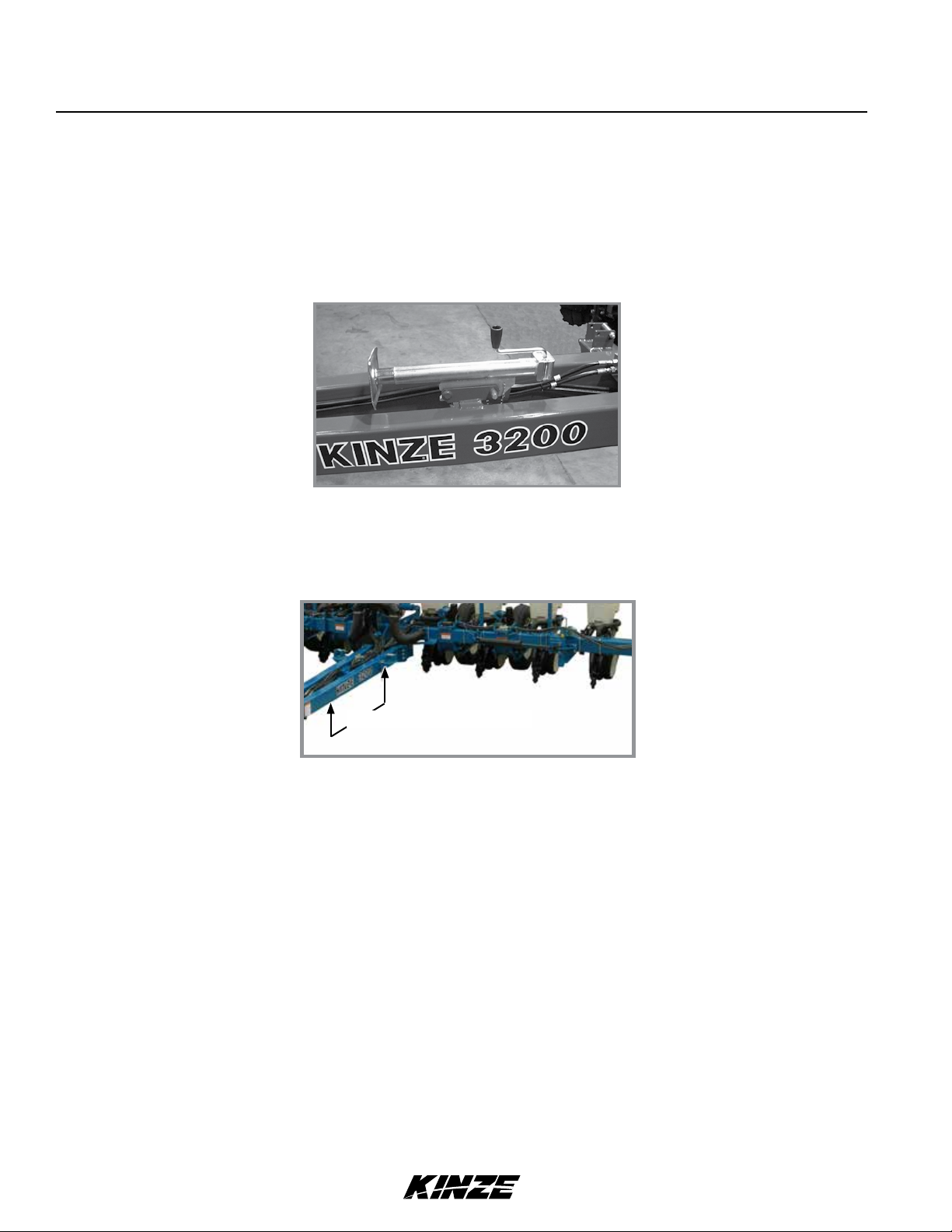
STANDARD AND HALF RATE (2 TO 1) DRIVES
Drive sprocket
Idler
Driven sprocket
Rate drive
Seed planting rate charts are based on the standard rate drive using a 17 tooth sprocket unless otherwise specified.
NOTE: Half rate (2 to 1) drive is recommended only when desired population falls below that on
planting rate charts.
Replacing standard 17 tooth drive sprocket located on inner side of top transmission shaft, with 34 tooth half
rate (2 to 1) drive reduction sprocket reduces planter transmission speed and planting and application rates by
approximately 50%.
NOTE: Do a field check after each sprocket combination adjustment to make sure you are planting
at the desired rate.
6/11 2-17
TM
Machine Operation
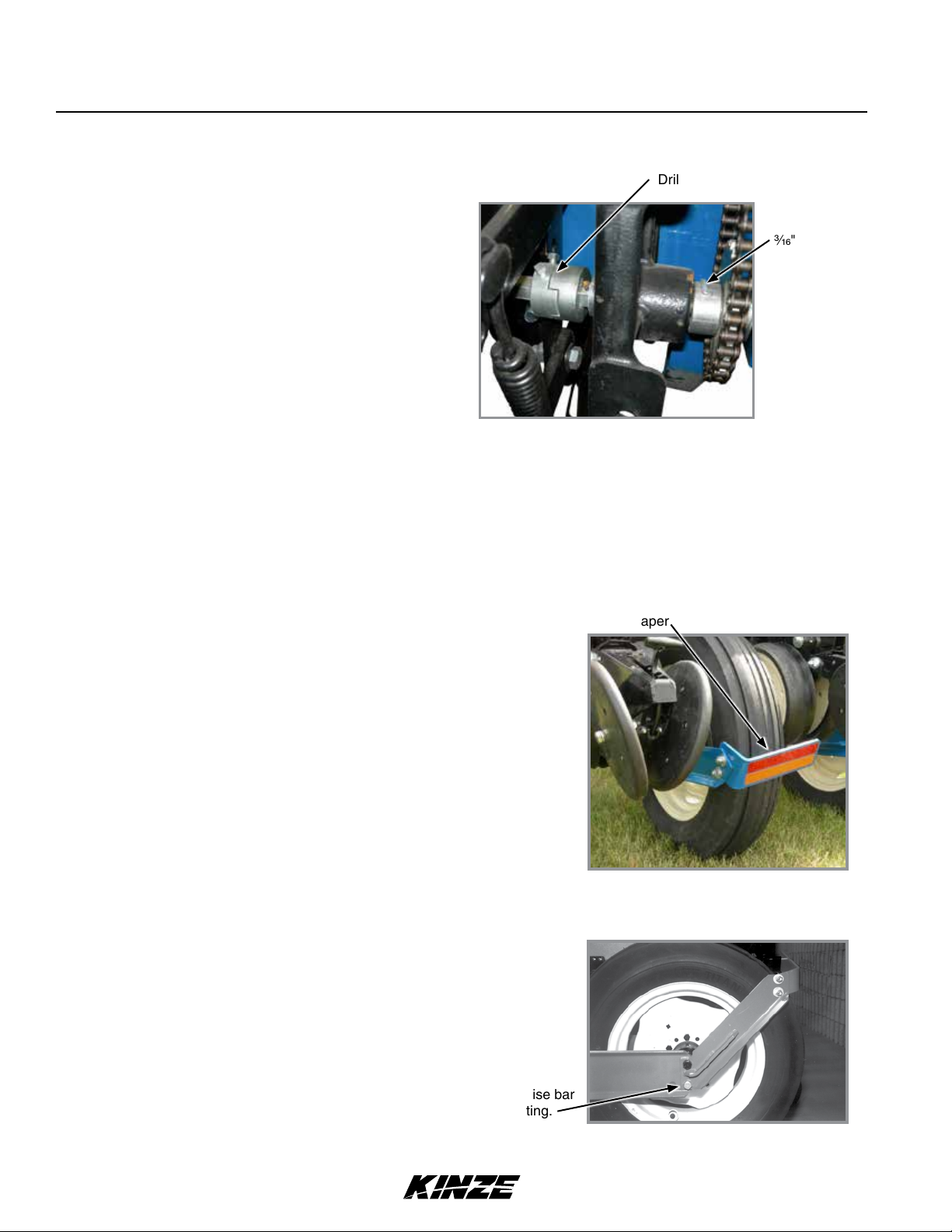
SHEAR PROTECTION
Shear pins protect the planter driveline and row unit
components from damage.
1. Determine where binding has occurred before
replacing a pin. Turn shaft by hand (with the aid of a
wrench) and check for misalignment and seized parts.
2. When shaft can be turned by hand (with the aid of a
wrench) replace shear pins with same size and type.
Spare shear pins are in wheel module storage area.
NOTICE
Misaligned drill shaft/transmission coupler can cause equipment
damage.
M0241-01Model 3200
Drill shaft/transmission coupler
" shear pin
Transmission shaft and drill shaft coupler
3. Check driveline alignment and follow prescribed lubrication schedules to prevent component binding or breakage.
TIRE SCRAPER
Scraper
A tire scraper prevents buildup of dirt and mud between wheel
arm assembly and tire.
Adjust scraper so it does not contact tire.
Tire scraper
RIDGE PLANTING
Planter toolbar height can be raised 3" for ridge planting.
Relocate 20" transport axles to lower hole in wheel arm.
Install axle here to raise bar
height for ridge planting.
Ridge planting adjustment
2-18 6/11
TM
 Loading...