

Kinze 3110 User Manual

MODEL 3110
RIGID MOUNTED PLANTER
OPERATOR’S MANUAL
M0244-01 Rev. 7/14
This manual is applicable to: Model 3110 Mounted Planter
2013 to 2014 production
Record the model number and serial number of your planter along with date purchased:
Model Number ____________ 3110 _________________
Serial Number ___________________________________
Date Purchased __________________________________
Monitor Serial Number _______________________________________________
Measured Pulses Per Mile/Km (Radar Distance Sensor) ____________________
Measured Pulses Per Mile/ Km (Magnetic Distance Sensor) _________________
SERIAL NUMBER
The serial number plate is located on the planter frame to be readily available. It is suggested that your serial number
and purchase date also be recorded above.
The serial number provides important information about your planter and may be required to obtain the correct
replacement part. Always provide the model number and serial number to your Kinze Dealer when ordering parts or
anytime correspondence is made with Kinze Manufacturing, Inc.
Serial number plate location - R.H. side of 3-point mount
Kinze®, the Kinze® logo, and EdgeVac® are registered trademarks of Kinze Manufacturing, Inc.

This page left blank intentionally.

Predelivery/Delivery Checklist
Model 3110M0244-01
TO THE DEALER
Predelivery service includes assembly, lubrication, adjustment, and test. This service makes sure planter is delivered to
the retail customer/end user ready for field use.
PREDELIVERY CHECKLIST
Use the following checklist and inspect planter after it is completely assembled. Check off each item found satisfactory
or after proper adjustment is made.
Row units properly spaced and optional attachments correctly assembled.
EdgeVac components properly installed (as applicable).
All grease fittings in place and lubricated.
All working parts move freely, bolts are tight, and cotter pins are spread.
Check all drive chains for proper tension and alignment.
Check for oil leaks and proper hydraulic operation.
Hydraulic hoses correctly routed to prevent damage.
Inflate tires to specified air pressure and torque wheel lug bolts and lug nuts as specified in the manual.
All safety decals correctly located and legible. Replace if damaged.
All reflective decals and SMV sign correctly located and visible when the planter is in transport position.
Safety/warning lights correctly installed and working properly.
Paint all parts scratched in shipment or assembly.
All safety lockup devices on the planter and correctly located.
Auxiliary safety chain properly installed and hardware torqued to specification.
This planter has been thoroughly checked and to the best of my knowledge is ready for delivery to the retail
customer/end user.
(Signature Of Set-Up Person/Dealer Name/Date)
RETAIL CUSTOMER/END USER
Name Delivery Date
Street Address Model No. 3110 Serial No.
City, State/Province Dealer Name
ZIP/Postal Code Dealer No.
9/12 1
TM

Predelivery/Delivery Checklist
M0244-01Model 3110
DELIVERY CHECKLIST
Use the following checklist at time planter is delivered as a reminder of very important information which should be
conveyed to retail customer/end user. Check off each item as it is fully explained.
Check for proper operation of vacuum fan (If applicable) with tractor to be used with planter.
Life expectancy of this or any other machine is dependent on regular lubrication as directed in the Operator Manual.
All applicable safety precautions.
Along with retail customer/end user, check reflective decals and SMV sign are clearly visible with planter in transport
position and attached to tractor. Check safety/warning lights are in working condition. Tell retail customer/end user
to check federal, state/provincial, and local regulations before towing or transporting on a road or highway.
Give Operator Manual, Parts Manual, and all Instruction Sheets to retail customer/end user and explain all operating
adjustments.
Read warranty to retail customer/end user.
Complete Warranty and Delivery Report form.
To the best of my knowledge this machine has been delivered ready for field use and customer has been fully
informed as to proper care and operation.
(Signature Of Delivery Person/Dealer Name/Date)
AFTER DELIVERY CHECKLIST
The following is a list of items we suggest to check during the first season of use of the equipment.
Check planter performance with retail customer/end user.
Check performance of EdgeVac or mechanical seed metering system with retail customer/end user.
Review importance of proper maintenance and adherence to all safety precautions with retail customer/end user.
Check for parts that may need to be adjusted or replaced.
Check all safety decals, reflective decals, and SMV sign are correctly located as shown in the Parts Manual and that
decals are legible. Replace if damaged or missing.
Check safety/warning lights are working properly.
(Signature Of Follow-Up Person/Dealer Name/Date)
All registrations must be submitted online at “business.kinze.com” within 5 business days of delivery.
Retain a copy of this form for auditing purposes.
Tear Along Perforation
2 Rev. 6/14
TM

Table of Contents
Model 3110M0244-01
MACHINE OPERATION
Row Marker Lockups (Conventional Row Markers Only) 2-1
Initial Preparation ................................2-2
Tractor Requirements. . . . . . . . . . . . . . . . . . . . . . . . . . . . . 2-3
Tractor Preparation and Hookup ....................2-4
Leveling the Planter . . . . . . . . . . . . . . . . . . . . . . . . . . . . . . 2-6
Toolbar Height Adjustment. . . . . . . . . . . . . . . . . . . . . . . . . 2-6
Parking Stand Adjustment . . . . . . . . . . . . . . . . . . . . . . . . .2-7
Seed Rate Transmission Adjustment . . . . . . . . . . . . . . . . .2-8
Contact Wheel Drive Sprockets . . . . . . . . . . . . . . . . . . . . .2-8
Contact Wheel Spring Adjustment. . . . . . . . . . . . . . . . . . . 2-9
Shear Protection ................................2-9
Wrap Spring Wrench .............................2-9
EdgeVac System ...............................2-10
Digital Vacuum Gauge Operation. . . . . . . . . . . . . . . . . . . 2-10
Analog Vacuum Gauge ..........................2-10
Vacuum Fan Motor Valve Block Assembly . . . . . . . . . . . . 2-11
Row Marker Operation ...........................2-11
Row Marker Speed Adjustment . . . . . . . . . . . . . . . . . . . . 2-12
Row Marker Adjustments. . . . . . . . . . . . . . . . . . . . . . . . . 2-13
Point Row Clutches . . . . . . . . . . . . . . . . . . . . . . . . . . . . . 2-14
Front Mounted Drive Wheel Option .................2-15
Planting Speed ................................2-15
Field Test .....................................2-15
Check Seed Population ..........................2-16
Determining Pounds Per Acre (Brush-Type Meter) .....2-17
Determining Bushels Per Acre. . . . . . . . . . . . . . . . . . . . . 2-17
Field Check Granular Chemical Application ..........2-18
ROW UNIT OPERATION
Planting Depth . . . . . . . . . . . . . . . . . . . . . . . . . . . . . . . . . .3-1
“V” Closing Wheel Adjustment (Rubber or Cast Iron) ....3-1
Closing Wheel Shield (Rubber or Cast Iron “V” Closing
Wheels) . . . . . . . . . . . . . . . . . . . . . . . . . . . . . . . . . . . . . 3-2
Drag Closing Attachment. . . . . . . . . . . . . . . . . . . . . . . . . . 3-2
Covering Discs/Single Press Wheel Adjustment ........3-3
Brush-Type Seed Meter . . . . . . . . . . . . . . . . . . . . . . . . . . . 3-4
Finger Pickup Seed Meter . . . . . . . . . . . . . . . . . . . . . . . . .3-5
EdgeVac Seed Meters ............................3-6
Seed Meter Cleanout. . . . . . . . . . . . . . . . . . . . . . . . . . . . . 3-9
Additives .....................................3-10
Seed Hoppers .................................3-11
Seed Meter Drive Release. . . . . . . . . . . . . . . . . . . . . . . . 3-11
Row Unit Extension Brackets. . . . . . . . . . . . . . . . . . . . . . 3-11
Row Unit Chain Routing. . . . . . . . . . . . . . . . . . . . . . . . . . 3-12
Quick Adjustable Down Force Springs Option ........3-13
Frame Mounted Coulter (Pull Row Only). . . . . . . . . . . . . 3-14
Residue Wheels (for Frame Mounted Coulter). . . . . . . . . 3-14
Row Unit Mounted Disc Furrower (Pull Row Only) .....3-15
Row Unit Mounted Bed Leveler (Pull Row Only) .......3-15
Row Unit Mounted Residue Wheel .................3-16
Row Unit Mounted No Till Coulter ..................3-17
Coulter Mounted Residue Wheels . . . . . . . . . . . . . . . . . . 3-18
Granular Chemical Hopper and Drive ...............3-19
Spring Tooth Incorporator ........................3-19
Granular Chemical Banding Options . . . . . . . . . . . . . . . .3-20
Granular Chemical Bander Shield . . . . . . . . . . . . . . . . . .3-20
MONITOR OPERATION .....................5-1
LUBRICATION AND MAINTENANCE
Lubrication . . . . . . . . . . . . . . . . . . . . . . . . . . . . . . . . . . . . .6-1
Lubrication Symbols .............................6-1
Sealed Bearings ................................6-1
Drive Chains ...................................6-1
Bushings ......................................6-3
Wrap Spring Wrench Assembly. . . . . . . . . . . . . . . . . . . . . 6-4
Wheel Bearings . . . . . . . . . . . . . . . . . . . . . . . . . . . . . . . . . 6-4
Grease Fittings .................................6-5
Mounting Bolts and Hardware ......................6-7
Tire Pressure . . . . . . . . . . . . . . . . . . . . . . . . . . . . . . . . . . .6-8
Model 3110 Operating Tire Pressure. . . . . . . . . . . . . . . . . 6-8
Chain Tension Adjustment . . . . . . . . . . . . . . . . . . . . . . . . . 6-9
Finger Pickup Seed Meter Inspection/Adjustment. . . . . . 6-10
Cleaning Finger Pickup Seed Meter For Storage ......6-11
Brush-Type Seed Meter Maintenance ...............6-12
Cleaning Brush-Type Seed Meter For Storage ........6-13
Vacuum Manifold Maintenance ....................6-13
EdgeVac Seed Meter Maintenance . . . . . . . . . . . . . . . . . 6-14
EdgeVac Seed Meter Cleanout ....................6-14
Drag Closing Attachment ........................6-15
Gauge Wheel Adjustment ........................6-15
Gauge Wheel Arm Bushing/Seal Replacement. . . . . . . . 6-16
Gauge Wheel Arm Pivot Spindle Replacement . . . . . . . . 6-16
15" Seed Opener Disc Blade/Bearing Assembly .......6-17
Seed Tube Guard/Inner Scraper ...................6-18
Frame Mounted Coulter .........................6-18
Residue Wheels (For Use With Frame Mounted Coulter) 6-18
Row Unit Mounted Disc Furrower ..................6-19
Row Unit Mounted Bed Leveler . . . . . . . . . . . . . . . . . . . . 6-19
Row Unit Mounted No Till Coulter ..................6-19
Coulter Mounted Residue Wheels . . . . . . . . . . . . . . . . . . 6-20
Row Unit Mounted Residue Wheel .................6-20
Granular Chemical Attachment ....................6-20
9/12 1-1
TM

Spring Tooth Incorporator ........................6-20
Single Point Row Clutch Maintenance ...............6-21
Row Marker Sequencing/Flow Control Valve Inspection 6-22
Row Marker Bearing Lubrication or Replacement . . . . . . 6-23
Wheel Bearing Repack or Replacement .............6-24
EdgeVac Check Valve Inspection ..................6-24
EdgeVac Relief Valve Cartridge Inspection ..........6-24
Preparing Planter for Storage .....................6-25
Electrical Wiring Diagram for Light Package ..........6-26
Electrical Wiring Diagrams for Point Row Clutches .....6-27
Hydraulic Diagram - Vacuum Fan Motor System .......6-28
TROUBLESHOOTING
Brush-Type Seed Meter . . . . . . . . . . . . . . . . . . . . . . . . . . . 7-1
Closing Wheel ..................................7-1
EdgeVac Seed Meter. . . . . . . . . . . . . . . . . . . . . . . . . . . . . 7-2
Finger Pickup Seed Meter . . . . . . . . . . . . . . . . . . . . . . . . .7-4
KPM III Electronic Seed Monitor . . . . . . . . . . . . . . . 7-5
Point Row Clutch ................................7-6
Row Marker Operation ............................7-7
Table of Contents
M0244-01Model 3110
1-2 9/12
TM

To the Owner
Model 3110M0244-01
Kinze Manufacturing, Inc. would like to thank you for your patronage. We appreciate your confidence in Kinze farm
machinery. Your Kinze planter has been carefully designed to provide dependable operation in return for your investment.
This manual has been prepared to aid you in planter operation and maintenance. It should be considered a
permanent part of the machine and remain with the machine when you sell it.
It is the responsibility of the user to read and understand this Operator Manual before operating this equipment. It
is the user’s responsibility to inspect and service the machine routinely as directed in this Operator Manual. We have
attempted to cover all areas of safety, operation, lubrication and maintenance; however, there may be times when special
care must be taken to fit your conditions.
Throughout this manual the symbol and the words DANGER, WARNING, and CAUTION are used to call attention
to safety information that if not followed, will or could result in death or injury. NOTICE and NOTE are used to call your
attention to important information. The definition of each of these terms follows:
DANGER Indicates a hazardous situation which, if not avoided, will result in death or serious
injury.
WARNING Indicates a hazardous situation which, if not avoided, could result in death or serious
injury.
CAUTION, used with the safety alert symbol, indicates a hazardous situation which, if not avoided,
could result in minor or moderate injury.
NOTICE is used to address practices not related to personal injury.
NOTE: Special point of information or machine adjustment instructions.
WARNING
Read and follow all safety instructions in the equipment manual
before operating or working on this equipment.
WARNING
Some photos in this manual may show safety covers, shields or
lockup devices removed for visual clarity. NEVER OPERATE machine
without all safety covers, shields and lockup devices in place.
NOTE: Some photos in this manual may have been taken of prototype machines. Production
machines may vary in appearance.
NOTE: Some photos and illustrations in this manual show optional attachments installed. Contact
your Kinze Dealer for purchase of optional attachments.
9/12 1-3
TM
Warranty
M0244-01Model 3110
The Kinze Limited Warranty for your new machine is stated on the retail purchaser’s copy of the Warranty And Delivery
Receipt form. Additional copies of the Limited Warranty can be obtained through your Kinze Dealer.
Warranty, within the warranty period, is provided as part of Kinze’s support program for registered Kinze products which
have been operated and maintained as described in this manual. Evidence of equipment abuse or modification beyond
original factory specifications will void the warranty. Normal maintenance, service and repair is not covered by Kinze
warranty.
To register your Kinze product for warranty, a Warranty And Delivery Receipt form must be completed by the Kinze
Dealer and signed by the retail purchaser, with copies to the Dealer, and to the retail purchaser. Registration must be
completed and submitted to Kinze Manufacturing, Inc. within 5 business days of delivery of the Kinze product to the retail
purchaser. Kinze Manufacturing, Inc. reserves the right to refuse warranty on serial numbered products which have not
been properly registered.
If service or replacement of failed parts which are covered by the Limited Warranty are required, it is the user’s responsibility
to deliver the machine along with the retail purchaser’s copy of the Warranty And Delivery Receipt to the Kinze Dealer
for service. Kinze warranty does not include cost of travel time, mileage, hauling or labor. Any prior arrangement made
between the Dealer and the retail purchaser in which the Dealer agrees to absorb all or part of this expense should be
considered a courtesy to the retail purchaser.
Kinze warranty does not include cost of travel time, mileage, hauling or labor.
1-4 9/12
TM

Specifications
Model 3110M0244-01
GENERAL INFORMATION
The Model 3110 Mounted Planter is available with EdgeVac or mechanical meters, conventional hoppers, and various
other options. Contact your Kinze dealer for additional options which may be available for your specific model year planter.
Information in this manual was current at time of printing. However, due to Kinze’s ongoing product improvement,
production changes may cause your machine to appear slightly different in detail. Kinze Manufacturing, Inc. reserves the
right to change specifications or design without notice and without incurring obligation to install the same on machines
previously manufactured.
Right hand (R.H.) and left hand (L.H.), as used throughout this manual, are determined by facing in the direction the
machine will travel when in use, unless otherwise stated.
SPECIFICATIONS
Planter Size 6 Row 30" 6 Row 36"/40" 8 Row 30" 8 Row 36"/40"
Width - Transport
(Includes Markers)
Width - Planting 17'-8" (5.4M) 21"-0" (6.4M) 21'-10" (6.7M) 27'-8" (8.4M)
Weight (Mechanical) 2483 lb. (1105.86 kg) 2560 lb. (1161.2 kg) 3092 lb. (1402.5 kg) 3494 lb. (1584.85 kg)
Weight (EdgeVac) 2763 lb. (1253.28 kg) 2854 lb. (1294.55 kg) 3407 lb. (1545.4 kg) 3830 lb. (1737.26 kg)
Toolbar 7" x 7" x ¼" wall 7" x 7" x ¼" wall 7" x 7" x ¼" wall 7" x 7" x ¼" wall
Seed Capacity 1.75 bu. (EdgeVac/Hopper); 1.90 bu. (Mechanical/Hopper)
17'-8" (5.4M) 21"-0" (6.4M) 21'-10" (6.7M) 27'-8" (8.4M)
Tires
Drive System
Seed Transmission
Drive/Drill Shafts
Two 7.60" x 15" 8 ply - adjustable height
Two 4.10" x 6" spring-loaded contact drive tires with no. 40 chain
Two wheel module-mounted, quick-adjust with machined sprockets and no. 40 chain
' hex drive/drill shafts
TRACTOR HYDRAULIC REQUIREMENTS
Configuration Requirements Description
Base machine with mechanical
meters
Base machine with mechanical
meters and optional row marker
package
Base machine with vacuum
meters (external case drain
required for EdgeVac hydraulic
circuit)
Base machine with vacuum
meters and optional row marker
option (external case drain
required for EdgeVac hydralulic
circuit)
0 SCV 0 gpm No hydraulic requirements
1 SCV 10 gpm
1 SCV 15 gpm #1 SCV: Vacuum metering
2 SCV 25 gpm
#1 SCV: row markers with sequencing/flow control
valve
#1 SCV: Vacuum metering
#2 SCV: row markers with sequencing/flow control
valve
9/12 1-5
TM

General Safety Rules
M0244-01Model 3110
1. Read and understand instructions provided in this
manual and warning labels. Review these instructions
frequently!
2. This machine is designed and built with your safety
in mind. Do not make any alterations or changes to this
machine. Any alteration to design or construction may
create safety hazards.
3. A large portion of farm accidents happen from fatigue
or carelessness. Safe and careful operation of tractor and
planter will help prevent accidents.
4.
Never allow planter to be operated by anyone unfamiliar
with operation of all functions of the unit. Operators must
read and thoroughly understand all instructions given in
this manual before operating or working on equipment.
5. Be aware of bystanders, particularly children! Always
look around to make sure it is safe to start tow vehicle
engine or move planter. This is particularly important with
higher noise levels and quiet cabs, as you may not hear
people shouting.
6. Make sure planter weight does not exceed towing
capacity of tractor, or bridge and road limits. This is critical
to maintain safe control and prevent death or injury, or
property and equipment damage.
7. Never ride or allow others to ride on planter.
8. Store planter in an area away from human activity. DO
NOT permit children to play on or around the stored unit.
15. Use of aftermarket hydraulic, electric, or PTO drives
may create serious safety hazards to you and people
nearby. If you install such drives, follow all appropriate
safety standards and practices to protect you and others
near this planter from injury.
16. Follow all federal, state/provincial, and local
regulations when towing farm equipment on a public
highway. Use safety chain (not an elastic or nylon/
plastic tow strap) to retain connection between towing
and towed machines in the event of primary attaching
system separation.
17. Make sure all safety/warning lights, SMV sign, and
reflective decals are in place and working properly
before transporting the machine on public roads.
18. Limit towing speed to 15 MPH. Tow only with farm
tractor of a minimum 90 HP. Allow for unit length when
making turns.
19. Reduce speed prior to turns to avoid the risk of
overturning. Always drive at a safe speed relative to
local conditions and ensure your speed is slow enough
for a safe emergency stop.
20. Chemical application is often an integral part of
planting. Follow label instructions for proper chemical
mixing, handling and container disposal methods.
21. Be familiar with safety procedures for immediate
first aid should you accidentally contact chemical
substances.
9. Keep hands, feet, and clothing away from moving parts.
Do not wear loose-fitting clothing which may catch in
22. Use the proper protective clothing and safety
equipment when handling chemicals.
moving parts.
10. Always wear protective clothing, shoes, gloves,
hearing, and eye protection applicable for the situation.
11. Do not allow anyone to stand between tongue or hitch
and towing vehicle when backing up to planter.
13. Prevent electrocution, other injuries, or property
and equipment damage. Watch for obstructions such as
wires, tree limbs, etc. when operating machine. Be aware
of clearances during turns and when folding/unfolding
planter.
14. Reinstall all guards removed for maintenance
activities. Never leave guards off during operation.
1-6 9/12
23. Chemicals are supplied with Material Safety Data
Sheets (MSDS) that provide full information about the
chemical, its effects on exposure, and first aid needs
in the event of an emergency. Keep your MSDS file
up-to-date and available for first responders in case of
emergency.
24. When servicing ground engaging components such
as opening disks and firming points, use special care to
avoid points and edges worn sharp during use.
25. Use professional help if you are unfamiliar with
working on hydraulic systems. Pressurized hydraulic
fluid can penetrate body tissue and result in death,
serious infection, or other injuries.
TM

Safety Instructions, Signs, and Decals
Model 3110M0244-01
Following are some common hazard warnings associated with this equipment. Pay close attention to all safety,
operating, and maintenance information in this manual and decals applied to your equipment.
DANGER!
Contacting or coming close to power lines or other high energy
sources will cause death or serious injury. Keep away from power
lines or high energy sources at all times.
WARNING
Improperly operating or working on this equipment could result in
death or serious injury. Read and follow all instructions in Operator
Manual before operating or working on this equipment.
WARNING
Falling equipment can cause death or serious injury. Install all lockup
devices or lower planter to ground before working on equipment.
WARNING
Explosive separation of rim and tire parts can cause death or serious
injury.Overination.rimandtireservicing,improperuseofrimsandtires,
or worn or improperly maintained tires could result in a tire explosion.
SAFETY SIGNS AND DECALS
WARNING
Allsafety/warninglights,reectivedecals,andSMVsignmustbe
in place and visible before transporting machine on public roads or
death, serious injury, and damage to property and equipment may
result. Check federal, state/provincial, and local regulations before
transporting equipment on public roads.
Safety signs and decals are placed on the machine to warn of hazards and provide important operating and maintenance
instructions. Information on these signs are for your personal safety and the safety of those around you. FOLLOW ALL
SAFETY INSTRUCTIONS!
• Keepsignscleansotheycanbeeasilyseen.Washwithsoapandwaterorcleaningsolutionasrequired.
• Replacesafetysignsifdamaged,paintedover,ormissing.
• CheckreectivedecalsandSMVsignperiodically.Replaceiftheyshowanylossofofreectiveproperties.
• Whenreplacingdecals,cleanmachinesurfacethoroughlywithsoapandwaterorcleaningsolutionto
remove all dirt and grease.
NOTE: Safety sign and decal locations are shown in the Parts Manual for this machine.
NOTE:StyleandlocationsofSMVsign,reectivedecals,andsafety/warninglightsconformto
ANSI/ASABE S279.14 JUL 2008 and ANSI/ASABE S276.6 JAN 2005.
9/12 1-7
TM

This page left blank intentionally.
Machine Operation
Model 3110M0244-01
The following information is general in nature and was written to aid the operator in preparation of the tractor and
planter for use, and to provide general operating procedures. The operator’s experience, familiarity with the machine
and the following information should combine for efficient planter operation and good working habits.
NOTICE
Always raise planter out of ground when making sharp turns or
backing up or tractor and equipment may be damaged.
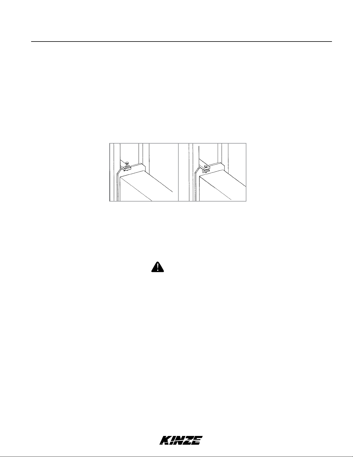
ROW MARKER LOCKUPS (CONVENTIONAL ROW MARKERS ONLY)
When lockups are not in use, store lockup pin in raised position with hair pin clip on upper side of tab. Install marker
lockups when transporting the planter or working around the planter.
Pin Stored In Raised
Position For Marker
Operation
Row Marker Locked
Up For Transport Or
Working Around The
Machine
WARNING
Row marker can lower at any time and could cause death or serious
injury. Stay away from row markers! Install safety lockup device when
not in use.
9/12 2-1
TM

Machine Operation
Model 3110M0244-01
INITIAL PREPARATION
Following information is general in nature to aid in preparation of tractor and planter for use, and to provide general
operating procedures. Operator experience, familiarity with the machine, and the following information should combine
for efficient planter operation and good working habits.
Lubricate the planter and row units per the lubrication information in this manual. Make sure all tires have been properly
inflated. See “Tire Pressure”. Check all drive chains for proper tension, alignment and lubrication.
Improperly operating or working on this equipment could result in
death or serious injury. Read and follow all instructions in Operator
Manual before operating or working on this equipment.
WARNING
WARNING
Loose transport wheel lug bolts can result in wheel separation
from planter and cause death, serious injury, and damage to
property and equipment. Torque transport wheel "- 18 lug bolts
to 90 ft-lb (122 N-m) before operating planter for the first time and
periodically after.
WARNING
Explosive separation of rim and tire parts can cause death or serious
injury.Overination,rimandtireservicing,improperuseofrimsandtires,
worn, or improperly maintained tires could result in a tire explosion.
1. Torque transport wheel "- 18 lug bolts to 90 ft-lb (122 N-m).
2. Inflate transport/ground drive tires to 40 psi (275.7 kPa).
Contact drive
3. Inflate contact drive tires to 50 psi (344.7 kPa).
Transport/ground drive
9/12 2-2
TM

Machine Operation
Model 3110M0244-01
TRACTOR REQUIREMENTS
Approximate required minimum tractor horsepower (HP) required for field work is listed below:
Row Sizes Horsepower
6 Row 55 - 85 HP
8 Row 75 - 110 HP
NOTE: The tractor must have adequate 3 point hitch lift capacity to lift the weight of the machine, attachments,
seed and dry chemicals. Shipping weights do not include seed, dry chemicals or additional optional attachments.
Tractor front end stability is necessary for safe efficient operation. Therefore, it may be necessary to add front ballast to
your tractor for satisfactory field operation, as well as adequate transport stability. Refer to your tractor operator’s manual
for front ballast recommendations.
A quick-attaching coupler (quick hitch) is recommended for safe and easy attaching and detaching.
A 12 volt DC electrical system is required for operate planter safety/warning lights, digital vacuum gauge.
One SCV remote hydraulic outlet is required to operate optional row markers and one SCV plus a zero pressure case
drain is required to operate the seed metering system vacuum fan.
Maximum hydraulic flow rate of 13 GPM @ 2000 PSI is required to operate the vacuum fan motor.
IMPORTANT: Connect hydraulic motor case drain to a case drain return line with zero PSI on the tractor. Failure
to connect to a return with zero PSI will cause damage to the hydraulic motor shaft seal. Warranty will not apply
on damaged motors resulting from improper hydraulic line connection. DO NOT connect hydraulic motor case
drain to a SCV outlet or motor return circuit connection. Contact tractor manufacturer for specific details on
“zero pressure return”.
9/12 2-3
TM
Machine Operation
M0244-01Model 3110
TRACTOR PREPARATION AND HOOKUP
1. Set tractor rear wheel spacing at double the planter row spacing. For example: On a planter set for 36" rows, set
the tractor wheel spacing at 72" center-to-center. On wide front end tractors set front wheel spacing equal to rear
wheel spacing. Check tractor operator’s manual for correct front and rear tire pressure.
2. Adjust lift links on tractor so planter will lift level from side to side and raise high enough for planter transport
clearance. Set the sway blocks on the tractor in position to prevent side sway. Be sure the individual lift link arms
are in the float position.
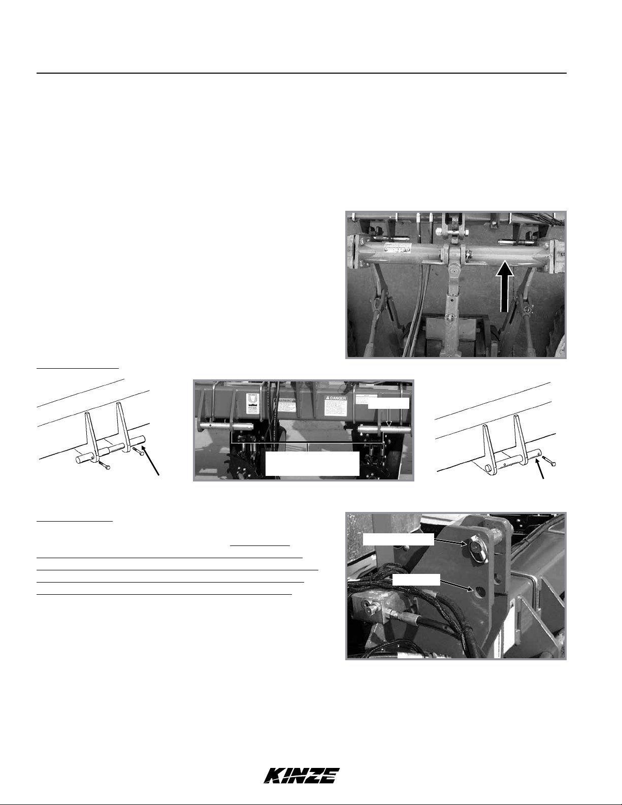
3. Back tractor up to planter. Position lower hitch pins and
bushings as shown in the following diagrams for your type
of tractor hitch. Line up holes and insert hitch pins and lock
in place with pins provided. It may be necessary to change
the length of the tractor upper link with the adjusting
handle.
NOTE: When using a quick-attaching coupler (customer supplied),
match pin location to pin spacing in quick-attaching coupler.
Lower Hitch Pins
32" - Category 2 & 3N
38" - Category 3
Category 2 Bushing Position
Category 2 Requires Pin Only
Category 3 And 3N Requires Pin And Bushing
Upper Hitch Pin
The upper hitch point has two sets of holes. The hitch pin
must be positioned in lower set of holes for use with tractors
equipped with Category 2 quick-attaching coupler. The hitch pin
must be positioned in upper set of holes for use with tractors
equipped with Category 3N and 3 quick-attaching coupler.
NOTE: Always use top hole when not using quickattaching coupler.
Bushing
Category 3 And 3N
Bushing Position
Category 3N & 3
Category 2
Connect ASAE Standards 7 terminal connector for safety/warning lights on planter to ASAE Standards receptacle on
4.
tractor. If your tractor is not equipped with an ASAE Standards receptacle, check with your tractor manufacturer for
availability. Check to be sure safety/warning lights on planter are working in conjunction with safety/warning lights on
tractor.
Connect harness on planter to digital vacuum gauge console on tractor. Connect power lead to power source. A
power lead adapter may be required.
2-4 9/12
TM
Machine Operation
Model 3110M0244-01
5. Connect hydraulic hoses to tractor ports in a sequence familiar and comfortable to the operator.
Before attaching hoses, move tractor control levers back and forth to relieve any pressure in the tractor hydraulic system.
WARNING
Pressurized hydraulic uid can penetrate body tissue and result
in death, serious infection, or other injuries. Fluid injected under
skin must be IMMEDIATELY removed by a surgeon familiar with this
type of injury. Make sure connections are tight and hoses and
fittings are not damaged before applying system pressure. Leaks
can be invisible. Keep away from suspected leaks. Relieve pressure
before searching for leaks or performing any system maintenance.
NOTICE
Wipe hose ends to remove any dirt before connecting couplers to
tractor ports or contamination may cause equipment failure.
NOTICE
EdgeVac fan motor hydraulic hoses and case drain must
be installed correctly. Motor can be damaged or equipment
will not operate properly.
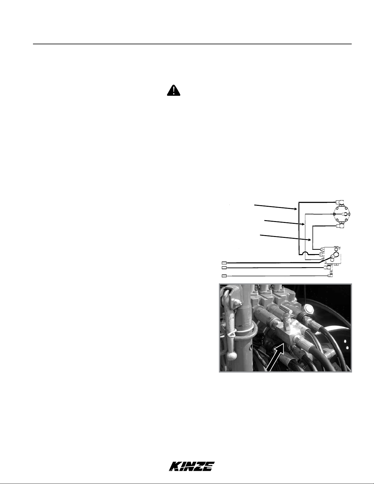
The vacuum fan motor operation hydraulic hoses are as
Return
Case Drain
Pressure
follows:
" hose from motor - Case Drain (CD - Orange or CD - Green)
¾" hose from motor - Return
½" hose to motor - Pressure
NOTE:AFlowControlNeedleValveKit,toprovideaow
control option for tractors that are not equipped with a
methodforneadjustmentofhydraulicow,isavailable
from Kinze Repair Parts through your Kinze Dealer.
G1K426 Needle Valve Kit
6. Raise planter slowly and watch for any interference. Remove pin from each parking stand and raise each to the
transport position. Secure stands in raised position with pin in lowest hole.
7. For proper operation of the planter and row units, it is important that the planter frame and row unit parallel arms
be level side-to-side and front-to-rear. The toolbar should operate at a 20"-22" height from planting surface. Tire
pressure must be maintained at pressures specified and toolbar height must be adjusted equally. Check to be sure
planter toolbar is level and at correct operating height. See “Leveling The Planter”.
NOTE: As a general safety practice and to avoid damage to the tractor hydraulic system, always lower the
planter when not in use.
9/12 2-5
TM
LEVELING THE PLANTER
1. Drive the tractor and planter on level ground.
2. Lower the planter to the ground.
Machine Operation
M0244-01Model 3110
3. Check to be sure toolbar height is 20"-22". See “Toolbar
Height Adjustment”.
4. Check to be sure planter is level front-to-rear and row
unit parallel arms are level. Adjust upper link on tractor
accordingly.
TOOLBAR HEIGHT ADJUSTMENT
Toolbar
Level
Planting
20"-22"
Surface
Upper Link
Shown With Customer-Supplied Quick Hitch
Standard Rear Mounted Drive Wheel Optional Front Mounted Drive Wheel
The drive wheel assembly is designed so the wheel can be adjusted to maintain a toolbar height of 20"-22" from the
planting surface in all planting situations. This is particularly useful when the planter is used for ridge planting or planting
on beds. The drive wheel assembly has an adjustment range of 7".
To adjust toolbar height:
1. Loosen the jam nut using a 1½" wrench or a 15" adjustable wrench.
2. Turn the adjusting nut using a 1" wrench or 15" adjustable wrench (clockwise to decrease frame height or counter
clockwise to increase frame height).
3. Tighten the jam nut.
2-6 9/12
TM

Machine Operation
Model 3110M0244-01
PARKING STAND ADJUSTMENT
Two parking stands, located on front side of main frame, are standard on all Model 3110 planters. The stands must be
positioned so they are not directly behind tractor tire or they will hit when planter is raised.
Raise to top position and pin when planting. Lower and pin for parking and storage.
On planters equipped with front mounted drive wheels, parking stands are not required.
Each parking stand has six positioning holes. By using these positioning holes, you can set toolbar height from 19" to 25".
9/12 2-7
TM
Machine Operation
M0244-01Model 3110
SEED RATE TRANSMISSION ADJUSTMENT
Planting population rate changes are made at the seed rate transmissions. The seed rate transmissions are designed
to allow simple, rapid changes of sprockets to obtain the desired planting population. By removing lynch pins on
hexagon shafts, sprockets can be interchanged with those from the sprocket storage rod bolted to each transmission.
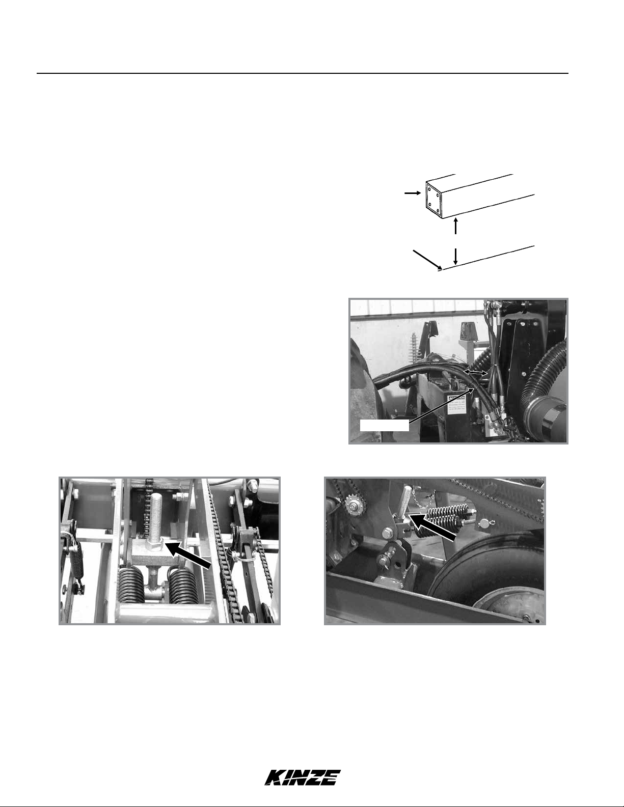
Chain tension is controlled by a spring-loaded, dual-sprocket idler. The idler assembly is adjusted with an easy-release
idler arm. This arm has a release position to remove spring tension for replacing sprockets. The amount of spring
tension on chain is controlled by idler arm. See “Wrap Spring Wrench Operation”.
A decal positioned near each transmission illustrates proper chain routing. The planting rate charts found in the Rate
Charts section will aid you in selecting correct sprocket combinations.
CONTACT WHEEL DRIVE SPROCKETS
Drive Sprocket
NOTE: 15 tooth, 19 tooth or 30 tooth drive sprockets at each contact drive wheel can be interchanged from the
sprocket storage rod bolted to each transmission. The 15 and 19 tooth sprockets require use of a 218 pitch No.
40 chain. The 30 tooth sprocket requires use of a 224 pitch No. 40 chain.
Chain tension is controlled by a spring-loaded sprocket idler. The amount of spring tension on the chain is controlled by
the idler arm.
The planting rate charts found in the Rate Chart section will aid you in selecting the correct sprocket.
NOTE: 15, 19, and 30 tooth drive sprockets are NOT applicable to all rate charts. Check chart titles to ensure
the proper rate chart is selected.
NOTE: After each sprocket combination adjustment, make a field test to be sure you are planting at the desired rate.
2-8 9/12
TM
Machine Operation
CONTACT WHEEL SPRING ADJUSTMENT
Model 3110M0244-01
There are two down pressure springs on each contact drive
wheel. The spring tension is factory preset and should need
no further adjustment.
The tension is set leaving 1" between the spring plug and the
mounting shaft as shown below.
SHEAR PROTECTION
The planter driveline and seed and granular chemical drivelines
are protected from damage by shear pins.
If excessive load should cause a pin to shear, it is important to
determine where binding has occurred before replacing the pin.
Replace shear pins with same size and type.
To prevent future binding or breakage of components, check
driveline alignment and follow prescribed lubrication schedules.
WRAP SPRING WRENCH
1"
/" Shear Pin
Transmission Shaft
Chain idlers use wrap spring wrenches to release and adjust transmission chain tension.
NOTE: Wrap spring wrenches are L.H. and R.H. specific. L.H. styles have silver metal or grey plastic release
collars. R.H. styles have gold metal or blue plastic release collars.
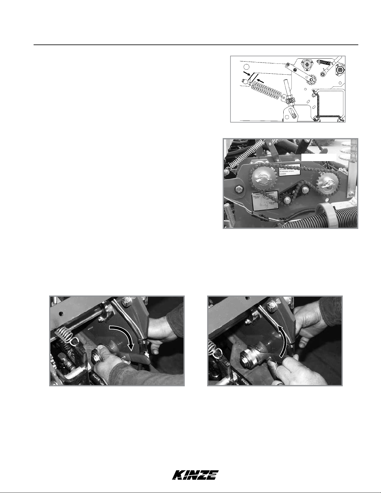
To add chain tension, rotate the chain idler into
the chain while rotating the handle to tension
idler spring.
Rotate wrap spring wrench knurled collar while rotating chain idler away from chain to release chain tension.
Rotate chain idler into chain while rotating handle to tension idler spring.
The wrap spring wrenches are made in L.H. and
R.H. configurations, which can be identified by
the silver or gold release collars, respectively.
9/12 2-9
TM

Machine Operation
M0244-01Model 3110
EDGEVAC SYSTEM
Kinze EdgeVac seed metering system includes seed meters, seed discs, and an air system consisting of a hydraulic
driven vacuum fan which draws air through manifolds, hoses, and seed meters on each row unit.
WARNING
Moving fan blades can cause amputation or severe injury. Never
operate vacuum fan with cover removed.
DIGITAL VACUUM GAUGE OPERATION
Digital vacuum gauge
The digital vacuum gauge console controls EdgeVac vacuum fan. Use “FAN 1” setting when planter is equipped with
one vacuum fan.
NOTE: Toggle switch must be OFF when planter is not in use or tractor battery will drain.
The digital vacuum gauge is factory calibrated. However, vacuum varies throughout the manifold system and it may be
necessary to adjust the digital readout so it agrees with actual vacuum at the meter. With the seed discs loaded with
seed, compare digital vacuum gauge readout to reading taken from analog gauge or a hand held gauge at several
meters along length of planter.
Elbows at seed meter covers allow testing of meter vacuum levels without removing vacuum hoses. If there is more
than 1" or 2" (H2O) difference, adjust gauge by inserting a small flat bladed screwdriver into opening on back of digital
gauge housing and turning potentiometer until digital gauge displays meter vacuum reading.
Compare readings at 10" and 20" of vacuum.
ANALOG VACUUM GAUGE
The analog vacuum gauge connects directly to the manifold or
is teed into the digital sending unit on newer models.
Only gauge adjustment is to “zero” needle with no vacuum
present. If there is a significant difference between this gauge
and a reading taken at meters, a different manifold location
should be found to connect hose to gauge and digital sending
unit.
Analog vacuum gauge
2-10 9/12
TM
Machine Operation
Model 3110M0244-01
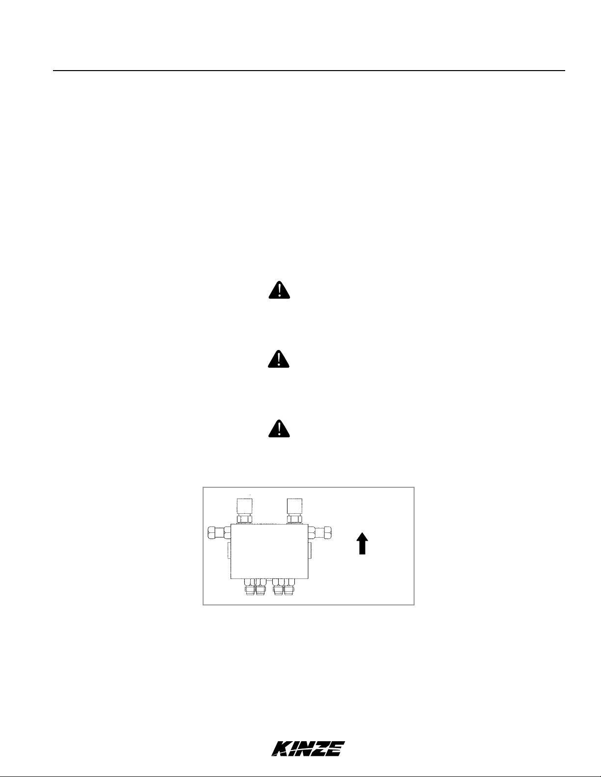
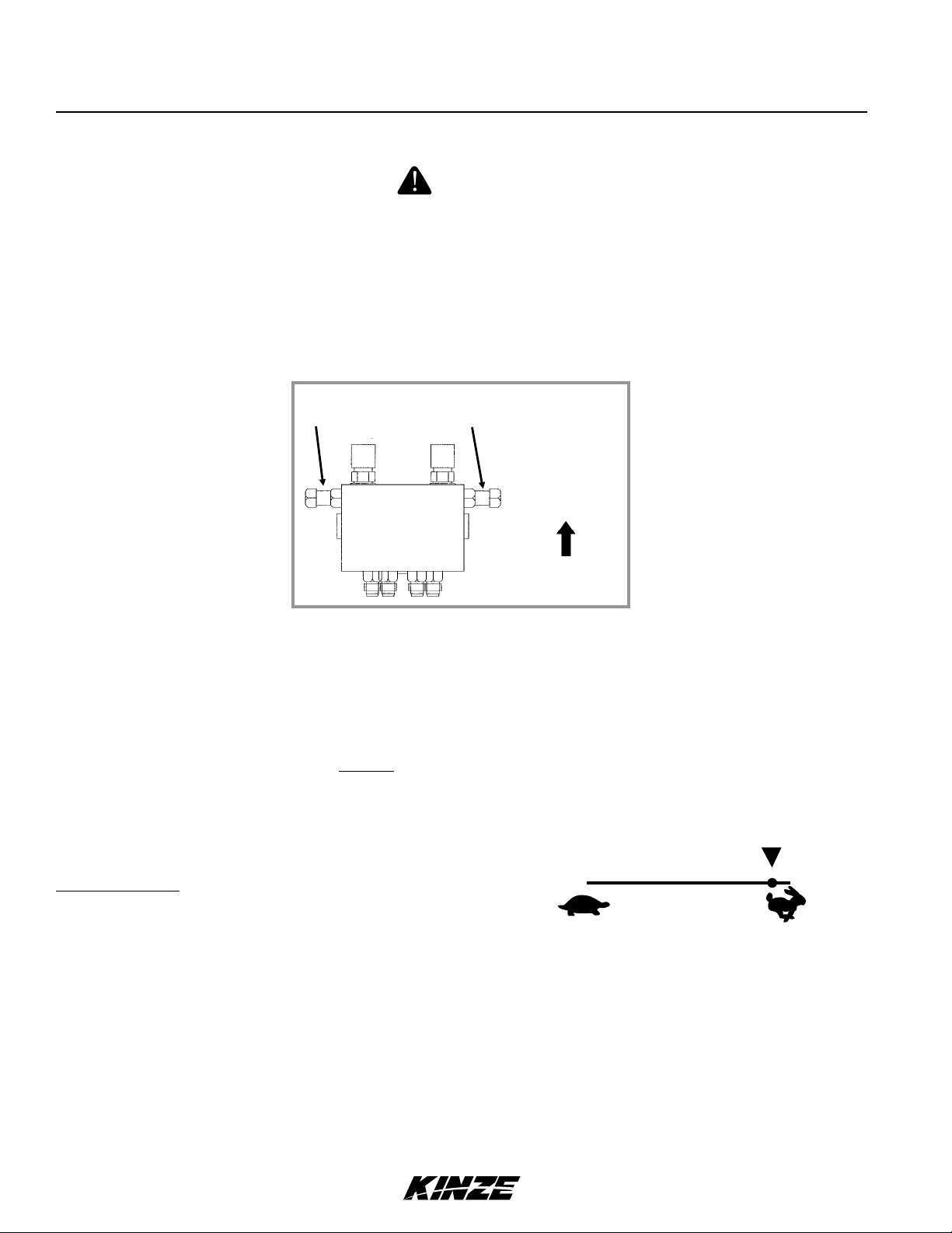
VACUUM FAN MOTOR VALVE BLOCK ASSEMBLY
A pressure relief valve in the hydraulic circuit prevents build up of oil pressure over 35 PSI in case drain line when
vacuum fan motor is operating. This valve will vent oil outside valve block through a drain hole in the aluminum valve
block. This can occur whenever case drain is improperly connected or pressure in motor circuit builds.
See “Hydraulic Diagram - Vacuum Fan Motor System” in Lubrication and Maintenance section.
Valve block contains a check valve that prevents vacuum fan from operating in wrong direction if pressure is applied to
return side of motor and allows fan to coast to a stop when tractor hydraulic control is returned to neutral position.
NOTE: Fan turns at a reduced speed If reverse pressure is applied.
ROW MARKER OPERATION
The machine is equipped with a single control valve system for the optional row markers.
DANGER!
Contacting or coming close to power lines or other high energy
sources will cause death or serious injury. Keep away from power
lines or high energy sources at all times.
WARNING
Uncontrolled movement of equipment can cause loss of control
and could result in death, serious injury, or damage to property and
equipment. Install all safety pins before transporting equipment.
WARNING
Row marker can lower at any time and could cause death or serious
injury. Stay away from row markers! Install safety lockup device when
not in use.
DIRECTION
OF TRAVEL
Sequencing/Flow Control Valve Used With Single
Valve Row Marker Hydraulic System
The single valve marker system uses a sequencing valve which directs hydraulic flow to operate the markers alternately.
With the single valve marker system, both markers can be used at the same time by first lowering one marker and moving
the hydraulic control to the raise position and immediately returning it to the lower position. This will shift the marker
control valve spool and the opposite marker will be lowered.
NOTE: If a marker cylinder has been disconnected or removed for any reason, do not attach the rod end of the
cylinder until the cylinder is cycled several times to remove any air that may be trapped in the system.
9/12 2-11
TM
Machine Operation
M0244-01Model 3110
ROW MARKER SPEED ADJUSTMENT
DANGER!
Contacting or coming close to power lines or other high energy
sources will cause death or serious injury. Keep away from power
lines or high energy sources at all times.
The marker hydraulic system includes two flow control valves. One flow control valve sets the lowering speed of both
markers and one sets the raising speed of both markers. To adjust marker speed, loosen the jam nut and turn the
control(s) clockwise or IN to slow the travel speed and counterclockwise or OUT to increase the travel speed. The
flow control(s) determines the amount of oil flow restriction through the valve(s), therefore varying travel speed of the
markers. Tighten jam nut after adjustments are complete.
Flow Control
Marker Raise
Sequencing/Flow Control Valve Used With Single
Valve Row Marker Hydraulic System
Flow Control
Marker Lower
DIRECTION
OF TRAVEL
IMPORTANT:Theowcontrolsshouldbeproperlyadjustedbeforethemarkerassemblyisrstputintouse.
Excessive travel speed of the markers can damage the marker assembly.
NOTE: When oil is cold, hydraulics operate slowly. Make sure all adjustments are made with warm oil.
NOTE:Onatractorwheretheoilowcan notbecontrolled,therateofowofoilfromthetractormaybe
greater than the rate at which the marker cylinder can accept the oil. The tractor hydraulic control will have to
be held until the cylinder reaches the end of its stroke. This occurs most often on tractors with open center
hydraulic systems.
On tractors with closed center hydraulic systems, the
tractor'shydraulicowcontrolshouldbeadjustedtothe
fullowposition. If oil is restricted, the sequencing valve
may not shift properly.
2-12 9/12
TM
Machine Operation
ROW MARKER ADJUSTMENTS
1. Multiply number of rows by the average row spacing in inches to determine total planting width.
Model 3110M0244-01
Row Marker Lengths
6 Row 30" 180" (457.2 cm)
6 Row 36" 216" (548.64 cm)
6 Row 40" 240" (609.6 cm)
8 Row 30" 240" (609.6 cm)
8 Row 36" 288" (731.52 cm)
8 Row 40" 320" (812.8 cm)
2. Lower planter and row marker assembly to ground.
3. Measure from planter center line to a point where blade contacts ground.
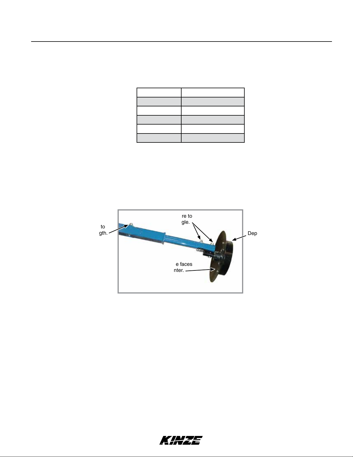
4. Adjust row marker extension so distance from marker disc blade to center line of planter is equal to total planting
width. Adjust right and left row marker assemblies equally and securely tighten clamping bolts.
Loosen hardware to
Loosen hardware to
adjust marker length.
adjust blade angle.
Depth band
Concave side faces
towards planter.
Row marker disc blade angle adjustment
NOTICE
Setting marker disc blade assembly at a sharper angle than needed
adds stress to row marker assembly and shortens bearing and
blade life. Set blade angle only as needed to leave a clear mark.
Marker disc blade is installed with concave side facing inward. Spindle assembly is slotted so hub and blade can be
angled to throw more or less dirt.
5. Loosen hardware and move assembly as required.
6. Tighten bolts to specified torque.
7. Do a field test to ensure markers are properly adjusted.
NOTE: A notched marker blade is available from Kinze through your Kinze Dealer for use in more severe no
till conditions.
9/12 2-13
TM
Machine Operation
M0244-01Model 3110
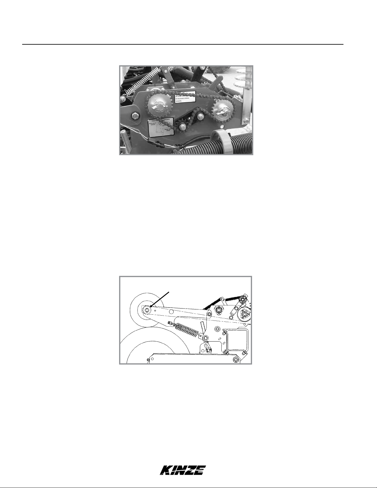
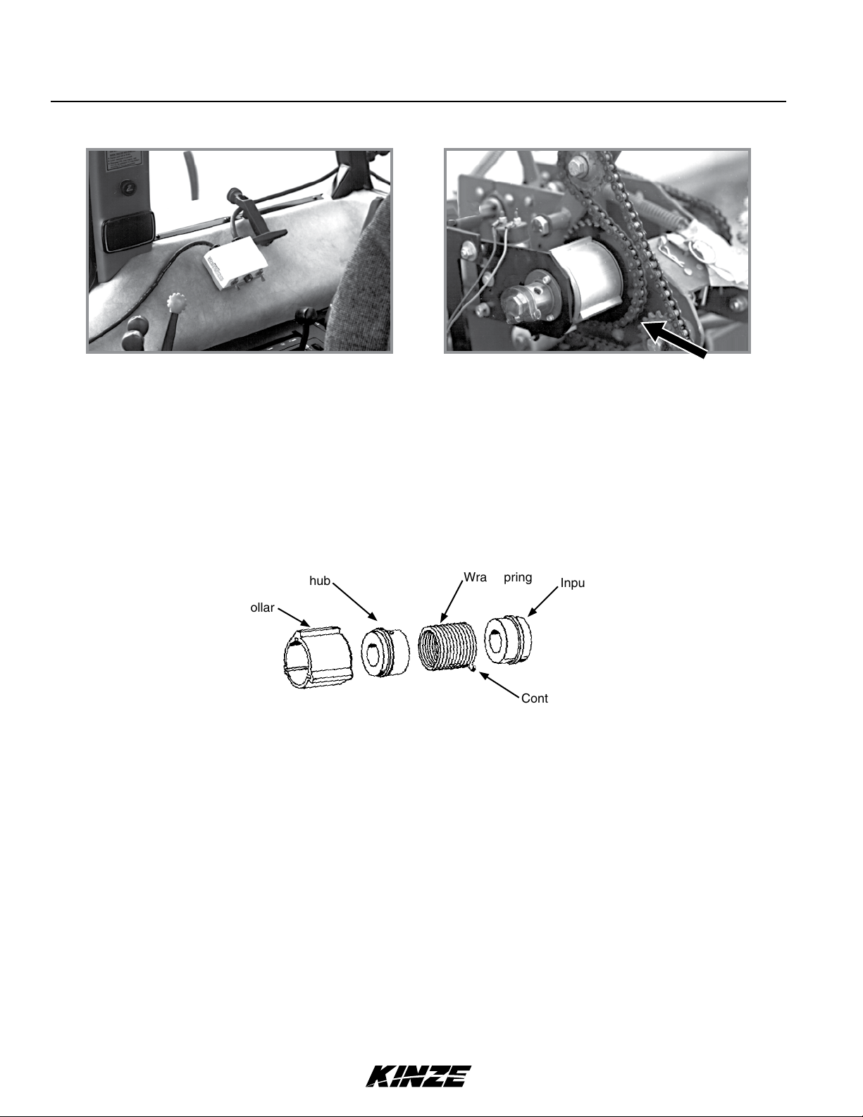
POINT ROW CLUTCHES
L.H. Side Of Planter ShownPoint Row Clutch Control Box
Electric-activated clutches disengage drive on either half of planter for finishing up fields or for long point row
situations. Clutch selector switch is located on tractor control box.
NOTICE
Switch must be OFF when planter is not in use or tractor battery
will be drained.
NOTE: Liquid fertilizer piston pump has its own drive wheel and is not affected by point row clutch.
Output hub
Stop collar
Wrap spring
Input hub
Control tang
Clutch consists of a wrap spring riding on an input and output hub. Wrap spring is wrapped tightly over hubs during
operation locking them together. Higher speeds create a tighter grip of spring on hubs.
Input end of spring is bent outward and is called the control tang. Control tang fits into a slot in stop collar located
between input and output hubs over wrap spring. If stop collar is allowed to rotate with input hub, clutch is engaged. If
stop collar is stopped from rotating, control tang connected to it is forced back and spring opens. This allows input hub
to continue rotating without transmitting torque to output hub, stopping planter drive.
Stop collar is controlled by an electric solenoid and an actuator arm. When selector switch on tractor control box is
OFF, solenoid coil is NOT ENERGIZED and actuator arm will not contact stop on stop collar, allowing it to rotate with
hubs and drive planter.
When operational switch is in “DISENGAGE” (right or left) solenoid coil IS ENERGIZED and plunger in solenoid coil
pulls actuator arm against stop on stop collar, disengaging wrap spring and stopping planter drive.
2-14 9/12
TM

Machine Operation
Model 3110M0244-01
FRONT MOUNTED DRIVE WHEEL OPTION
R.H. Side Of Planter Shown
An optional Front Mounted Drive Wheel Conversion Package is available if front-mounted drive wheels are desired.
PLANTING SPEED
Planters are designed to operate within a speed range of 2 to 8 mph (3.2 - 12.8 kph). See “Rate Charts”. Variations in
ground speed produce variations in rates. Finger pickup seed meter populations tend to be disproportionately higher at
high ground speeds.
NOTE: Seed spacing can be adversely affected at speeds above 5.5 mph (8.8 kph).
FIELD TEST
Perform a field test with any change of field and/or planting conditions, seed size or planter adjustment to ensure
proper seed placement and operation of row units. See “Rate Charts”, “Checking Seed Population” and “Checking
Granular Chemical Application Rate”.
Check planter for front to rear and lateral level operation. See “Level Planter”.
Check all row units to be certain they are running level. Row unit parallel arms should be approximately parallel to
the ground when planting.
Check row markers for proper operation and adjustment. See “Row Marker Adjustment” and “Row Marker Speed
Adjustment”.
Check for proper application rates and placement of granular chemicals on all rows. See “Checking Granular
Chemical Application Field Check”.
Check for desired depth placement and seed population on all rows. See “Check Seed Population”.
Check for proper application rates of fertilizer on all rows. See proper “Fertilizer Application Rate Chart”.
Reinspect machine after field testing.
Hoses And Fittings
Bolts And Nuts
Cotter Pins And Spring Pins
Drive Chain Alignment
9/12 2-15
TM
Machine Operation
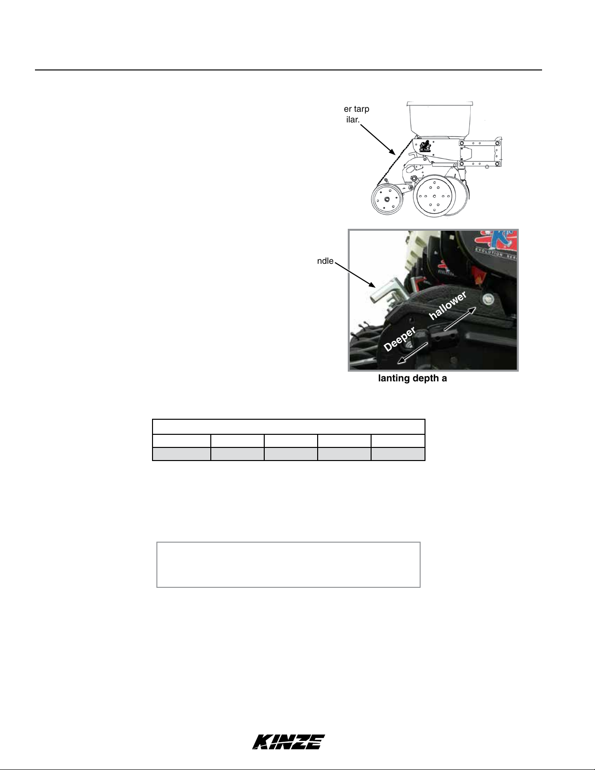
CHECK SEED POPULATION
1. Tie up one or more sets of closing wheels by running a
chain or rubber tarp strap between the hopper support
panel and closing wheels. It may be necessary to decrease
closing wheel arm spring tension.
Planting depth
adjustment handle
2. Plant a short distance and check to see if seed is visible in
the seed trench. Adjust planting depth to a shallower setting
if seed is not visible and recheck.
M0244-01Model 3110
Chain, rubber tarp
strap, or similar.
Deeper Shallower
Planting depth adjustment
3. Measure of an acre. See chart for correct distance for row width being planted. For example, if planting 30"
rows of an acre would be 17' 5".
Acre Seed Population Count Row Width/Distance
Row Width 30" 36" 38" 40"
Distance 17'5" 14'6" 13'10" 13' 1"
NOTE: Seeds may bounce or roll when planting with closing wheels raised and planting depth set shallow
affecting seed spacing accuracy.
4. Count seeds in measured distance.
5. Multiply number of seeds placed in of an acre by 1000. This gives total population.
Seed count can be affected by drive wheel and seed meter drive ratio, tire pressure, and/or seed meter malfunction.
1. If seed check shows average distance between seeds in inches is significantly different than seed rate chart
indicates, first check drive ratio between drive wheel and seed meter. Check drive wheel air pressure, check for
incorrect sprocket(s) in driveline and check drive and driven sprockets on transmission(s) for proper selection.
EXAMPLE: 30" row spacing 17' 5" equals acre.
26 seeds counted x 1000 = 26,000 seeds per acre
2. Check for seed meter malfunction. For example, if spacing between kernels of corn at the transmission setting
being used is 8" and a gap of 16" is observed, a finger has lost its seed and not functioned properly. If two seeds
are found within a short distance of each other, the finger has metered two seeds instead of one.
3. See “Finger Pickup Seed Meter” and/or “Brush-Type Seed Meter” in the Troubleshooting Section of this manual.
2-16 9/12
TM

Machine Operation
Model 3110M0244-01
DETERMINING POUNDS PER ACRE (BRUSH-TYPE METER)
Seeds per acre ÷ Seeds per pound (from label) = Pounds per acre
If seeds per pound information is not available use the following averages:
2,600 seeds per pound for medium size soybeans
15,000 seeds per pound for medium size milo/grain sorghum
4,500 seeds per pound for medium size cotton
DETERMINING BUSHELS PER ACRE
Pounds per acre ÷ Seed unit weight = Bushels per acre
Average Unit Weight of:
1 Bushel Soybeans = 60 Pounds
1 Bushel Milo/Grain Sorghum = 56 Pounds
1 Bushel Cotton = 32 Pounds
If seed population check shows planting rate is significantly different than seed rate chart shows or if a particular
meter is not planting accurately, see “Brush-Type Seed Meter Maintenance” and “Brush-Type Seed Meter
Troubleshooting”.
9/12 2-17
TM

Machine Operation
M0244-01Model 3110
FIELD CHECK GRANULAR CHEMICAL APPLICATION
Temperature, humidity, speed, ground conditions, flowability of different material, or meter obstructions can affect
granular chemical rate of delivery.
WARNING
Agricultural chemicals can cause death or serious injury to persons,
animals, and plants or seriously damage soil, equipment, or property.
Read and follow all chemical and equipment manufacturers labels
and instructions.
Perform a field check to determine application rates.
Calibrated vial
Granular chemical field check
1. Fill insecticide and/or herbicide hoppers.
2. Attach a calibrated vial to each granular chemical meter.
NOTE: Disengage clutch to avoid dropping seed during test.
3. Lower planter and drive 1320 feet at planting speed.
4. Weigh chemical in ounces caught in one vial.
5. Multiply that amount by factor shown to determine pounds per acre.
Pounds Per Acre
Row Width Factor
30" .83
36" .69
38" .65
EXAMPLE: You are planting 30" rows. You have planted for 1320 feet at desired planting speed. You caught 12.0
ounces of chemical in one vial. 12.0 ounces times 0.83 equals 9.96 pounds per acre.
NOTE: Check calibration of all rows.
METERING GATE
Use metering gate setting as a starting point for distributing insecticide or herbicide. Charts are based on 5 mph
(8 kph) planting speed. Use a higher gate setting for speeds faster than 5 mph (8 kph) and a lower setting for speeds
slower than 5 mph (8 kph).
2-18 9/12
TM
 Loading...