

Kinze 3000 User Manual

OPERATOR MANUAL
M0246
KINZE ISOBUS ELECTRONICS PACKAGE
FOR 3000 SERIES PLANTERS
Rev. 5/14


KINZE ISOBUS ELECTRONICS PACKAGE
FOR 3000 SERIES PLANTERS
OPERATOR
MANUAL
M0246 Rev. 5/14
This manual is applicable to: Kinze ISOBUS Planter Monitoring/Control System
Firmware Version: 2.0
Record the serial numbers of your planter control system and the purchase date:
Planter Monitor Module Serial Number _____________________________
Planter Control Module Serial Number _____________________________
Date Purchased _______________________________________________
Measured Pulses Per Mile
(Planter Seed Sensor) __________________________________________
Kinze®, the Kinze® logo, Twin-Line®, Interplant®, and EdgeVac®
are trademarks owned by Kinze Manufacturing, Inc.
John Deere® is a trademark of Deere and Co.

This page left blank intentionally.

Table of Contents
ISOBUSM0246
OVERVIEW
To The Owner ........................1
Warranty ............................2
Introduction ..........................3
Specifications. . . . . . . . . . . . . . . . . . . . . . . . .4
SYSTEM OVERVIEW
ISOBUS System ......................5
CAN-Bus Technology ...................5
9-Pin Connector .......................5
ISOBUS Diagram. . . . . . . . . . . . . . . . . . . . . .6
Home Screen. . . . . . . . . . . . . . . . . . . . . . . . .7
PLANTER CONFIGURATION
Configuration Wizard ...................9
Sensor Programming ..................11
PLANTING SETUP
Custom Crop ........................13
Crop Selection Screen. . . . . . . . . . . . . . . . .13
Set Population Screens . . . . . . . . . . . . . . . .14
Edit Presets . . . . . . . . . . . . . . . . . . . . . . . . .14
Basic Population .....................15
Halves Population ....................15
Prescription Population ................16
Software Update .....................17
Area . . . . . . . . . . . . . . . . . . . . . . . . . . . . . . .18
Page Layout Screen. . . . . . . . . . . . . . . . . . .19
Plant Screens .......................20
SETTINGS
Advanced Settings. . . . . . . . . . . . . . . . . . . .36
Bulk Fill Pressure. . . . . . . . . . . . . . . . . . . . .33
Bulk Fill Scale .......................34
Diagnostics .........................37
MUXBUS ...........................35
Pneumatic Down Force (PDP). . . . . . . . . . .31
Population Monitoring .................32
Section Control Diagnostics. . . . . . . . . . . . .38
Seed Count Diagnostics ...............38
Seed Sensor Sensitivity (Seed Counter) . . .34
Settings Screen ......................29
Speed Input . . . . . . . . . . . . . . . . . . . . . . . . .29
Vacuum ............................33
OFFSETS AND LOOK AHEADS ....... 23
Offsets . . . . . . . . . . . . . . . . . . . . . . . . . . . . .23
Look-Aheads ........................24
ALARMS .......................... 27
Rev. 5/14 i
TM

This page left blank intentionally.
To The Owner
ISOBUSM0246
Kinze Manufacturing, Inc. thanks you for your patronage. We appreciate your confidence in Kinze farm machinery. Your
Kinze planter has been carefully designed to provide dependable operation in return for your investment.
This manual has been prepared to aid you in the operation and maintenance of the ISOBUS display. It should
be considered a permanent part of the machine and remain with the machine when you sell it.
It is the responsibility of the user to read and understand the Operator Manual in regards to safety, operation,
lubrication and maintenance before operation of this equipment. It is the user’s responsibility to inspect and service
the machine routinely as directed in the Operator Manual. We have attempted to cover all areas of safety, operation,
lubrication and maintenance; however, there may be times when special care must be taken to fit your conditions.
Throughout this manual the symbol and the words DANGER, WARNING, and CAUTION are used to call
attention to safety information that if not followed, will or could result in death or injury. NOTICE and NOTE are used to
call your attention to important information. The definition of each of these terms follows:
DANGER Indicates a hazardous situation which, if not avoided, will result in death or serious
injury.
WARNING Indicates a hazardous situation which, if not avoided, could result in death or serious
injury.
CAUTION, used with the safety alert symbol, indicates a hazardous situation which, if not avoided,
could result in minor or moderate injury.
NOTICE is used to address practices not related to personal injury.
NOTE: Special point of information or machine adjustment instructions.
WARNING
Improperly operating or working on this equipment could result in
death or serious injury. Read and follow all instructions in Operator
Manual before operating or working on this equipment.
WARNING
Some photos in this manual may show safety covers, shields, or
lockup devices removed for visual clarity. NEVER OPERATE OR
WORK ON machine without all safety covers, shields, and lockup
devices in place as required.
NOTE: Photos in this manual may be of prototype machines. Production machines may vary in
appearance.
NOTE: Some photos and illustrations in this manual show optional attachments installed. Contact
your Kinze Dealer for purchase of optional attachments.
Rev. 5/14 1
TM

Warranty
M0246ISOBUS
The Kinze Limited Warranty for your new machine is stated on the retail purchaser’s copy of the Warranty And Delivery
Receipt form. Additional copies of the Limited Warranty can be obtained through your Kinze Dealer.
Warranty, within the warranty period, is provided as part of Kinze’s support program for registered Kinze products
which have been operated and maintained as described in this manual. Evidence of equipment abuse or modification
beyond original factory specifications will void the warranty. Normal maintenance, service and repair is not covered by
Kinze warranty.
To register your Kinze product for warranty, a Warranty And Delivery Receipt form must be completed by the Kinze
Dealer and signed by the retail purchaser, with copies to the Dealer, and to the retail purchaser. Registration must be
completed and submitted to Kinze Manufacturing, Inc. within 5 business days of delivery of the Kinze product to the
retail purchaser. Kinze Manufacturing, Inc. reserves the right to refuse warranty on serial numbered products which
have not been properly registered.
If service or replacement of failed parts which are covered by the Limited Warranty are required, it is the user’s
responsibility to deliver the machine along with the retail purchaser’s copy of the Warranty And Delivery Receipt to
the Kinze Dealer for service. Kinze warranty does not include cost of travel time, mileage, hauling or labor. Any prior
arrangement made between the Dealer and the retail purchaser in which the Dealer agrees to absorb all or part of this
expense should be considered a courtesy to the retail purchaser.
Kinze warranty does not include cost of travel time, mileage, hauling, or labor.
2 Rev. 5/14
TM
Introduction
ISOBUSM0246
ISOBUS is an agricultural industry term used to describe software and hardware that complies with the global
ISO11783 standard. ISO11783 was created by an international standards committee of representatives from different
agricultural companies. The standard was created to allow plug-and-play compatibility between different manufacturers
of tractors, harvesters, sprayers, implements, and more.
There are 14 different parts to the ISO11783 standard. A device does not have to support all 14 parts to be
considered ISO compatible or certified. The parts that are important to the Kinze ISOBUS solution are the Virtual
Terminal (VT) and the Task Controller (TC).
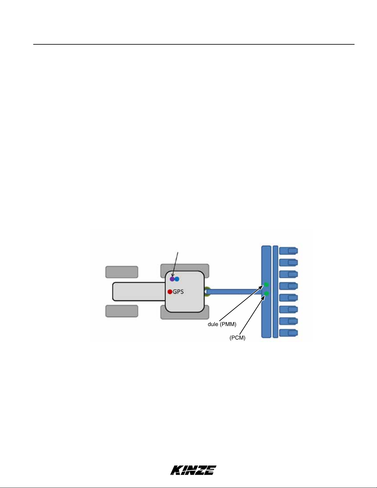
ISOBUS COMPONENTS
• Virtual Terminal (VT) - A display in the cab of the tractor. The operator interacts with the display to monitor
information and change settings.
• Task Controller (TC) - Makes automatic swath control, automatic rate control, and as-applied mapping possible.
The functionality is software based, so does not require a separate box. When present, it is normally built into the
display. Every ISOBUS display is a Virtual Terminal, but not every display has a task controller.
• Planter Monitor Module (PMM) - The brains of the system. This device is found on the planter and relays
information to and takes inputs from the VT. The PMM is part of the Kinze ISOBUS option.
• Planter Control Module (PCM) - Device on the planter that executes the manual and automatic rate control,
clutches and automatic clutch control, plus swath control commands. These functions are available with the Kinze
ISOBUS product control package.
Virtual Terminal Display
with Task Controller
Planter Monitor Module (PMM)
Planter Control Module (PCM)
GENERAL INFORMATION
The information used in this manual was current at the time of printing. However, due to Kinze’s ongoing product
improvement, production changes may cause your planter control system display to appear or operate slightly
different in detail. Kinze Manufacturing, Inc. reserves the right to change specifications or design without notice and
without incurring obligation to install the same on machines previously manufactured.
Right hand (R.H.) and left hand (L.H.), as used throughout this manual, are determined by facing in the direction the
machine will travel when in use, unless otherwise stated.
Rev. 5/14 3
TM

Specifications
KINZE ISOBUS PLANTER CONTROL SYSTEM DISPLAY
Absolute Voltage Range .......................................................... 0 to 60v
Connector ..............................................................(1) 9-Pin Deutsch
Environmental Operating Temperature ............................................14˚ to 149˚F
Full Function Voltage Range .......................................................8 to 18v
Input/Output ...............................................................CAN, Muxbus
Maximum Current Draw ............................................................. 20A
Operating Voltage Range ......................................................... 6 to 19v
Power Loss Protection for Shutdown ....................................................Yes
Reverse Voltage Protection ...........................................................Ye s
Storage Temperature ........................................................ -22˚ to 158˚F
M0246ISOBUS
4 Rev. 5/14
TM

System Overview
ISOBUSM0246
ISOBUS SYSTEM
ISOBUS provides a consistent user interface for planter functionality, regardless of the tractor brand that is pulling the
implement. The ISOBUS control system plugs into a compatible, existing monitor in the cab of the tractor. The existing
monitor becomes a Virtual Terminal (VT) for Kinze controls and monitoring.
CAN-BUS TECHNOLOGY
The ISOBUS system uses Controller Area Network (CAN) technology. CAN systems are comprised of individual
modules, each with their own high speed processor, connected through a high-speed communications cable. CAN
has many benefits, including greater ability to configure and expand the system, compatibility, simpler installs with less
wiring and increased system dependability.
9-PIN CONNECTOR
The 9-Pin round pin connector contains CAN, ECU power, solenoid power, and grounds .
NOTE: The displays used in this manual are from a John Deere virtual terminal. Your
virtual terminal may vary slightly depending on the manufacturer.
Rev. 5/14 5
TM

ISOBUS DIAGRAM
TBC
ISOBUS (Tractor) Connection
Fuse 10 AMP Fuse 20 AMP
PMM
Y-Splitter
System Overview
M0246ISOBUS
ISOBUS Harness
CAN Jumper
Cable
Product Control Module
Cable
PCM
Mux A
(Rear)
Sensor Harnesses (Varies By # of Rows)
NOTE: Sensors for ASD, EdgeVac, PDP, Scale
and Jump Start/Implement can plug into
Mux A or Mux B.
Mux B
(Front)
Clutch Cable
Clutch Adapter Cable
(Polarity Reversal Required)
Electric Clutches
2-Way Ter minating
Resistor
Jump Start Cable
Connects to
Sensor Harness
Hall Effect Adapter
Section Adapter Cable
Clutch
Control
Ground
Implement
Switch
Encoder
Control
1
Rate
2
Rate Control
Cable
3
Hydraulic
Motor
Jump Start
Sensor
6 Rev. 5/14
Implement Switch Extension Harness
TM
Implement
Switches
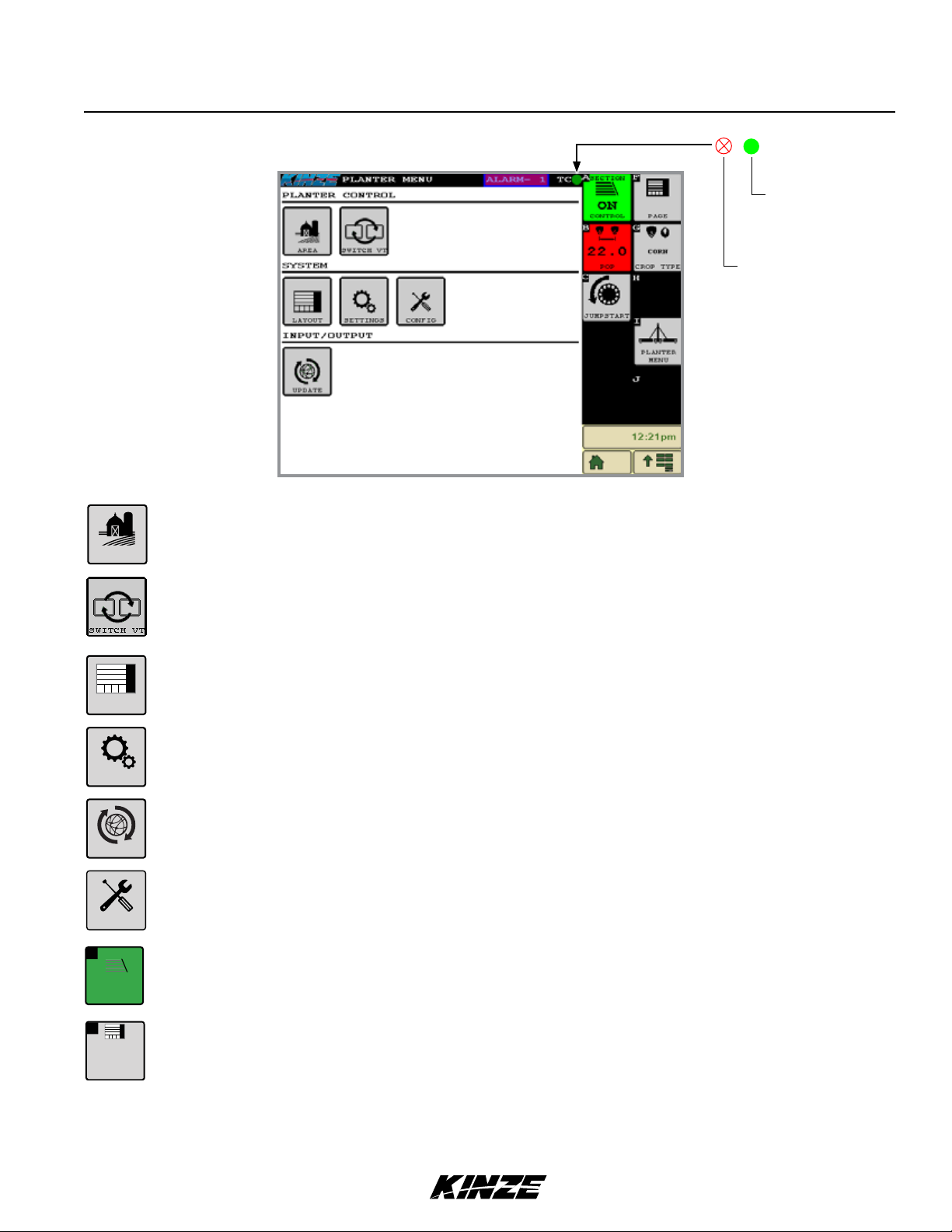
HOME SCREEN
Area opens window that displays multiple acre counters.
System Overview
Task Controller is in
full communication
with planter.
Task Controller is not
present.
ISOBUSM0246
AREA
LAYOUT
SETTING
UPDATE
CONFIG
SECTION
A
ON
CONTROL
Switch VT toggles between displays when more than one display is being used.
Layout button opens window to set the layout and visibility of the plant screens 1-6.
Settings button opens window that display Speed Input, Advance Seed Counter, Muxbus, Pneumatic
Downforce, Seed Sensor Sensitivity, Population Monitoring, Bulk Fill Pressure, Bulk Fill Scale, and
EdgeVac Pressure. For more information, see the Settings Section.
Update button opens window that displays upgrades that are available on a USB Drive.
Configuration button opens a wizard that steps through the configuration of the planter. For more
information, see the Configuration Section.
Section Control button will turn section control on or off from the planter. If turned off, use the manual
section buttons. Refer to page 20 for more information.
F
PAG E
1 OF 4
Rev. 5/14 7
Pages Tapping on the "Pages" button allows you to toggle through the plant screens and menu.
TM
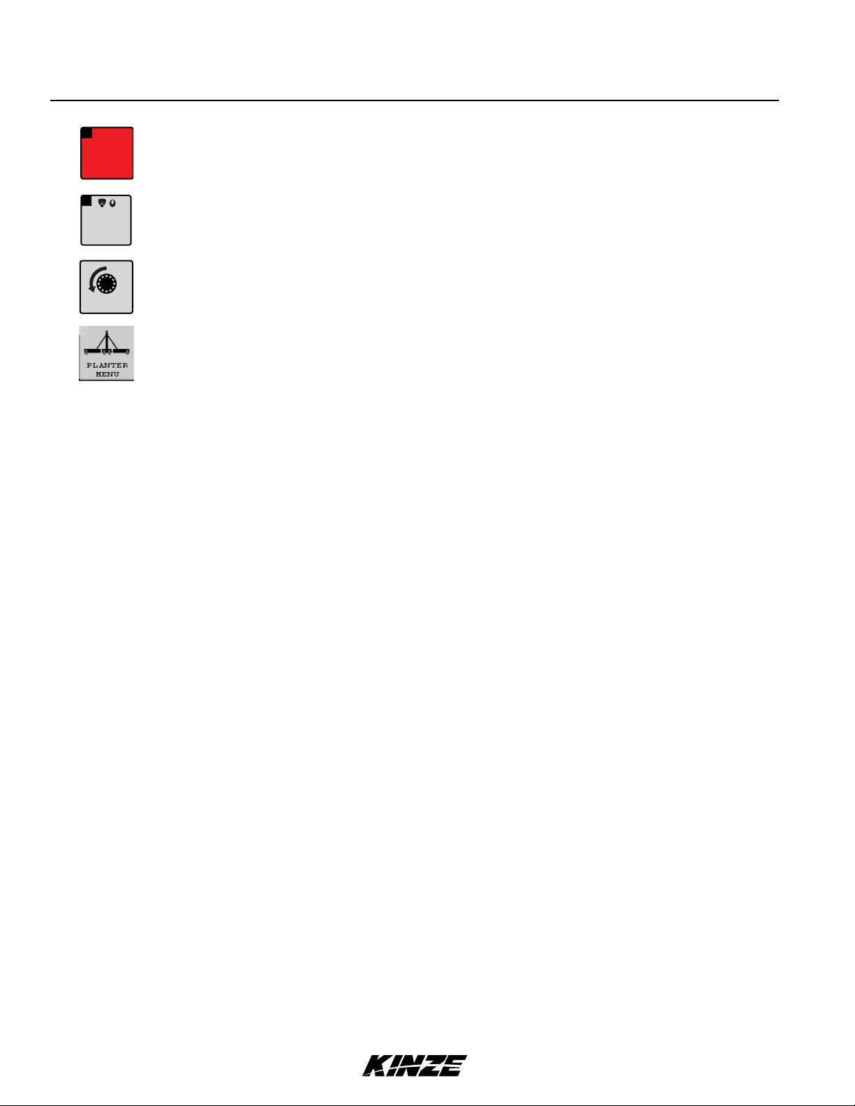
Population button opens window that lets you select a desired planting rate.
B
POPULATION
R 10.0
L 10.0
M0246ISOBUS
G
CORN
JUMP
START
Crop Type button opens window that allows you to select crop type and row spacing.
Jump Start manually turns meters on before desired speed is reached by pushing button and holding.
Planter Menu returns you to the planter menu from any screen.
8 Rev. 5/14
TM
 Loading...