

Kintech Engineering Geovane Quick Start Manual
GEOVANE
13
83
OU
S
S
GIG
5 6 7 8 9 10 3 2 132 16 58 7 4
5V
1 2 3
4 5
25
1 2 3 4 5 6 7 832 16 58 7 4
T
IGITAL INPUT 1
NEMOMETER INPUT
S
IGITAL INPUT
2
1
0
Wind direction measurements reinvented
INSTRUCTIONS
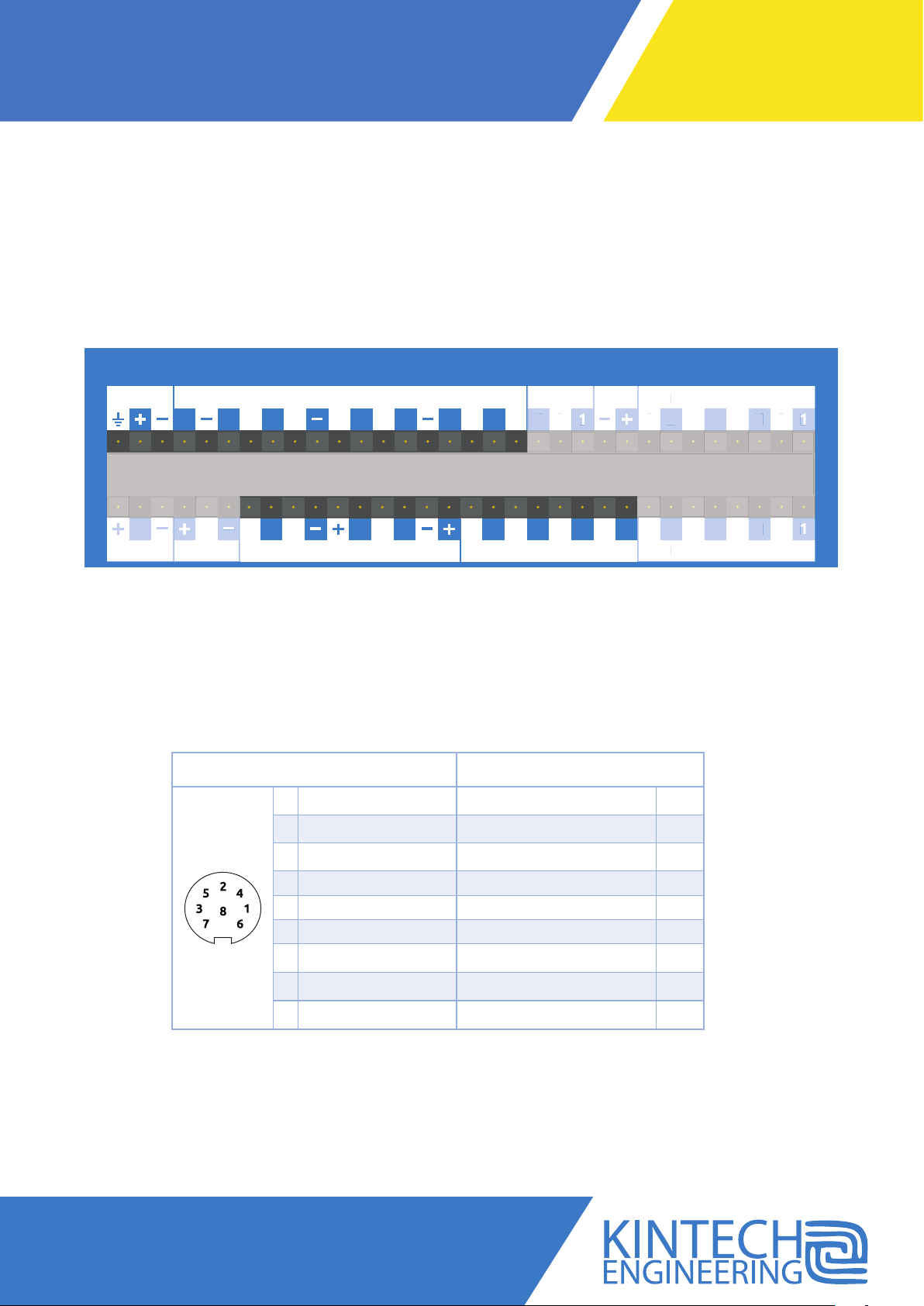
Use the following input channels on the logger to connect this sensor. See highligted input channels marked here below. The
wire colors used in the connection diagram below only applies in case the cable is supplied by Kintech Engineering.
Depending on the number of pins to be used, the number of necessary wires can range from three (frequency output) to eight.
See section 3.2 of the manual for detailed pinout and section 8 of the manual for how to configure.
GSM GPS
BAT
5V 5V
1 2 3 4
SIG
I
DIR 1 DIR 2 EXTRA ANALOG INPUTSDIGITAL INPUT 2ANALOG INPUTS
IR 1
SIG
IR 2
SENSOR PIN DESCRIPTION DATA LOGGER INPUT CHANNEL
1 2 3
1 Out (V1+) Analog Inputs 1
2 RS-485 A
5 6 7 8 9 10 3 2
4 5
25
25
OUTDIGITAL INPUT 1ANEMOMETER INPUTS
T DIGITAL INPUT 1
5V
1 2 3 4 5 6 7
XTRA ANALOG INPUT
DIGITAL INPUT 2ANALOG INPUT
2 16 58 7 4
2 16 58 7 4
Avda. Anselmo Clavé nº 37-45 - 50004, Zaragoza - Spain
Tel. (+34) 976 221 789
support@kintech-engineering.com
www.geovane360.com / www.kintech-engineering.com
3 Supply (+) BAT (+)
4 RS-485 B
5 Out ( V 2+) Analog Inputs 2
6 Out (Hz) Anemometer Inputs 1
7 Supply (-) BAT (-)
8 Out (-) Analog Inputs (-)
- Shield BAT GND
GEOVANE | WIND DIRECTION MEASUREMENTS REINVENTED
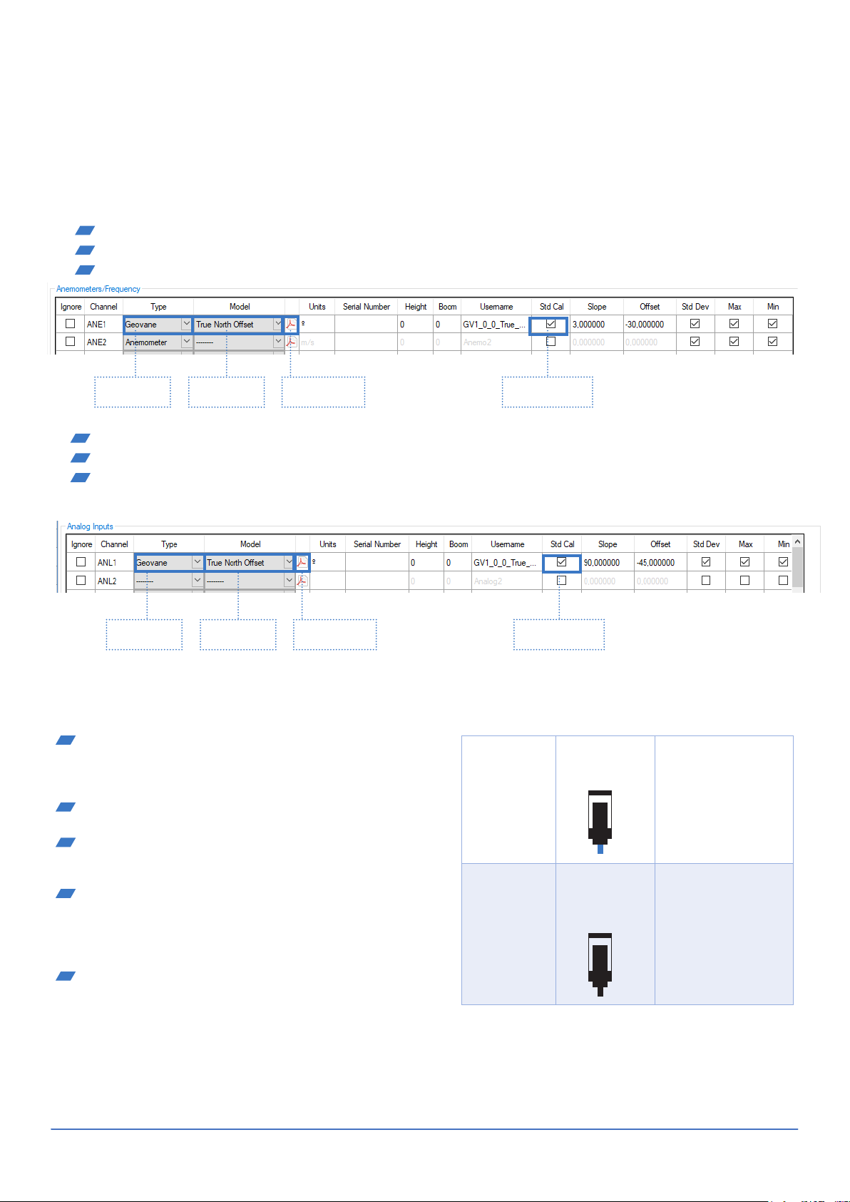
HOW TO CONFIGURE THIS SENSOR IN EOL MANAGER
Keep in mind that the configuration of a Geovane in EOL Manager has to be done according to its outputs configuration. Open EOL
Manager and go to the data logger you are working on. Open the “inputs” tab and select the following type and model:
Section: Anemometers/Frequency
Typ e: Geovane
Model: True North Offset
SENSOR
SELECTION
MODEL
SELECTION
DATASHEET
DOWNLOAD
Section: Analog Inputs
Typ e: Geovane
Model: True North Offset
SENSOR
SELECTION
MODEL
SELECTION
DATASHEET
DOWNLOAD
IMPORTANT
After configuring the sensor in EOL Manager make sure
to upload the configuration file to your EOL Zenith data
logger. See the “Quick User Guide” how to upload configuration files to the data logger.
All sensor wire shields must be connected to the data
logger GND terminal.
The data logger should always be connected to a se-
parated ground rod. Not to the lightning rod of the
tower.
For a precise measurement of the True North Offset,
the wind wane coupled to the Geovane must have, at all
times, its internal angular reference perfectly aligned
with the Geovane’s angular reference. See section 4 of
the manual.
It is recommended to always keep the RS- 485 cores
(pins 2 and 4) accessible from the ground so the Geovane can be re-configured and updated without having to
dismount it.
STANDARD
CALIBRATION
STANDARD
CALIBRATION
Metallic
measurement
mast,
grounded
Metallic
measurement
mast,
grounded
Drawing of
anemometer
incl. isolator
Drawing of
anemometer
without
isolator
The shield should be
connected to both
the Geovane side and
the data logger side
Data logger should
always be connected
to ground
The shield should
only be connected on
the data logger side
Not on the Geovane
Data logger should
always be connected
to ground
Last modified: 12.03.2018
support@kintech-engineering.com www.kintech-engineering.com
 Loading...