

1
Ⅰ.SAFE DRIVE
Rules for Safe Drive
Check must be conducted,bef ore starting the engine,to prevent mishaps and damage to components.
Only the qualified person who has passed the drive examination with a drive license is permitted to drive the
vehicle but not anybody else without a drive license.
Full preoccupation is required during drive, paying attention to the following points to avoid any possible
hurt to you by other motorized vehicles:
Do not drive too close to other vehicles;
Never contend for lane.
Strictly observe the local traffic rules.
As driving at overspeed is the cause of many accidents. Do not drive at a speed that the actual situation does
not permit.
Particular care should be exercised at the level crossing of roads, entrance and exit of parking lot or on the
autonobile lane.
During drive, grasp the left handlebar by the left hand and the throttle twist grip by the right hand,with feet
on the footrests.
2
Protective wear
1.Protective wear such as helmet with protective mask, dustproof glasses and gloves should be worn during
drive for the sake of personal safety.
2.Loose clothes are not suitable for motorcycle drive or ride as they may get caught on the operating lever
,kick ,footrest or wheel, resulting in danger.
Modification of the vehicle
Caution:
Any unauthorized modif ication of the vehicle or replacement of the original parts can not ensure driving
safety and is illicit. The user must observe the regulation s of the traffic conrtol authorities, We are no t responsible
for any vehic le with unauthorized modification.
3
Ⅱ.MAIN DATA
Item 50 type Item 50 type
Overall length 1910mm Cylinder bore x stroke
39×41.4
Overall width 760mm Compression ratio
8.8:1
Overall height 1140mm Output,max
2.0kw/7000r/min
Wheelbase 1260 mm Torque,max
2.2N.m/62500r/min
Dead weight 92kg Idling speed
1500r/min±100r/min
Payload 150kg Displacement of cylinder
49ml
Front wheel 3.25-18 Spark plug
A7TC
Rear wheel 3.00-16 Spark plug gap
0.6~0.8mm
Speed,max 45km/h
Gap of air valve
Inlake valve:0.05mm
Braking distance ≤7m(30km/h)
Exhaust valve:0.08mm
Climbability ≥18° Ground clearance
200mm
Capacity of gasoline
5.5L Ignition means
CDI
Transmission ratio
1 st gear 3.273 2nd gear 1.937 3rd gear 1.611
4th gear
1.350
5th gear
Final reduction 3.286
4
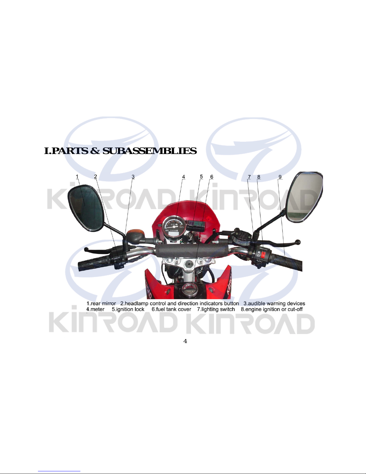
III.PARTS & SUBAS SEMBLIES
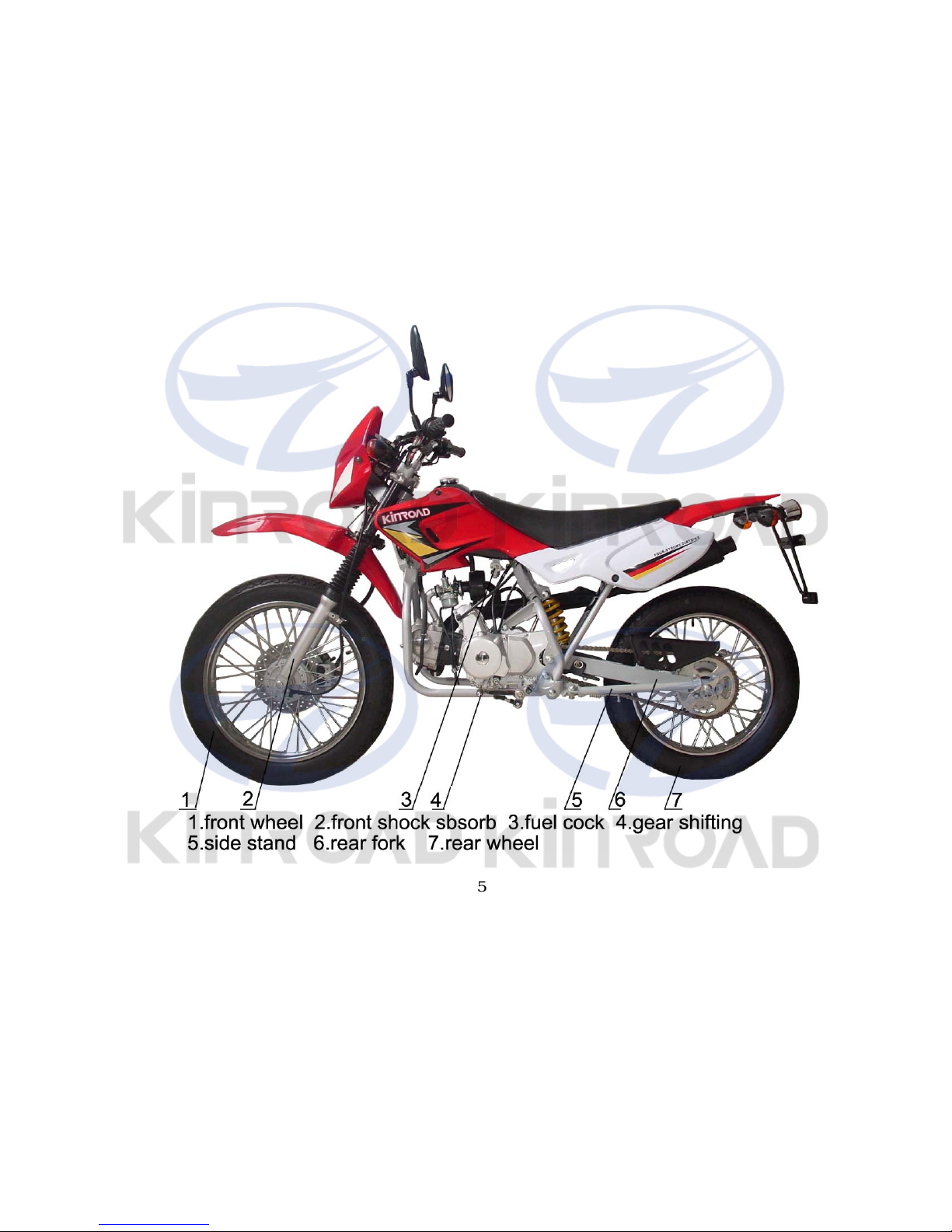
5
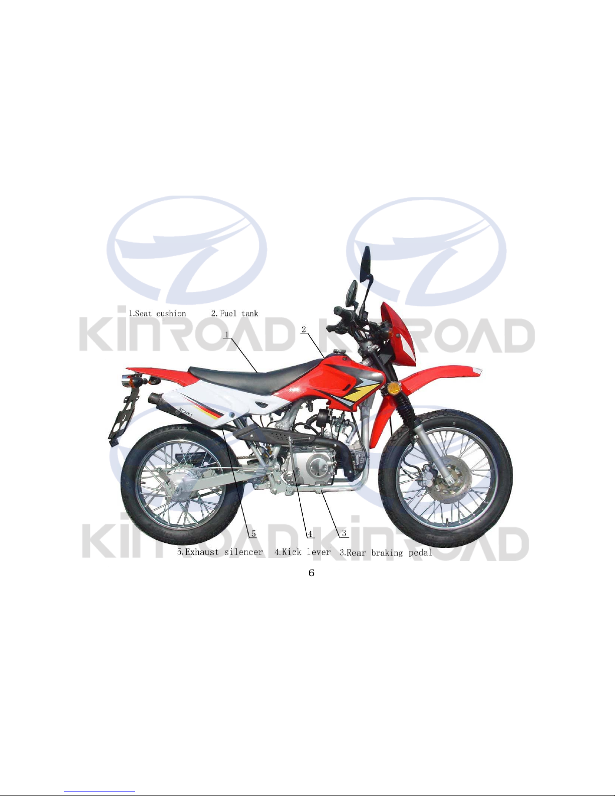
6
7
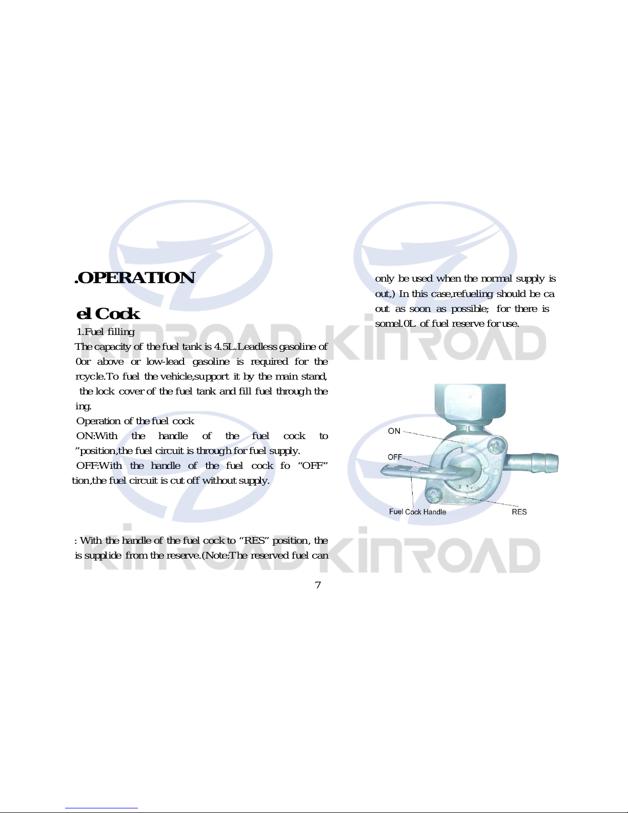
IV.OPERATION
Fuel Cock
1.Fuel filling
The capacity of thefuel tank is 4.5L.Leadless gasoline of
No.90or above or low-lead gasoline is required for the
motorcycle.To fuel the vehicle,support it by the main stand,
open the lock cover of the fuel tank and fill fuel through the
opening.
Operation of thefuel cock
ON:With the handle of the fuel cock to
“ON”position,the fuel circuit is through for fuel supply.
OFF:With the handle of the fuel cock fo “OFF”
position,the fuel circuit is cut off without supply.
RES: With the handle of the fuel cock to “RES” position, the
fuel is supplide from the reserve.(Note:The reserved fuel can
only be used when the normal supply is run
out,) In this case,refueling should be carried
out as soon as possible; for there is only
somel.0L of fuel reserve for use.
8
Engine Startin
g
Warning:Never startthe engine in a closed
p
lace orwarehouse orwarehouse asthe
exhausted
gas
from the vehicle contains toxic
carbon monoxide.
1.Se
t
the keyofthe ignition switch to
“ON”
p
osition.
2.Ascertain the neutral
p
osition,where it
should
b
edisplayed.
3.Ascertain the amount o
f
fuel in the tank,
4.Se
t
the fuel cockhandle to “ON”position.
★T
o
startacoldengine;
1.Pull u
p
the chokebarofthe carburetor(to
close the choke
)
.
2.Rotate the throttle twist
grip
by
1/8to
1/4turn.
3.Start the en
g
inebythe electric orthe kick
startin
g
system.
4.Sli
g
htlyturn the throttle twistgripto
increase the s
peedof
the engine so asto
war
m
upthe engine.
5.Turn the carbureto
r
chokebardownward
to full
yop
en the choke whenthe engine is
sufficientl
y
warmedup.
★Caution:
The engine can only be started after the
neutral position is ascertained.Otherwise
accident will happen.
Unnecessary idle running(especially at a
high speed) is harmful to the engine.
★ Procedures for stopping the engine:
1.Release the throttle twist grip to slow
down the engine.
2.Turn to the neutral position.
3.Se
t
the ignition switch keyto
“OFF”
p
osition.
4.Set the fuel cockhandle to “OFF”
position.
Switches on Right Handle bar

9
Electric start button
The electric start button is located below the right handlebar.When the
ignition switch is set in “ON” position and the engine is in the neutral
position, push the button to start the engine
Light switch
The front light switch has three positions,
And“●”(a white point).
When the switch i s in this position,the front head
li ght button ,tail and meter lights are all lit up.
When the switch is in this position,the tail, betraying and m eter
Iights are lit up.
“● ”When it is in this position. The front illumin ator, tail, betraying and
meter lights are all off.
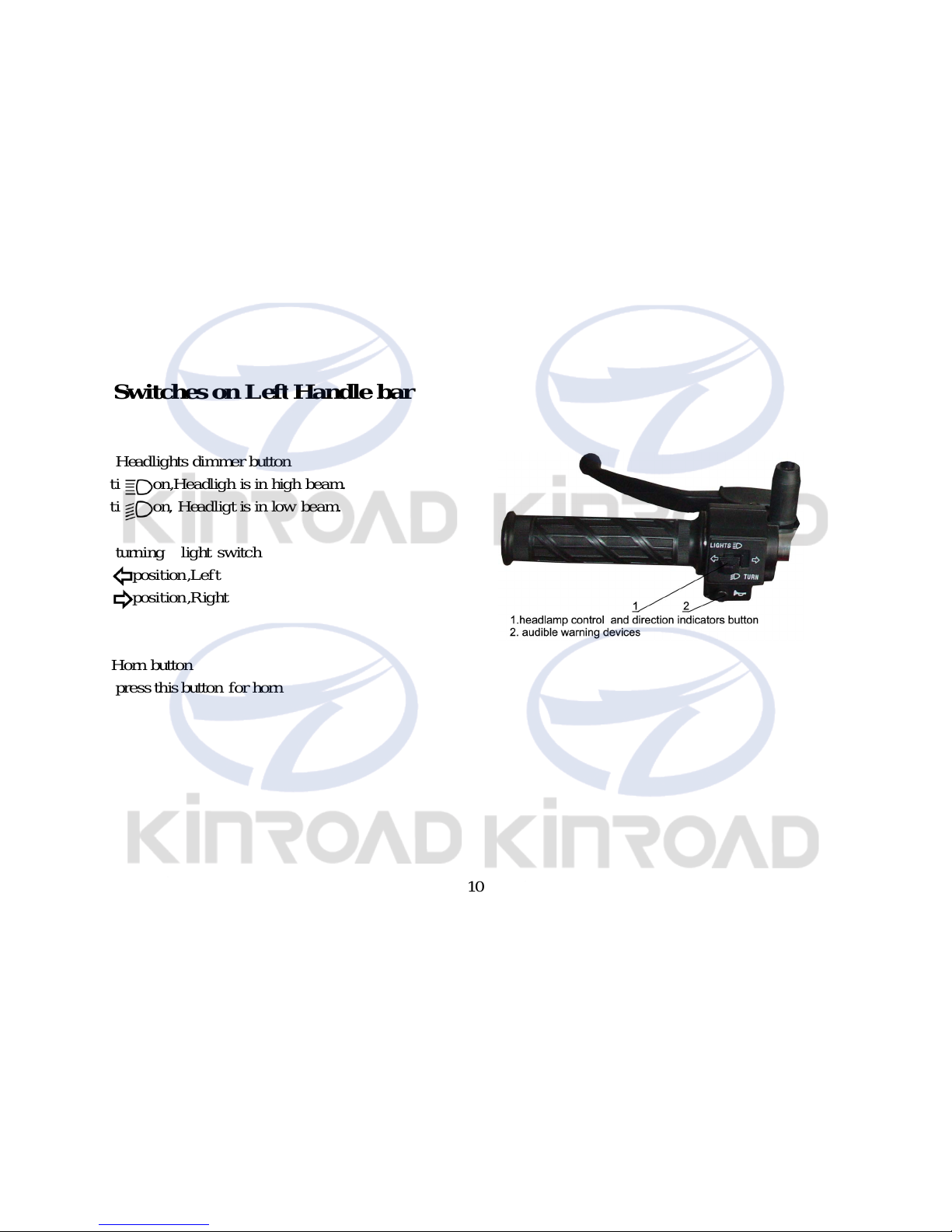
10
Switches on LeftHandle bar
1. Headli ghts dimmer button
Positi on,Headligh is in hig h beam.
Positi on, Headligt is in low beam.
2. turning light switch
position,Left
position,Right
3.Horn button
press this button for horn
11
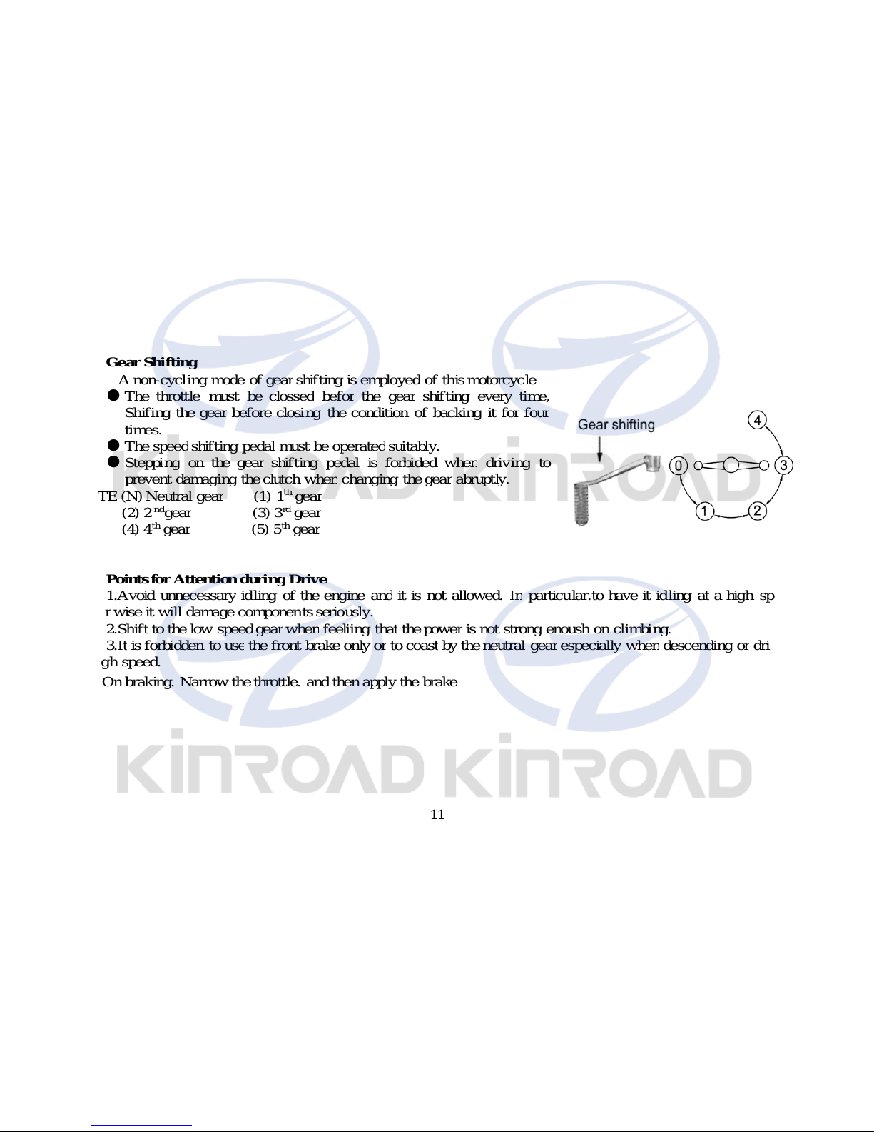
Gear Shifting
A non-c
y
clingmode o
f
gear
shift ingis employed ofthis motorcycle
● The throttle must
b
e c losse
d
b
eforthegearshift ingeverytime,
Shifin
g
thegea
r
b
efore closingthe condition o
f
b
ackingit forfou
r
times.
● The s
peed
shift in
g
p
edalmustbeoperatedsuitably.
● Ste
pping
on thegearshift in
g
p
edal is forbided whendrivingto
p
revent damagingthe clutch whenchangingthegearabruptly.
N
OTE
(N)
N
eutralgea
r
(1)
1
th
gear
(2)
2
nd
gear
(3)
3
rd
gear
(4)
4
th
gear
(5)
5
th
gear
Points for AttentionduringDrive
1.Avoid unnecessar
y
idlingofthe engine andit is not allowed. I
n
p
articu lar.to have it id lingatahighspeed.
Othe
r
wise it will damagecomponen ts seriously.
2.Shif
t
to the low spee
d
gear
whenfeeliingthatthepoweris not strongenoush on climbing.
3.I
t
is forbidden to usethe frontbrake onlyortocoas
t
by
the n eutralgearespeciallywhendescendingordrivin
g
athighspeed.
4.On braking. Narrow the throttle. and then apply the brake

12
V.Checki
ng,
Adj
ustm
-
entan
d
Mai
ntenance
Machi
ne
Oil
Checki
ng
★The vehicle should be checked for
machine oil before drive by sup-porting
i t with the
Main stand on a flat ground.The oil
livel should be between the upper and
lower
Lines of the oil gauge. Which is not
screwed into the filling orifice.
★ High quality 4-stroke machine
oil. Class SE or SD in API classif i-
cation.of SAE15W-40 in viscosity will
help maintain a long service life or the
engine.In case those are not available,a
substitute suitable for the ambient
temperature of application should be
selected according to the table on the
right side.
R
enewalo
f
Machi
ne
Oil
Machine oil plays a very important
role in the normal operation of the
engine and for this reason,it is necessary
to check the motorcycle for machine oil
periodically and renew the oil once
every800-1,000k m of driving by the
follow ing procedures.
Remove the screw plug from the
bottom of the hot engine to drain off all
old oil.
Wash the oil filter screen clean and
remount it really to positi on.Then fill in
0.8L fresh machine oil and start the
engine for idle running2-3 minutes.
Let the engine stop for 1-2
minutes and check to see whether the
oil level is in between the upper and
l ower lines of the oil gauge.
Do not use any machine oil of a
different grade than the specif ied one
toavoid machinery failure.

13
Cl
eaning ofmachine o
il
tank
Check-up ofSpark Plug.
1.Drain off all the run –in machine oil from
the o il tank.
2.Dismount the related parts.
3.Wash clean all the related parts.
4.Fill in the required oil.
* This job should not be done by untrained
persons but shall be done at an authorized service
center. 1.Remove the cap of spark plug and screw off
the spark plug by the plug wrench.
2.Clean the spark plug all aroud or replace it
if i t is corroded or there is too much deposit on it.
3.Regulate the gap of the spark plug to 0.6-
0.7mm.
4.The spark plug of the designated type should
be used. The applicable type of spark plug: NHSP
LD D8TC made i n China.

14
Check-up & Cleaning ofAir Filter
Take out the air filter and check if it is
contaminated.
Dismounting:
Remove the right side cover,take out the screw
and disassemble the air filter.
Cleaning:
Wash the filter i n cl ean washing oil and wipe it
dry with dry cloth.
Soak it in clean machine oil,squeeze it dry and fit
it back to position.
Recommended oil:15W/40QE
Caution:
The air filter element for use must be intact or the
enine will suck in dust and dirt, resulting in a shorter
service life of the engine.
Water should be prevented from entering into the
filter in washing the vehicle.
The filter shall neve
r
b
e cleanedwithgasoline oran
y
otheragentofalowignitionpoint.
15
AdjustmentofThrottle Cable
Make sure that the adjusting nut of the throttle
cable and l ocking nut work normally.
Check to see if the throttle twist grip is with the
required free operating movement.
Therequired free operating movement:2-6mm.
If the grip can not be so moved freely.turn the
adjust ing nut to ensure it.
After adjustment, start the engine and check for
the free operating movenent again,Repeat the
adjustment if necessary until it is as required.
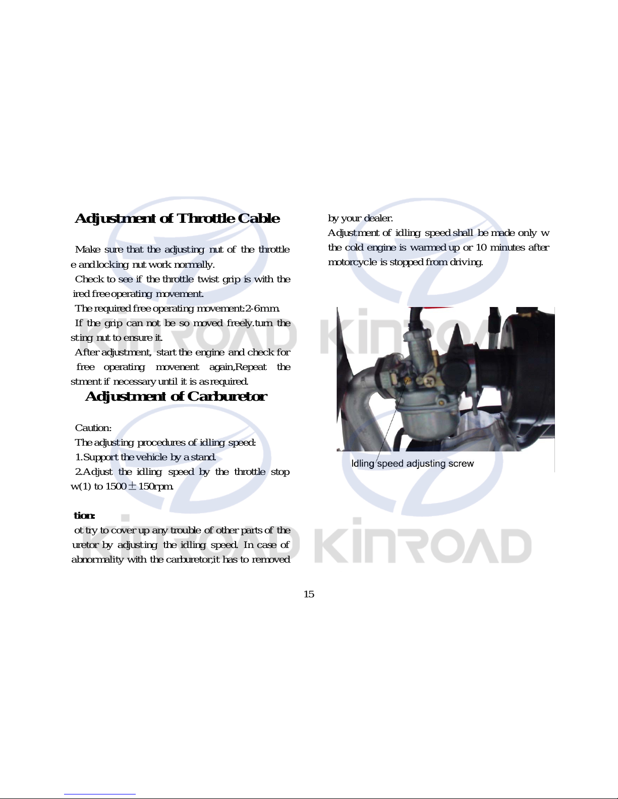
AdjustmentofCarburetor
Caution:
The adjusting procedures of idling speed:
1.Support the vehicle by a stand.
2.Adjust the idling speed by the throttle stop
screw(1) to 1500±150rpm.
Caution:
Do not try to cover up any trouble of other parts of the
carburetor by adjust ing the idling speed. In case of
any abnormality wi th the carburetor,it has to removed
by your dealer.
Adjust ment of idling speed shall be made only when
the cold engine is warmed up or 10 minutes after the
motorcycle is stopped from driving.

16
Check-up & AdjustmentofAir ValveGap
Noise will stem from too big gap of the air valve. However if there is too small gap or even no gap at all,
closing of the valve will be hindered, which will cause burn of the valve and output drop. Therefore, the air valve gap
must be checkedperiod ically.
The gap of the air valve should be inspected and adjusted with a cold engine by the following procedures:
1.Remove the capsof the central hole and the top hole (the ignition timing observation hole)in the left crankcase
cover.
2.Remove the capsof the two air valves on the cylinder head.
3.Insert the “T” key into the central hole of the crankcase cover, jam it against the nut of the flying wheel and
then turm the flying wheel clockwise nutilthe engraved “T” mark on the flying wheelalin\gns with the engravedline
on the top of the crankcase cover.Swing the rocking arm slightly.A l oose rocking arm(which indicates the existence
of clearance) shows that the pi ston is i n the upper stop position of the compressing t\stroke, where the valve can be
adjusted. A tight rocking arm means thar the piston is in the lower stop position of the compressing stroke, In this
case, continuously turn the “T” key clock wise for 360 degrees until the alignment of those engravd marks, where the
valve canbe adjustd,Af terwards, check the valve gap by inserting a feeler in betweenthe valve adjusting screw and
the end of the valve.
The specified air valve gap :0.05mm for the intake and exhaust valves respecively.
Brake Checking
(1) pull up the front andrearbrakes respectively and check for wearof the brake shoes. If the mark“△”onthe
brake drum cover aligns with that “△ ” on the brake cam, it means that the brake shoes are already worn to the limit
andhave to be replaced.
(2) Replacement should be carriedout at a designated service center and it is recommended that the parts made
byour company areusedtherein.

17
AdjustmentofFrontBrake
(1) The front brake has a free operating
movement of 10-20mm as shown in the figure on the
right side.
(2) inspect the reseivoir capacity and refill if
necessary in order to maintain proper level in the
reservior.This should be the major project of your
regular inspection
(3) check the front brake lining for its worm
depth.if its worn depth is up to the limited mark,
replace the brake lining.if the lining doesn’t have
limited mark but a concave slot as the figure,replace
the lining while its worn depth up to the bottom of
concave slot.replacement of a pair of linings shall be
conducted sumultaneously despite only one of them
is worn.
18
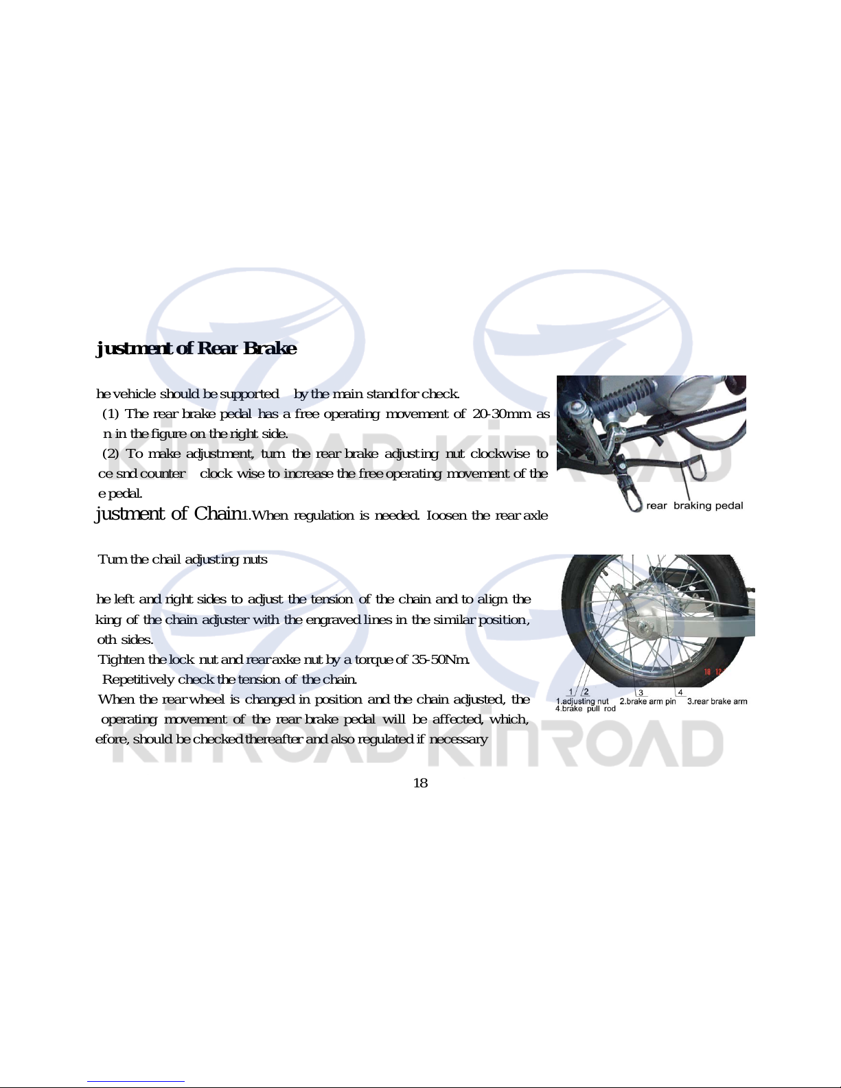
Adjustment ofRearBrake
★The vehicle should be supported by the main stand for check.
(1) The rear brake pedal has a free operating movement of 20-30mm as
shown in the figure on the right side.
(2) To make adjustment, turn the rear brake adjusting nut clockwise to
reduce snd counter clock wise to increase the free operating movement of the
brakepedal.
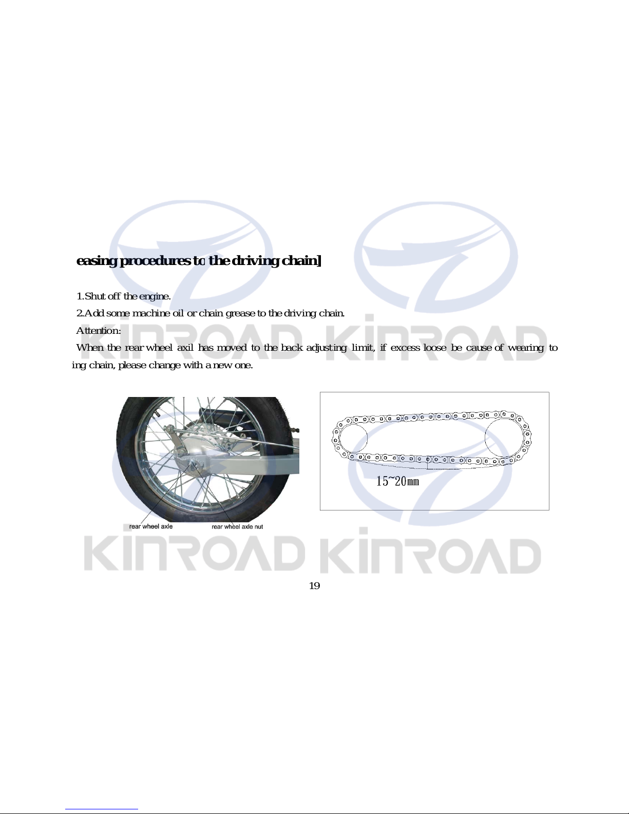
Adjustment of Chain
1.When regulation is needed. Ioosen the rear axle
nut
2.Turn the chail adjusting nuts
on the left and right sides to adjust the tension of the chain and to align the
marking of the chain adjuster with the engraved lines in the similar position,
on both sides.
3.Tighten the lock nut and rear axke nut by a torque of 35-50Nm.
4. Repetitively check the tension of the chain.
5.When the rearwheel is changed in position and the chain adjusted, the
free operating movement of the rear brake pedal will be affected, which,
therefore, should be checkedthereafter and alsoregulated if necessary
19
[Greasing procedures tothe driving chain]
1.Shut off the engine.
2.Add some machine oil or chain grease to the driving chain.
Attention:
When the rear wheel axil has moved to the back adjust ing limit , if excess loose be cause of wearing to the
driving chain, please change with a new one.
20
VehicleWashing
Cleaning the vehicle reularly can slow down the color fading of its body and make it easier to check if there is
anydamage and oil leakage with if.
Caution:
Washing the motorcycle with over-pressurized water may cause damage to some of its components. Therefore,
do not jet over-pressurized water directly on to the following parts:
——Wheel hub
—— Exhaust pipe
——Fuel tank and lower portion of cushion
——Carburetor
——Head lock andignition switch
——Meters
(1) After pre-wiping ,the vehicle should be washed with clean water to remove dirty residues so as to prevent
corrosion. Plastic subassemblies should be cleaned by wiping with cloth or foam soaked i n neutral detergent solution,
followed by washing with cleanwater.
(2) Afterthe cleanedvehicle is air dried, greasethe chain andrun the engine atidling speedfor a fewminutes.
(3) Prior to driving, carefully check the braking systemrepeatedly and repair or adjust it if necessary.

21
Instructions forStorage
Forthe motorcycle not tobeusedforalon
g
p
eriod
o
f
time, forexampl e,in wintertime,some stepsshould
b
etakentoperventmalfunction ofanddamagetoits
com
p
onen ts which migh
t
b
e cause
d
by
longstorage,
Besides,
b
efore the longstorage,proper maintenanc
ehastob
e carride out forfearthatit migh
t
b
eforgotte
n
whenthe vehicle isputbak into u seafterstorage.
1.Chan
g
eengine oil andoil filter.
2. Drain of
f
fuel from the fuel tank andcarburetor,
s
pray
atomized anti-r ustoil noto the inside wall ofthe
tank an
d
then close the tank.
Attention:
I
f
the storage will lastformore than one month,
feul in the carbureto
r
mustbefullydratinedoff,which is
ver
yimp
ortantbecausei t will helpensurethatthe
Carbureto
r
maintai ns its normalperformance afterthe
stora
g
e.
Warnin
g
:
Gasoline is inflammable an
dmay
causefire an
d
evenexplosion under certain conditions. Therefore, do
not smoke, make fire o
r
have anyfire lef
t
b
ehind on
drainin
g
offfuel.
3.Takeout the spar
k
plug,p
our about 15-20ml o
f
cleanengi ne oil into the cylinder, stepdown the kick
leve
rrep
ectit ivelyforseveral, stepdown the kick leve
rrep
etit ivelyforseveraltimes so asto have machine oil
distribute
d
all overthe engine andfinallyfit the spar
k
plug
back
on.
Attention:
The i
g
nition switch mustbesetto “ ¤ ”(off
)
p
lsitionbefore steppingdown the kick lever. T
o
p
rotec
t
the ignition system from damage, the spar
k
plug
should
b
einsertedin its capandearthed.
4.Was
h
the vehicle clean, wipeitdryandapplya
n
evencoatofwaxto thepaintedsurfaceandacoato
f
antir ustoil the chrome-pla ted surface.
5.Inflate the t
y
re asrequiredan
d
pad
the vehicle u
p
by
woodenblocks with the two wheels clearofthe
g
round.
6.Pu
t
the vehicle in a shadyandcoolplace fre
e
from humidityanddirectsunshine andcoverit
prop
erll
y
(
but not withplastic orothe
r
p
ainte
d
materials).Ifthereisgarage, store it therein.
Resumption ofServise afterstorage
22
1.Remoe the coverin
g
andcleanthe vehicle. Change the lubricatingoil ifthe vehicle ha
s
beenoff
serv ice fo
r
over4months.
2.Drain offthe remainingatomized antirustoil from the fuel tank, followedbyfillingit with fres
h
g
asoline
therein.
3.Prior to driving, all the requiredcheck-upsmustbe made. Itisbetterto drive it atalowspeedin aplace o
f
traffic safetyto testitsperformancebefore normal drive.
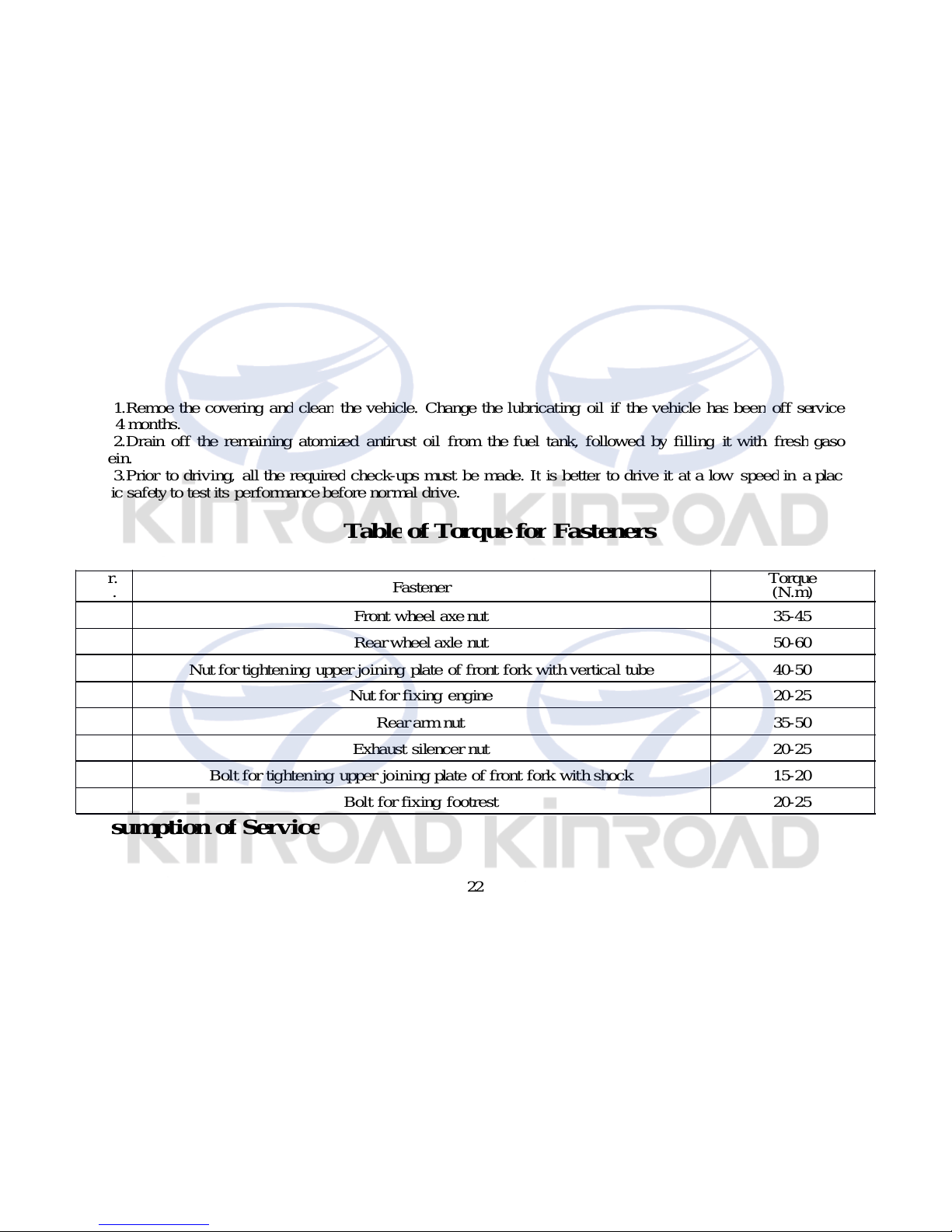
TableofTo rque forFasteners
Resumption o
f
Servic
e
S
er.
N
o.
Fastener
Tor
q
ue
(
N.m
)
1 Front wheel axe nut 35-45
2 Rear wheelaxle nut 50-60
3 Nut for tightening upper joining plate of front fork with vertical tube 40-50
4 Nut for fixing engine 20-25
5 Rear arm nut 35-50
6 Exhaust silencer nut 20-25
7 Bolt for tightening upper joining pl ate of front fork with shock 15-20
8 Bolt for fixing footrest 20-25
23
1.Remove the coverin
g
andcleanthe vehicle. Change the lubricatingoil ifthe vehicle ha
s
beenoff
serv ice fo
r
over4months.
2.Char
g
ethebatteryandremountit.
3.Drain of
f
the antirustsolution from the fuel tank, followedbyfillingfuel therein to therequiredlevel.
4.Prior to drivin
g
,testthe vehicle atlow speedin a saf
e
p
lace.
Maintenance Routine Dia
g
ram
The vehicle should
b
e undergood maintenance asspecifiedin the follow ingtable, where:
“I”means:Check, cleanin
g
,adjustment, lubrication and/orreplacement areneeded.
“C”means:Cleanin
g
is needed.
“
R
”means:Replacementis needed.
“A”menas”Ad
j
ust mentis needed.
“L”means::Lubrication is needed.
“*”means:This item o
f
maintenance shouldbe carriedout ata service centre. Itma
y
b
e also donebythe use
r
himself with referenceto this manualprovided he hasspecial tools, spar
e
p
artsandis capable ofthisjob.
“** ”means:This item ca
n
onl
y
b
e carriedoutbythe serviceman a
t
p
rof essional service centerin orderto
ensure safet
y
.
N
otes:1.Ma intenanceshouldbe conductedmore frequentlywhenthe motorcycod drevesin dustyareas.
2.When the read-ou
t
ofthe odometer exceeds the maximum figures specifiedin the table, maintenance should
b
estill cycledaccordingto the intreval ofmileage statedherein.
TableofMaintenance

24
Frequency
Items of Maintenance
Item /frequency
Odometer km (Note2)
1000k m 4000k m 8000k m 12000k m remak
* Circurt offuel system I I
* Fuel filter C C C C
* Throttleoperatingsystem I
* Choke of car bu retor I I
Airfilterelement NoteI C C C
Soark olug I
* Airvalve gap I
Airvalve gap I
Enginelubricatingoil R -yearly One replacement every 300km, 600km, 1000km, 2000km.
Lubriatingoil screen R -yearly C
* Tensionof chain A A A A
* Ldlingspeed of carbureor I I I I
Drivingchain I.L I.L I.L I.L
Baliery Monthty I I I
Wearof brake shoers I I I I
AlsofordiscstyleRear braking systems I I I I
** Brakint l iq uid hose R –4year I I I I
** Cupofbrakingliquic I I I I
** Brakinglicud R–2year One replacement every twoyear
** Front braking system I I I I
* Rear braking lightswrtch I I I I
* Lightchangingof front illuminator I I I I I
Clutch III I
* Sidestand I I I
* Suspension I I I
** Nuts,bolts & osher fastene’s I I I
** Bearingof steeringhandne I I

25
V.ELECTRICAL DIAGRAM
 Loading...