


Kinpo Electronics, Inc.
User's Guide
to the
Modem Icon Utility
Model No.: A200A(A2)
Version : E1
Date : Oct. 22, 1999
Software: Itex
User's Guide to the ITeX Modem Icon Utility
The Modem Icon Utility will allow the u s er to monitor the ADSL modem's connection and
ATM/ADSL states, setup the PVC values, and run a few diagnostics tests.
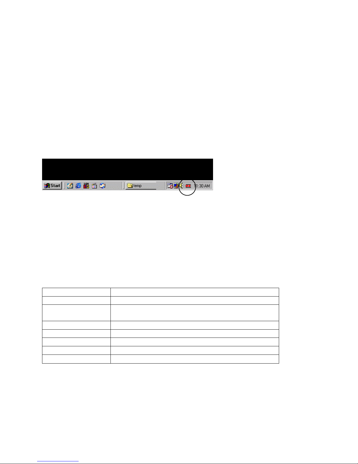
Getting Started
Before proceeding forward, please make sure that the modem has been installed
correctly. Contact your network administrator if help is required. The Modem Icon
Utility is displayed as an icon on the task bar of the windows desktop screen. As shown
below.
Using the Modem Icon
The Modem Icon serves two purposes: 1. To display the modem status and 2. To allow
the user to monitor the ADSL modem.
Modem Status
The Modem Icon consists of two lights side by side. These lights are used to display
the state of the modem. The left light signifies data is being transmitted whereas the
right light signifies informat i on is being received. The state of the modem can be
determined as follows:
Code Description
Red, Red No signal
Black/Yellow or
Modem is connecting
Yellow/Blk flashing
Green, Black Modem is transmitting data
Black, Green Modem is receiving data
Green,Green Modem is transmitting and receiving data
Black, Black Modem is idle, connected
∅
Modem is disconnected, or a problem exists
1

Placing the mouse cursor on the Modem Icon will show a summary of the modems
status by displaying the modem's state, upstream line rate and downstream line rate.
Monitoring the ADSL Modem
ITeX ADSL Test Application
Pointing to the Modem Icon, and clicking on the left mouse button will display the ITeX
ADSL Test Application window. From this window, the user will be able to run
Diagnostics, review the ADSL modem status and view the ATM/ADSL Statistics. For a
more detailed explanation of each window, turn to the appropriate section in this manual
for each menu.
2

Modem Icon Menu
Pointing to the Modem Icon and clicking on the right mouse button will display the
Modem Icon options window. From this window, the user will be able to: a)
"Disconnect" the modem from or "Connect" the modem to the central office equipment;
b) Run a diagnostic test to test the modem; c) Monitor the ADSL modem status; d)
Monitor various ATM/ADSL statistics and e) configure the PVC values for RFC1577 and
RFC1483.
Connecting and Disconnecting the ADSL Modem
This option will allow the user to connect to or disconnect from the central office
equipment. If the modem is disconnected, simply choose the connect option and the
ADSL modem will start to connect. To disconnect the modem, simply select the
disconnect option.
ADSL Status Menu
The ADSL Status menu allows the user to monitor the ADSL connection as well as
monitor the transmit and receive line rates.
3

ADSL State - displays the current status of the modem. These states are: Connected,
Connecting, and Disconnected.
Protocol - The protocol section displays which ADSL standard is being used.
Transmit /Receive Rate - In the Transmit and Receive section, the user will be able to
see what kind of line rate is being achieved for both upstream and downstream line
rates.
ATM / ADSL Statistics Menu
From this menu, the user will be able to see E rror Count Information, ATM Tran smission
statistics and ATM Receive statistics.
Error Count Information
Re_HSK Count - The number of times handshaking has occurred.
CRC error count - The number of cyclic redundancy check (CRC) errors accumulated
during showtime. The count will be reset to zero after the next handshaking. During
showtime, the receiver keeps checking the CRC check sum for each received
superframe. If there is a mismatch between the received check sum and the locally
calculated check sum, a CRC error has occurred.
ATM HEC - The number of ATM header error che ck (HEC) errors accumulated during
showtime. The count will be reset to zero after the next handshaking. Afte r entering
showtime, the ATM TC layer at the reciever will undergo a cell delineation hunting
process by finding the header of each received ATM cell. After successfully finding the
cell delineation, the ATM TC layer will keeps checking the HEC check sum for each
received ATM cell. If there is a mismatch between the received check sum and the
locally calculated check sum, an ATM HEC error has occurred.
4

ATM Transmission Side Statistics - displays the number of packets transmitted.
ATM Receive Side Statistics - displays the number of good and bad packets received.
Configuration Menu
The Configuration menu will allo w the user to check or change the ADSL network
modems PVC values for RFC1577 and RFC1483. To change the PVC values, simply
select one of the RFC protocols, enter the VPI and VCI values, and then click on the
PVC Setting button. Click Yes when asked to reboot the system. Click on the Close
button to close the configuration window.
5

FCC Information
Radio Frequency Interference Statement
This equipment has been tested and found to comply with the limits for a Class B digital
device, pursuant to Part 15 of the FCC Rules. These limits are designed to provide
reasonable protection against harmful interference in a residential installation. This
equipment generates radio frequency energy and if not installed and used in
accordance with the instructions, may cause harmful interference to radio
communications. However, there is no guarantee that interference will not occur in a
particular installation. If this equipment does cause harmful interference to radio or
television reception, which can be determined by turning the equipment off and on, the
user is encouraged to try to correct the interference by one or more of the following
measures:
Reorient or relocate the receiving antenna.
Increase the separation between the equipment and receiver.
Connect the equipment into an outlet on a circuit different from that to which the
receiver is connected.
Consult the dealer or an experienced radio/TV technician for help.
Notice: Any change or modification not expressly approved by the Guarantee of the
equipment authorization could void the user's authority to operate the
equipment.
This device complies with part 15 of the FCC rules. Operation is subject to the following
two conditions:
(1) This device may not cause harmful interference and,
(2) This device must accept any interference received, including interference that may
cause undesired operation.
The class B digital apparatus meets all requirements of the Canadian Interference Causing Equipment Regulation.
Cet appareil numerique de la class B respecte toutes les exigences du reglement sur le
materiel brouilleur du Canada.
6
 Loading...