

Kino Flo BAL-455M User Manual
Operation Manual
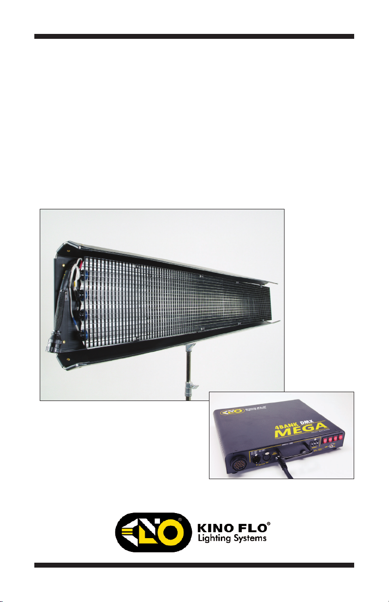
Mega 4Bank DMX
Part No. 3100054 Rev A 09-18-2013

System
CFX-9604 8ft Mega 4Bank Fixture
CFX-7204 6ft Mega 4Bank Fixture
MTP-K81 Kino 81 Mount w/ Junior Pin (28mm)
X19-25M Mega 4Bank Extension, 25ft
BAL-455-M120 Mega 4Bank DMX Ballast, 120VAC
BAL-455-M230 Mega 4Bank DMX Ballast, 230VAC
Each Mega 4Bank DMX System consists of:
1 Mega Fixture
1 Mounting Plate
1 Extension Cable
1 Mega 4Bank DMX Ballast
True Match Lamps
722-K32-S 6ft Kino KF32
722-K55-S 6ft Kino KF55
962-K32-S 8ft Kino KF32
962-K55-S 8ft Kino KF55
2
®
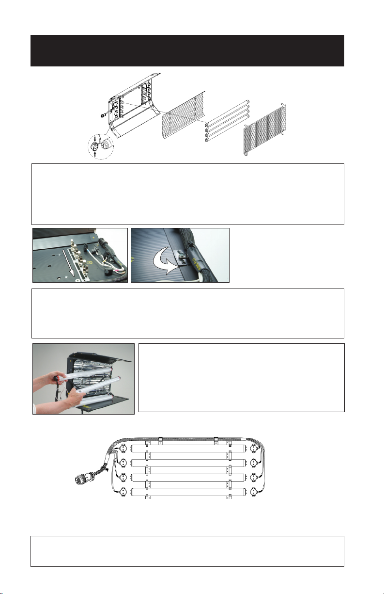
Fixture Assembly
(X2)
The Mega 4Bank xture is comprised of two removable Louvers, a Reector and
a Lamp Harness. The Louvers and Reector are held in place with Velcro fasteners.
The Lamp Harness is secured by means of a ¼ turn fastener and two clips.
Note: The 8ft xtures include two 4ft louvers; the 6ft xtures include two 3ft louvers.
To Release the Lamp Harness
Remove the harness from clips located under the reector. Rotate the ¼ turn fastener
clockwise to release harness.
The lamps can operate independent of the xture
allowing them to be built into sets or custom soft boxes
or hand-held as a single tube for an eye-light.
WARNING: Always use safety-coated lamps to avoid
injury if lamp breaks.
Lamp Harness Color Codes
Red
Yellow
Black
Blue
Mega 4Bank Harness
The Harness wiring is color-coded. The same color-code must match at each end of
the lamp for proper operation.
3
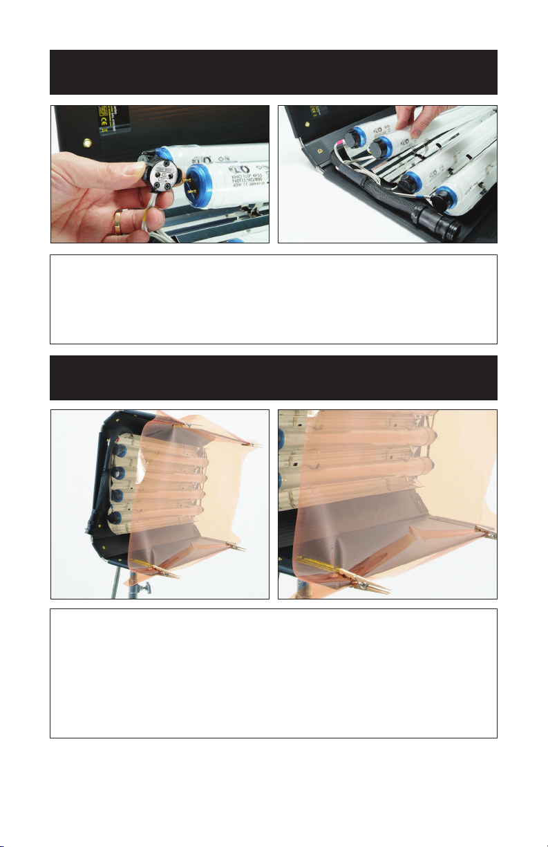
Inserting Lamps
Locking Lamp Connector:
Depress both tabs on lamp connector and apply to lamp pins.
Match the Harness color-codes at each end of the lamp.
Push lamps into the xture’s Lamp Holder Clips.
Gelling the Fixture
Restricting the airow around the lamps can cause the lamps to
operate hotter. This increased heat will raise the lamp’s color
temperature and green spike. Therefore, it is recommended to
clip gels to the doors of the xture.
Remove louvers. Do Not clip gels to louver. Do Not block the
xture ends in a manner that restricts airow.
4
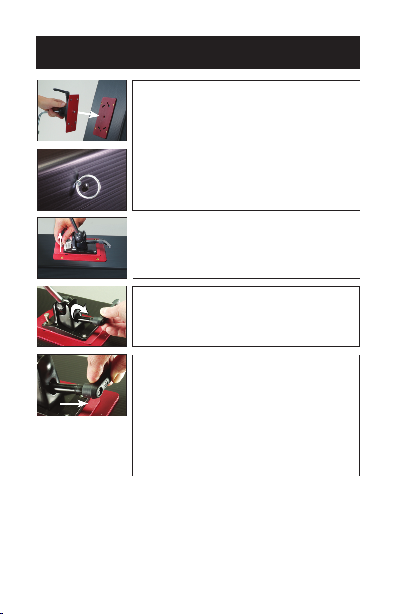
Mounting the Fixture
Align the center pin of the mounting plate
(MTP-K81) to the center hole on the mating
plate. Rotate plate clockwise until the four
shoulder rivets drop into the receptacle.
A locking pin will snap into place when
the plate is properly seated.
The Silver Rings provide attachment points for
a safety chain.
To remove the plate, pull up on the locking pin
and reverse the mounting procedure.
A 180° turn loosens the orientation of the mount.
A right turn tightens the mount.
The tension on the lock lever may be adjusted
by pulling the handle away from the mount.
This disengages the handle from the screw
mechanism and allows it to be reoriented.
Note: You can also use a screwdriver to adjust
the travel. Pull back on handle and adjust the
screw in the center of the handle.
5
 Loading...