

KINNEY KTC SERIES, KTC-112, KTC-60 Installation, Operation And Maintanance Manual
™
Manual 1845-2
KINNEY ® KTC
SERIES
Two Stage, Triplex Rotary Piston P u m p s
Models
KTC-60 KTC-112
INSTALLATION
OPERATION
MAINTENANCE
REPAIR
MANUAL
WARNING
DO NOT OPERATE BEFORE
READING MANUAL.
02/2006
ADVANCING THE STANDARDS IN VACUUM TECHNOLOGY
4840 West Kearney Street
Springfield, Missouri USA 65803-8702
Tel 417 865-8715 800 825-6937 Fax 417 865-2950
E-mail: vacuum@tuthill.com
tuthillvacuum
blower.com
! WARNING
USE OIL MIST ELIMINATOR WHEN OPERATING
PUMP. ENSURE ADEQUATE VENTILATION
DO NOT OPERATE
WITHOUT BELT
GUARD
809762-
The above safety instruction tags were permanently affixed to
your pump prior to shipment. Do not remove, paint over or
obscure in any manner.
Failure to heed these warnings could result in serious bodily
injury to the personnel operating and maintaining this equipment.
A000
NOTICE
REFER TO MANUAL SAFETY INSTRUCTIONS.
! CAUTION
DO NOT VALVE OR RESTRICT PUMP
DISCHARGE OPENING.
WHEN DISCHARGING INDOORS.
809765-A000
SAFETY PRECAUTIONS FOR ROTARY PISTON PUMPS
Please read the following safety information on this page before operating your vacuum pump.
• Do not operate the pump without the belt guard properly attached. Disconnect the pump motor from the electrical
supply at the main disconnect before removing the belt guard. Replace the belt guard before reconnecting the
wer supply to the pump motor. Operating the pump without the belt guard properly installed exposes personne
po
in th
e vicinity of the pump to risk from rotating drive component
• Do not operate the pump with oxygen-enriched gas (greater than 20% by volume) in the suction line, unless the
pump has been prepared with an inert fluid suitable for the application.
Pumping oxygen-enriched gases with mineral oil or other non-inert fluids can cause fire or explosion in
pump,
resulting in damage or serious bodily inju
• Take precautions to avoid prolonged or excessive exposure to oil mist or process materials emanating from the
discharge of the pump.
• Do not allow the pump to discharge into a closed, or inadequately ventilated room. Always use a discharge oil mist
eliminator unless the pump discharge is discharged to outside atmosphere. Laws and ordinances may pertain to
your local area regarding discharge of oil mist or vapor to atmosphere. Check local laws and ordinances prior to
operation of the pump with discharge to outside atmosphere. Venting of the discharge of an oil mist eliminator to
outside atmosphere is highly recommended.
• Do not restrict the pump discharge in any way, or place valves in the discharge line. The vacuum pump is a
compressor and will generate high pressures without stalling the motor when operated at low suction pressures.
Excessive pressure could cause damage or serious bodily injury.
• Disconnect the pump motor from the electrical supply at the main disconnect before disassembling or servicing the
ump. Make sure pump is completely reassembled, the belt guard is properly installed, and that all fill and drai
p
va
lves are installed and closed before reconnecting the power supply. Accidental starting or operation of
pump
while maintenance is in progress could cause damage or serious bodily injury.
• Lift pump only by the lifting lugs supplied with the pump. DO NOT lift equipment attached to pump by the pump
ting lugs.
lif
• Do not touch hot surfaces on the pump. In normal operation at low pressures, surface temperatures will not
ormally exceed 180° F (82° C). Prolonged operation at 200 Torr (267 mbar a) may cause surface temperatures as
n
high as 220° F (104° C)
ry.
s.
l
the
n
the
2

TABLE OF CONTENTS
SECTION PAGE
SAFETY PRECAUTIONS AND WARNINGS 2
INTRODUCTION 4
Specifications 5
Description 5
Pump Components 6
Operating Cycle 7
Sealing and Lubrication
INSTALLATION
Installing the Vibramounts 8
Suction Manifolding 8
Discharge Manifolding 8
Cooling Water 8
Filling the Pump with Oil 9
Electrical Connections 9
Vacuum Gauges 10
OPERATION
General 10
Pre-start Checks 10
Starting The Pump 10
Stopping The Pump
Handling Large Quantities of Water 10
Gas Ballast 11
MAINTENANCE
General 11
Periodic Maintenance 11
Oil Contamination 11
Changing the Oil 12
Lubricating the Pump 12
Stalling 12
Pump Leaks 12
Checking Pump Performance 12
Checking Process Equipment 13
Discharging Valves 13
Shaft-Seal Assembly 14
V-Belt Drive 14
DISASSEMBLY 15
ASSEMBLY 16
Replacement Parts 17
Parts List & Exploded Views 18-20
WARRANTY STATEMENT 21
3

INTRODUCTION
CONGRATULATIONS
Pump from Tuthill Vacuum & Blower Systems. Please examine the pump for shipping damage, and if any damage is
found, report it immediately to the carrier. If the pump is to be installed at a later date make sure it is stored in a clean,
dry location and rotated regularly. Make sure covers are kept on all openings. If pump is stored outdoors be sure to
protect it from weather and corrosion.
KINNEY KTC vacuum pumps are built to exacting standards and if properly installed and maintained will provide
many years of reliable service. We urge you to take time to read and follow every step of these instructions when
installing and maintaining your pump. We have tried to make these instructions as straightforward as possible. We
realize getting any new piece of equipment up and running in as little time as possible is imperative to production.
on your purchase of a new KINNEY® KTC™ Single-Stage, Tri-plex Rotary Piston Vacuum
WARNING: Serious injury can result from operating or repairing this machine without first reading the service
manual and taking adequate safety precautions.
IMPORTANT: Record the pump model and serial numbers in the OPERATING DATA form below. You will save time
and expense by including this reference identification on any replacement part orders, or if you require service or
application assistance.
OPERATING DATA
It is to the user’s advantage to have the requested data filled in below and available in the event a problem
should develop in the blower or the system. This information is also helpful when ordering spare parts.
Model No. __________________________________ V-B el t Si ze ______________ Length _____________
Serial No. __________________________________ T y p e o f L u b ri c a ti o n :
( R e c o r d e d f r o m n a m e p l a t e o n un i t ) _____________________________
Startup Date ________________________________ ________________________
Pump RPM ________________________________ Oper ati ng Va cuu m ____________________________
Pump Sheave Diameter ______________________ Any other special accessories supplied or in use:
Motor Sheave Diameter _______________________
Motor RPM _______________ HP ______________ ___________________________________________
NOTES:
4

KINNEY® KTC™ SERIES MANUAL 1845-2
© 2006, Tuthill Corporation
This manual applies to Kinney Vacuum models KTC-60 and KTC-112. You should be thoroughly familiar with these
instructions before attempting to install, operate or repair this unit. Consult Kinney when problems arise that cannot
be resolved after reading this manual. Always include pump nameplate information when ordering parts or
components.
Specifications
KTC-60 KTC-112
Free Air Displacement cfm 60 107
Pump Speed rpm 972 1055
Motor Speed rpm 1725 1725
Motor Power hp 3 7-1/2
Total Oil Capacity gal 2 4
Cooling Water @ 60°F gpm Not req’d 1-1/2
Cooling Water Connections - 1/4 NPT
Suction, 150# ASA Flange in. 3 3
Discharge In. 1-1/2 2 NPT
Height In. 37 43
Floor Space In. 24 x 19 26 x 21
Weight Lbs. 515 765
Ultimate Pressure Torr 2 x 10
-4
2 x 10⁻⁴
Description
The Kinney KTC, oil-sealed, compound rotary piston pumps, produce the lowest pressures achievable with
mechanical pumps. Two pumping chambers in parallel are backed by a third pumping chamber in series and
produce an ultimate pressure 0.2 microns as indicated by a McLeod Gauge (2 x 10
operate and require straightforward maintenance without special tools.
The moving parts in the triplex pumps are inherently dynamically balanced so that the pumps run smoothly and
quietly. The standard vibramounts virtually eliminate vibration transmitted to the floor.
Adjustable gas ballast valves can reduce or prevent the contamination of the oil, and can be used to clean oil that has
become contaminated with vapors. The gas ballast can also be cracked open to quiet the pump when operating at
blank-off.
The KTC-60 is air-cooled and oil is circulated by vacuum generated by the pump itself; two solenoid valves control the
oil flow.
-4
Torr). The pumps are simple to
The KTC-112 an oil pump circulates oil through a water-cooled heat exchanger. Solenoid valves and a pressure
switch control the oil flow.
5
Pump Components
The pumps have three cylinders with rotary pistons, two of which operate in parallel as a single high vacuum stage
and have a common inlet and discharge. The discharge of this stage is connected in series to the inlet of the backing
stage cylinder, which discharges into the oil-gas separator.
A check valve is provided between the inter-stage connection (high vacuum stage discharge) and the oil reservoir.
When the pump is operating at pressures above 200 Torr, some air is discharged from the inter-stage through the
check valve(s) and into the separator housing.
The cylinder has an end cover called a head at each end. The end through which the drive shaft extends is called the
open head and the non-drive end is called the closed head. The heads contain the main sleeve bearings and external
piping or oil flow. The open head also contains a vacuum tight rotary shaft seal to prevent leakage along the shaft.
KTC pumps have two oil reservoirs, one for the high vacuum stage and one for the backing stage. The sight glass on
the side of the separator housing indicates the oil level in the backing stage. The oil level should be near the midpoint of the sight glass when operating at low inlet pressures and will rise and fall with changes in the inlet pressure.
The separator housing contains a discharge baffle to separate oil from the exhaust gas. There is a discharge valve on
the backing stage below the baffle. There are no discharge valves on the high vacuum stage.
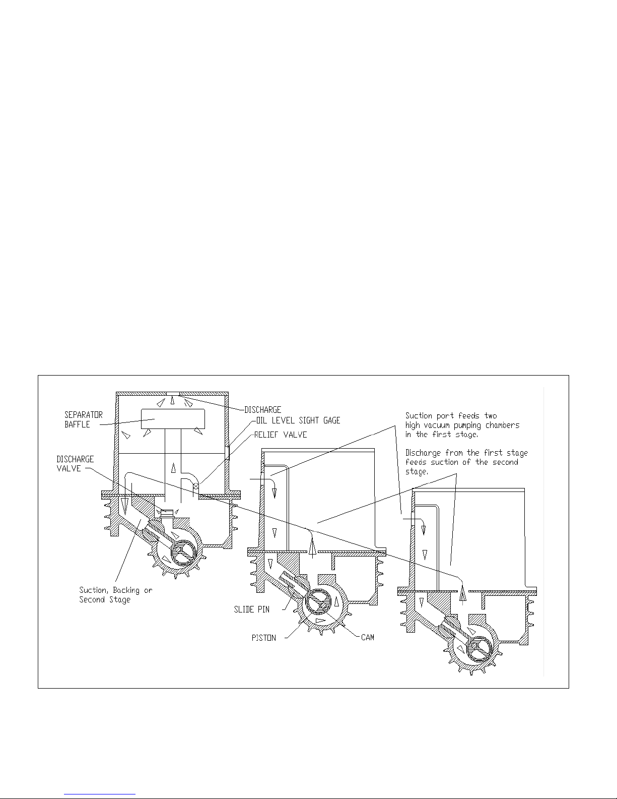
Figure 1. Operating Cycle
6
Operating Cycle
Gas from the system enters the pump suction and passes through the hollow piston slide and out into the space
being created between the piston and cylinder wall. This space increases and more gas is drawn in as the piston
rotates. At the same time, the gas taken in and trapped on the previous revolution is discharged into the inlet of the
backing stage.
The high vacuum pumping cycle is repeated in the backing stage. The gas is compressed and forced out through
the discharge valves along with a small amount of oil, and then into the oil separator where oil is separated from the
gas. This gas is discharged into the atmosphere and the oil drains back to the oil reservoir. Oil from the reservoir
does not normally enter the pump when stopped under vacuum, however, stopping the pump under vacuum is not
recommended.
Sealing and Lubrication
The pump components are lubricated and sealed against backflow of gas by a film of oil, which fill the running
clearances. When the pump is in operation the cylindrical part of the piston almost touches the pump cylinder at a
line along the length of the piston. An effective wave of oil is pushed ahead of this moving line. Oil is also being
squeezed through the clearances of the other working parts. The seal and bearings are lubricated and washed by
the flow of intake oil. There are two oil reservoirs, one for each stage, and at the end of the compression stroke the
oil is forced out with the discharged gas and returned to their respective reservoirs.
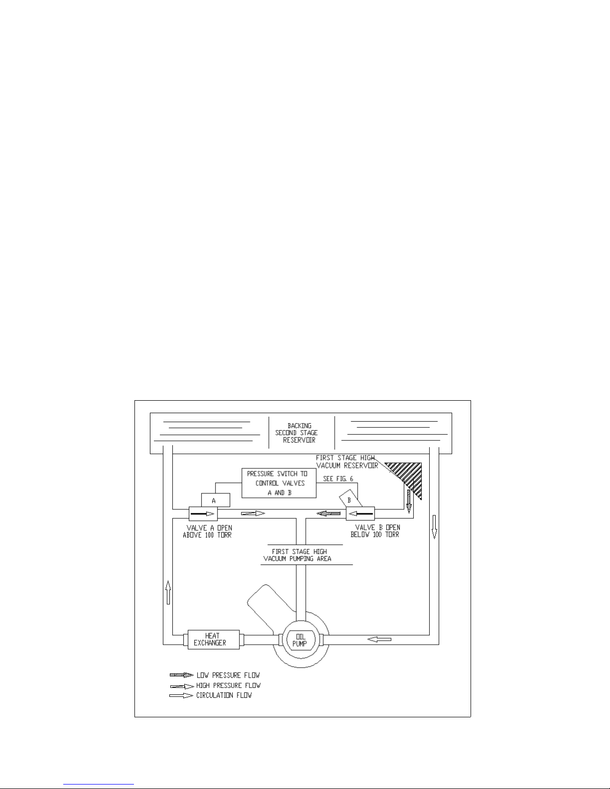
Figure 2 shows the oil flow for KTC-112 pumps. It circulates oil from the backing (second) stage reservoir through a
water-cooled heat exchanger and back to the reservoir. When the pump is at a pressure above 100 Torr, some of
the oil leaving the heat exchanger is admitted through solenoid valve (A) into the high vacuum (first) stage via the
bearing located on the non-drive side of the pump. Below 50 Torr, the pressure switch closed solenoid valve (A) and
opens solenoid valve (B) and the high vacuum (first) stage is then supplied with degassed oil from the first stage
reservoir. The oil supply pressure is provided by interstate pressure and the reservoir oil head. A solenoid valve
located on the drive side of the pump, which is open when the pump is running controls oil to the backing (second)
stage. Oil is delivered into the backing stage by differential pressure.
On the KTC-60, there is no oil pump, heat exchanger, or pressure switch. Oil is fed from the backing stage reservoir
to the drive-end of the pump, and from the high vacuum reservoir to the non-drive end of the pump. Solenoid valves
close both lines when the pump is stopped.
Figure 2. Oil Flow KTC 112
7

INSTALLATION
Vibramounts
KTC pumps are supplied with vibramounts that enable them to run quietly and vibration free. The pump can be
operated on any floor that will support its weight. The pump must be installed on the vibramounts and flexible
connectors fitted in suction, discharge, water and electrical connections. It is not necessary to bolt the pump to the
floor.
Bolt the vibramounts to the four holes in the feet. On the KTC-112 all four vibramounts are the same. On the KTC-60,
install two green vibramounts at the beltguard end and two red vibramounts at the other end.
Care must be taken to set the pump down squarely on the mounts when installing the pump in operating position.
Suction Manifolding
Inlet manifolding should be sized and designed with three objectives in mind:
1) To avoid gas flow restrictions
2) To prevent pump fluids from entering the process chamber
3) To protect the pump from the ingestion of particulate matter
Under normal conditions, the diameter of the manifolding should not be less that the diameter of the pump
connection and the pipe length should be kept to a minimum.
Oil may splash from inside the pump through the suction port. Therefore, the suction line must be designed to
prevent oil from collecting there, and draining back to the system or process.
A flexible connection should be installed in the suction manifold to provide freedom for the vibramounts. The vacuum
piping must be well aligned with the pump connections as not to place a strain on the piping.
Provisions for gauge installation and any other drilling in the piping must be made prior to piping installation;
otherwise, drilling particles entering the piping could be entrained into the pump.
A vacuum isolation valve should be installed adjacent to the suction port to be used for leak checking, shutting down
the system, or blanking off the pump.
Before connection the suction manifolding, distribute 4 quarts of oil over the two high vacuum slide pins. This will
necessitate reaching through the suction port with a container and pouring oil directly onto the slide pins. Then rotate
the pump by hand a minimum of two revolutions to distribute the oil throughout the pump interior.
Discharge Manifolding
During the initial operation and as long thereafter as necessary, a fine mesh screen should be installed across the
inlet connection to prevent abrasive or solid particles left in the line from being sucked into the pump. This screen
can be removed when particles no longer accumulate. If particles continue to accumulate, a filter should be installed
in the line.
Discharge manifolding should be sized and designed to prevent the following:
A. Return of oil mist condensate to the pump
B. Oil loss
C. Oil mist in the discharged gas
Under the normal conditions, the diameter of the manifolding should not be less than the diameter of the pump
connection and the pipe length should be kept to a minimum.
The installation of a Kinney oil mist eliminator on the discharge is recommended for all applications. Oil that collects in
the eliminator should be returned to the pump. The optional oil return kit will allow oil to drain back into the separator
housing when the pump is operating a low pressure or when the pump is stopped. If the pump is to operate
continuously, or normal operating pressure is 10 Torr or higher consult Kinney for special recommendations on oil
return.
It may be necessary to pipe the pump exhaust fumes away from the pump area, such as out of doors. If this is done,
the piping must be arranged to prevent line condensation from returning to the pump. A flexible connector should be
fitted in the discharge line to provide freedom for the vibramounts.
Cooling Water
The KTC-60 is air-cooled and does not require cooling water.
On the KTC-112 the lubricating oil is cooled by a shell and tube heat exchanger mounted adjacent to the oil pump on
the KTC-112.
DO NOT ALLOW THE COOLING WATER TO FREEZE IN THE HEAT EXCHANGER.
Connect a water supply line with “on-off” valve to the water inlet, and an open drain to air the water outlet. The inlet
8
 Loading...