

KINNEY KT SERIES, KT-300, T-150, KT-500, KT-850 Installation Operation Maintenance Repair Manual
Manual 1843-1
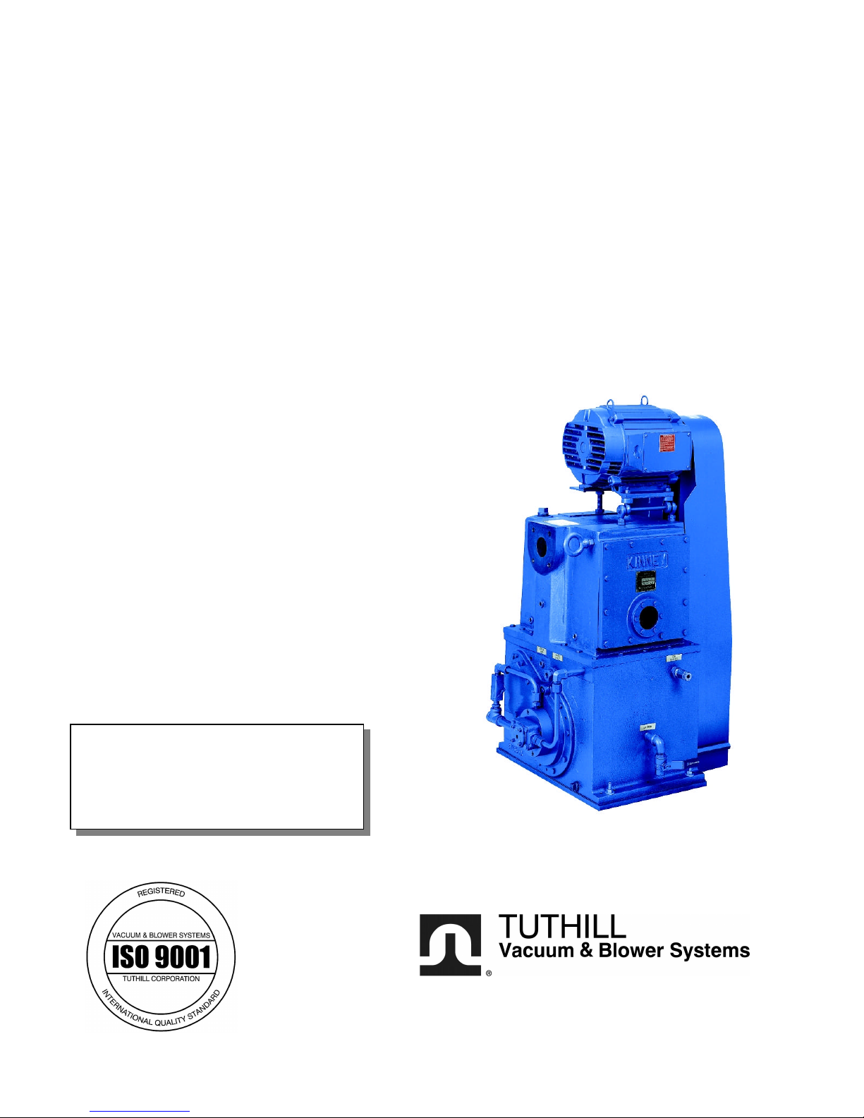
KINNEY® KT™ SERIES
Single Stage, Triplex Rotary Piston Pumps
Models
KT-150 KT-300 KT-500 KT-850
INSTALLATION
OPERATION
MAINTENANCE
REPAIR
MANUAL
WARNING
DO NOT OPERATE BEFORE
READING MANUAL.
06/2003
ADVANCING THE STANDARDS IN VACUUM TECHNOLOGY
4840 West Kearney Street
Springfield, Missouri USA 65803-8702
Tel 417 865-8715 800 825-6937 Fax 417 865-0307
E-mail: kinney@tuthill.com
http://vacuum.tuthill.com
! WARNING
DO NOT OPERATE
WITHOUT BELT
GUARD
809762-A000
The above safety instruction tags were permanently affixed to
your pump prior to shipment. Do not remove, paint over or
obscure in any manner.
Failure to heed these warnings could result in serious bodily
injury to the personnel operating and maintaining this
OPERATING PUMP. ENSURE ADEQUATE
REFER TO MANUAL SAFETY INSTRUCTIONS.
NOTICE
! CAUTION
DO NOT VALVE OR RESTRICT PUMP
DISCHARGE OPENING.
USE OIL MIST ELIMINATOR WHEN
VENTILATION WHEN DISCHARGING
INDOORS.
SAFETY PRECAUTIONS FOR ROTARY PISTON PUMPS
Please read the following safety information on this page before operating your vacuum pump.
• Do not operate the pump without the belt guard properly attached. Disconnect the pump motor from the electrical
supply at the main disconnect before removing the belt guard. Replace the belt guard before reconnecting the
power supply to the pump motor. Operating the pump without the belt guard properly installed exposes personnel
in the vicinity of the pump to risk from rotating drive components.
• Do not operate the pump with oxygen-enriched gas (greater than 20% by volume) in the suction line, unless the
pump has been prepared with an inert fluid suitable for the application.
Pumping oxygen-enriched gases with mineral oil or other non-inert fluids can cause fire or explosion in the
pump, resulting in damage or serious bodily injury.
• Take precautions to avoid prolonged or excessive exposure to oil mist or process materials emanating from the
discharge of the pump.
• Do not allow the pump to discharge into a closed, or inadequately ventilated room. Always use a discharge oil mist
eliminator unless the pump discharge is discharged to outside atmosphere. Laws and ordinances may pertain to
your local area regarding discharge of oil mist or vapor to atmosphere. Check local laws and ordinances prior to
operation of the pump with discharge to outside atmosphere. Venting of the discharge of an oil mist eliminator to
outside atmosphere is highly recommended.
• Do not restrict the pump discharge in any way, or place valves in the discharge line. The vacuum pump is a
compressor and will generate high pressures without stalling the motor when operated at low suction pressures.
Excessive pressure could cause damage or serious bodily injury.
• Disconnect the pump motor from the electrical supply at the main disconnect before disassembling or servicing
the pump. Make sure pump is completely reassembled, the belt guard is properly installed, and that all fill and
drain valves are installed and closed before reconnecting the power supply. Accidental starting or operation of
the pump while maintenance is in progress could cause damage or serious bodily injury.
• Lift pump only by the lifting lugs supplied with the pump. DO NOT lift equipment attached to pump by the pump
lifting lugs.
• Do not touch hot surfaces on the pump. In normal operation at low pressures, surface temperatures will not
normally exceed 180° F (82° C). Prolonged operation at 200 Torr (267 mbar a) may cause surface temperatures as
high as 220° F (104° C)
2

SECTION
TABLE OF CONTENTS
SAFETY PRECAUTIONS AND WARNINGS 2
INTRODUCTION 4
DESCRIPTION
Specifications 5
Description 6
INSTALLATION
Installing the Vibramounts 7
Suction Manifolding 8
Proper Venting 9
Discharge Manifolding 9
Cooling Water 9
Filling the Pump with Oil 11
Vacuum Gauges 12
Electrical Connections 12
OPERATION
General 12
Prestart Checks 12
Starting The Pump 13
Stopping The Pump 13
Handling Large Quantities of Water 13
Gas Ballast 14
MAINTENANCE
General 14
Periodic Maintenance 14
Oil Contamination 14
Changing the Oil 15
Lubricating the Pump 15
Stalling 16
Pump Leaks 16
Checking Pump Performance 16
Checking Process Equipment 16
Discharging Valves 17
Shaft-Seal Assembly 19
V-Belt Drive 19
DISASSEMBLY 20
ASSEMBLY 20-21
Replacement Parts 22
Recommended Oil 22
Troubleshooting Chart 23
Parts List & Exploded Views 24-29
WARRANTY STATEMENT 30
3

INTRODUCTION
CONGRATULATIONS on your purchase of a new KINNEY
Pump from Tuthill Vacuum & Blower Systems. Please examine the pump for shipping damage, and if any damage is
found, report it immediately to the carrier. If the pump is to be installed at a later date make sure it is stored in a
clean, dry location and rotated regularly. Make sure covers are kept on all openings. If pump is stored outdoors be
sure to protect it from weather and corrosion.
KINNEY KT vacuum pumps are built to exacting standards and if properly installed and maintained will provide
many years of reliable service. We urge you to take time to read and follow every step of these instructions when
installing and maintaining your pump. We have tried to make these instructions as straightforward as possible. We
realize getting any new piece of equipment up and running in as little time as possible is imperative to production.
WARNING: Serious injury can result from operating or repairing this machine without first reading the service
manual and taking adequate safety precautions.
IMPORTANT: Record the pump model and serial numbers in the OPERATING DATA form below. You will save
time and expense by including this reference identification on any replacement part orders, or if you require service
or application assistance.
®
KT™ Single-Stage, Tri-plex Rotary Piston Vacuum
OPERATING DATA
It is to the user’s advantage to have the requested data filled in below and available in the event a problem
should develop in the blower or the system. This information is also helpful when ordering spare parts.
Model No. __________________________________ V-Belt Size ______________ Length _____________
Serial No. __________________________________ Type of Lubrication:
(Recorded from nameplate on unit) _____________________________
Startup Date ________________________________ ________________________
Pump RPM ________________________________ Operating Vacuum ____________________________
Pump Sheave Diameter ______________________ Any other special accessories supplied or in use:
Motor Sheave Diameter _______________________
Motor RPM _______________ HP ______________ ___________________________________________
NOTES:
4

KINNEY® KT™ SERIES MANUAL 1843-1
© 2003, Tuthill Corporation
INTRODUCTION
This manual applies to Kinney Vacuum models KT-150, KT-300, KT-500 and KT-850. You should be thoroughly
familiar with these instructions before attempting to install, operate or repair this unit. Consult Tuthill Vacuum &
Blower Systems when problems arise that cannot be resolved after reading this manual. Always include pump
nameplate information when ordering parts or components.
SPECIFICATIONS
KT-150 KT-300 KT-500 KT-850
Free Air
Displacement
Pump Speed (rpm) RPM 1055 870 721 581
Motor speed at 50
Hz
Motor speed at 60
Hz
Motor Power HP 7.5 15 30 40
Oil Capacity (total/
refill)
Cooling water at
60° F (16° C)
Cooling Water Inlet Inch
Suction, 150 lb.
ANSI Flanged
Discharge, 150 lb.
ANSI Flanged
CFM
m³/h
RPM 1,500 1,500 1,500 1,500
RPM 1,800 1,800 1,800 1,800
US gal.
Liters
Gpm
L/min
NPT
3 4 6 8
2 3 4 5
150
255
6/5
23/19
1/4 1.5/6 2.5/9 3.5/13
1/4” 3/8” 3/8” 3/8”
300
510
10/8.5
38/32
490
840
15/12.5
57/47
780
1325
28/25
106/95
Height w/o oil mist
eliminator
Floor Space Inches
Weight Lbs
Ultimate
Pressure
Noise Level
(Typical at 10 Torr)
Inches
mm
mm
Kg
Microns 10 10 10 10
dBA 71 72 73 75
43
1092
24x26
609x660
800
363
51
1295
27x34
686x864
1,525
692
63
1600
34x38
864x965
2,625
1,191
71
1803
38x49
965x1245
4,175
1,894
5
Description
The KT-Series pumps covered herein have an oil circulating pump to provide adequate lubrication at all pressures
including atmosphere. The vacuum pump has three cams and pistons pumping in parallel, driven by a common
shaft. The cams are positioned on the shaft so as to dynamically balance moving parts. This balancing technique
applied to the Rotary Piston Principle was developed by Tuthill Vacuum & Blower Systems and virtually eliminated
vibration.
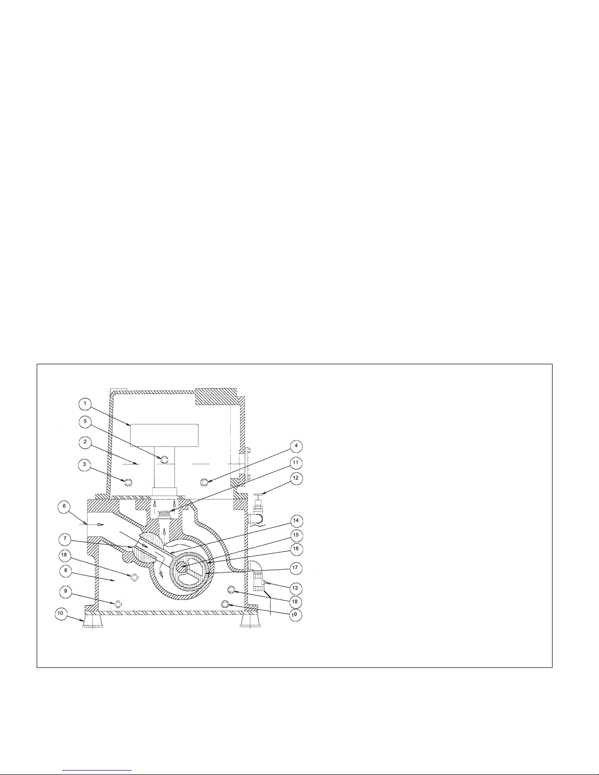
Figure 1. shows a cross section of the pump with the pistons being driven by the cams and revolving within the
cylinder.
Gas is drawn into the pump through a common inlet, channeled to the three piston slides and into the space behind
the pistons as they rotate. The gas ahead of the pistons is compressed and forced out the discharge valves. As the
gas is forced through the pump, sealing oil is mixed with the discharged gas and the discharged mixture is
channeled into the separator, which is located in the reservoir, and there the gas is separated from the oil. Sealing
and lubricating oil is provided by the oil pump which is mounted on the non-drive ahead and driven by direct
coupling to the vacuum pump drive shaft. The oil pump provides forced feed oil circulation at all operating pressures
including atmosphere.
All models have a channeled drive shaft with an opening at each cam to distribute oil through the pump.
Oil is taken from the reservoir at a point some distance above the reservoir bottom. This provides an area for
impurities to collect for draining.
Figure 1. Cross Section of KT Series Vacuum Pump
Key to Figure 1.
1. Air/Oil Separator
2. Oil Level
3. Connection for optional
temperature switch
4. Connection for optional temperature gauge
5. Connection for “scum” take-off
6. Pump Inlet
7. Slide Pin
8. Water cooling jacket
9. (Far Side) Cooling Jacket drain 1 of 2
10. Mounting Pads
11. Discharge Valve
12. Gas Ballast Valve
13. Oil Drain
14. Piston Slide
15. Shaft
16. Piston
17. Cam
18. Connection for optional heater
19. Cooling jacket drain 2 of 2
6
INSTALLATION
General
Installing the Vibramounts
KT pumps are supplied with vibramounts (vibrasprings on the KT-850) which enable them to run quietly and
vibration free. The pump can be operated on any floor which will support its weight. The pump must be installed on
the vibramounts and flexible connectors fitted in suction, discharge, water and electrical connections. It is not
necessary to bolt the pump to the floor.
If the studs are not already installed into the vibramounts, thread the short end into the top of the mount (smaller
diameter) up to the spacer portion of the stud.
The vibramount attachment holes are the four open threaded holes in the flanged edges of the cylinder, in line with
the bottom plate/cylinder bolts, just in from each corner of the pump.
DO NOT USE THE FOUR UNTHREADED HOLES WHICH ARE USED FOR SHIPMENT ONLY.
With the pump lifted off the ground, thread the vibramounts with studs into the vibramount attachment holes until
contact is made between the top of the vibramount and the cylinder bottom plate, and the foot location is parallel to
the pump shaft.
Care must be taken to set the pump down squarely on the mounts when installing the pump in operating position.
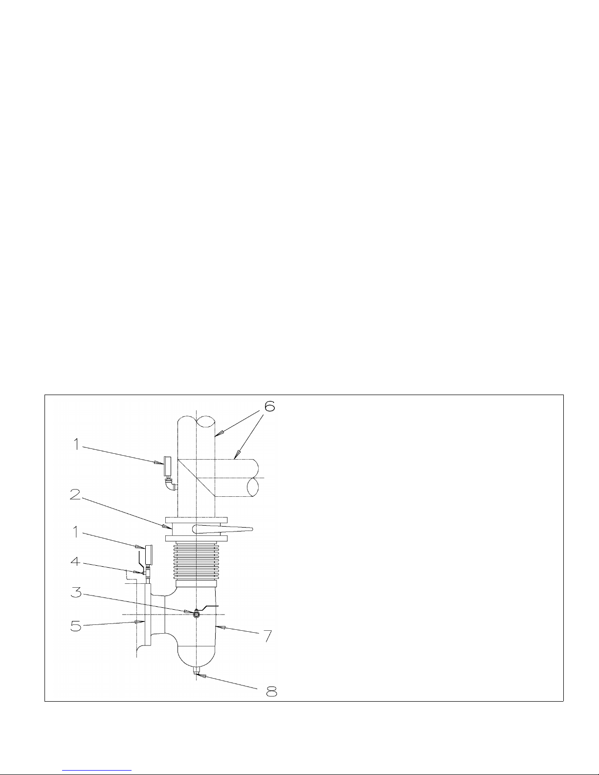
Figure 2. Detailed Manifold Arrangement
Key to Figure 2.
1. Vacuum Gauge
2. Isolation Valve
3. Air Vent Valve
4. Shut Off Valve
5. Pump Suction Flange
6. To System
7. Right angle flexible connector
8. Trap drain
7
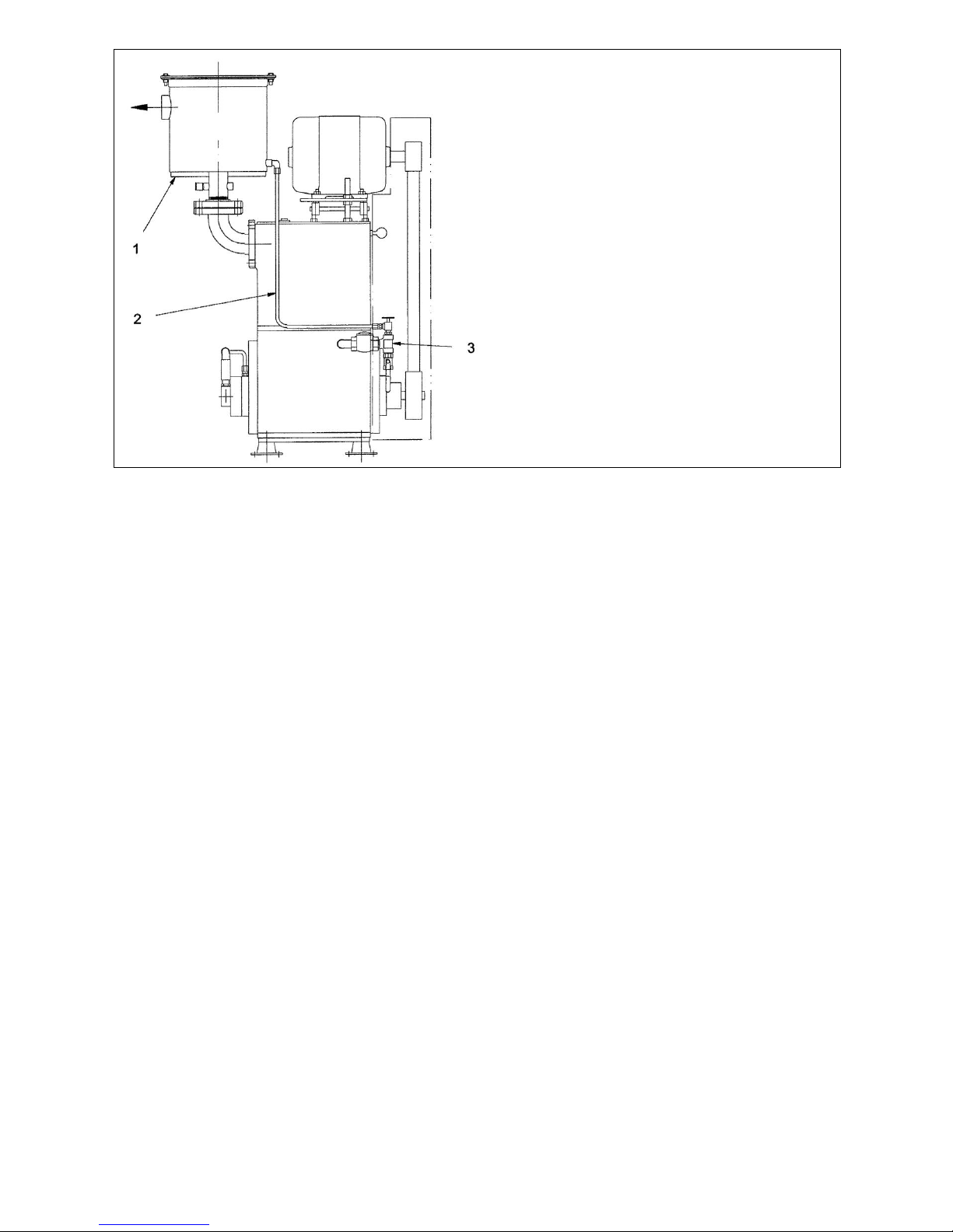
Key to Figure 3.
1. Oil Mist Eliminator
2. Oil Return Line
3. Gas Ballast Assembly
(standard arrangement)
Figure 3. Oil Return to the Gas Ballast Valve
Suction Manifolding
Inlet manifolding should be sized and designed with four objectives in mind:
A. To avoid gas flow restrictions.
B. To prevent pump fluids from entering the process chamber.
C. To protect the pump from the ingestion of particulate matter.
D. To allow proper venting of the pump and suction manifold.
Under the normal conditions, the diameter of the manifolding should not be less than the diameter of the pump
connection and the pipe length should be kept to a minimum.
Oil may splash from inside the pump through the suction port so the suction line must be designed to prevent oil
from collecting there and draining back to the system or process. See Figure 2 for recommended arrangements as
a guide for fabricating inlet manifolding.
A flexible connection should be installed in the suction manifold to provide freedom for vibramounts. The vacuum
piping must be well aligned with the pump connections so as not to place a strain on the piping.
Provisions for gauge installation and any other drilling in the piping must be made prior to piping installation,
otherwise, drilling particles entering the piping could be entrained into the pump. A vacuum isolation valve should be
installed adjacent to the suction port to be used for leak checking, shutting down the system, or blanking off the
pump.
Before connecting the suction manifolding, distribute 4 quarts of oil over the three slide pins. This will necessitate
reaching through the suction port with a container and pouring oil directly onto the slide pins. Then rotate the pump
by hand a minimum of two revolutions to distribute the oil throughout the pump interior.
During the initial operation and as long thereafter as necessary, a fine mesh screen should be installed across the
inlet connection to prevent abrasive or solid particles left in the line from being sucked into the pump. This screen
can be removed when particles no longer accumulate. If particles continue to accumulate, a filter should be installed
in the line.
8

Proper Venting
The Vacuum pump must be properly vented to ensure all oil is removed from the pumping chamber before the
pump is turned off. Also, the suction line must be properly vented to ensure oil does not migrate into the process
chamber.
Recommended vent valve sizes:
KT-150 .75 inch
KT-300 1.0 inch
KT-500 1.5 inches
KT-850 2.0 inches
The vent valve must be open for at least 10 seconds before the pump is turned off to remove all oil from the pumping
chamber.
Discharge Manifolding
Discharge manifolding should be sized and designed to prevent the following:
A. Return of oil mist condensate to the pump
B. Oil loss
C. Oil mist in the discharged gas.
Under the normal conditions, the diameter of the manifolding should not be less than the diameter of the pump
connection and pipe length should be kept to a minimum.
The installation of a Kinney oil mist eliminator on the discharge is recommended for all applications, (as shown in
Figure 4). Oil which collects in the eliminator should be returned to the pump. The optional oil return kit will drain
allow oil to back into the separator housing when the pump is operating at low pressure or when the pump is
stopped. If the pump is to operate continuously, or normal operating pressure is between 10 torr (13 mbar) and 150
torr (200 mbar), the oil return should be connected to the gas ballast as shown in Figure 3. Over 150 torr (200 mbar)
the oil return should be connected to the pump inlet.
It may be necessary to pipe the pump exhaust fumes away from the pump area, such as outdoors. If this is done,
the piping must be arranged to prevent line condensation from returning to the pump. A flexible connector should be
fitted in the discharge line to provide freedom for the vibramounts.
Cooling Water
The cylinder cooling water jacket is shipped dry, with the drain plugs removed. They are tied to the pump in a small
cloth bag. Replace the plugs in the positions shown in Figure 1 and fill the water jacket before starting the pump.
If an optional water flow modulating valve (Water Miser) is fitted, the cylinder may take 20 minutes or more to fill. The
delay can be avoided by lifting the spring to open the valve. For installation of the valve see Figure 6.
Failure to ensure that the cooling water jacket is filled before starting the pump will result in localized over-heating of
the pump and cause extensive damage.
For installations requiring starting at ambient temperatures lower than 60°F (16°C), electric heaters should be
installed in the water jacket. (See Figure 5.)
9
Key to Figure 4.
1. Discharge connection
2. Relief Valve
3. Top cover gasket
4. Element
5. Oil Drain Connection
6. Optional oil drain line
kit
7. Oil Return connection
Figure 4. Oil Mist Eliminator
DO NOT ALLOW THE COOLING WATER TO FREEZE IN THE PUMP.
Freezing of the cooling water jacket usually results in extensive damage to the pump cylinder which cannot be repaired.
Connect a water supply line with “on-off” valve to the water inlet, and an open drain to the water outlet. The inlet
line should have a flow regulating valve. If the water supply unreliable, it is advisable to install a flow switch to stop
the pump or signal when the flow is interrupted. Normally the cooling water will be off when the pump is not running.
A water pressure relief valve is fitted in the water jacket. This relief valve is set to open at 50 PSIG (3.5 bar).
Standard cooling water rates are for up to 80°F (26°C) supply temperature and operation within the design continuous operating pressure range of .1 to 100 Torr (.13-130 mbar a). Sustained operation above 100 torr (130
mbar) and/or long pump downs generally require larger cooling water flow rate and/or external oil heat exchanger.
Larger cooling water rate increases cooling efficiency reduces heat dissipation to room and keeps oil cooler
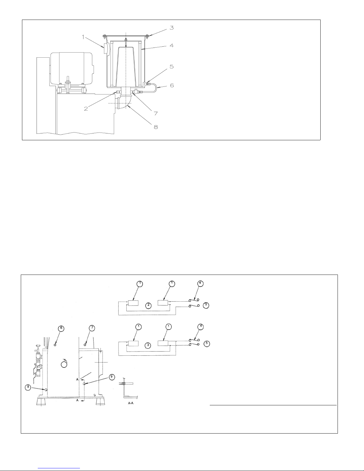
Key to Figure 5.
1. Heaters
2. For 460 volts
3. For 430 volts
4. Switch
5. Input (fuse protected)
6. Temperature Gauge
7. Optional temperature switch
8. Install (1) heater into ¾ NPT tap far side (½
NPT on KT150, 300)
9. Install (1) heater into ¾ NPT tap this side (½
NPT on KT150, 300)
Before energizing heaters:
1. Be sure water jacket is filled.
2. Turn off cooling water supply.
3. Do not restrict cooling water outlet.
Pump Heaters P/N
KT-150 (2) 300W 074501-0000
KT-300 (2) 500W 074502-0000
KT-500 (2) 750W 074503-0000
KT-850 (2) 1000W 074504-0000
Figure 5. Water Jacket Heater Installation
10
 Loading...