

Kingyoung M1525BF Installation Manual
INSTALLATION GUIDE
1
2
To loose two hex head cap screws at the front panel.
To loose two chassis screws on the rear panel from the case.
Specifications are for reference only and subject to change without notice.
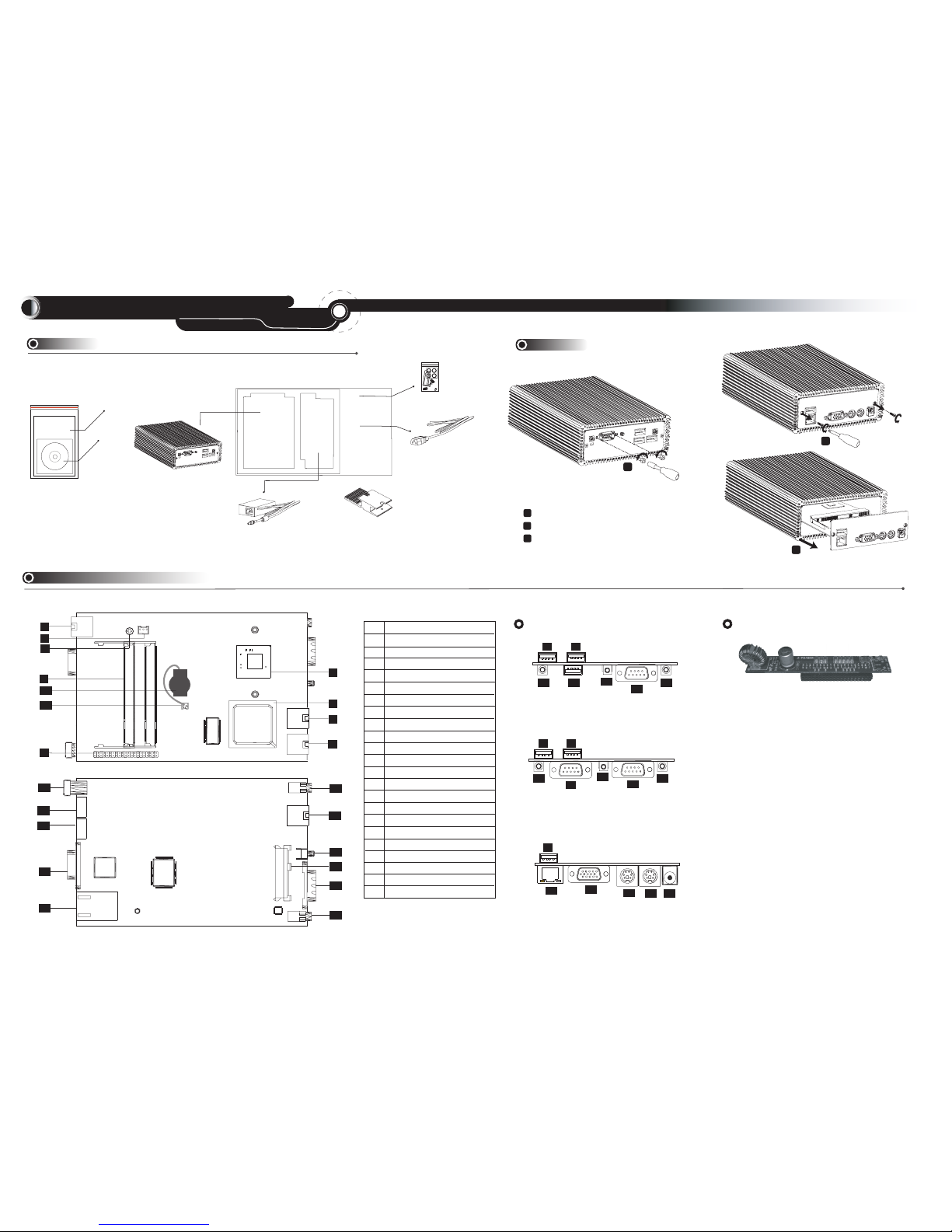
Mainboard and Optional Daughter Boards' Layout
M1525BF
Item Checklist
Installation
Guide
Installation Guide
Driver CD
Accessories Pack
Power Adapter
Power Cord
System Unit
A1 ATOM D525 CPU
A1 ATOM D525 CPU
A2 Intel ICH8M chip
A2 Intel ICH8M chip
A3 Front USB port
A3 Front USB port
A4 Front USB port
A4 Front USB port
A5 Wide range power adapter slot
A5 Wide range power adapter slot
A6 Rear USB port
A6 Rear USB port
A7 CPU cooling fan connector
A7 CPU cooling fan connector
A8 HDD Screw
A8 HDD Screw
A9 DDR3 SODIMM slots
A9 DDR3 SODIMM slots
A10 CMOS battery
A10 CMOS battery
A11 Battery connector
A11 Battery connector
A12 Line-out phone jack
A12 Line-out phone jack
A13 Front USB port
A13 Front USB port
A14 Power button
A14 Power button
A15 SATA HDD/SDD connector
A15 SATA HDD/SDD connector
A16 Primary COM port
A16 Primary COM port
A17 Mic-in phone jack
A17 Mic-in phone jack
A18 DC 10 ~ 26V power input
A18 DC 10 ~ 26V power input
A19 PS/2 mouse port
A19 PS/2 mouse port
A20 PS/2 keyboard port
A20 PS/2 keyboard port
A21 VGA port
A21 VGA port
A22 GigaLAN port
A22 GigaLAN port
B1 Optional secondary COM port
B1 Optional secondary COM port
A1
A2
A3
A4
A6
A7
A5
A12
A14
A15
A16
A17
A13
A18
A19
A22
A20
A16
A18
A19
A21
A22
A6
A4 A3
A15
A14
A12
A11
A10
3
Pull out the mainboard from the case.
Wide range power adapter
S525BF front panel IO port alignment
B1
S525BSF front panel dual COM ports alignment
S525BF/S525BSF rear panel IO port alignment
A4 A3
A10
A12
A14
A15
A8
A21
SILICONE HEA
T
T
S
INK
P
AS
T
SIL
ICONE HEA
T
ASTE
AS
Barebone Unit Unpacking
A9
1
1
1
2
1
3
A10
A11
CPU Heat Sink
premounted on the CPU
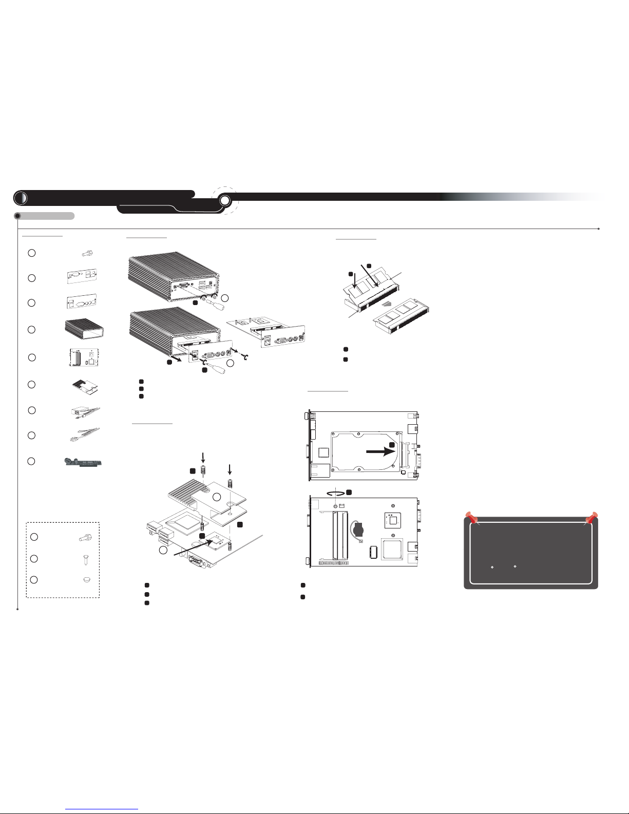
Part List
STEP 1
Case Screws * 2
Rubber Stand * 4
K
STEP 2
Installing Memory
STEP 3
Installing CPU Heatsink
CPU Heatsink premounted on the CPU, it is unnecessary to remove
or reinstall heatsink unless maintaining or repair.
WARNING
M1525BF
Accessories Pack
A
B
C
D
E
COM/DVI Hex Head
Cap Screws (* 4)
Front Panel
Rear Panel
Case
INSTALLATION GUIDE
Mainboard
F
CPU Heat sink,
with a Cooper at
the buttom
Hardware Installation
Wide range
power adapter
This equipment has been tested and found to comply
with the limits for a Class B digital device, pursuant to
Part 15 of the FCC rules. These limits are designed to
provide reasonable protction against harmful interference
when the equipment is operated in a residential installation.
This equipment generates, uses, and can radiate radio frequency
energy and if not installed and used in accordance with
the instruction manual may cause harmful interference to radio
communications. However, there is no guarantee that
interference will not occur in a particular installation.
If this equipment does cause harmful interference to radio or
television reception, which can be determined by turning
the equipment off and on, the user is encouraged to try to correct
the interference by one or more of the following measures:
* Reorient or relocate the receiving antenna.
* Increase the separation between the equipment and receiver.
* Connect the equipment into an outlet on a circuit different from
that to which the receiver is connected.
* Consult the dealer or an experienced radio TV technician for help.
Notice: The changes or modifications not expressly approved
by the party responsible for compliance could void the user's
authority to operate the equivalent.
The system uses the chassis
for heat dissipation, so the
normal operating temperature
of chassis is between
50 C ~ 65 C.
Specification is subject to change without notice, it is for reference only.
HDD
Screw
The Reverse Side
The Front Side
Complete
1
2
Glue the heatsink compound on the CPU die surface.
1
2
Insert SO-DIMM into the SO-DIMM slot
on the motherboard by 30 .
0
Push down the SO-DIMM onto DIMM slot.
SO-DIMM
SO-DIMM Slot
2
1
H
Power Adapter
I
Power Cord
J
Unpacking (Installing) Motherboard from (to) the chassis
A
1
2
3
To loose (fasten) hex head cap screws at the front panel.
To loose (drive) two chssis screws at the rear panel.
Pull out (slide in) the motherboard from(into) the case.
STEP 4
Installing 2.5" SATA HDD or SSD
1
2
Insert 2.5" SATA HDD or SSD to the SATA connector on the reverse side
of mainboard.
Turnover the mainboard and drive the screw at the front side of mainboard
to fasten the HDD.
CPU Heatsink
Screws
2
Install CPU heat sink on the top of CPU.
Hex Head
Cap Screws * 2
( * 4 for S525BSF)
A
1
1
SATA 2.5" HDD or SSD
1
2
3
G
1
1
1
3
J
1
2
Paste
L
1
F
3
Tighten CPU heatsink with screws into pillaret.
 Loading...