


KWO1000
User Manual
Model:1003+1004
2018.0 2.0 2
Vers ion:1 .0

Contents
About this manual
Packing list
Brief introduction
Features
Mechanic information
Wireless HD Transmitter:1003
Wireless HD Receiver:1004
Interface information
Wireless HD Transmitter:1003
Wireless HD Receiver:1004
Installation instructions
Wireless HD Transmitter:1003
Wireless HD Receiver:1004
Product specifications
OLED Screen Description
Trouble Shooting
Notices Description
01
01
02
02
03
03
04
05
05
07
09
09
11
13
16
17
19
FORWORD
- Please read this manual carefully before using this product
and retain it properly for future reference.
- If there is any doubt or difficulty in the process of product usage,
please feel free to contact us or the dealer.
- The company reserves the authority to amend the specification.
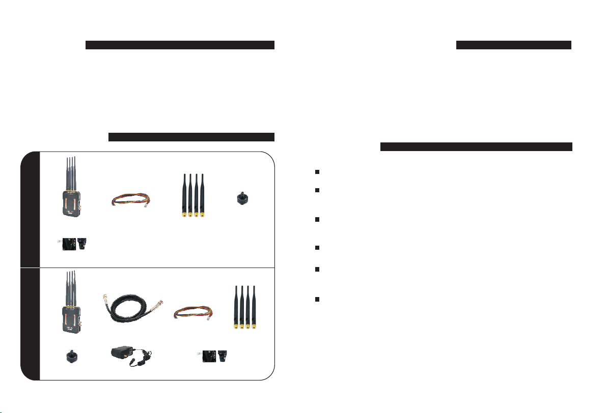
PACKING LIST
BRIEF INTRODUCTION
The wireless transmission system can help a variety of video
transmission platform to achieve easy to carry,install fast,real
zero-wiring,plug&play,change the traditional site wiring and
get rid of cumbersome cabling,enhanced video transmission
system Flexibility.
FEATURES
Wireless full HD video transmission;
TX: 1003 RX: 1004
TX:1003 * 1
RS232 cable * 1 Antenna*4
Double nut * 1
Min 50ms low latency enables no waiting for wonderful
image receiving;
Reliable overvoltage protection for better ensuring the safety
of power supply;
Supports both HDMI and SDI interfaces for video input/output;
V-mount
Full hardware design; plug & play; eliminates the hassle of
running wires, simple and convenient;
Transmission distance: up to 800 meters under the point-to-point
mode (with 5dBi antenna in open space).
RX:1004 * 1 SDI cable * 1 RS232 cable * 1 Antenna*4
Double nut * 1
01 02
Power Supply(12V/2A)* 1
V-mount
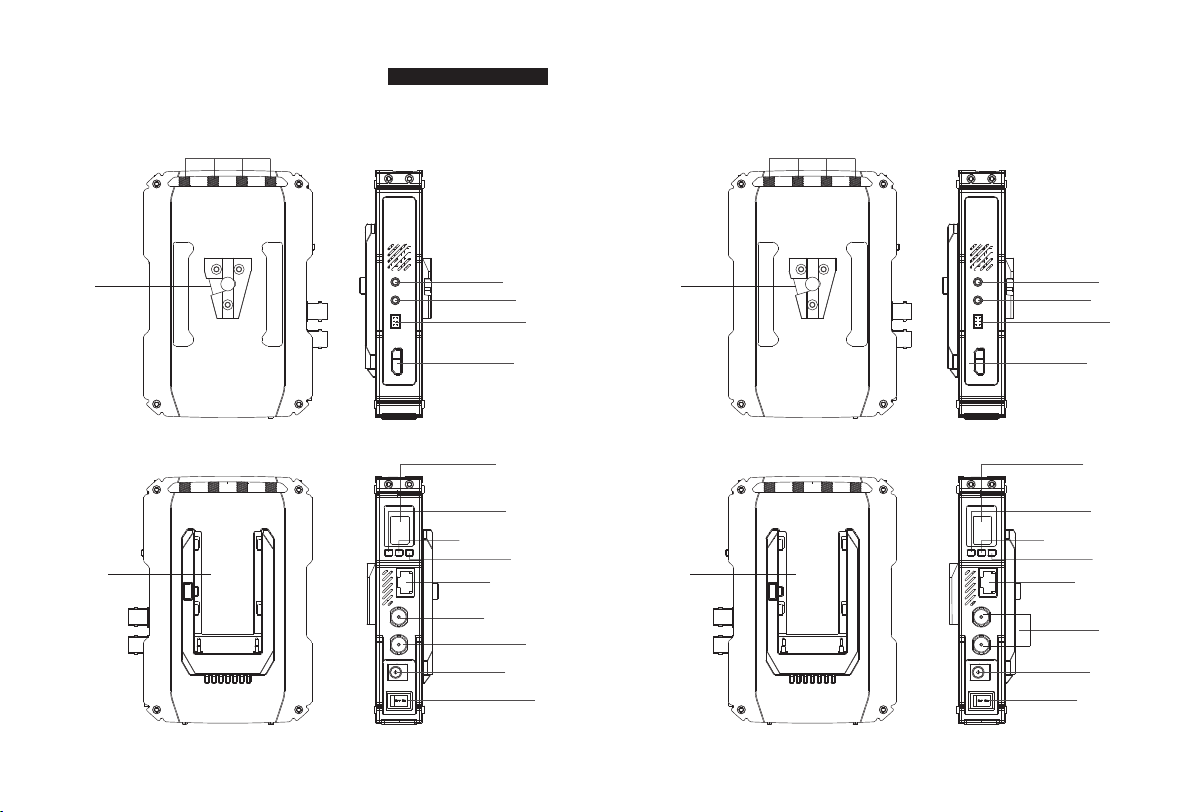
MECHANIC INFORMATION
TX:1003
V-MOUNT
SONY F-Type
Battery Plate
5.8G Antenna Interface
TALLY OUT
Audio IN
RS232
HDMI IN
OLED Screen
CH Button
Mode switch button
OK Button
LAN interface
SDI LOOP OUT
SDI IN
DC IN 12V
Power Switch
RX:1004
V-MOUNT
SONY F-Type
Battery Plate
5.8G Antenna Interface
TALLY IN
Audio out
RS232
HDMI OUT
OLED Screen
CH Button
Mode switch button
OK Button
LAN interface
SDI OUT
DC IN 12V
Power Switch
03 04

INTERFACE INFORMATION
TX:1003
MODE Button
1.
No. item Parameter Remark
MODE Button(SW2 )
3S long press
6S long press
2. CH Button
No. item Parameter Remark
CH Button(SW1 )
OK Button
3.
No. item Parameter Remark
OK Button
3S long press
Frequency witching
Switch RTSP and point-
to-point mode
Frequency witching
6S long press, WPS pairing
Valid only after
connected with RX
7. RS232
No.
1
2
3
4
5
6
8. HDMI IN
No.
1 3
2
456
item
NC NC
P12V
NC
TXD
GND
RXD
item
HDMI IN
Parameter
Default set with out
( reserved for 12V voltage output)
Data transmit TX
Data receive RX
Parameter
HD Video input
Remark
NC
GND
Remark
4. OLED Screen
No.
item
1. Signal Icon
2. Frequency Icon
network connections
Indicates current working frequency
5. Tally out: Output 5V power supply
Parameter
Remark
9. SDI LOOP OUT: SDI Loop output
10. SDI IN
No.
item
SDI IN
Video source input, if SDI and HDMI are
input at the same time, priority SDI input ,
if not input at the same time, which one is
first input, which one is preferred.
Parameter
Remark
6.
Audio in
No.
05 06
item
Audio in
External audio input and video source audio option,
Can not be superimposed on the audio,
use the function keys to switch
Parameter
Remark
11. DC IN: input power supply 12V/2A
12. LAN: External network port

RX:1004
1. MODE Button
No.
2.
CH Button
item
MODE Button
6S long press
No. item Parameter Remark
OK Button
3.
CH Button
3S long press
No. item Parameter Remark
OK Button
4. OLED Screen
No.
item
1. Signal Icon network connections
2. Frequency Icon
Indicates current working frequency
5. Tally in: low level input is valid
Audio out
6.
No.
item
Audio out
Parameter
Switch RTSP and pointto-point mode
Frequency witching
6S long press, WPS pairing
Parameter
Parameter
LINE OUT output and SDI/HDMI video
source audio output at the same time
Remark
Remark
Remark
7. RS232
1 3
2
No.
1
2
3
4
5
6
HDMI OUT
8.
No.
item
NC NC
P12V
NC
TXD
GND
RXD
( reserved for 12V voltage output)
item
HDMI OUT
Both the HDMI and the two SDI outputs simultaneously
9. SDI OUT
No.
item
SDI OUT
10. DC IN: input power supply 12V/2A
11. LAN: External network port
456
Parameter
Default set with out
NC
Data transmit TX
GND
Data receive RX
Parameter
Parameter
Video source output
Remark
Remark
Remark
07 08

INSTALLATION INSTRUCTIONS
TX: 1003
1. Install four 5dBi antennas on the transmitter
install antennas
2. Connect transmitter to 12V Power-supply and turn on the power button,
OLED screen lighted up, the Signal and Frequency icons display,
Finished Starting-up )
4. For Transmitter inputs, either HDMI or SDI works, when the input is
SDI source, the SDI loop output(for local monitoring) is enabled."VIDEO"
icon will and only will display in OLED when a video input is properly
connected.
09
Note: When transmitter 1003 SDI output, the SDI output can only be used
if SDI under loop output.
4. Audio input, transmitter 1003 connected to the microphone,
(MODE key press 3S can switch the internal and external sound).
Connect the microphone
SDI monitor
SDI loop output
POO3
HD Player
HDMI
HDMI Cable
HDMI
12V power supply
SDI cable
connect
Camera
10

RX:1004
1. Install four 5dBi antennas on the receiver
install antennas
2. Connect transmitter to 12V Power-supply and turn on the power button,
OLED screen lighted up, the Signal and Frequency icons display,
Finished Starting-up )
3. For Receiver outputs, all HDMI/SDI interface can output synchronously.
The Signal icon shows as a "X" in OLED when network between Transmitter
and Receiver disconnected or connecting; the Signal icon display properly
when network connected."VIDEO" icon will and only will display on OLED
when the video works properly.
4. Audio output, receiver 1004 connected to the audio output.
HDMI
TV
HDMI Cable
SDI cable
connect
HDMI
SDI monitor
SDI cable
connect
12V power supply
11 12

PRODUCT SPECIFICATIONS
TX: 1003
Operating
Frequency
Antenna Mode 4*4 5dBi External antenna
Modulation Mode
Transmission power
EVM
Receiving Sensitivity
Bandwidth
Wireless Protocol
Network encryption
Network Mode
Transmission Distance
Transmission Delay
TX : 1003
Transmission Rate
Pairing Function
Frequency Hopping
HDMI Protocol
Video Resolution
Audio Format
Video
Compression Format
External Audio
IO port signal return
Interface
Operating Power Supply
Overvoltage
Protection Range
Power Consumption
5190MHz,5230 MHz,5270 MHz,5310 MHz,5510 MHz,5550 MHz,
5590 MHz,5630 MHz,5670 MHz,5755 MHz,5795 Mhz
OFDM
17dBm
≤-28dB
≤-70dBm
40MHz
802.11n
WPA2/WPS
point-to-point private protocol, RTSP protocol
point-to-point Up to 800m LOS,
50ms(min)
Max 300Mbps
Support
Manual
Support HDMI 1.3
1080p 1080i 720p 576p,576i,480p,480i(up to 1080P/60Hz ), , ,
PCM
H.264
Support line-in audio input
Support Tally signal return
Standard HDMI input*1, SDI port*2 (1 input, 1 Loop Through),
232 interface*1, DC 5.5 power supply input*1,
CH button*1, MODE OLED*1, OK button*1,
LINE IN*1 , RJ45 interface *1, Tally socket*1,
DC12V / 2A (with Part 6677 )
7-17V
8-12W
Operating
Frequency
Antenna Mode 4*4 5dBi External antenna
Modulation Mode
Transmission power
EVM
Receiving Sensitivity
Bandwidth
Wireless Protocol
Network encryption
Network Mode
Transmission Distance
Transmission Delay
RX : 1004
Transmission Rate
Pairing Function
Frequency Hopping
HDMI Protocol
Video Resolution
Audio Format
Video
Compression Format
External Audio
IO port signal return
Interface
Operating Power
Supply
Overvoltage
Protection Range
Power Consumption
5190MHz,5230 MHz,5270 MHz,5310 MHz,5510 MHz,5550 MHz,
5590 MHz,5630 MHz,5670 MHz,5755 MHz,5795 Mhz
OFDM
17dBm
≤-28dB
≤-70dBm
40MHz
802.11n
WPA2/WPS
point-to-point private protocol
point-to-point Up to 800m LOS,
50ms(min)
Max 300Mbps
Support
Manual
Support HDMI 1.3
1080p 1080i 720p 576p,576i,480p,480i( ), , , up to 1080P/60Hz
PCM
H.264
Support line-in audio input
Support Tally signal return
Standard HDMI output*1, SDI output * 2 (2 channel simultaneous output),
power supply input*1, CH button*1, 232 interface*1
MODE OLED *1, OK button*1,RJ45 interface *1, Tally socket*1,
DC12V/2A
7-17V
7-9W
RX: 1004
13 14

OLED SCREEN
OLED SCREEN DESCRIPTION
1. AUDIO
item
Audio
Signal icon
Video
Mode
Frequency
2.Signal icon
VIDEO
3.VIDEO
4.Mode
RTSP
5630
OLED Screen Description
Audio display, display of the headphone icon table, external audio input,
No Audio input
(Blank)
Network connections
No Video input
(Blank)
Point to Point Transmitting
(Blank)
Indicates current working frequency
Video source connected successfully
( )VIDEO
(RTSP)
Video RTSP Streaming
5.Frequency
Remark
Model
TX:1003
Model
RX:1004
Icon
Signal icon
VIDEO
Mode
Frequency
Icon
Signal icon
VIDEO
Mode
Frequency
Indication
Contents
X
Signal bar
(Blank)
VIDEO
RTSP
(Blank)
5----
Indication
Contents
X
Signal bar
(Blank)
VIDEO
RTSP
(Blank)
5----
Status
Connecting
Network connection success
No Video input
Video source connected
successfully
Video RTSP Streaming
Point to Point Transmitting
Indicates current working
frequency
Status
Connecting
Network connection success
No Video input
Video source connected
successfully
Video RTSP Streaming
Point to Point Transmitting
Indicates current working
frequency
15 161718

TROUBLE SHOOTING
Troubles & Possible Reasons:
Displaying “Link Connecting...” for long time
Transmitter is not electrified.
Transmitter or receiver is not placed erectly.
The transmitter and receiver are too far away.
Several solid wall partition TX and RX.
There are too many obstacles between TX and RX.
Haven't matched the code of TX and RX.
There is other transmitter which is under working
condition near the receiver.
No Video Signal received
Transmitter and video source are not connected.
OSD Information on TV
The video source is turned OFF.
Video source were NOT switched to SDI/HDMI output.
Bad contact of cable of transmitter
Abnormal working of transmitter
Problem with cable between TX and video source
Player NOT support the output resolution format.
No signal input to Receiver or TV/Monitor
Receiver is turned OFF.
Receiver and TV are not connected.
TV/Monitor NOT switched to SDI/HDMI input.
Bad contact of the cable of receiver or TV/monitor
TV/Monitor turn into standby mode
Image
Abnormal working of receiver.
No image appear on TV/Monitor
Bad contact of receiver or cable.
Abnormal working of receiver
Receiver failure
Solutions:
Power on transmitter.
Place the TX or RX onto the base and replace them erectly.
Move the receiver closer to the transmitter.
Reduce the number of solid walls between TX and RX.
Move the receiver closer to the transmitter.
Rematch the code of transmitter and receiver.
Power off other independent transmitter, place the
receiver away from the other sources of interference.
Connect the transmitter to video source by SDI/HDMI cable.
Power ON the video source.
Switch the Video source to SDI/HDMI output.
Remove and then re-plug the cable of transmitter
Reboot the transmitter.
Change the SDI/HDMI cable.
Switch the output video resolution to other modes.
Power on receiver.
Connect receiver to TV/Monitor via SDI/HDMI cable.
Switch TV/Monitor to SDI/HDMI input.
Remove then re-plug the SDI/HDMI cable.
Switch the TV/Monitor to normal operation mode.
Reboot the receiver.
Re-plug the cable of the receiver or TV/Monitor
Reboot the receiver
Please contact your retailer
Troubles & Possible Reasons:
Video works but audio fails
Video input without audio
The transmitter in external audio input mode
Network failure IP
IP is not on the same network segment
Lan cable is incompatible
Image
Tally inoperation
The definition of electrical level of user’s device is
different from this product.
RS232 transmission
Unable to send and receive data
Solutions:
Restart transmitter
Switch the transmitter to embedded audio
reset the PC and the transmitter at the same IP
network segment.
change to a compatible lan cableTally
High-electrical Level is effective to this product.
Pins definition should be exactly correct
9600Bd/s Baud rate default in 9600B/s

NOTICES DESCRIPTION
1. Plea se do not plug or unplu g the HDM I cables on transmi tter&
receiver w hen the t ransmission kit a re powered on during nor mally
using t ransm ission kit s.
2. Plea se conn ect the tran smitter with vide o source and t he receive r with
monit or/TV v ia HDMI c ables before power on th e trans missi on kit.
3. Plea se power off a nd re set the t ransmiss ion kit w hen OSD i ndicates
Pai ring Fai led. If s till fa iled to conn ect aft er reset, pl ease redo pa iring.
4. Plea se re move an d rep lug the H DMI cable on receiver/trans mitter
when fa iled to get vi deo out put(black scree n) afte r changing v ideo
source res olution. If still f ailed to obtain vid eo afte r this op eration,
pleas e power off an d res et the tr ansmissi on kits .
5. Plea se power off a nd re set the k its if faile d to conn ect for minu tes
af ter f requency channe l switched .
6. Plea se re plug th e HDMI an d check T V/Mon itor is work ing or st andby
when tr ansmi ssion kits c onnec ted normal ly but fa iled to outp ut righ t
video . If fail ed to o utput a fter th is oper ation, ple ase try to ch ange the
displ ay devi ce.
7. Plea se switch frequency ch annel to avo id the ja mming freq uency
when prese nted im age lag or mos aic, be cause t his might be a risen b y
frequency jammi ng. Switch ing Freque ncy operation, pl ease refer t o
the ins truct ion of fre quenc y switchin g in this m anual.
19 20

 Loading...