


NO.9CCF
MULTIFUNCTIONAL IGBT INVERTER
MULTIFUNCTIONAL IGBT INVERTER
SPOT WELDING MACHINE
SPOT WELDING MACHINE
Read this manual and follow all the safety rules and
operating instructions before using this product.
http://www.kingtony.com
Enjoy your work

Contents
1. Safety Precautions Symbols
2. Symbols and Definitions
3. Accessories and Spare Parts List
4. Installation
1. Specifications
2. Duty Cycle and Overheating
3. Machine Installation
4. Selecting a Location
5. Connecting Input Power
5.
Operation
1. Controls
2. Welding Gun and Adaptors
3. Various Operations
a. Spot Welding
b. Washer Welding
c. Triangle Washer Welding
1
2
3
4
4
5
5
6
7
8
9
10
11
d. Carbon Rod Heating
e. Wriggle Form Wire Welding
f. Cupules
6. Maintenance
1. Troubleshooting
12
13
14
15

Safety Precautions Symbols
Protect yourself and others from injury,read and
follow these precautions before installation and operation
Read instructions
1.Read owners Manual before using or servicing unit
2.Use only manufacturer’s supplied replacement
Exploding parts can injureAlways wear a face shield
and long sleeves
Static can damage PC boards
1.Put on grounded wrist strap before handing boards or parts
2.Use proper static-proof bags and boxes to storemoveor
ship PC boards
1.Wear approved face shield or safety goggles with side shields
2.Wear proper body protection to protect skin
Flying metal can injure eyes
1.Wear safety glasses with side shields or face shield
1.Magnetic fields can affect pacemakers Pacemaker
wearers keep away
2.Wearers should consult their doctor before going near
plasma arc cutting operations
Electric shock can kill
1.Do not touch live electrical parts
2.Wear dry,hole-free insulating gloves and body protection
3.Do not wrap electrical cable aroundyour body
4.Ground the workpiece with a good electr- ical ground
Fumes and gases can be hazardous welding produces fumes and gases
Breathing these fumes and gases can be hazardous to your health
If inside,ventilate the area
Do not weld in a confined space only if it is well ventilated
Eye protection for welding
Current level in amperage Minimum shade number
30-150A---------------------------#8
150-300A-------------------------#10
300-500A-------------------------#12
Moving parts can cause injury
Keep away from moving parts such as fans
The heat from the workpiece can cause serious burns
.
.
Overuse can cause overheating
Allow cooling period ,follow rated duty cycle before startingto
weld again.
Cylinders can explode if damaged
Gas cylinders contain gas under high pressure
If damaged,a cylinder can explode Be sure to treat them carefully
Do not weld in the height !
Fire or explosion hazard
Do not locate unit on,over,or near combustibe surfaces
Do not install unit near flammables
Protect yourself
Warn others
Keep away from the torch tip
Remove all flammables of the welding area
Falling unit can cause injury
Never cut on pressurized cylinder
Factory safety
Maintenance regularly
1
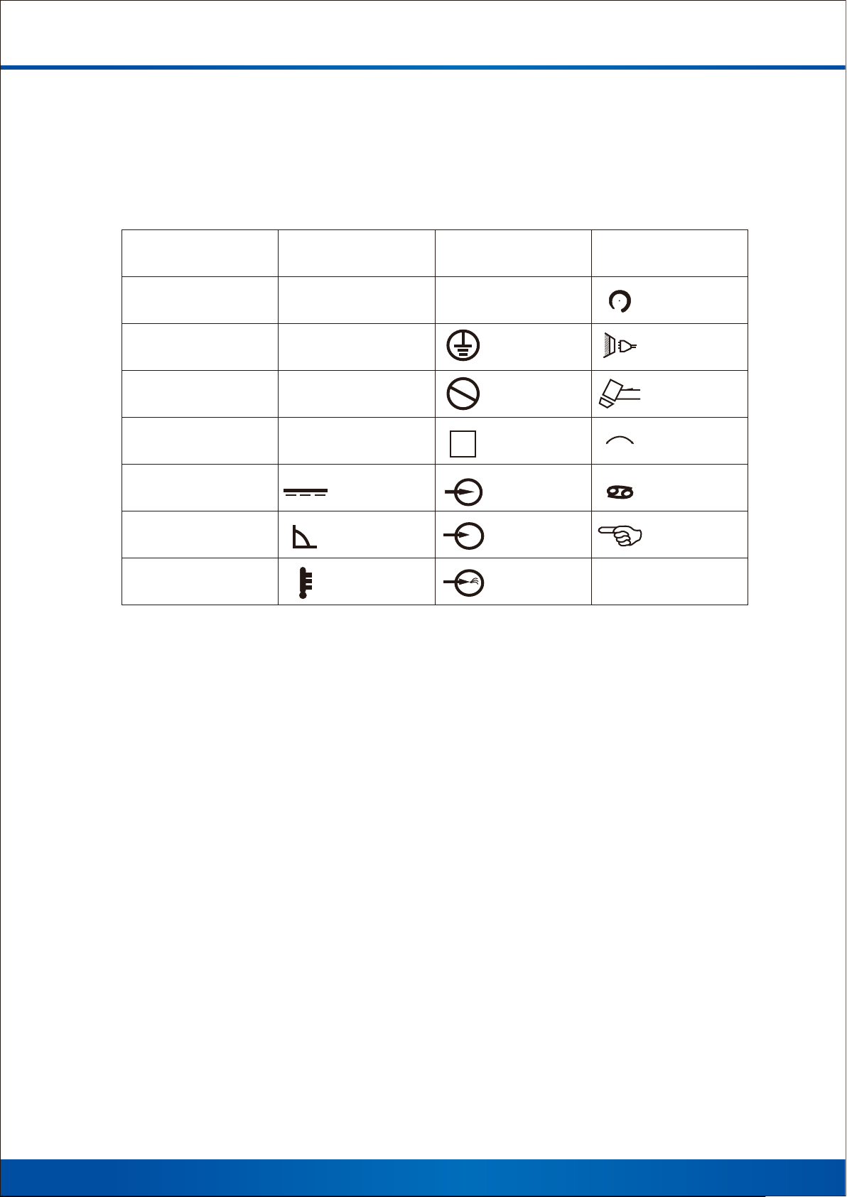
Symbols and Definitions
A
V
I
2
S
1
HZ
U
1
U
0
U
2
Amperes
Volts
Ra te d we ld in g
cu rr en t
Power rating,
productof voltage
and current(KVA)
Hertz
Pr im ar y vo lt ag e
Rated no load
voltage(Aaverage)
Conventional
load voltage
I
1m a x
I
1eff
IP
1
~
X
Rated maximum
supply current
Maximum effective
supply current
Degree of protection
Si ng le p ha se
Du ty c yc le
Direct current
Constant crrent
Temperature
I
O
S
V
On
Of f
Protective earth
(Ground)
Do not do this
Suitable for some
hazardous locations
In pu t
Vo lt ag e in pu t
Low air pressure
light
%
+ -
Pe rc en t
In cr ea se
Li ne c on ne ct io n
Lo os e sh ie ld c up
Adjust air/gas
pressure
Au to ma ti c
Ma nu al
2
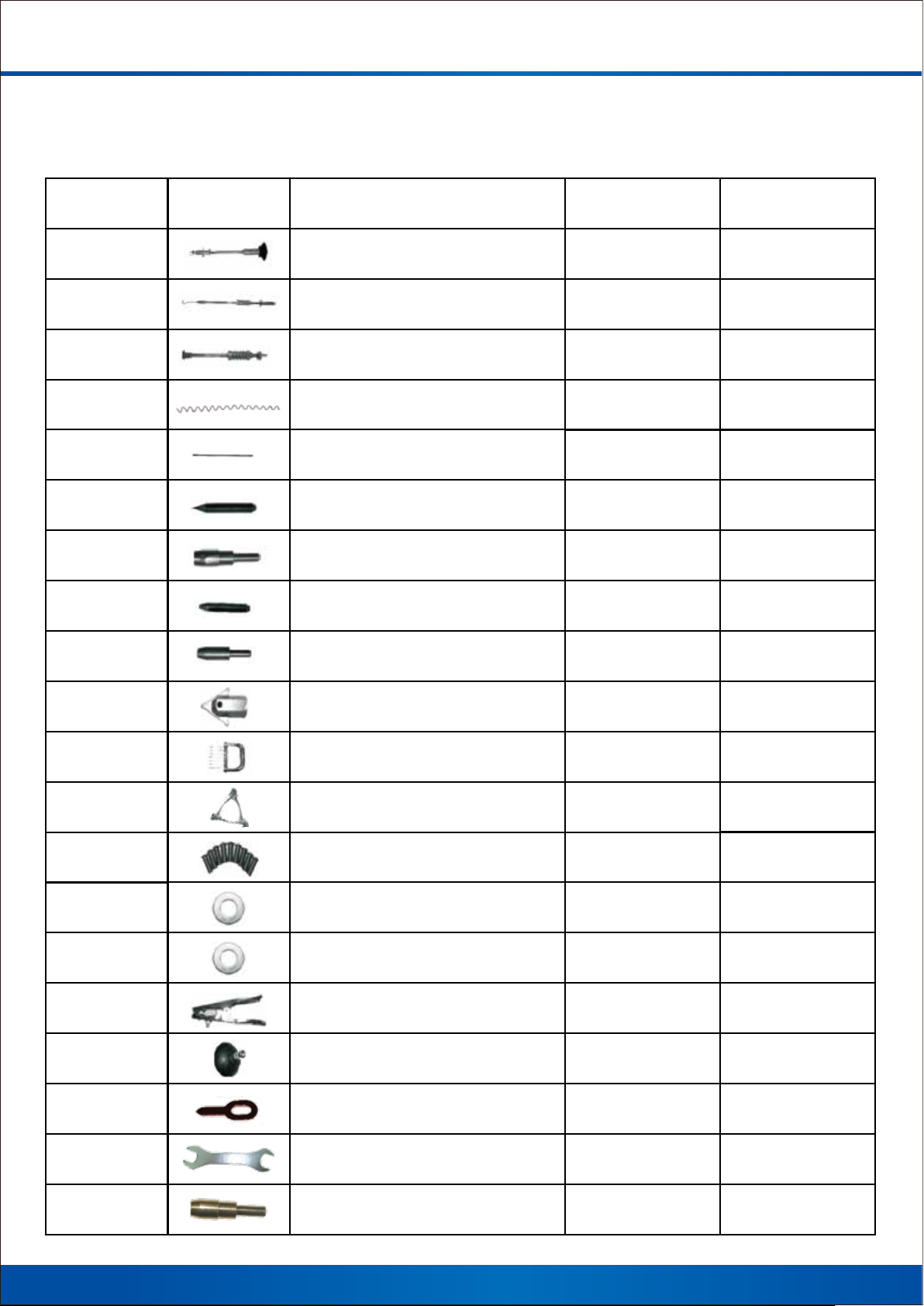
Accessories and Spare Parts List
KT NO. Product Descripon 9CCF31-1AA-B 9CCF41AA-B
KT001 Pneumac vacuum cupule
KT002 Pull hammer
KT003 Dent pulling spot hammer
KT006 Wavy wire
KT007 Carbon rod
KT008 Spot welding electrode p
KT009 Carbon and connector
KT010 Wavy wire electrode p
KT011
Washer connect
X
1 Set
1 Set
15 PCS
3 PCS 3 PCS
1 PCS
1 PCS
1 PCS
1 PCS
X
1 Set
X
X
X
1 PCS
X
1 PCS
KT013 Triangle washer connect
KT014 Claw
KT015 Triangle washer
KT016 Stud
KT017 Ø12mm washer
KT017-1 Ø10mm washer
KT018 Earth clamp
KT019 Manual cupule
KT030 OT washer
X
1 PCS
10 PCS
X
15 PCS
15 PCS
1 PCS
1 PCS
X
1 PCS
1 PCS
10 PCS
X
15 PCS
15 PCS
1 PCS
1 PCS
X
KT033 W
KT034 Stud connect
rench
or
3
1 PCS
X
1 PCS
X
Installation
1. Specifications
Model 9CCF31-1AA-B 9CCF41AA-B
Input voltage
220V / 380V
50/60Hz
Input power 6.5 KVA 6.3 KVA
Input current 42A/14A 40A/12A
Max instant current 2600A 2500A
Output power 1-13V 1-13V
Electronic
Operaon way
mer connuously
Welding me 0-99 s 0-99 s
Dimensions 370 * 230 *280 mm 370 * 230 *280 mm
Weight 9.5 kg 9.0 kg
220V / 380V
50/60Hz
Electronic
mer connuously
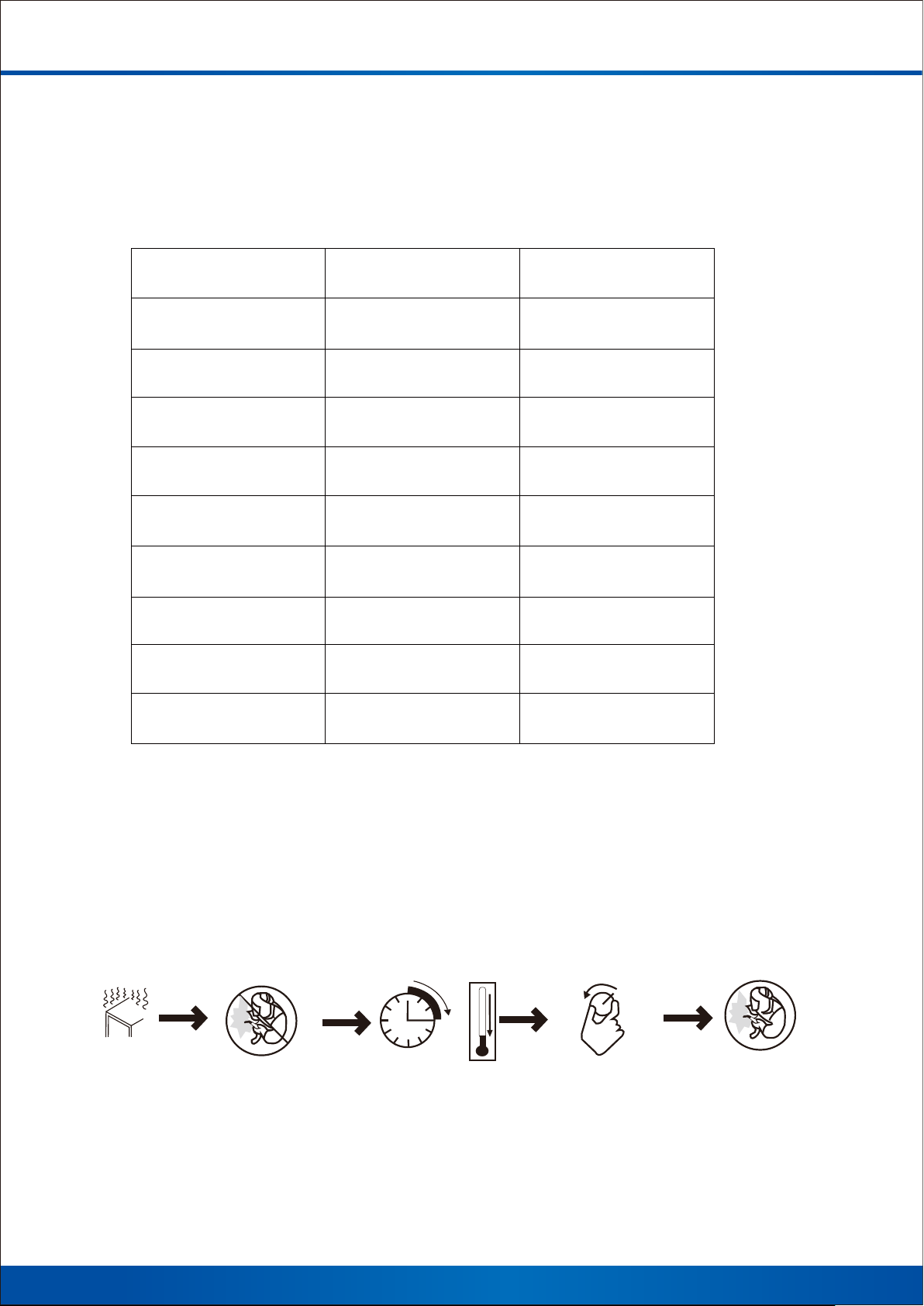
2. Duty Cycle and Overheating
Duty cycle is percentage of 10 minutes that unit can weld at rated load
without overheating.
If unit overheat, output stops, and cooling fan runs. Wait 15 minutes for
unit to cool. Reduce amperage or duty cycle before welding.
0
A
15
Overheating
Stop working Wait fifteen minutes
for unit to cool
Reduce amperage
or reduce duty cycle
Weld again
4

3. Machine Installation
Open the package and check the details of supplied accessories than
properly install this equipment as follow diagram.
4. Selecting a Location
a. Select a correct location to place the unit.
b. Determine input power cord length according to its actual operation requirement.
Input power cord must have a minimum inside diameter of 6mm² .
c. Use cart or unit handle to move unit. Do not pull the cords to move or operate unit
where it could tip.
5

5. Connecting Input Power
AC 220V
3
AC 380V
2
L1
L2
3
L3
1. Input power cord. (not less than 6mm² copper cord)
2. Over-current protection.
3. Disconnect device line terminals.
4. Ground wire L1 / L2 input conductors.
■ Installation must meet all national and Local
Codes-have only qualified persons make this installation.
■ Disconnect and lockout/tagout input power before
connecting input conductors from unit.
■ Select type and size of over-current protection.
■ Close and secure door on disconnect device.
Remove lockout / tagout device, and place switch
in the “on” position.
6

Operation
1.Controls
11
12
7
8
5 6
1
2
3
9
4
10
1. Power indicator
2. Error indicator
3. Overheat indicator
4. Gun trigger indicator
5. Spot welding time display
6. Power percentage display
7 / 8. Spot welding time adjustment
9 / 10. Power percentage adjustment
Instruction:
1. Connect input power properly and safely.
2. Turn on the power switch and selection buttons according to required
working mode.
3. Appropriately adjust welding time and power according to actual situation.
4. After setting the parameters, the machine enters into standby mode and
is ready to weld.
5. When the temperature exceeds normal working temperature, the indicator
will light and overload protection will start. Wait few minutes until the light off,
then use the machine again.
6. The error indicator will light when the machine goes wrong, and the machine
enters into automatic protection mode. Cut off the power supply then check,
use the machine again until the problems are solved.
7

2. Welding Gun and Adaptors
2
Single-Sided applications
1
1. Electrode holder
2. Trigger
Connection of negative wire
1. Weld two washers onto the dented
area that needs repairing.
2.Put the ground cable onto
the welded washers.
Carbo Rod Shrinking
OT Washer Welding
Washer Welding
Stud Welding
Single-sided Welding
Wave form Wire Welding
Pulling Spot Hammer
5. Tighten the screw to
securely fix the clamp.
3. Place the earth
clamp over the
welded washers.
8
4. Insert the bolt through
washers and clamp.

3. Operation
a. Spot Welding
Connect negative outside
wire to a clean paint free
location on metal workpiece
as close to welding area as
possible
Set correct time
.
Connect spot welding
electrode tipwith welding
gun and tighten
Select welding function Approximately a 90° angle to
Set correct power
(Position C is recommend)
the workepiece surface
Put on pressureand press trigger
Remark :
1. Setting amperage too high or time too long can cause workpiece surface damage.
2. Setting correct amperage and time according to the workpiece thickness.
3. Continuing another operation is applicable after these procedures finished.
If not, please shut the power off and switch off the unit.
9

b. Washer Welding
Connect negative outside
wire to a clean ,paint free
location on metal workpiece
as close to welding area
as possible.
Set correct time.
Connect washer adaptor with
welding gun and tighten,
Install washer.
Select welding function. Approximately a 90°angle.
Set correct power.
(Position A orB is recommend)
to the dent. Put on pressure
and press trigger.
Remove welding gunHook
the washer with pull hammer
Slide the hammer to opposited
irection to pull out the dent .
Remark :
1. Setting amperage too high or time too long can cause workpiece surface damage.
2. Setting correct amperage and time according to the workpiece thickness.
3. Continuing another operation is applicable after these procedures finished.
If not, please shut the power off and switch off the unit.
10

c. Triangle Washer Welding
Connect negative outside
wire to a clean paint free
location on metal workpiece
as close to welding area
as possible.
Set correct time.
Connect triangel washer
pull hammer with welding gun.
Select welding function.
Set correct power
(Position A is recommend)
Approximately a 90° angle to the
dent. Put on pressure and
press trigger.
Slide the hammer to opposite
directionto pull the dent.
Remark :
1. Setting amperage too high or time too long can cause workpiece surface damage.
2. Setting correct amperage and time according to the workpiece thickness.
3. Continuing another operation is applicable after these procedures finished.
If not, please shut the power off and switch off the unit.
4. Triangle washer welding can replace washer welding. It can draw out the concavity
directly after welded.
11

d. Carbon Rod Heating
Connect negative outside
wire to a clean paint free
location on metal workpiece
as close to welding area
as possible.
Set correct time.
Connect carbon rod and
carbon rod adaptor with
welding gun.
Select welding function.
Set correct power
(Position A is recommend)
Turn carbon rod clockwise to heat up
the entire convexity surface.
.
Cool the surface with a wet
rag or compressed air.
Remark :
1. Setting amperage too high or time too long can cause workpiece surface damage.
.
2. Setting correct amperage and time according to the workpiece thickness.
3. Continuing another operation is applicable after these procedures finished.
If not, please shut the power off and switch off the unit.
12

e. Wriggle Form Wire Welding
Connect negative outside
wire to a clean paint free
location on metal workpiece
as close to welding area
as possible.
Set correct time.
Connect wave form wire electrode
tip with welding gun.
Select welding function.
Set correct power
(Position A is recommend)
Place a wave form wire horizontally
on the dent Approximatelya 90°angle
to wave form wire Put on pressure
and press trigger.
Connect hook puller with pull hammer
Hook wave form wire and slide
the hammer to pull out the dent.
Remark :
1. Setting amperage too high or time too long can cause workpiece surface damage.
2. Setting correct amperage and time according to the workpiece thickness.
3. Continuing another operation is applicable after these procedures finished.
If not, please shut the power off and switch off the unit.
13

f. Cupules
Manual operating cupule
1. Connect manual operating cupule with pull hammer.
2. Push manual operating cupule in to lock the cupule on the concavity.
3. Slide the hammer to opposite direction to pull the dent out.
Pneumatic vacuum cupule
1. Connect gas/air supply with the adaptor of cupule.
2. Open the valve, sticking cupule to the dent.
3. Slide the hammer to opposite direction to draw the concavity out.
4. Cupule falls off when close the valve.
14

Maintenance
1. Troubleshooting
Problems
No weld output
Trigger not working
Poor weld
Piercing workpiece
Causes Solutions
1. Connected powersupply incorrectly
2. Power switch in off position
1. Trigger damaged
2. Gun control wire broken
3. Control wire plug loosen
4. Mode switch in incorrect position
1. Aamperage too low
2. Weld time too short
3. Input power cord did not meet the
requirement
4. Ground clamp bad contact
1. Output amperage too high
2. Weld time too long
3. Badcontact of electrode tip or
washer with workpiece
1. Connect power supplyaccording to
manufacturer’structions
2. Place power switch in “on”
1. Replace trigger
2. Connect again or replaceif
nec-essary
3. Connect control wire plug again
4. Place Mode switch in correct
pos-ition
1. Increase amperage setting
2. Increase time setting
3. Replace input power cord
4. Change ground clamp location
1. Reduce amperage setting
2. Rrduce weld time
3. Remove coating from material
reduce added pressure
Kriptol working
unstable
Unit stop working
while operation
1. Kriptol did not polish,workpieces
did not polish
2. ncorrect amperage and time setting
1. Trigger plug loosen
2. Gun control wire broken
3. Over heating
1. Polish kriptol and workpieces
2. Set amperage and time according
to workpiece thickness
1.Checkguncontrol wire and
trigger plug
2.Wait for temperature cool down
15

www.kingtony.com
customer service e-mail : service@kingtony.com
899DS11-KT 297x210mm
1
 Loading...