

KingTing Tech KT1276 User Manual

Long Range LoRa™ TechnologyTransceiver Module
LoRa Technology Transceiver Module
KT1276 provides an easy to use, low
trademark of Semtech Corporation.
ASCII command interface over UART
38.8• Castellated SMT pads for easy and reliable PCBmounting
Environmentally friendly, RoHS compliant
:Modular Certified for the United States (FCC)
Device Firmware Upgrade (DFU) over UART
V to 3.6V (3.3Vtypical)
40°C to +85°C
64 Node Identity
Power Long Range Transceiver operating in the 91
High Receiver Sensitivity: down to
FSK, GFSK, and LoRa Technology modulation
• Wireless Alarm and Security Systems
Industrial Monitoring and Control
transceiver module features LoRaTechnology RF modulation, which provides long
cation with high interferenceimmunity.
Figure
KT1276
, which developed by KingTing Tech
power solution for long range wireless data
3 show the module’s top view, the pinout, andthe block
KT1276 is a
Corporation.
transmission.
LoRa™ is a registered
General Features
-
•
• Compact form factor: 20.3 x
•
• Compliance
•
Operational
• Single operating voltage: 2.1
• Temperature range: -
• Low-power consumption
• LoRa™ Technology modulation
• Integrated MCU, Crystal, EUI-
• 3PINs for control and status
• Low-
•
•
Applications
x 3.2 mm
8 MHz frequency band
-138.8dBm
• Automated Meter Reading
• Home and Building Automation
•
• Internet of Things (IoT)
1.0Device Overview
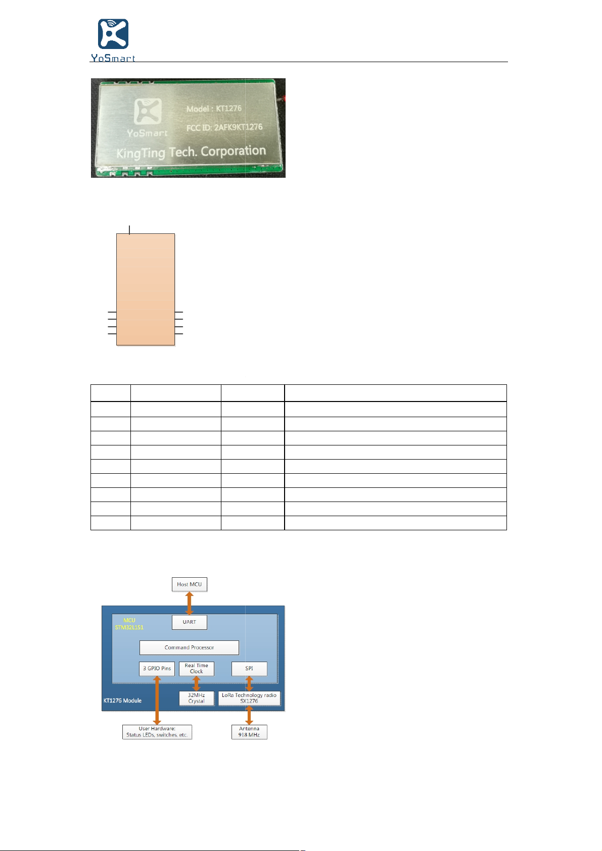
The KT1276
rangespread spectrum communi
Figure 1-1, Figure 1-2, and
diagram.
FIGURE 1-1: KT1276 TOP VIEW
1-
2017 KingTing Tech. Corporation
Long Range LoRa™ TechnologyTransceiver Module
describes the module’s pins.
Power
Input/Output
Input/Output
Input/Output
RF
analog
NRST
Output
Power
KT1276
FIGURE
1-
RF
6
NRST
TX
7
RX
8
VCC
9
Table 1-1:
Pin
1
2
3
4
5
6
7
8
9
FIGURE
1-
2: KT1276 PIN DIAGRAM
5
PA1
4
PA4
3
PA2
2
1
GND
Name
GND
PA2
PA4
PA1
RF
Input
UART_TX
UART_RX
VCC
Input
3: KT1276 BLOCK DIAGRAM
Type
Ground supply terminal
General purpose I/O pin
General purpose I/O pin
General purpose I/O pin
RF signal pin
Active-low device Reset input
Communication UART Transmit (TX)
Communication UART Receive (RX)
Positive supply terminal
Description
2017 KingTing Tech. Corporation
Long Range LoRa™ TechnologyTransceiver Module
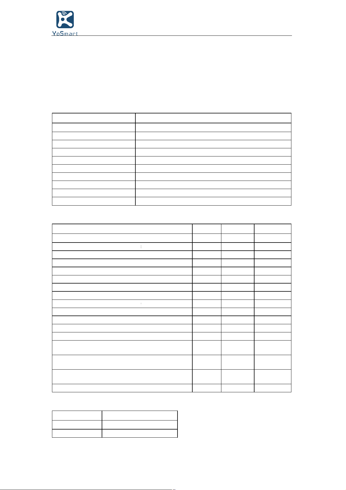
GENERAL SPECIFICATIONS
provides the general specifications for the module. Table
module's electricalcharacteristics and current consumption. Table
module's dimensions and the RF outputpower calibration data.
902.000
LoRa™
12500
Board
UART
>5
1
40°C
40°C
10%
(except
VDD)
mode
Power
on
3: CURRENT CONSUMPTION
at
9.8
21.4
KT1276
provide the
show the
Units
V
V
—
mA
—
mA
mA
mA
— V
—
V
—
V/ms
V —
V
— V — 50
nA
nA
nA
dBm
2.0
Table 2-1
Table2-1: General Specifications
Specification
Frequency Band
Modulation Method
Maximum Over-the-Air Data Rate
RF connection
Interface
Operation Range
Sensitivity at 0.1% BER
Temperature (operating) Temperature (storage) Humidity
Table 2-2: Electrical characteristics
Supply Voltage
Voltage on any pin with respect to VSS
Voltage on VDD with respect to VSS
Input Clamp Current (IIK) (VI < 0 or VI >
Output Camp Current (IOK) (VO < 0 or VO
GPIO sink/source current each
Total GPIO sink/source current
RAM Data Retention Voltage (in Sleep
VDD Start Voltage to ensure internal
VDD Rise Rate to ensure internal PowerBrown-out Reset Voltage
Logic Input Low Voltage
Logic Input High Voltage
Input Leakage at <25°C
(VSS<VPIN<VDD, Pin at high-impedance)
Input Leakage at +60°C
(VSS<VPIN<VDD, Pin at high-impedance)
Input Leakage at +85°C
(VSS<VPIN<VDD, Pin at high-impedance)
RF Input Level
TABLE 2-
Mode
Idle
RX
Parameter
Typical Current
MHz to 928.000 MHz
Technology modulation
bps with LoRa Technology modulation
edge connection
km coverage at urban area
-
38.8dBm
to +85°C
to +115°C
~ 90%non-condensing
VDD)
> VDD)
or Reset state)
-on Reset signal
Reset signal
0.8 x VDD
3V
(mA)
2-2 and Table 2-3
2-4 and Table 2-5
Description
Min.
2.1 3.6 V
-0.3
-0.3
—
—
1.5
0.05
1.75
—
—
—
Max.
VDD + 0.3
3.9
+/-20
+/-20
25/25
200/185
0.7
2.05
0.15 x VDD
100
200
+10
2017 KingTing Tech. Corporation
 Loading...