

Page 1
Pool Care System for
Above Ground Pools
Instruction Manual
Customer Service 800-222-0169
Page 2

TABLE OF CONTENTS
Introduction 3
Swimming Pool Tips 4
Start-up and Operation 5
Replacing Chlorine Pac 6-7
Winterizing 8
Cycler Maintenance 9
Parts List 10
Filter Installation 11
Base Installation 12
Warranty 13
Page 3
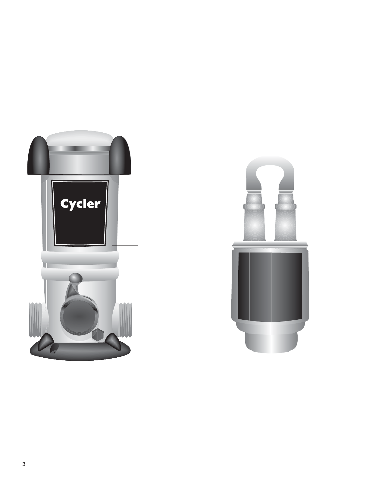
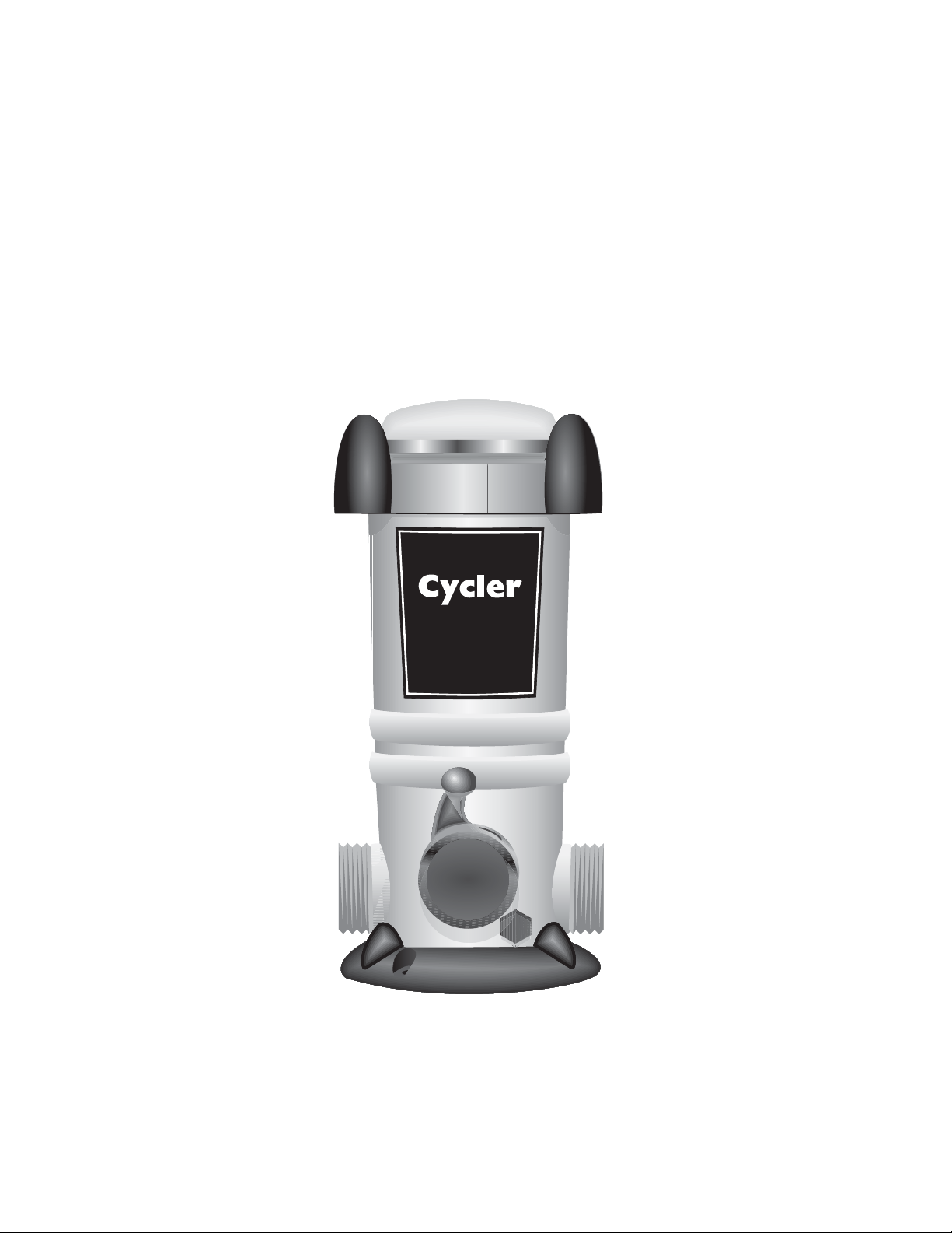
INTRODUCTION
Welcome to easier pool care that ensures crystal clear, sparkling water in your pool. This manual
will explain how to install and operate the cycler for a more enjoyable experience with less work
and worry and more time relaxing and having fun.
See label for your
Model Number
Cycler
Automatically dispenses chlorine with precise
metering for continuous sanitation.
C
h
l
P
o
A
r
C
e
i
n
Chlorine Pac
The replacement Pac is prefilled with chlorine
and fits inside the Cycler. No touching chlorine
or breathing its fumes. One Pac lasts 2 to 4
weeks.
(Pac sold separately )
Page 4
Swimming Pool Tips
Start-up and Yearly Maintenance
1.
• Make sure the pool has
adequate circulation. The
pool water must completely
circulate through the pump
and filter at least 1 to 2
times per day. This
ususally requires 8 to 12
hours. Check with your
dealer for the proper
circulation time for your
pool.
2.
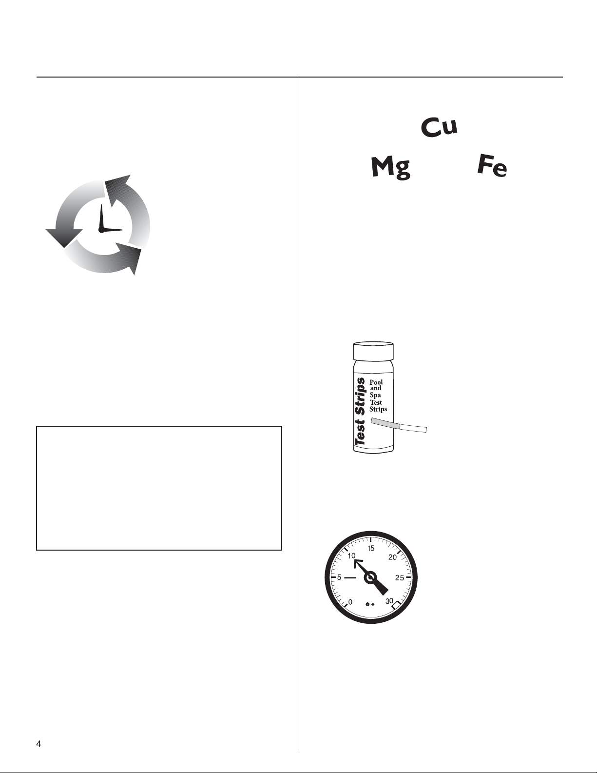
• Before beginning with any pool care program, you must
first balance your pool water. Take a water sample to your
local pool professional or use a complete test kit that will
test for the following important elements
Water Balance Guidelines
3.
• If your fill water is high in metals, use a sequestering
agent or metal out at start-up only before inserting a Pac.
See your local dealer for details on using these products
and always follow manufacturer’s directions carefully.
• Afer your pool is up and
4.
running smoothly, continue to
test your water for pH, total
alkalinity and chlorine and
maintain its balance by adding
any necessary adjustment
products (see your dealer for
details).
pH: 7.2 – 7.8
Total Alkalinity: 60 – 120 ppm
Calcium Hardness: 150 – 400
Total Dissolved Solids: <1500
Stabilizer: 20 – 80 ppm
Free Chlorine: 1.0 – 3.0 ppm
5.
• Check the pool's filter gauge
often and periodically clean
filter per the manufacturer's
directions. A dirty filter will slow
the flow of water which could
hamper proper circulation.
Page 5

Start-up and Operation
• Add a stabilizer or conditioner to
1.
the pool at the beginning of the
season if the stabilizer level is below
20 ppm. This will prevent chlorine
burn off. Follow manufacturer’s
directions carefully.
4
SETTING CONTROL DIAL
• Set control dial by matching up the parameters
4.
your individual pool needs. See #5 for below for adjusting
directions. IMPORTANT: Pump run times less than 8
hours could result in under chlorination due to inadequate
flow through the System.
of your pool on the chart below. THIS IS A STARTING
POINT ONLY and may need to be adjusted to fit
2.
• Shock the pool with chlorine to rid
the water of all contaminants before
beginning
. Follow manufacturer's
directions carefully.
• This step is very important to
start-up. Use chlorine shock only.
• Do not add shock in or near the skimmer or into the Cycler
as it could damage equipment, risk potential explosion or
discolor your pool surface.
POOL SIZE
Gallons Diameter
7,000 (18')
9,000 (21')
12,000 (24')
15,000
20,000
Dial settings based on 1.5 ppm. * Bypass installation recommended.
RECOMMENDED FLOW RATE 20-60 gpm
12 Hour Pump Run Time 24 Hour Pump Run Time
1/2 hp 3/4 hp 1 hp 1 1/2 hp 1/2 hp 3/4 hp 1 hp 1 1/2 hp
2.5 2 1 3 1.5 1 1 2
3 2.5 2 3.5 2 1.5 1 2.5
3.5 3 2.5 2 2.5 2 1.5 3
4 3.5 3 2.5 3 2.5 2 1.5
4.5 4 3.5 3 3.5 3 2.5 2
PUMP SIZE PUMP SIZE
*
*
• For the first week test the
5.
l
P
o
o
a
n
d
S
a
p
t
T
s
e
s
p
S
i
t
r
pool water daily for free
chlorine to ensure correct dial
setting. Continue to test
weekly throughout the season.
Test Strips
Test strips recommended.
• After each testing, adjust the
4
dial up by 1/2 increment if the
free chlorine reading has dropped
below 1.0 ppm or adjust down
by 1/2 increment if the reading
has risen above 3.0 ppm.
Continue this process each day until the reading stabilizes
between 1.0 and 3.0 ppm.
*
*
*
3.
• When chlorine reading is
down to 1.0 ppm, which may
take a few days, insert pac
into cycler.
(Follow directions
on Page 6.)
Remember to adjust dial by 1/2 increments only in order
to prevent over chlorination which may bleach pool
surfaces.
• Shock pool every two weeks or as
6.
needed to maintain water quality. Follow
label directions on the shock treatment
used.
• Do not add shock in or near the skimmer
or into the Cycler as it could damage
equipment, risk potential explosion or
discolor your pool surface.
Page 6

Replacing a
Chlorine Pac
1.
2.
Back of
Cycler
CAUTION Read Carefully – USE ONLY the factory recommended replacement Pac. (See
label.) DO NOT USE any other Pac or bulk chemical tablets in the Cycler. Use of any
other product could result in over chlorination, bleached liners, unsafe pool conditions,
fire or explosion. Warranty will be void if the correct Pac is not used.
• Turn off pump. Turn dial to
0. This reduces the flow of
water into the unit when the
cap is open so isolation
valves are unnecessary.
• Unscrew knob to relieve
pressure.
B. If using a cutting tool,
place curved section of tool
around the narrow end of
one Pac tower and line up
blade on indent.
C. Squeeze the handles
together. Repeat for other
side.
3.
4.
Cutting handle from Pac using a cutting tool
5.
or hacksaw (KEEP OUT OF REACH OF CHILDREN)
Indent in plastic
• Remove Cycler cap. Stand
back upon removing cap to
avoid inhaling fumes.
• The Pac is made of HDPE
plastic. When the Pac is empty,
triple rinse in pool water, drain,
and recycle or wrap in
newspaper and discard in trash.
D. If using a hacksaw to
cut the Pac, line up hacksaw blade on indent and
cut with a smooth sawing
action.
Finished cut ends
E. Whether using a cutting
tool or a hacksaw make
sure the blade comes
straight across on the
indent line for a clean cut.
Avoid a
pinched
A. Find the indent in the
plastic.
6
opening.
A correct
oval
opening
F. If openings are pinched
together, open with fingers
or re-cut closer to the
colored screens inside Pac.
Leave at least 1/4" of plastic
to fit into Cycler base.
Page 7

6.
Pac
towers
Pac
towers
• Turn Pac over and shake
slightly until tablets fall into
tower areas.
9.
• Replace cap by hand only.
DO NOT OVER TIGHTEN.
7.
8.
Opening
in Pac
Key in
Cycler
• Insert Pac into Cycler, lining
up the openings in Pac with
keys in Cycler.
NOTE: Openings are a
different shape than keys.
• Insert Pac into Cycler. Avoid
sparks, open flame or smoking when handling the Pac.
10.
• Replace knob on the
Cycler.
Back of
Cycler
7
Page 8

Winterizing
1.
2.
Back of
Cycler
• Turn pump off and turn
dial to Setting 0.
• Unscrew knob to relieve
pressure.
4.
• Unscrew knob from the
front of Cycler. Allow all
water to drain.
5.
• If Pac still contains
chlorine wrap in plastic bag
and store in shed or cool
well-ventilated location
away from children, pets,
motorcycles, cars or
anything metal that can
rust, pit, etc. Make sure
Pac is away from open
flame.
3.
8
6.
• Remove cap.
• Replace the cap and
knobs loosely.
Page 9

Cycler Maintenance
Replacing the Control Dial O-Rings
1.
Center of locking pin
• In the back of the Cycler
depress center of locking
pin with a finger and pull
pin out of dial.
2.
• Turn control dial back
and forth as you pull it out
of the housing.
3.
O
S
I
L
U
B
• Replace both o-rings.
T
Y?
H
P
E
R
O
C
E
L
I
N
C
O
T
N
R
A
I
C
Apply silicone lubricant
that came with your Cycler
C
Y
O
P
C
OPY
C
O
P
Y
on o-rings.
C
O
Y
P
Replacing Cap O-Ring
O
?
T
Y
H
P
E
R
O
C
S
I
E
L
I
N
C
O
L
U
T
B
N
R
A
I
C
C
O
Y
P
C
OPY
C
O
Y
P
C
Y
O
P
1. Hold cap in front of you
upside down with the o-ring
groove facing up. Place one
end of o-ring into cap groove
at the point closest to you.
Hold o-ring down with the
thumb and index finger of one
hand.
2. Take hold of the far end of
the o-ring with the thumb and
index finger of the other hand.
Roll o-ring slightly back
towards you as you stretch the
o-ring into the remainder of the
cap groove.
3. Lubricate o-ring often with
silicone lubricant that came
with your Cycler. DO NOT
USE petroleum based
lubricants.
4.
5.
9
• Carefully insert control
dial back into housing.
• Replace locking pin by
pushing it through the
slots on the dial until it
locks into place.
Replacing a Knob
• To replace, simply unscrew
and replace with the new one.
• Front of Cycler
• Back of Cycler
Page 10

Parts List
1
2
8 & 9
3
11
O
?
T
Y
H
P
E
R
O
C
S
I
E
L
N
I
C
O
L
T
U
N
B
R
A
I
C
C
Y
O
P
C
Y
O
P
C
O
Y
P
C
Y
O
P
Included with Above Ground Model 170 and 6700
REF. # DESCRIPTION QTY. INC.
12
5
4
7
6
9
8
1 & 2 Cap w/O-Ring 1
3 Body 1
4 Pressure Relief Valve 1
5, 6, 7 Control Dial with O-Rings & Locking Pin 1
8 & 9 Knob with O-Ring 2
11 Nipple Kit 1
12 Silicone Lubricant 1
Replacement Parts for Above Ground Model 170 and 6700
REF. # ORDER # DESCRIPTION
1 & 2 01-22-1418 Cap w/O-Ring
2 01-22-1920 Cap O-Ring
4 01-22-9480 Pressure Relief Valve
5, 6, 7 01-22-1443 Control Dial with O-Rings & Locking Pin
6 01-22-1450 Control Dial O-Ring Set
8 & 9 01-22-9940 Knob with O-Ring
10 01-22-1480 Mounting Base
11 01-22-1710 Nipple Kit
12 01-22-9971 Silicone Lubricant
10
Optional part - not included
10
Page 11

TOOLS NEEDED:
Screwdriver
Pipe Wrench
INCLUDED
WITH CYCLER:
One Hose Adapter
1 1/2" X 1 1/2" X 1 1/4"
Pipe Thread Tape
or Sealant
MATERIALS NEEDED:
One 6" X 1 1/2" TBE
PVC Nipple
Above Ground Filter Installation
2.
Screw one end of nipple
1.
Apply pipe thread tape or
sealant to each threaded end
of nipple.
Apply pipe thread
4.
tape or sealant to
threaded end of hose
adapter.
into the filter return.
Tighten turning 1 to 2
revolutions with wrench.
DO NOT OVER TIGHTEN.
Screw adapter into the
5.
other side of Cycler.Hand
tighten. Finish tightening by
turning 1 to 2 revolutions
with wrench.
DO NOT OVER TIGHTEN.
Screw either side of
3.
Cycler on to open nipple
end until upright and
secure.
Bi-flow valve
design allows
water flow in
either
direction.
One Section of
1 1/2" Flex Hose
(provided with filter)
One
Hose
Clamp
RECOMMENDED:
Corrosion Resistant
Check Valve
11
HOSE ADAPTER
HOSE
ADAPTER
HOSE
ADAPTER
6.
Attach return section of hose
to the adapter with clamp.
Tighten clamp with
screwdriver.
7.
When using a Chlorine Pac,
installing a corrosion resistant
check valve is
recommended.
Page 12

TOOLS NEEDED:
Above Ground, Base Installation
Screwdriver
Pipe Wrench
INCLUDED
WITH CYCLER:
Two Hose Adapters
1 1/2" X 1 1/2" X 1 1/4"
Pipe Thread Tape
or Sealant
MATERIALS NEEDED:
Two Sections of
of 1 1/2" Flex Hose
(one provided with
filter)
PUMP
FILTER
TO POOL
The Cycler should always be installed between the
filter and pool (or between heater and pool if applicable).
Apply pipe thread tape or
1.
sealant to the threaded end
of both hose adapters.
Screw adapters into each end of Cycler. Hand tighten.
2.
Finish tightening by turning 1 to 2 revolutions with
wrench. DO NOT OVER TIGHTEN.
Two
Hose
Clamps
RECOMMENDED:
Corrosion Resistant
Check Valve
#10 X 1 1/4" Phillips Pan
Head Screws with
Washers
OPTION:
Half Union
or
1 1/2" Threaded by
1 1/2" Slip Bushing.
When installing with
hard PVC pipe, use
either a half union on
the outside port threads
or a bushing on the
inside port threads.
Attach the filter section of
3.
flex hose to one hose
adapter and the return
section of flex hose to the
other hose adapter with
clamps and tighten with
screwdriver.
HOSE
1 1/2" X 1 1/2" X 1 1/4"
CLAMP
HOSE ADAPTER
FILTER &
PUMP
HOSE
CLAMP
4.
HOSE
ADAPTER
CHECK
VALV E
BUSHING
TOE NIPPLE
HOSE
ADAPTER
HOSE
CLAMP
TO POOL
Installing a corrosion resistant check valve is recommended.
5.
For better stability, Cycler may
be mounted on a base using
Phillips pan head screws.
One in front and two in back.
12
Page 13

Limited One-Year Warranty
King Technology, Inc. warrants to the original purchaser this
unit will be free from any defects in workmanship and/or
material, for a period of one (1) year from the date of original
purchase. This warranty covers body, cap and control dial, but
specifically excludes o-rings. King Technology at its option may
replace any defective parts or the entire unit without charge
after it is determined what is needed to correct any deficiency.
Replacement parts with the exception of o-rings are warranted
for the remainder of the original warranty.
1. To obtain warranty service, you must deliver the unit to King
Technology or its nearest authorized dealer. Shipping expenses
are the purchaser's responsibility. The name of the nearest
authorized dealer can be obtained by writing or calling King
Technology at the address and telephone number provided
on back page. Proof of purchase is required when requesting
warranty service. Purchaser must present the sales receipt or
other documentation verifying proof of purchase.
2. This warranty does not cover defects caused by: Modification,
alteration, repair or service of the unit contrary to the
accompanying instructions; physical abuse to or misuse of the
product or operation or installation in a manner contrary to the
accompanying instructions. This warranty also excludes all
costs arising from the installation, adjustment, removal or
replacement of defective units or parts. This warranty also
excludes any and all claims arising out of the chemicals used
in the product or their characteristics.
3. CAUTION - Read carefully – Failure to follow these
instructions will void the warranty. Do not add shock in or
near skimmer.
A. This unit is not designed for shock treatment of pools.
See your pool dealer or distributor for further information
concerning shock treatments.
C. Excess trichlor in the pool can create health hazards to bathers.
Consult each chemical manufacturer's warnings and cautions for
specifics.
D.
Misuse or failure to use the proper chlorine Pac for product
as directed in the instruction manual may cause damage to
equipment or personal injury. This warranty will be null and void
if this unit is not used with the recommended chlorine Pac or
Trichlor tablets.
4. This warranty is the exclusive warranty for the 170 and 6710 Cycler.
This warranty is not transferable. KING TECHNOLOGY MAKES NO
REPRESENTATION OR WARRANTY OF ANY KIND, EXPRESS OR
IMPLIED, AS TO MERCHANTABILITY, FITNESS FOR A PARTICULAR
PURPOSE OR ANY OTHER MATTER CONCERNING THE 170 and
6710 CYCLER. Any express warranty not provided herein, and any
remedy for breach of contract but which for this provision might arise
by implication or operation of law is hereby excluded and disclaimed.
THE EXCLUSIVE REMEDY FOR ANY CUSTOMER IS THE REPAIR
OR REPLACEMENT OF THE UNIT, AND THE RECOVERY OF
DAMAGES WILL NOT EXCEED THE PURCHASE PRICE OF THE
UNIT. IN NO EVENT WILL KING TECHNOLOGY BE LIABLE FOR ANY
INCIDENTAL, CONSEQUENTIAL, SPECIAL OR PUNITIVE DAMAGES
FROM ANY CAUSE.
5. Under no circumstance shall King Technology be liable to purchaser
or any other person for any damage or loss incurred because of any
chemicals used in the product or their physical characteristics, or
interruption of service of the product, or any resulting special, incidental
or consequential damages or losses. Some states do not allow the
exclusion or limitation of incidental consequential damages, so the
above limitation or exclusion may not apply to you.
B. Control dial settings in excess of the recommended
setting levels for trichlor can result in excess sanitizers
being discharged into the pool. This can result in bleaching
or discoloration of areas around the pool inlet or in some
cases bleaching or discoloration of the entire pool liner
or paint.
DO NOT FORGET – Fill out warranty card and return postage paid.
Manufactured by: KING TECHNOLOGY, INC.
530 11th Avenue South, Hopkins, MN 55343 U.S.A.
952-933-6118 • 800-222-0169 • FAX 952-933-2206
www.kingtechnology.com
Made in U.S.A.
U. S. Patent Numbers: 4,662,387; 5,076,315; 5,218,983;
6,210,566; D540,906 and other U.S. and Foreign Patents Pending.
20-48-0129E 553100743R3N
13
 Loading...