

Page 1
TM
PERFORM-MAX
POOL SANITIZER
Models 920, 940 & 980 (In-line)
Model 960 (Off-line)
DESINFECTANTE PARA PISCINAS
TM
PERFORM-MAX
Modelos 920, 940 y 980 (dependientes)
Modelo 960 (autónomos)
H
L
C
O
I
R
R
T
S
L
O
O
P
R
E
L
L
A
M
S
S
A
P
S
R
E
G
R
A
L
P
O
O
L
S
Model 940 • Modelo 940 Model 920 • Modelo 920
Instruction Manual • MANUAL DE INSTRUCCIONES
Page 2

English
Español
TABLE OF CONTENTS
Page No.
Introducing Perform-Max 3
Pool Balancing 3
Installation Introduction 4
Parts List Model 920 5
Parts List Model 940, 960, 980 6
Above Ground Base Installation 7
Above Ground Filter Installation 9
In Ground In-line Installation 11
Off-line Installations 13-14
For Proper Performance 17
Refilling Chemicals 18
Changing Chemicals 18-19
Setting Control Dial 19
Replacing Control Dial O-rings 22
Replacing Cap O-ring & Knob 23
ÍNDICE DE CONTENIDOS
Núm. de
página
Presentación de Perform-Max 3
Cómo equilibrar la piscina 3
Introducción para la instalación 4
Lista de partes Modele 920 5
Lista de partes Modelos 940, 960, 980 6
Instalación básica sobre el suelo 8
Instalación del filtro sobre el suelo 10
Instalación dependiente en el suelo
(excavada) 12
Instalación autónoma 15-16
Para un rendimiento adecuado 17
Cómo rellenar los productos químicos 20
Cómo cambiar los productos químicos 20-21
Cómo programar el comando de control 21
Cómo cambiar los anillos de cierre del
comando de control 22
Winterizing 23
Warranty Back
For information on all King Technology
products, visit our website at
www.kingtechnology.com
Cómo cambiar el anillo de cierre de la tapa
o la perilla 23
Cómo acondicionar para el invierno 23
Garantía
atrás
Para obtener información acerca de todos los
productos de King Technology, visite nuestro
sitio web en www.kingtechnology.com
2
Page 3
Thank you for choosing the
Perform-Max Pool Sanitizer
for your pool.
Perform-Max precisely
meters chlorine at a
consistent rate so you are
ensured of a properly
sanitized pool with less
work and more time
to enjoy.
Gracias por elegir el
desinfectante Perform-Max
para su piscina. Perform-Max
mide el cloro de forma
precisa y constante por lo
que usted está seguro de
tener una piscina
desinfectada
adecuadamente con menos
trabajo y con más tiempo
para disfrutar.
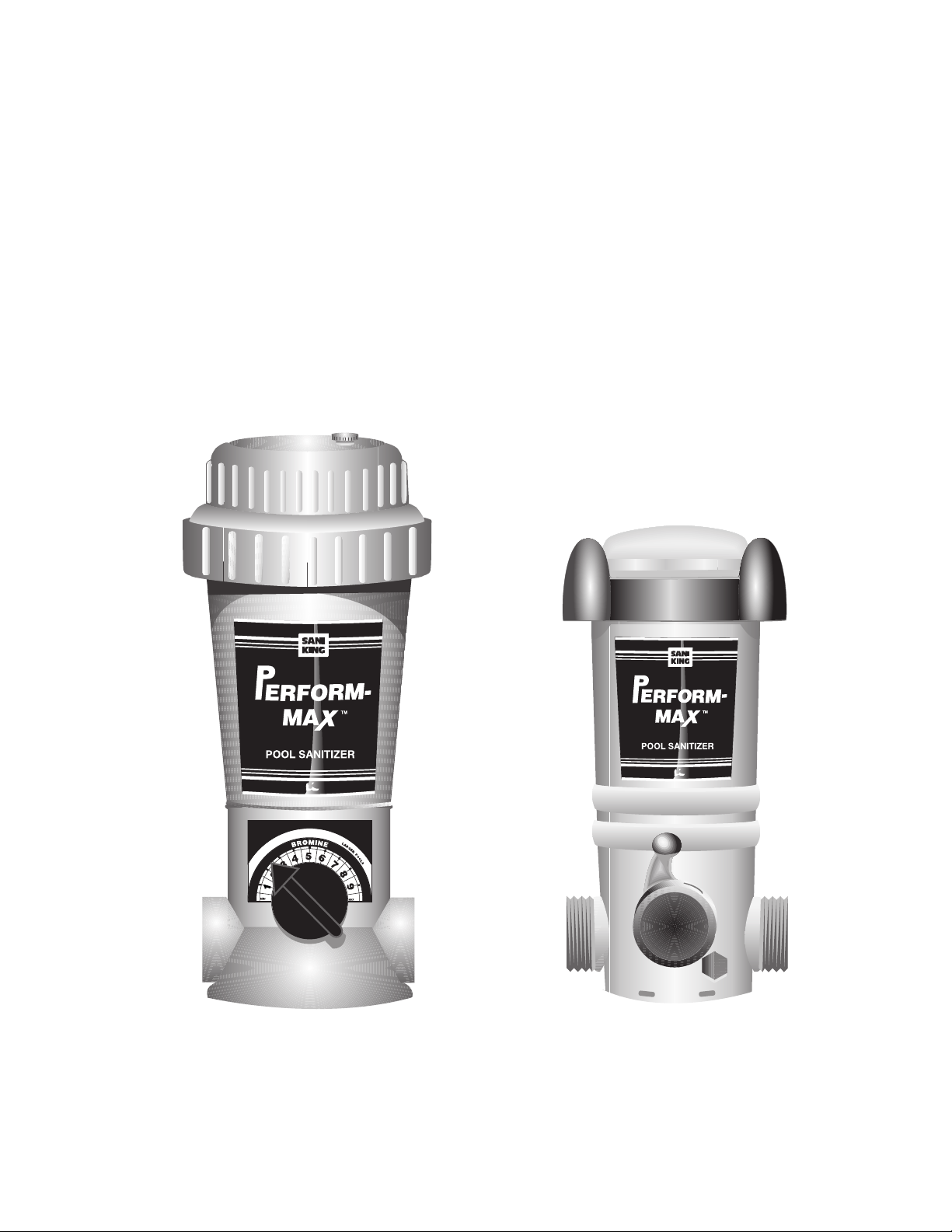
• In-line unit for in
ground pools
(Models 940 and
980)
• La unidad de la enlínea para en molió
las piscinas
(Modelos 940 y 980)
• Off-line unit for in
ground and above
ground pools
(Model 960)
• La unidad
desconectada para en
el suelo y encima de
molió las piscinas
(Modelo 960)
• In-line unit for
above ground pools
(Model 920)
• La unidad de la enlínea para encima de
molió las piscinas
(Modelo 920)
Benefits
• Sanitizes with
M
A
H
C
L
O
I
R
R
T
M
S
I
O
N
L
L
R
E
A
O
B
R
O
G
P
E
R
R
E
P
L
O
L
5
6
O
A
L
4
M
S
S
S
7
A
P
P
3
S
O
8
O
R
L
E
S
G
2
R
A
9
L
1
M
I
N
X
A
M
M
A
H
L
C
O
I
R
R
T
M
I
N
O
S
L
R
E
L
A
B
O
R
O
G
P
E
R
R
E
P
L
O
L
6
5
O
A
4
M
S
S
7
A
P
P
3
S
O
O
8
R
L
E
G
2
R
A
9
L
1
M
I
N
X
A
M
Chlorine or Bromine.
• Large capacity with a wide
mouth for easier refilling.
• Bi-flow design means unit
can be installed in either
direction.
• Wide range of control dial
settings to meet the precise
needs of each pool.
• Erosion design offers
better efficiency so
chemicals last longer.
L
S
S
• Pressure relief valve offers
safety feature against
built-up pressure.
Beneficios
• Desinfecta con cloro o bromo.
• De gran capacidad y boca ancha
para un fácil rellenado.
• El diseño bi-flujo significa que
la unidad puede ser instalada
en cualquier dirección.
• Amplio rango de
programaciones del comando
de control para satisfacer las
necesidades precisas de cada
piscina.
• El diseño anti-erosión ofrece
una mayor eficacia para que los
productos químicos duren más
tiempo.
• La válvula de alivio de presión
presenta una función de
seguridad para evitar la alta
presión.
Pool Balancing
1. Before using your PerformMax Sanitizer, you must first
balance your pool water. Take
a water sample to your local
pool professional or use a
complete test kit that will test
for the following important
elements.
Water Balance Guidelines
Free Chlorine: 1.0 – 3.0 ppm
Free Bromine: 2.0 – 5.0 ppm
pH: 7.2 – 7.8
Total Alkalinity: 60 – 120 ppm
Calcium Hardness: 150 – 400
Total Dissolved Solids: <1500
Stabilizer: 20 – 80 ppm
2. If your fill water is high in
metals, use a sequestering
agent or metal-out at pool
opening. Follow
manufacturer’s directions.
3. After your pool is up and
running smoothly, continue to
test your water for pH, total
alkalinity and chlorine and
maintain its balance by adding
any necessary adjustment
products (see your dealer for
details).
4. To achieve an initial free
chlorine reading at the beginning
of the season, add a chlorine
shock. Follow manufacturer's
directions carefully.
5. Do not add shock in or near
the skimmer or into the PerformMax as it could damage
equipment, risk potential
explosion or discolor your pool
surface.
M
A
L
H
C
O
I
R
R
T
L
M
I
N
A
O
S
R
E
L
R
B
O
G
O
E
P
R
R
P
E
O
L
6
O
5
L
L
4
A
S
M
7
S
S
A
3
P
P
S
O
8
O
R
L
E
2
S
G
R
9
A
L
1
M
IN
X
A
M
6. Finally, at the beginning of
the season, add a stabilizer or
conditioner to the pool to prevent
chlorine burn off. Follow
manufacturer's
directions carefully.
Stablizer
Cómo equilibrar la piscina
1. Antes de utilizar el
desinfectante Perform-Max,
primero debe equilibrar el agua
de la piscina. Lleve una muestra
de agua a un profesional en
piscinas local o use un kit de
análisis completo que evalúe los
siguientes elementos
importantes.
Pautas para el equilibrio
del agua
Cloro libre: 1,0 – 3,0 ppm
Bromo libre: 2,0 – 5,0 ppm
pH: 7,2 – 7,8
Alcalinidad Total: 60 – 120 ppm
Dureza del calcio: 150 – 400
Total de sólidos disueltos: <1500
Estabilizador: 20 – 80 ppm
2. Si su llena agua es alto en
metales, utiliza a un agente que
embarga o el metal fuera en
apertura de piscina. Siga el
fabricante’las direcciones de s.
3. Después que su piscina está
arriba y corriendo lisamente,
continúa probar su agua para el
pH, la alcalinidad y el cloro
totales y mantiene su equilibrio
agregando productos necesarios
del ajuste (ve su comerciante
para detalles).
4. Para obtener un nivel de
desinfección inicial, haga un
tratamiento de choque con cloro.
Siga atentamente las
instrucciones del
fabricante.
5. NO haga el tratamiento
de choque en el skimmer o
cerca de éste o en el PerformMax ya que podría dañar el
equipo, correr riesgo de una
potencial explosión o decolorar
la superficie de la piscina.
6. Por último, al comienzo de la
temporada, agregue un
estabilizador o acondicionador
a la piscina si desinfecta con
cloro. Esto impedirá que el cloro
se queme. Siga atentamente las
instrucciones del fabricante.
M
A
L
H
C
O
I
R
R
T
L
M
I
N
A
O
S
R
E
L
R
B
O
G
O
E
P
R
R
P
E
O
L
6
O
5
L
L
4
A
S
M
7
S
S
A
3
P
P
S
O
8
O
R
L
E
2
S
G
R
9
A
L
1
M
IN
X
A
M
3
Page 4
Perform-Max
TM
Installation
The Perform-Max comes in
several different models.
Please review this list,
determine which model you
have and follow the
appropriate installation
instructions for that model
only.
Installation Tips
• Do not plumb into copper
pipe as corrosion will occur.
• By installing a flow
indicating device on the inlet
line, you can monitor the
gallons per minute.
• Follow manufacturer’s
directions for installation of
the flow indicating device.
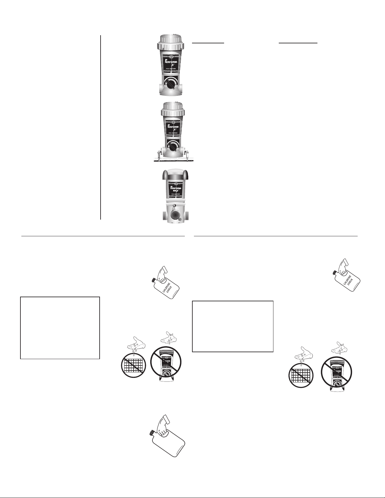
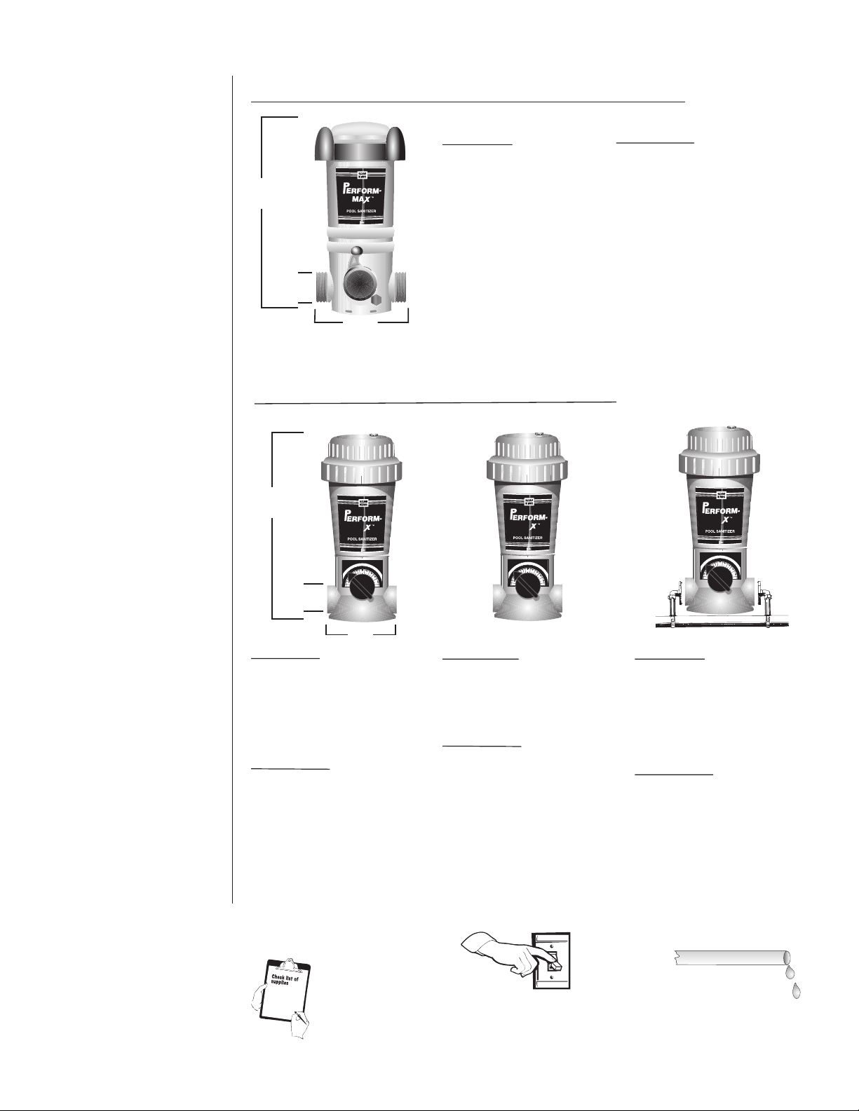
ABOVE GROUND POOLS •
Model #920
In-line for above ground
pools. Sanitizes up to
15 1/4"
1 1/2" i.d.
7 3/16"
IN GROUND POOLS •
25,000 gallons using
chlorine and up to 15,000
gallons using bromine.
See pages 7 and 9.
DO NOT INSTALL
OFF-LINE.
PISCINAS EN EL SUELO
PISCINAS SOBRE EL SUELO
Modelo #920
Dependiente para las
piscinas sobre el suelo.
Desinfecta hasta 25,000
galones – si utiliza cloro y
hasta 15,000 galones –
si utiliza bromo. Vea las
páginas 8 y 10. NO LO
INSTALE DE FORMA
AUTÓNOMA.
Instalación del
Perform-Max
TM
El Perform-Max viene en
varios modelos diferentes.
Por favor lea esta lista,
determine qué modelo tiene
y siga las instrucciones de
instalación apropiadas para
ese modelo únicamente.
Consejos para la
instalación
• No lo instalarle en un tubo
de cobre ya que se produce
corrosión.
• Usted puede supervisar
los galones por minuto
instalando un indicador de
flujo en la tubería de entrada.
•Vea las instrucciones del
fabricante para la instalación
del indicador de flujo.
17"
M
A
H
L
C
O
I
R
R
T
M
I
N
O
S
L
R
E
L
A
B
O
R
O
G
P
E
R
R
E
P
L
O
L
6
5
O
A
L
4
M
S
S
7
S
A
P
P
3
S
O
O
8
R
L
E
S
G
2
R
A
9
L
1
M
IN
X
A
2" I.D.
(Female
Threaded
M
7"
Model #940
In-line for in ground pools.
Sanitizes up to 50,000 gallons
using chlorine and up to 25,000
gallons using bromine. See
page 11.
DO NOT INSTALL OFF-LINE
Modelo #940
Dependiente para las piscinas
en el suelo (excavadas).
Desinfecta hasta 50,000
galones –si utiliza cloro y hasta
25,000 galones – si utiliza
bromo. Vea la página 12. NO
LO INSTALE DE FORMA
AUTÓNOMA.
M
A
H
L
C
O
I
R
R
T
M
I
N
O
S
L
R
E
L
A
B
O
R
O
G
P
E
R
R
E
P
L
O
L
6
5
O
A
L
4
M
S
S
7
S
A
P
P
3
S
O
O
8
R
L
E
S
G
2
R
A
9
L
1
M
IN
X
A
M
Model #980
In-line for in ground pools using
1 1/2" plumbing.
See page 17.
DO NOT INSTALL OFF-LINE.
Modelo #980
Dependiente para las piscinas
en el suelo (excavadas) que
utilizan tuberías de 1 1/2” Vea
la página 17. NO LO INSTALE
DE FORMA AUTÓNOMA.
M
A
H
L
C
O
I
R
R
T
M
I
N
O
S
L
R
E
L
A
B
O
R
O
G
P
E
R
R
E
P
L
O
L
6
5
O
A
L
4
M
S
S
S
7
A
P
P
3
S
O
O
8
R
L
E
S
G
2
R
A
9
L
1
M
IN
X
A
M
Model #960
Off-line for in ground or above
ground pools. Sanitizes up to
50,000 gallons using chlorine and
up to 20,000 gallons using bromine. See pages 13 & 14.
DO NOT INSTALL IN-LINE
.
Modelo #960
Desconectado para en el suelo
o encima de molió las piscinas.
Desinfecta hasta 50.000
galones – si utiliza cloro y hasta
20.000 galones – si utiliza
bromo. Vea las páginas 15 y
16. NO LO INSTALE DE
FORMA DEPENDIENTE.
Before installing
the Perform-Max, make
sure that:
Antes de instalar
Perform-Max,
asegúrese de que:
• You have all the
supplies.
• Tiene todos los
materiales.
• The pump is turned off.
• La bomba está apagada.
4
• The plumbing lines are dry.
• Las tuberías están secas.
Page 5
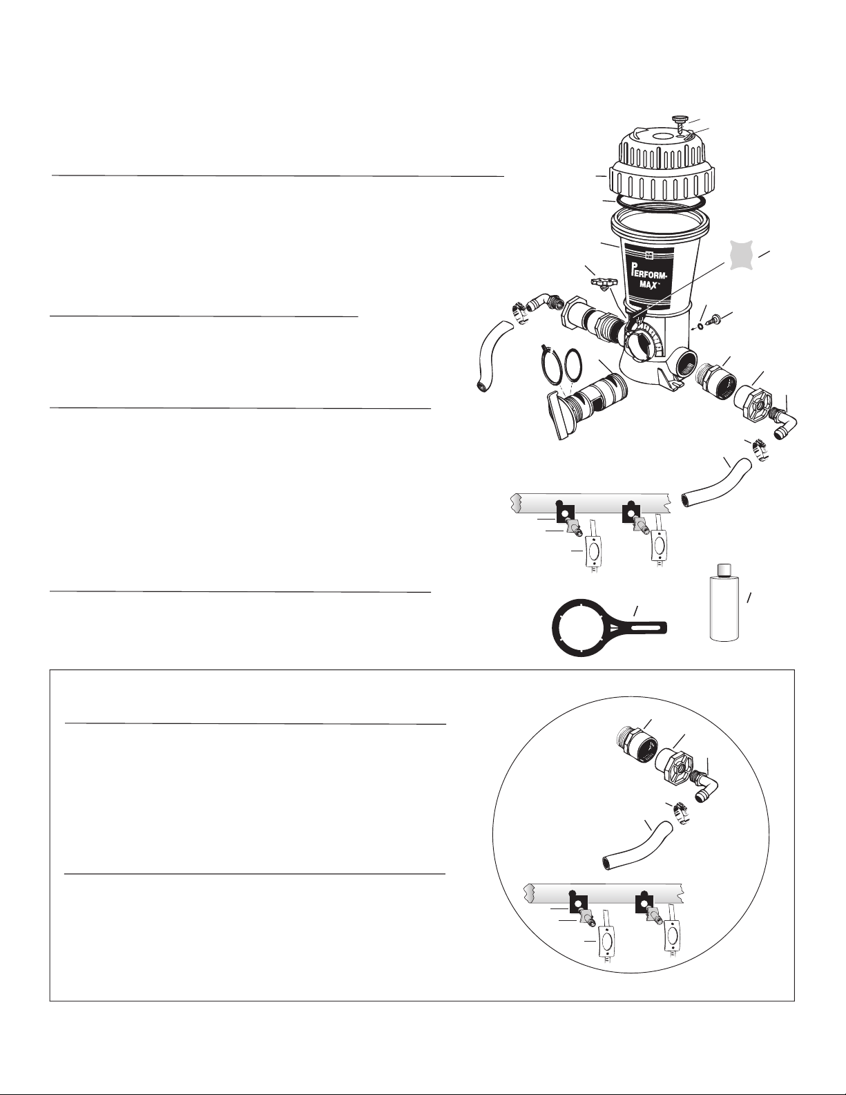
Parts List •
Above Ground Model 920
Lista de partes • Modele sobre la tierra 920
1
2
8 & 9
3
4
10
7
O
?
T
Y
H
P
E
R
O
C
S
I
E
L
I
N
C
O
L
U
T
B
N
R
A
I
C
13
C
OPY
C
OPY
C
O
P
Y
C
O
Y
P
11
6
5
Included with Above Ground Model 920
Incluido con Modela sobre la tierra 920
REF. # DESCRIPTION • DESCRIPCIÓN QTY. INC.
1 & 2 Cap w/O-Ring •
3 Body •
Cuerpo 1
4 Pressure Relief Valve •
Tapa c/anillo de cierre 1
Válvula de alivio de presión 1
5, 6, 7 Control Dial with O-Rings & Locking Pin
Comando de control con equipo de montaje 1
8 & 9 Knob with O-Ring •
10 Screen •
Pantalla 1
13 Silicone Lubricant •
Perilla con anillo de cierre 2
Lubricante de silicona 1
Replacement Parts for Above Ground Model 920
Los Repuestos para Modela sobre la tierra 920
REF. # ORDER # DESCRIPTION • DESCRIPCIÓN
1 & 2 01-22-1418 Cap w/O-Ring • Tapa c/anillo de cierre
2 01-22-1920 Cap O-Ring • Anillo de cierre de tapa
4 01-22-9480 Pressure Relief Valve • Válvula de alivio de presión
5, 6, 7 01-22-1443 Control Dial with O-Rings & Locking Pin
Comando de control con equipo de montaje
6 01-22-1450 Control Dial O-Ring Set
Kit de anillos de cierre del comando de control
8 & 9 01-22-9940 Knob with O-Ring • Perilla con anillo de cierre
10 01-22-9660 Screen • Pantalla
11 01-22-1710 Nipple Kit • Juego de pezón
12 01-22-1480 Mounting Base • La Base que monta
13 01-22-9971 Silicone Lubricant •
Lubricante de silicona
9
8
12
Optional part - not included
Opcional. No incluido.
5
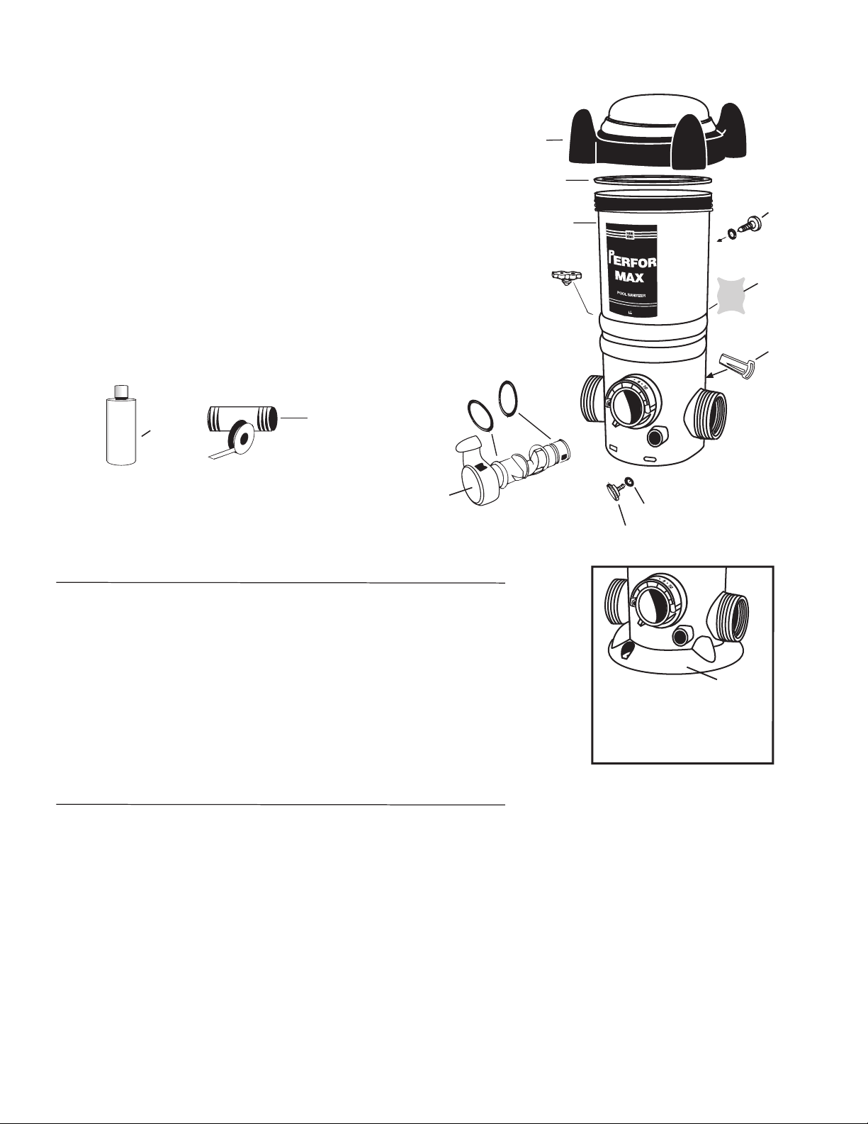
Page 6
Parts List • In Ground Models 940, 960, 980
Lista de partes • En Molió los Modelos 940, 960, 980
Included with Models 940, 960, 980 • Incluido con Ciclista 940, 960, 980
REF. # DESCRIPTION • DESCRIPCIÓN QTY. INC.
1 & 2 Cap w/O-Ring •
3 Body •
Cuerpo 1
4 Pressure Relief Valve •
5, 6, 7 Control Dial with Assembly Kit •
Comando de control con equipo de montaje 1
8 & 9 Knob with O-Ring •
10 Screen •
19 Cap/Control Dial Tool •
20 Silicone Lubricant •
For Models 980 • Para los modelos 980
Reducer Bushing 2” MPT x 1 1/2” FPT 2
Cojinete reductor 2” MPT x 1 1/2’ FPT
Replacment Parts for models 940, 960, 980
Los Repuestos para modelos 940, 960, 980
REF. # ORDER # DESCRIPTION • DESCRIPCIÓN
1 & 2 01-22-9411 Cap w/O-Ring • Tapa c/anillo de cierre
2 01-22-9920 Cap O-Ring • Anillo de cierre de tapa
4 01-22-9480 Pressure Relief Valve
5, 6, 7 01-22-9440 Control Dial with Assembly Kit
6 & 7 01-22-9450 Control Dial O-Ring Kit
8 & 9 01-22-9940 Knob with O-Ring • Perilla con anillo de cierre
10 01-22-9660 Screen • Pantalla
19 01-22-8870 Cap/Control Dial Tool • Llave de tapa / comando
20 01-22-9971 Silicone Lubricant • Lubricante de silicona
For Models 980 • Para los modelos 980
01-22-9820 Reducer Bushing 2” MPT x 1 1/2” FPT
Tapa c/anillo de cierre 1
Válvula de alivio de presión 1
Perilla con anillo de cierre 2
Pantalla 1
Llave de tapa / comando 1
Lubricante de silicona 1
Válvula de alivio de presión
Comando de control con equipo de montaje
Kit de anillos de cierre del comando de control
Cojinete reductor 2” MPT x 1 1/2’ FPT
4
7
6
16
17
18
8
9
1
2
3
P
O
O
L
S
A
N
I
T
I
Z
R
E
9
10
8
5
11
12
13
14
15
O
?
T
H
Y
E
P
R
O
C
20
S
I
E
L
I
N
C
19
O
L
U
T
B
N
R
A
I
C
C
O
P
Y
C
O
P
Y
C
O
P
Y
C
O
Y
P
OFF-LINE PARTS Included with Model 960 •
PARTES AUTÓNOMAS incluidas en las Modelo 960
REF. # DESCRIPTION • DESCRIPCIÓN QTY. INC.
11 2" Male Adaptor • Adaptador macho de 2” 2
12 2" x 1/2" Bushing • Cojinete de 2” x 1/2” 2
13 90 Degree Elbow • Codo de 90 grados 2
14 Small Clamp • Abrazadera chica 4 15
6' PVC Tubing •
Scoop Gasket •
Tubería de PVC de 6’ 1 16
Junta de cuchara 2
17 Venturi Scoop • Cuchara venturi 2 18
Scoop Clamp •
1Abrazadera de cuchara 2
Replacement Parts Model 960 • Los Repuestos para modelos 960
REF. # ORDER # DESCRIPTION • DESCRIPCIÓN
1
1 01-22-9490 2" Male Adaptor • Adaptador macho de 2”
12 01-22-8620 2" x 1/2" Bushing • Cojinete de 2” x 1/2”
13 01-22-7800 90 Degree Elbow • Codo de 90 grados
14 01-22-7690 Small Clamp • Abrazadera chica
15 01-22-7700 6' PVC Tubing • Tubería de PVC de 6’
16 01-22-7850 Scoop Gasket • Junta de cuchara
17 01-22-7790 Venturi Scoop • Cuchara venturi
18 01-22-7910 Scoop Clamp • 1Abrazadera de cuchara
6
OFF-LINE
PARTS 11 TO 18
16
17
18
11
12
13
14
15
Page 7
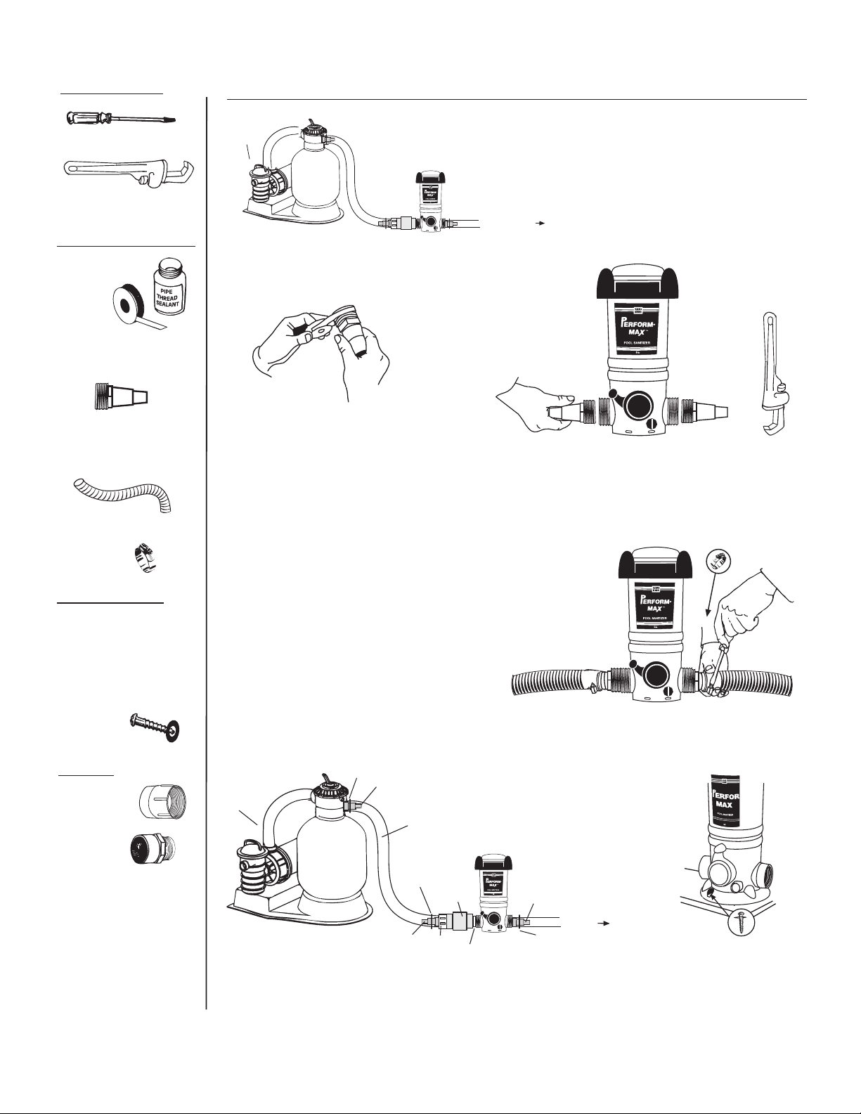
TOOLS NEEDED
Above Ground, Base Installation – Model 920
Screwdriver
Pipe Wrench
MATERIALS NEEDED
Pipe Thread
Tape or
Sealant
Two Hose Adapters
1 1/2" x 1 1/2" x 1 1/4"
Two Sections of
of 1 1/2" Flex Hose (one
provided with filter)
Two
Hose
Clamps
PUMP
FILTER
Apply pipe thread tape or
1.
sealant to the threaded end
of both hose adapters.
The Perform-Max should always be installed
between the filter and pool (or between
TO POOL
Screw adapters into each end of Perform-Max. Hand
2.
tighten. Finish tightening by turning 1 to 2 revolutions
heater and pool if applicable).
with wrench. DO NOT OVER TIGHTEN.
RECOMMENDED
Corrosion Resistant
Check Valve
#10 x 1 1/4" Phillips Pan
Head Screws with
Washers
OPTION
2” Female
Adapter
(slip x
FPT)
1 1/2" Male Adapter
(slip x MPT)
When installing with hard
PVC pipe, use either a
female adapter on the
outside port threads or
a male adapter on the
inside port threads.
Attach the filter section of flex
3.
hose to one hose adapter and
the return section of flex hose
to the other hose adapter with
clamps and tighten with
screwdriver.
HOSE
1 1/2" x 1 1/2" x 1 1/4"
CLAMP
HOSE ADAPTER
FILTER &
PUMP
4.
1 1/2" OR 1 1/4"
FLEX HOSE
HOSE
CLAMP
HOSE
ADAPTER
CHECK
VALVE
BUSHING
TOE NIPPLE
HOSE
ADAPTER
HOSE
CLAMP
TO POOL
Installing a corrosion resistant check valve is recommended for the
protection of pool equipment especially a heater, from chemical
corrosion.
5.
If you prefer to mount this unit
there is an additional base part
available - PN# 01-22-1480.
Mount using Phillips Pan head
screws.
7
Page 8
HERRAMIENTAS
NECESARIAS
Instalación básica sobre el suelo – Modelo 920
Destornillador
Llave inglesa
MATERIALES
NECESARIOS
Conduzca por
tubería el hilo
cinta
o sellador
Dos adaptadores de
manguera de
1 1/2” x 1 1/2” x 1 1/4”
Dos tramos de manguera
flexible de 1 1/2”
(uno con filtro)
Dos abrazaderas de
manguera
Bomba
1.
Filtro
Aplique conduzca por tuberia
el hilo cinta o sellador al
extremo enroscado de ambos
adaptadores de la manguera.
El Perform-Max siempre debe estar instalado
entre el filtro y la piscina (o entre el calentador
Hacia la
piscina
Atornille los adaptadores en cada extremo del
2.
Perform-Max. Apriete girando de 1 a 2 vueltas
y la piscina si
ese es el caso).
con la llave inglesa. NO APRIETE DEMASIADO.
SE RECOMIENDA
La corrosión válvula
resistente de cheque
Pernos de cabeza plana
Phillips #10 x 1 1/4” con
arandelas
OPCIÓN
2" Adaptador Femenino
(el tropiezo x FPT)
Adaptador macho de
1 1/2”
(slip x MPT)
Cuando instale un tubo
de PVC duro, use una
adaptador femenino en
las roscas del puerto
externo o un adaptador
macho en las roscas del
puerto interno.
Sujete con abrazaderas el tramo
3.
de filtrado de la manguera flexible
a un adaptador de manguera y
el tramo de retorno de la
manguera flexible al otro
adaptador de manguera y apriete
con destornillador.
ABRAZADERA
Filtro &
bomba
4.
DE MANGUERA
ADAPTADOR DE MANGUERA DE
1 1/2” x 1 1/2” x 1 1/4”
MANGUERA FLEXIBLE DE
1 1/2” O 1 1/4”
ABRAZADERA
DE MANGUERA
VÁLVULA
DE
CONTROL
ADAPTADOR DE
MANGUERA
COJINETE
PUNTERA DE
BOQUILLA
ADAPTADOR
DE MANGUERA
HACIA LA
PISCINA
ABRAZADERA DE
MANGUERA
Se recomienda instalar una válvula de control resistente a la corrosión
para proteger de la corrosión química al equipo de la piscina,
especialmente el calentador.
5.
Si usted prefiere montar esta
unidad hay una base adicional
despide #01-22-1480 disponible.
Monte los tornillos de
cabeza de Cacerola de Phillips
que utilizan.
8
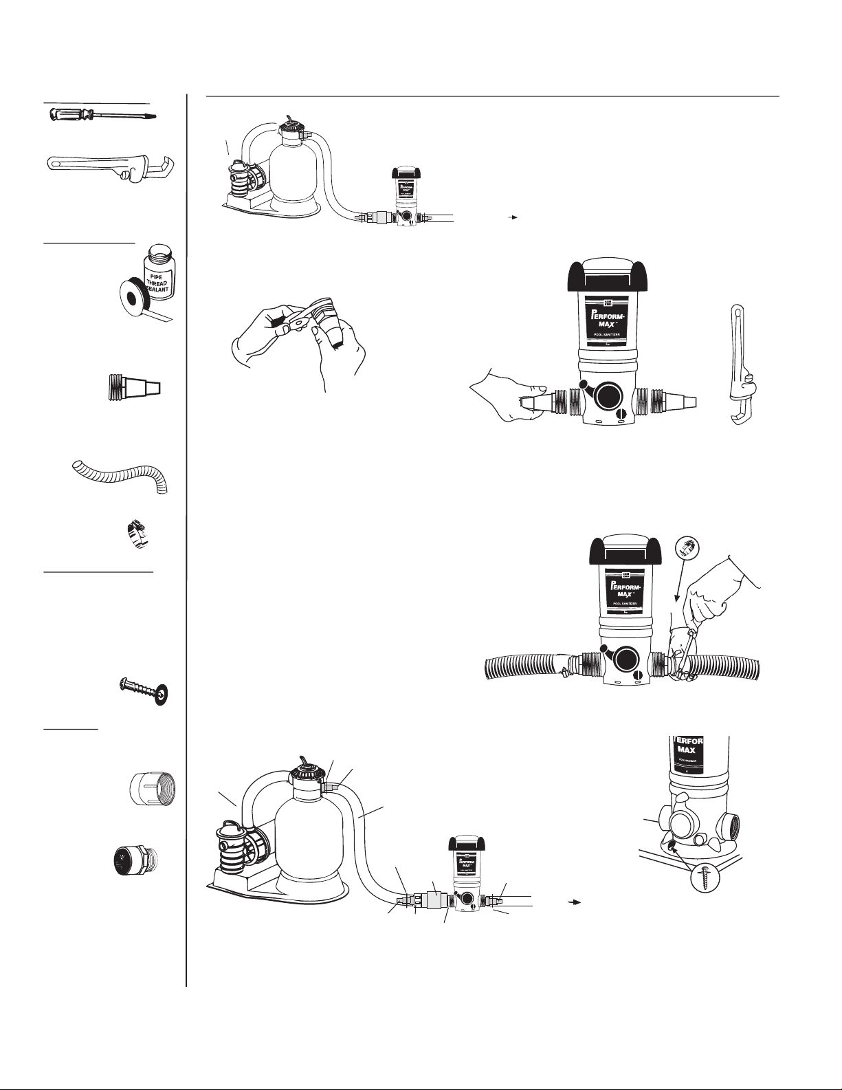
Page 9

TOOLS NEEDED
Screwdriver
Pipe Wrench
MATERIALS NEEDED
Pipe Thread
Tape or
Sealant
One 6" x 1 1/2" TBE PVC
Nipple
One Hose Adapter
1 1/2" x 1 1/2" x 1 1/4"
Above Ground, Filter Installation - Model 920
2.
Screw one end of nipple
1.
Apply pipe thread tape or
sealant to each threaded
end of nipple.
Apply pipe thread tape
4.
or sealant to threaded
end of hose adapter.
into the filter return.
Tighten turning
1 to 2 revolutions with wrench.
DO NOT OVER TIGHTEN.
Screw adapter into open end
5.
of Perform-Max. Hand tighten.
Finish tightening by turning
1 to 2 revolutions with wrench.
DO NOT OVER TIGHTEN.
Screw either side of
3.
Perform-Max on to open
nipple end until upright and
secure
.
One Section of
1 1/2" Flex Hose
(provided with filter)
One
Hose
Clamp
RECOMMENDED
Corrosion Resistant
Check Valve
HOSE ADAPTER
HOSE
ADAPTER
HOSE
ADAPTER
6.
Attach return section of hose to
the adapter with clamp. Tighten
clamp with screwdriver.
7.
Installing a corrosion resistant
check valve is recommended.
9
Page 10

HERRAMIENTAS
NECESARIAS
Destornillador
Instalación del filtro sobre el suelo – Modelo 920
Llave inglesa
MATERIALES
NECESARIOS
Conduzca por
tubería el hilo
cinta o sellador
Una boquilla de PVC TBE
de 6” x 1 1/2”
Un adaptador de manguera
de 1 1/2” x 1 1/2” x 1 1/4”
Un tramo de manguera
flexible de 1 1/2”
Aplique conduzca por tuberia
1.
el hilo cinta o sellador a cada
extremo enroscado de la
boquilla.
Aplique conduzca por tuberia
4.
el hilo cinta o sellador al
extremo enroscado de ambos
adaptadores de la manguera.
2.
Atornille un extremo de la
boquilla al retorno del filtro.
Apriete girando de 1 a 2 vueltas
con llave inglesa. NO APRIETE
DEMASIADO.
Atornille el adaptador en el extremo
5.
abierto del Perform-Max.
Apriete girando de 1 a 2
vueltas con la llave inglesa
NO APRIETE DEMASIADO.
.
Atornille cualquier lado del
3.
Perform-Max en el extremo
abierto de la boquilla hasta
que esté derecho y seguro.
Una abrazadera de
manguera
SE RECOMIENDA
La corrosión válvula
resistente de cheque
FILTRO Y
BOMBA
BOQUILLA DE 1
1/2” x 6”
ADAPTADOR DE MANGUERA DE
1 1/2” x 1 1/2” x 1 1/4”
ABRAZADERA
DE MANGUERA
ADAPTADOR DE
MANGUERA
10
MANGUERA FLEXIBLE DE
1 1/2” O 1 1/4”
ABRAZADERA
DE MANGUERA
COJINETE COJINETE
ABRAZADERA
DE MANGUERA
VÁLVULA DE
CONTROL
ADAPTADOR DE
MANGUERA
HACIA LA
6.
Sujete el tramo de retorno de
la manguera al adaptador con
una abrazadera. Apriete la
abrazadera con destornillador.
7.
Se recomienda instalar una
válvula de control resistente a
la corrosión.
Page 11

TOOLS NEEDED
Pipe Wrench
Hacksaw
MATERIALS NEEDED
Pipe Thread
Sealant
P
I
P
E
T
H
R
E
A
S
E
A
L
A
N
PVC
Cement
In Ground, In-line Installation – Model 940
M
A
L
H
O
C
I
R
R
T
I
M
N
O
R
E
B
L
S
A
R
L
O
G
O
E
P
R
R
4
P
E
O
L
L
S
O
6
5
A
L
A
S
P
M
7
S
S
P
3
R
O
E
O
8
G
L
R
S
A
2
L
9
1
M
I
N
X
A
M
I
nstall after all equipment and as far as possible from heater.
M
A
X
A
M
M
I
N
D
T
Do NOT install an in-line
Perform-Max off-line as this
Bi-flow valve design allows
water flow in either direction.
OR
6
5
4
7
P
3
O
O
8
L
S
2
9
1
X
A
M
M
A
6
5
4
7
P
3
O
O
8
L
S
2
9
1
M
I
N
AX
M
Perform-Max is different than an
off-line unit.
Do NOT install in copper pipe
as chemical corrosion occurs.
12" to 15"
Leave 12" to
15" above and
M
A
L
H
O
C
I
R
R
T
L
M
A
I
N
O
S
R
E
L
R
B
O
G
O
E
P
R
R
P
E
O
L
6
O
5
L
L
4
A
S
M
7
S
S
A
3
P
P
O
S
8
O
R
L
E
2
S
G
R
9
A
L
1
M
I
N
X
A
M
around
Perform-Max to
allow room for
easy refilling.
12" to 15"
Two 2" Threaded
x 2" or 1 1/2" Slip
PVC Bushings
(not included)
RECOMMENDED
Corrosion Resistant Check
Valve
#10 x 1 1/4" Phillips Pan
Head Screws with Washers
P
O
O
L
S
A
N
I
T
R
I
E
Z
1. 2. 3.
P
O
O
L
S
A
N
I
T
R
I
Z
E
Screw a bushing
into each port of
Perform-Max and
hand tighten.
Finish tightening
by turning 1 to 2
revolutions
with wrench.
DO NOT
OVER TIGHTEN.
Following pipe thread sealant
directions, brush sealant onto
Perform-Max threads in both
ports.
P
O
O
L
S
A
N
I
T
R
I
E
Z
Brush sealant on the
threads of both bushings.
DO NOT USE PIPE THREAD
TAPE as the threads
on these units
are not suitable
for this use and
leaking or bushing
failure could result.
M
A
C
L
H
O
I
R
R
T
M
O
I
N
E
R
B
L
S
A
L
R
O
G
O
E
P
R
R
P
E
O
L
O
L
5
6
A
L
S
M
4
S
A
7
P
S
P
S
3
O
R
O
E
8
L
G
S
R
2
A
L
9
1
M
I
N
X
A
M
Use Phillips pan head
screws through the
mounting holes at the
Perform-Max base to secure
the Perform-Max into a
treated wood base.
4.
Following PVC cement
directions, brush PVC cement
on to ends of pipe and the
inside of bushings.
5.
Insert PVC pipe into
bushings. Hold in place
5 to 10 seconds to bond.
11
I
6.
solating the Perform-Max by
installing a corrosion resistant
check valve or creating a
plumbing loop is recommended
to protect the equipment and
prevent possible discoloration
of pool surface.
Page 12

HERRAMIENTAS
NECESARIAS
Llave inglesa
Sierra de arco
Válvula de
control
M
A
H
L
O
I
C
R
R
T
M
I
N
O
E
R
B
L
S
A
L
R
O
G
O
E
P
R
4
R
P
E
O
L
S
O
L
6
5
A
A
L
P
S
7
M
S
S
R
P
3
E
O
O
8
G
L
R
S
A
2
L
9
1
X
A
M
M
I
N
Bomba
Filtro
Calentador (si
está instalado)
Instálelo después de todo el equipo y lo más lejos posible del
calentador.
NO lo instale en un tubo de
cobre ya que se produce
corrosión química.
12" to 15"
MATERIALES
NECESARIOS
Sellador de roscas
para tuberías
P
I
P
E
T
H
R
D
E
A
S
E
A
T
L
A
N
Cemento
de PVC
Dos roscas de 2” junto con
dos cojinetes de PVC de 2”
o 1 1/2” (no incluidos)
SE RECOMIENDA
La corrosión válvula
resistente de cheque
Pernos de cabeza plana
Phillips #10 x 1 1/4 ”
AX
M
NO instale un Perform-Max
dependiente en forma autónoma
ya que este Perform-Max es
M
A
4
3
2
1
M
I
N
o
6
5
7
P
O
O
8
L
S
9
AX
M
La válvula bidireccional permite
el flujo del agua en ambas
direcciones.
M
A
6
5
4
7
P
3
O
O
8
L
S
2
9
1
M
I
N
X
A
M
diferente de la unidad autónoma.
1. 2. 3.
P
O
O
L
S
A
N
I
T
R
I
Z
E
Atornille un cojinete en cada
puerto del desinfectante para
piscinas y apriete a mano.
Apriete completamente girando
de 1 a 2 vueltas con llave
inglesa. NO APRIETE
DEMASIADO.
Bomba
Siguiendo las instrucciones del
sellador de roscas para
tuberías, pase el sellador por
las roscas del Perform-Max en
ambos puertos.
P
O
O
L
S
A
N
I
T
R
I
E
Z
Pase el sellador por las roscas
de ambos cojinetes.
NO USE conduzca por
tubería el hilo cinta ya
que las roscas en
estos productos no son
apropiadas para este
uso y podría causar goteras o
fallas en los cojinetes.
M
A
L
H
O
C
I
R
R
T
L
M
A
I
N
O
S
R
E
L
R
B
O
G
O
E
P
R
R
P
E
O
L
6
O
5
L
L
4
A
S
M
7
S
S
A
3
P
P
O
S
8
O
R
L
E
2
S
G
R
9
A
L
1
M
I
N
X
A
M
12" to 15"
Filtro
Deje de 12” a
15” por encima
y alrededor del
Perform-Max
para que haya
espacio para
un fácil
rellenado.
Calentador (si
está instalado)
Válvula de
control
M
A
H
L
O
I
C
R
R
T
M
I
N
O
E
R
B
L
S
A
L
R
O
G
O
E
P
R
4
R
P
E
O
L
S
O
L
6
5
A
A
L
P
S
7
M
S
S
R
P
3
E
O
O
8
G
L
R
S
A
2
L
9
1
X
A
M
M
I
N
(Utilice los pernos de cabeza
plana Phillips a través de las
perforaciones mayores de la
base del Perform-Max para
asegurarlo a una base de
madera tratada). )
4.
Siguiendo las instrucciones del
cemento de PVC, pase
cemento de PVC en los
extremos del tubo y dentro de
los cojinetes.
5.
Coloque el tubo de PVC dentro
de los cojinetes. Sosténgalo en
ese lugar de 5 a 10 segundos
para adherirlo.
12
Se recomienda aislar el Perform-
6.
Max instalando una válvula de
control resistente a la corrosión
o crear un bucle en la tubería
para proteger el equipo y
prevenir una posible
decoloración de la superficie de
la piscina.
Page 13

TOOLS NEEDED
Pipe Wrench
Screwdriver
Battery
Operated Drill
with 5/8" or 19/32" Bit.
MATERIALS NEEDED
Pipe Thread
Sealant
P
I
P
E
T
H
R
D
E
A
S
E
A
L
A
PVC
N
Cement
Off-line Installation – Model 960
When insufficient room for an in-
SCOOPS
2” - 36”
APART
M
A
C
H
L
O
I
R
R
T
M
N
O
I
E
R
B
L
S
A
L
R
O
G
O
E
P
R
R
P
E
O
L
O
L
A
L
S
M
S
4
S
A
5
6
P
S
7
R
3
E
P
G
O
8
R
O
A
L
L
S
2
9
1
M
I
N
X
A
M
M
A
L
H
O
C
I
R
R
T
M
I
N
O
R
E
B
L
S
A
L
R
O
G
O
E
P
R
R
P
E
O
L
O
L
A
L
S
M
S
4
S
A
6
5
P
S
7
R
3
E
P
G
O
8
R
O
A
L
L
S
2
9
1
MIN
X
A
M
T
Max in-line as this Perform-Max
Do NOT install an off-line Perform-
Bi-flow valve design allows water flow in either direction.
M
A
H
C
L
O
I
R
R
T
M
I
N
O
R
E
B
L
S
A
L
R
O
G
O
E
P
R
R
P
E
O
L
L
O
A
L
S
M
S
4
S
6
5
A
P
S
7
R
3
E
P
O
G
8
O
R
L
A
S
2
L
9
1
M
I
N
X
A
M
is different than an in-line unit.
line application, install off-line in
straight pipe with scoops
between 2” - 36” apart. Install as
far from heater as possible.
OR
M
A
H
C
L
O
I
R
R
T
M
I
N
O
R
E
B
L
S
A
L
R
O
G
O
E
P
R
R
P
E
O
L
L
O
A
L
S
M
S
4
S
6
5
A
P
S
7
R
3
E
P
O
G
8
O
R
L
A
S
2
L
9
1
M
I
N
X
MA
OFF-LINE KIT
Included with 960
Two Male
Adapters
Two Reducer
Bushings
Two
90 Degree Elbows
Four Hose Clamps
6' of Tubing
Two
Scoops
Two Scoop
Gaskets
Two Scoop
Clamps
1.
P
I
P
E
T
H
R
D
E
A
S
E
A
L
T
A
N
P
O
O
L
S
A
N
I
T
I
Z
E
R
Following pipe thread sealant
directions, brush sealant onto
Perform-Max threads in both ports.
P
O
O
L
S
A
N
I
T
R
I
E
Z
2.
P
I
P
E
T
H
R
D
E
A
S
E
A
T
L
A
N
Brush sealant on threads of both
male adapters.
DO NOT USE PIPE THREAD
TAPE as the threads on
these units are
not suitable for
this use and
leaking or bushing
failure could result.
P
O
O
L
S
A
N
I
T
I
Z
E
R
3.
P
O
O
L
S
A
N
I
T
R
I
Z
E
Screw a male
adapter into each
port of Perform-Max and
hand tighten.
Finish tightening
by turning 1 to 2
revolutions
with a wrench.
DO NOT
OVERTIGHTEN.
RECOMMENDED
Corrosion Resistant
Check Valve
#10 x 1 1/4" Phillips Pan
Head Screws with Washers
4.
Following PVC cement
directions, brush PVC cement
on reducer bushings and inside
of male adapters.
5.
I
nsert reducer bushing into male
adapter on both sides. Hold in
place 5 to 10 seconds to bond.
13
P
I
P
E
T
H
R
D
E
A
S
E
A
T
L
A
6.
N
Following pipe thread sealant
directions, brush sealant onto
elbow threads.
Page 14

7. 8. 9. 10.
When pipe is
totally dry,
drill two 19/32"
or 5/8" holes
between 2” - 36”
apart on the return
line. Be careful not to
go through other side
of pipe.
P
O
O
L
S
A
N
I
T
I
Z
E
R
Screw elbow into reducer
bushings on both sides.
Cut tubing
to size for
each
PerformMax
connection
and attach
one to each
elbow with
clamps.
P
O
O
L
S
A
N
I
T
I
Z
E
R
P
O
O
L
S
A
N
I
T
I
Z
E
R
Tighten clamps
with a screwdriver.
11. 12. 13.
2" - 36" apart on straight pipe
Place scoops
inside holes so
the inlet scoop
faces the water
flow and the
Arrows on scoops must face each other.
outlet scoop
faces away from
Attach a gasket to
the water flow.
each scoop.
14.
15.
16.
Attach each hose to a
Tighten scoop clamps with a
screwdriver.
venturi scoop male nipple
with a small clamp and
tighten with screwdriver.
P
O
O
L
S
A
N
I
T
I
Z
E
R
For best results use Phillips pan
head screws through the
mounting holes at the PerformMax base to secure the PerformMax into a treated wood base.
Attach scoop clamps over
the scoops and around the
pipe.
P
O
O
L
S
A
N
I
T
R
I
E
Z
17.
SCOOPS
2" - 36"
APART
M
A
H
L
I
C
O
R
R
T
M
I
N
O
E
R
B
L
S
A
L
R
O
G
O
E
P
R
R
P
E
O
L
L
O
A
L
S
S
M
4
A
S
5
6
P
S
7
R
E
3
G
P
O
8
R
O
A
L
L
2
S
9
1
M
I
N
X
A
M
I
solating the Perform-Max by installing a corrosion resistant check
valve is recommended to protect the equipment and prevent
discoloration of pool surface.
14
Page 15

HERRAMIENTAS
NECESARIAS
Llave inglesa
Destornillador
Taladro a baterías con
broca de 5/8” o 19
/32”
MATERIALES
NECESARIOS
Sellador de
roscas para
tuberías
P
I
P
E
T
H
R
D
E
A
S
E
A
L
T
A
N
Cemento
de PVC
EQUIPO AUTÓNOMO
• Incluido en el modelo
960
• Dos
adaptadores macho
• Dos cojinetes
reductores
• Dos codos de
90 grados
• Cuatro abrazaderas
de manguera
• 6’ de tubería
• Dos cucharas
• Dos juntas de
cuchara
• Dos
abrazaderas
de cuchara
Instalación autónoma – Modelo 960
válvula de
bomba
filtro
calentador (si
está instalado)
M
A
L
H
O
C
I
R
R
T
M
I
N
O
R
E
B
L
S
A
L
R
O
G
O
E
P
R
R
P
E
O
L
O
L
A
L
S
M
S
4
S
A
6
5
P
S
7
R
3
E
P
G
O
8
R
O
A
L
L
S
2
9
1
MIN
X
A
M
NO instale un Perform-Max
autónomo en forma dependiente
ya que este Perform-Max es
diferente de la unidad dependiente.
1.
P
I
P
E
T
H
R
D
E
A
S
E
A
L
T
A
P
O
O
L
S
A
N
I
T
I
Z
E
R
Siguiendo las instrucciones del
sellador de roscas para tuberías,
pase el sellador por las roscas del
Perform-Max en ambos puertos.
P
O
O
L
S
A
N
I
T
R
I
E
Z
N
control
M
A
H
C
L
O
I
R
R
T
M
I
N
O
R
B
S
L
O
O
P
R
E
L
L
A
M
S
4
S
6
5
A
P
S
7
R
3
E
G
R
A
2
L
1
M
I
N
La válvula bidireccional permite el flujo del agua en ambas
direcciones.
2.
Pase el sellador en las roscas
de ambos adaptadores macho.
NO USE conduzca por
tubería el hilo cinta ya que las
roscas en estos
productos no son
apropiadas para
este uso y podría
causar goteras o fallas en los
cojinetes.
M
A
C
H
L
O
I
R
R
T
M
N
O
I
E
R
B
L
S
A
L
R
O
G
O
E
P
R
R
P
E
O
L
O
L
A
L
S
M
S
4
S
A
5
6
P
S
7
R
3
E
P
G
O
8
R
O
A
L
L
S
2
9
1
M
I
N
X
A
M
E
L
A
R
G
E
R
P
O
O
L
S
P
O
8
O
L
S
9
X
A
M
cucharas con
2" - 36" de
separación
P
I
P
E
T
H
R
D
E
A
S
E
A
T
L
A
N
Puede ser instalado en
cualquiera en el suelo o encima
de la piscina del suelo que se
plumbed con tubo duro de pvc.
Utilice cuando hay el espacio
insuficiente para una aplicación
de la en-línea. Instale como lejos
de la calentadora como posible.
M
o
P
O
O
3.
L
A
H
C
L
O
I
R
R
T
M
I
N
O
R
E
B
L
S
A
L
R
O
G
O
E
P
R
R
P
E
O
L
L
O
A
L
S
M
S
4
S
6
5
A
P
S
7
R
3
E
P
O
G
8
O
R
L
A
S
2
L
9
1
M
I
N
X
MA
S
A
N
I
T
R
I
Z
E
Atornille un adaptador
macho en cada puerto del
Perform-Max y apriete a
mano.
Apriete completamente
girando de 1 a 2
vueltas con una
llave inglesa. NO
APRIETE
DEMASIADO.
SE RECOMIENDA:
La corrosión válvula
resistente de cheque
Pernos de cabeza
plana Phillips #10 x 1 1/4”
con arandelas
4.
Siguiendo las instrucciones del
cemento de PVC, pase cemento
de PVC en los cojinetes
reductores y dentro de los
adaptadores macho.
P
O
O
L
S
A
N
I
T
I
Z
E
R
5.
Coloque el cojinete reductor
dentro del adaptador macho en
ambos lados. Sosténgalo en
ese lugar de 5 a 10 segundos
para adherirlo.
15
P
I
P
E
T
H
R
D
E
A
S
E
A
T
L
A
6.
N
Siguiendo las instrucciones del
sellador de roscas para
tuberías, pase el sellador en las
roscas del codo.
Page 16

7. 8. 9. 10.
Cuando el tubo
esté totalmente seco,
haga dos perforaciones
de 19/32” o 5/8” a 2" 36" de separación en la
línea de retorno. Tenga
cuidado de no pasar del
otro lado del tubo.
P
O
O
L
S
A
N
I
T
I
Z
E
R
Atornille el codo en los
cojinetes reductores en ambos
lados.
Corte la
tubería a
medida para
cada
conexión del
Perform-Max
y fíjela a cada
codo con
abrazaderas.
P
O
O
L
S
A
N
I
T
I
Z
E
R
P
O
O
L
S
A
N
I
T
I
Z
E
R
Ajuste las abrazaderas
con un destornillador.
11. 12. 13.
Ubique las
cucharas dentro
de las
perforaciones
Sujete una junta a cada
cuchara.
14.
Ajuste las abrazaderas de la
cuchara con un destornillador.
17.
Bomba
Filtro
Calentador (si
está instalado)
para que la
cuchara de
entrada esté de
frente al flujo de
agua y la cuchara
de salida mire
para el otro lado
del flujo de agua.
P
O
Válvula de
Control
Las flechas en las cucharas deben
enfrentarse una a la otra.
15.
Sujete cada manguera a una
boquilla macho de la cuchara
venturi con una pequeña
abrazadera y ajuste con el
destornillador.
O
L
S
A
N
I
T
I
Z
E
R
Cucharas con
2" - 36" de
M
A
H
L
I
C
O
R
R
T
M
I
N
O
E
R
B
L
S
A
L
R
O
G
O
E
P
R
R
P
E
O
L
L
O
A
L
S
S
M
4
A
S
5
6
P
S
7
R
E
3
G
P
O
8
R
O
A
L
L
2
S
9
1
M
I
N
X
A
M
separación
Se recomienda aislar el Perform-Max instalando una válvula
de control resistente a la corrosión para proteger el equipo y
prevenir la decoloración de la superficie de la piscina.
16.
Para mejores resultados use
pernos de cabeza plana Phillips
a través de las perforaciones
mayores de la base del PerformMax para asegurarlo a una base
de madera tratada.
Sujete las abrazaderas
de las cucharas sobre
éstas y alrededor del
tubo.
P
O
O
L
S
A
N
I
T
R
I
E
Z
16
Page 17

For Proper Performance • Para un rendimiento adecuado
1) Recommended flow
rates for in ground unit is
20-80 gpm and for above
ground unit is 20-60 gpm.
2) Make sure back
pressure Is between 3
and 8 psi
Higher back pressures
result in over chlorination.
Lower back pressures result
in under chlorination. Adjust
eye ball fittings in the return
jets to a larger size to
decrease back pressure or
smaller size to increase
back pressure.
3) Determine possible
high-flow situations that
require a special
installation such as:
A. Water flow is higher than
80 gpm.
B. In-floor cleaner is included
with pool.
C. Pool and spa combination
with common equipment.
NOTE: Over chlorination or
damage to the Perform-Max
or other equipment could
result if these special
installations are not used in
these situations.
1) El índice de flujo recomendado
para una unidad dentro del suelo
es de 20-80 galones por minuto
(74,95-302 litros por minuto) y para
una unidad sobre el suelo es de
20-60 galones por minuto (74,95227,17 litros por minuto).
2) Asegúrese de que la presión de
fondo esté entre las 3 y 8 libras
por pulgada cuadrada (1.36 a 36.32
kg por cm
2
)
Una contrapresión mayor provoca
sobrecloración. Una contrapresión
menor provoca baja cloración. Ajuste
las instalaciones en los reactores a
un mayor tamaño para bajar la
contrapresión o a un menor tamaño
para aumentar la contrapresión.
3) Determine las posibles
situaciones de alto flujo que
requieren una instalación especial:
A. El flujo de agua es mayor a 80
galones por minuto (302 litros por
minuto)
B. El limpiafondo está incluido en la
piscina.
C. La piscina y el spa tienen un
equipo en común.
NOTA: Se puede provocar una
sobrecloración o dañarse el PerformMax u otro equipo si estas
instalaciones especiales no se usan
en estas situaciones.
A. With High GPMS Install T- fittings as shown only.
A. CON ÍNDICES DE LITROS POR
MINUTO ALTOS instale accesorios T
PERFORM-MAX
exactamente como se muestra
SUCTION
FROM
POOL/SPA
SUCCIÓN DESDE
LA PISCINA
PISCINA/SPA
B. With In-floor Cleaners
B. Con limpiafondos
NOTE: The best
option is to have a
separate pump for the
Bomba
§
Filtro
3-WAY MANUAL VALVE OR 3-WAY MOTOR
VALVE CONTROL
La VALVULA O 3-WAY MANUALES de 3
MANERAS el CONTROL MOTRIZ de VALVULA
§§
§
§
in-floor cleaning
system.
La NOTA: La mejor
Bomba
opción deberá tener una bomba separada
para el en-piso que limpia sistema.
Filtro
§
§
§
Válvula de
control
§
PERFORM-
M
A
MAX
C
L
I
H
O
R
R
T
I
M
N
O
R
E
B
S
L
O
O
P
R
E
L
L
6
5
A
S
A
4
M
7
P
P
S
S
O
3
O
R
8
L
E
S
G
R
2
A
L
9
1
M
I
N
X
A
M
§
§
Nivel de agua de la
§
§
§
§
§
§
§
C. Pool and Spillover Spa Combination
C. Combinación de piscina y spa indirecto
3 válvula de manera
3-WAY VALVE
TO POOL
Hacia el spa
TO SPA
Hacia la piscina
SUCTION
FROM
POOL/SPA
Succión desde
la piscina –
piscina/spa
Bomba
PERFORM-MAX
Válvula de control
CHECK VALVE
Filtro
TO POOL
Hacia la
piscina
IN-FLOOR
VALVE
Válvula
de fondo
piscina
In-line Installations for 1 1/2" Plumbing
Instalaciones dependientes para tuberías de 1 1/2”
Perform-Max 980
• If installing a Model 980
Perform-Max, follow steps 1
through 3 on page 11 using the
reducer bushing included with
the Model 980.
Repeat steps 1 through 3
using a 1 1/2" threaded
by 1 1/2" slip bushing
(you provide).
Then follow the remaining inline
directions on page 11.
M
A
H
L
C
O
I
R
R
T
L
S
A
M
I
N
O
L
R
R
E
O
B
G
O
E
P
R
E
L
L
6
5
A
M
4
S
S
7
A
P
3
S
8
R
E
G
2
R
A
9
L
1
M
IN
A
M
Model 980
R
P
O
O
L
S
P
O
O
L
S
X
Perform-Max 980
• Si instala un Perform-Max modelo
980, siga los pasos del 1 al 3 en la
página 12 utilizando el cojinete reductor
incluido con el modelo 980.
Repita los pasos del 1 al 3 utilizando
una rosca de 1 1/2” junto con un cojinete
de 1 1/2” (que usted provee).
Después, siga las instrucciones
restantes para la instalación dependiente
en la página 12.
17
• Two 2" Threaded by
1 1/2" Threaded
Bushings (included)
• Dos roscas de 2” junto
con dos cojinetes de
1 1/2” (incluidos)
• Two 1 1/2" male adapters
(slip x mpt)
(you provide)
• Dos 1 1/2" adaptadores
masculinos (mpt de
tropiezo x) (que usted
provee)
Page 18

Refilling Chemicals
CAUTION Read Carefully
USE ONLY ...
Slow dissolving trichloro-s-triazinetrione (trichlor) tablets or pucks
or bromine tablets or sticks in the Perform-Max.
NEVER MIX CHEMICALS
S
L
O
O
P
R
E
L
1.
Turn pump off.
L
A
M
S
S
A
P
S
R
E
G
2
R
A
L
1
m
in
i
m
u
m
Models 940, 960, 980
2.
Turn dial to Minimum or Setting
6
5
4
3
Model 920
0. This reduces the flow of water
into the unit when the cap is
open so isolation valves are
unnecessary.
Remove cap and
4.
immediately stand
back to avoid inhaling fumes.
For models 940, 960 & 980
use the cap tool included to
loosen cap by hitting the
handle with the flat of your
Models 940,
960, 980
hand counterclockwise.
No tool needed
for Model 920.
DO NOT USE ...
CALCIUM HYPOCHLORITE, FAST DISSOLVING TRICHLOR
OR ANY GRANULAR OR LIQUID MATERIAL IN THE
PERFORM-MAX.
USE OF THESE PRODUCTS COULD RESULT IN FIRE
OR EXPLOSION
3.
Model 920
Models 940, 960, 980
Unscrew knob in back of Model 920 or cap knob on Models 940, 960
and 980 to relieve pressure.
Fill unit to top with either recommended
5.
chlorine or bromine. DO NOT MIX
BROMINE AND CHLORINE. Do not
put small particles in feeder. Always wear
protection for eyes, skin and clothing.
M
A
H
L
O
C
I
R
R
T
L
M
I
O
N
A
S
R
E
L
R
B
G
O
O
E
P
R
R
P
E
O
L
6
5
O
L
L
4
A
S
7
M
S
S
A
3
P
P
O
S
8
O
R
L
E
2
S
G
R
A
9
L
1
M
I
N
X
A
M
Avoid sparks, open flame or smoking
when handling chemicals.
6.
Replace cap by hand only. DO NOT OVER TIGHTEN.
7.
DO NOT USE CAP TOOL to
Models 940, 960, 980
Replace knob.
tighten cap. For removal only.
Changing by Types of Chemicals (i.e. switching from bromine to chlorine)
6
5
4
7
8
9
M
U
IM
X
A
M
Models 940, 960, 980 Model 920
Models 940, 960, 980
1.
Operate Perform-Max until
empty of all chemical. When
empty, set control dial to maximum or Setting 10 and let run
empty 24 hrs.
2.
Turn pump off.
Model 920
3.
Unscrew knob in back of Model 920 or on cap of Models 940,
960 & 980 to relieve pressure.
18
Model 920
Page 19

Changing Chemicals
5.
Make sure all
small particles have
dissolved and been
To loosen cap hit the
handle with the flat of your
hand counterclockwise-
No tool
needed for
Model 920.
Models 940, 960 & 980.
4.
Remove cap and immediately
stand back to avoid inhaling
fumes.
flushed out of
feeder. Fill unit with
new chemical.
DO NOT MIX
BROMINE AND
CHLORINE. Do not
put small particles in feeder
continued
.
Always wear protection for eyes, skin & clothing. Avoid sparks, open flame or smoking when handling chemicals.
M
A
L
H
C
I
O
R
R
T
M
L
I
N
O
A
R
S
E
L
R
B
G
O
O
E
P
R
R
P
E
O
L
6
O
5
L
L
4
A
S
7
M
S
S
A
P
3
P
S
O
8
O
R
L
E
2
S
G
R
A
9
L
1
M
I
N
X
A
M
6.
Replace cap by hand only.
DO NOT OVER TIGHTEN.
Do not use cap tool to tighten
cap. For removal only.
Models 940, 960, 980
7.
Replace knob.
8.
For proper initial setting
Model 920
continue to next section: Setting
Control Dial.
Setting Control Dial
To start...
When using slow dissolving trichlor, the Perform-Max should be operated based on its normal erosion design where
only the bottom layer of tablets are wetted. This provides better controllability and longer lasting sanitation per refill.
When using bromine, the Perform-Max should be operated as a soaking feeder as this chemical works best when
all tablets are wetted. Therefore bleeding the air on these units is recommended when using bromine.
Models 940, 960, 980
1.
For all pools using chlorine...... set the control dial at #2.
2.
For the first
week or so, test
the water daily
for free chlorine
or bromine.
l
o
P
o
a
d
n
S
a
p
t
T
s
e
s
p
S
i
r
t
3.
After day one, adjust the dial
up by 1/2 increment if the reading
has dropped or down by 1/2 increment if the reading has risen.
Continue this process each day
until the reading stabilizes at your
desired level between 1.0 and 3.0
ppm.
If under chlorinating •
Begin with Option 1 and continue with other options if necessary
Model 920
Models 940, 960, 980
Model 920
For all pools using bromine ......set the control dial at #4. With
bromine only, bleed air from unit by partially unscrewing back knob
on Model 920 or cap knob on Models 940, 960 & 980 while the pump
is running until water appears. Tighten knob.
Models 940, 960, 980
Model 920
4.
For
Models 940,
960 & 980
M
A
use the
Remember to adjust dial by 1/2
increments only. Higher than suggested settings could result in over
chlorination and/or bleached pool
S
L
O
O
P
R
E
L
L
A
M
S
S
A
P
S
R
E
G
2
R
A
L
1
M
I
N
L
H
O
C
I
R
R
T
L
M
I
A
N
O
E
R
R
B
G
E
R
P
O
O
5
6
L
S
4
7
P
3
O
O
8
L
S
9
X
A
M
handle end of
cap tool if the
dial is hard to
turn.
surfaces.
OPTION 1 OPTION 2 OPTION 3
Increase the
number of
hours your
pump runs
per day.
If reading dropped below 1.0 ppm, shock pool.
Turn control dial to minimum when shocking
and NEVER ADD SHOCK IN OR NEAR THE
SKIMMER. Reset dial 1/2 setting higher than
before and continue monitoring daily until
desired chemical level is acheived.
Switch from
3 inch pucks
to 1 inch tablets.
OPTION 4
Try bleeding the air,
soaking tablets for
greater output.
If over chlorinating •
Begin with Option 1 and continue with other options if necessary
OPTION 3OPTION 2OPTION 1
Decrease the
number of hours
your pump runs
per day. Water
must circulate fully
once a day.
Troubleshooting:
Contact your dealer or King Technology’s Customer Service Department at 800-222-0169, if the steps below do not solve the situation.
Turn dial to minimum or
Setting 0. When reading
drops to desired ppm, reset
dial 1 setting lower than the
starting dial setting and
continue monitoring daily.
6
5
4
S
A
P
3
S
R
E
G
2
R
A
L
1
m
in
i
m
u
m
Models 940, 960, 980
Switch from
1 inch tablets
to 3 inch pucks.
Model 920
19
Page 20

Cómo rellenar los productos químicos
PRECAUCIÓN lea detenidamente
UTILICE SOLAMENTE...
Tabletas o discos de tricloro-s-triazinetrione (tricloro) de lenta
disolución o tabletas o varas de bromo en el Perform-Max. NUNCA
MEZCLE LOS PRODUCTOS QUÍMICOS.
S
L
O
O
P
R
E
L
L
A
M
S
S
A
P
S
R
E
G
2
R
A
L
1
m
i
n
im
u
m
6
5
4
3
NO UTILICE...
Hipoclorito de calcio, tricloro de rápida disolución o cualquier
material líquido o en gránulos.
en el perform-max. El uso de estos productos podría provocar
un incendio o explosión.
1.
Apague la bomba
4.
Quite la tapa e inmediatamente
soporte para evitar atrás
vapores que inhalan. Para
modelos 940, 960 & 980 uso el
instrumento de la tapa incluyó
para aflojar la tapa golpeando
el asidero con el plano de la
mano a la izquierda.
Modelos 940, 960, 980
Modelo 920
2.
Coloque el comando de control
al mínimo o colocación. Esto
reduce el flujo de agua dentro
de la unidad cuando la tapa está
abierta, por lo tanto no se
necesitan las válvulas de
aislamiento.
Modelos 940,
960, 980
Ningún instrumento
necesitó para Modelo
920.
3.
Modelo 920
Modelos 940, 960, 980
Destornille la perilla detrás del Modelo 920 o la perilla de la tapa
en Modelos 940, 960 y 980 en aliviar la presión.
Llene la unidad hasta el tope
5.
con el producto químico. NO
MEZCLE EL BROMO CON EL
CLORO. No coloque partículas
pequeñas en el alimentador.
M
A
Siempre utilice protección para
los ojos, la piel y la ropa. Evite
hacer chispas, llamaradas o
L
H
C
O
I
R
R
T
L
M
I
N
O
A
S
R
E
L
R
B
O
G
O
E
P
R
R
P
E
O
L
6
5
O
L
L
4
A
S
7
M
S
S
A
3
P
P
S
O
8
O
R
L
E
2
S
G
R
A
9
L
1
M
I
N
X
A
M
fumar cuando esté usando
productos químicos.
7.
6.
Modelos 940, 960, 980
Vuelva a poner la tapa a mano solamente. NO APRIETE
DEMASIADO.
Cómo cambiar los productos químicos
6
5
4
7
8
9
M
U
IM
X
A
M
Modelos 940, 960, 980 Modelo 920
1.
Utilice el Perform-Max hasta
que no queden productos químicos. Cuando esté vacío, coloque
el comando de control al máximo
o colocación 10 y déjelo funcionar vacío durante 24 hrs.
Modelo 920
2.
Apague la bomba.
NO UTILICE LA LLAVE DE
TAPA para apretar la tapa. Sólo
para retirarla.
3.
Modelos 940, 960 & 980 en aliviar la presión.
20
Modelos 940, 960, 980
Modelo 920
Reemplace la perilla.
Model 920
Models 940, 960, 980
Destornille la perilla detrás del Modelo 920 o en la tapa de
Page 21

Cómo cambiar los productos químicos
(continuación)
Siempre lleve la protección para ojos, la piel y la ropa. Evite las chispas, abra la llama o fumando al manejar sustancias químicas.
5.
Cerciórese todas
partículas pequeñas
se han disuelto y
Para aflojar el golpe de la
tapa el asidero con el plano
de sus a la izquierda-modela
de mano 940, 960 & 980.
4.
Quite la tapa e
Ningún
instrumento
necesitó para
el Modelo 920.
inmediatamente soporte para
evitar atrás vapores que
inhalan.
Cómo programar el comando de control
Para comenzar...
fueron limpiado
fuera de
alimentador. Llene
la unidad con nueva
sustancia química.
No MEZCLE BROMO Y
CLORO. No ponga las
partículas pequeñas en el
alimentador
Afloje cuando se usa disolver trichlor, el Realiza-Max debe ser operado basado en su diseño normal de la erosión donde sólo la capa
inferiora de tabletas se moja. Esto proporciona mejor controllability y durar más largo el saneamiento por rellena. Cuando se usa bromo,
el Realiza-Max debe ser operado como un alimentador empapado como estes trabajo de sustancia química mejor cuando todas tabletas
se mojan. Por lo tanto sangrando el aire en estas unidades se recomienda cuando se usa bromo.
Modelos 940, 960, 980
M
A
L
H
C
I
O
R
R
T
M
L
I
N
O
A
R
S
E
L
R
B
G
O
O
E
P
R
R
P
E
O
L
6
O
5
L
L
4
A
S
7
M
S
S
A
P
3
P
S
O
8
O
R
L
E
2
S
G
R
A
9
L
1
M
I
N
X
A
M
Model0 920
6.
Reemplace la tapa a mano
sólo. HAGA no SOBRE
APRIETA. No utilice
instrumento de tapa para
apretar la tapa. Para la
eliminación sólo.
Para todas
piscinas que
Modelos 940, 960, 980
utilizan bromo
...set la esfera
del control en
#4. Con bromo
sólo, sangra aire de la unidad por destornillar parcialmente atrás
1.
Para todas las piscinas que utilizan cloro......programe
el comando de control en #2.
2.
Durante la
primera semana
aproximadamen
te, analice a
diario el cloro
libre o el bromo
del agua.
l
o
P
o
a
d
n
S
a
p
t
T
s
e
s
p
S
i
r
t
3.
Después del primer día, ajuste
el comando de control aumentando 1/2 medida si la lectura descendió, o reduzca 1/2 medida si la lectura aumentó.
Continúe con este proceso todos
los días hasta que la lectura se
estabilice en el nivel esperado
entre 1,0 y 3,0 ppm.
Si hay baja cloración
•
Comience con la opción 1 y continúe con las demás opciones si fuera necesario
perilla en el Modelo 920 o la perilla de la tapa en Modelos 940,
960 & 980 mientras la bomba corre hasta que agua aparezca.
Apriete la perilla.
Modelo 920
Modelos 940, 960, 980
Recuerde ajustar el comando de
control con incrementos de sólo medida. Las programaciones mayores
a las sugeridas podrían provocar
sobrecloración y/o decoloración de
las superficies de la piscina.
Models 940, 960, 980
7.
Reemplace la perilla
8.
Para una programación inicial
Model 920
adecuada continúe en la
próxima sección: Cómo
programar el comando de
control.
Modelo 920
4.
Para
Modelos
940, 960 &
A
L
H
O
C
I
R
R
T
L
M
I
A
N
O
E
R
R
B
G
E
R
P
O
O
5
6
L
S
4
7
P
3
O
O
8
L
S
9
X
A
M
980 uso el
fin del
asidero de
instrumento
M
S
L
O
O
P
R
E
L
L
A
M
S
S
A
P
S
R
E
G
2
R
A
L
1
M
I
N
de tapa si la
esfera
deberá girar
duramente.
Opción 1
Aumente la
cantidad de
horas que
funciona la
bomba por
día.
Si hay sobrecloración
Opción 1
Reduzca la
cantidad de
horas que funciona
la bomba por día. El agua debe
circular completamente una
vez al día.
Opción 2
Si la lectura descendió a menos de 1,0 ppm hágale
un tratamiento de choque a la piscina. Coloque el
comando de control al mínimo cuando hace el
tratamiento de choque y NUNCA LO HAGA EN EL
SKIMMER O CERCA DE ÉSTE. Vuelva el comando
de control a cero y colóquelo medida más que antes
y continúe controlándolo diariamente hasta al alcanzar
el nivel de productos químicos esperado.
•
Comience con la opción 1 y continúe con las demás opciones si fuera necesario
Opción 2
Coloque el comando de control al
mínimo o colocación 0. Cuando la
lectura descienda al nivel
esperado, vuelva el comando de
S
A
P
S
R
E
G
2
R
A
L
1
m
in
i
m
u
m
6
5
4
3
Opción 3
Cambie los discos de
3” por tabletas de 1”.
Opción 4
Trate de sacar el aire,
empapando las
tabletas para un mayor
rendimiento.
Opción 3
Cambie las
tabletas de 1”
por discos de 3”.
control a cero y colóquelo en una
programación menos que la
programación inicial y continúe
Modelos 940, 960, 980
Modeol 920
controlándolo diariamente.
21
Page 22

Perform-Max Maintenance •
Mantenimiento del Perform-Max
Replacing the Control Dial O-Rings for Above Ground Perform-Max-Model 920
Cómo cambiar los anillos de cierre del comando de control para los Perform-Max sobre el suelo-Modelo 920
E
R
F
O
R
-
Center of locking pin •
El centro de cerrar alfiler
M
M
A
P
O
O
L
S
A
N
R
I
T
E
I
Z
1. En la parte posterior
1. In the back of the PerformMax, depress center of locking
pin with a finger and pull pin out
of dial.
E
R
F
O
R
-
M
M
A
P
O
O
L
S
A
N
R
I
T
E
I
Z
4. Carefully insert control dial
back into housing.
4. Con cuidado coloque el comando
de control de nuevo en la abertura.
del Perform-Max,
deprima el centro de
cerrar alfiler con un
dedo y saque alfiler de
esfera.
2. Turn control dial back and
forth as you pull it out of the
housing.
2. Mueva el comando de control
hacia atrás y hacia adelante
mientras tira para sacarlo de la
abertura.
3. Replace both o-rings. Apply
silicone lubricant that came with
your Perform-Max on o-rings.
3. Cambie ambos anillos de
cierre. Coloque el lubricante de
silicona que vino con su
Perform-Max sobre el anillo de
cierre.
5. Replace locking pin by pushing it
through the slots on the control dial
until it locks into place.
5. Cambie la clavija de cierre
empujándola a través de las ranuras
de la válvula hasta que se ajusta
en el lugar.
Replacing the Control Dial O-Ring Kit for In Ground Perform-Max
Cómo cambiar los anillos de cierre del comando de control para los Perform-Max en el suelo (excavados)-
Models 940, 960 and 980.
Modelos 940, 960 y 980.
O
?
T
Y
H
P
E
R
O
C
S
I
E
L
I
N
C
O
L
U
T
B
N
R
A
I
C
C
O
Y
P
C
O
Y
P
C
O
P
Y
C
O
Y
P
1. Using a needle nose pliers,
find the snap ring tail located at
approximately the five o'clock
position under the control dial.
1. Usando
una pinza
con punta, busque la lengüeta del anillo que se
encuentra aproximadamente en la posición de
las cinco en punto debajo del comando de
control.
O
?
T
H
Y
P
E
R
O
C
S
I
E
L
I
N
C
O
4. Carefully replace
L
U
T
B
N
R
A
I
C
the rubber o-ring
C
O
Y
P
C
O
Y
P
C
O
P
Y
without stretching it.
C
O
Y
P
Apply silicone
lubricant that came
with your Perform-Max
on o-ring.
4. Cambie con cuidado el anillo
de goma sin estirarlo. Coloque
el lubricante de silicona que
5. Push control dial completely
into the housing and turn the
dial to setting 2.
vino con su Perform-Max sobre
el anillo de cierre.
5. Empuje completamente el
comando de control en la
abertura y colóquelo en la
posición 2.
2. Pull down and out of the
groove.
2. Empuje hacia abajo y sáquelo
de la ranura.
P
O
O
L
S
A
N
I
T
I
Z
E
R
it up so that it threads itself
around the control dial.
6. Coloque el extremo sin
bordes del anillo en la ranura
comenzando en la posición de
las 5 en punto y levántelo para
que se enrosque solo alrededor
del comando de control.
6. Insert the nonlipped end of snap
ring into the groove
opening beginning
at the 5 o'clock
position and push
3. Using a large screwdriver,
loosen the control dial. Carefully
pry the dial until it pulls out.
3.Con un destornillador grande,
afloje el comando de control.
Levántelo con cuidado un poco
de cada lado a la vez hasta
sacarlo.
7. Using a small
screwdriver or
pointed tool to help
guide it, make sure
the snap ring stays
in the groove as it
is inserted.
7. Usando un destornillador
pequeño o una herramienta
con punta que ayude a
guiarlo, asegúrese de que
el anillo permanezca en la
ranura cuando lo coloca.
22
Page 23

Replacing Cap O-Ring • Cómo cambiar el anillo de cierre de la tapa
Model 920
Models 940, 960, 980
1. Hold cap in front of you
upside down with the o-ring
groove facing up. Place one
end of o-ring into cap groove
at the point closest to you. Hold
o-ring down with the thumb and
forefinger of one hand.
1. Sostenga la tapa al revés
frente a usted con la ranura
del anillo de cierre mirando
hacia arriba. Ubique un
extremo del anillo de cierre
en la ranura de la tapa en el
punto más cercano a usted.
Sostenga el anillo de cierre
hacia abajo con el dedo
pulgar y el índice de una
mano.
Models 940, 960, 980
2. Take hold of the far end of
the o-ring with the thumb and
index finger of the other hand.
Roll o-ring slightly back towards
you as you stretch the o-ring
into the remainder of the cap
groove.
2. Sostenga el otro extremo del
anillo de cierre con el dedo
pulgar y el índice de la otra
mano. Mueva el anillo hacia
Replacing Knob • Cómo cambiar la perilla
usted un poco mientras estira
el anillo en lo que queda de la
• To replace, simply unscrew
ranura de la tapa.
old knob and replace with the
new one.
• Para cambiarla, simplemente
destornille la perilla vieja y
• Back of Model 920
• Lateral del Modelo
920
cámbiela por una nueva.
Model 920
O
?
T
Y
H
P
E
O
R
C
S
I
E
L
I
N
C
O
L
U
T
B
N
R
A
I
C
C
Y
O
P
C
Y
O
P
C
O
Y
P
C
Y
O
P
3. Lubricate o-ring often with
silicone lubricant that came with
your Perform-Max. DO NOT
USE petroleum based
lubricants.
3. Lubrique a menudo el anillo
de cierre con el lubricante de
silicona que vino con su
Perform-Max. NO USE
lubricantes a base de petróleo.
• Front of Model 920
• Frente del Modelo 920
Winterizing •
6
5
4
Models 940, 960, 980
7
8
9
Cómo acondicionar para el invierno
Model 920
1. Operate Perform-Max until
empty of all chemical. When
empty, set control dial to
maximum or Setting 10 and let
run empty for 24 hours.
1. Utilice el Perform-Max hasta
que no queden productos
químicos. Cuando esté vacío,
coloque el comando de control
al máximo o colocación 10 y
déjelo funcionar vacío durante
24 horas.
• Back of Models 940, 960 & 980
Parte posterior del Modelos
•
940, 960 y 980
Model 920
Models 940, 960, 980
2. Turn pump off. Unscrew knob on Model 920 or cap knob on
Models 940, 960 & 980 to relieve pressure.
2. Apague la bomba. Destornille la perilla lateral en los modelo
920 o la perilla de tapa en los modelos 940, 960 y 980 para aliviar
la presión.
Models 940,
960, 980
Model 920
• Cap of Models 940, 960 & 980
• Tapa del Modelos 940, 960 y
980
Model 920
Models 940,
960, 980
3. Remove cap.
3. Retire la tapa.
Model 920
Models 940,
960, 980
4. Unscrew knob in front of Model 920 and in back of Models 940,
960, and 980. Allow all water to drain.
4. Destornille la perilla de drenaje en el frente de los modelo 920
y en la parte posterior de los modelos 940, 960 y 980. Deje drenar
toda el agua.
23
5. Replace the cap and knobs
loosely.
5. Vulva a colocar la tapa y las
perillas sin apretarlas.
Page 24

Limited One-Year Warranty
Garantía limitada de un año
King Technology, Inc. will warrant this unit with a complete replacement for the original
purchaser, should it prove defective by reason of improper workmanship and/or material,
for a period of one (1) year from the date of original purchase. King Technology holds
the option of replacing any defective part without charge if it is determined to be all that
is needed to correct any situation that may arise. Parts used for replacement are warranted
for the remainder of the original warranty.
1. To obtain warranty service, you must deliver product to King Technology or
its nearest authorized dealer. Shipping expenses are the purchaser's responsibility.
The name of the nearest authorized dealer can be obtained by writing or calling
King Technology at the address and telephone number provided below. Proof of
purchase is required when requesting warranty service. Purchaser must present
the sales receipt or other document which establishes proof of purchase. To
validate your warranty, complete the warranty card that came with your unit and
return it to King Technology within 30 days of purchase and installation.
2. This warranty does not cover defects caused by: Modification, alteration, repair
or service of the product contrary to the accompanying instructions; physical
abuse to or misuse of the product or operation or installation in a manner contrary
to the accompanying instructions. This warranty also excludes all costs arising
from the warranty and any and all claims arising out of the chemicals used in the
product or their characteristics.
3. CAUTION - Read carefully - Do not add shock in or near skimmer.
A. This unit is not designed for shock treatment of spas or pools. See your
spa or pool dealer or distributor for further information concerning shock treatments.
B. Control dial settings higher than needed can result in excess sanitizers being
discharged into the pool. If the sanitizer level goes unmonitored, it can result in
bleaching or discoloration of areas around the pool inlet or in some cases bleaching
or discoloration of the entire pool liner or paint.
C. Excess trichlor or bromine in the spa or pool can create health hazards to
bathers. Consult each chemical manufacturer's warnings and cautions for specifics.
4. Any express warranty not provided for herein, and any remedy for breach of
warranty or breach of contract which, but for this provision, might arise by implication
or operation of law, is hereby expressly excluded and disclaimed. Any express
warranty not provided herein, and any remedy for breach of contract but which for
this provision might arise by implication or operation of law, is hereby excluded and
disclaimed. The implied warranties of merchantability and of fitness for any particular
purpose are expressly limited to a term of one year. Some states do not allow limitation
on how long an implied warranty lasts, so the above limitation may not apply to you.
5. Under no circumstance shall King Technology be liable to purchaser or any other
person for any damage or loss incurred because of any chemicals used in the product
or their physical characteristics, or interruption of service of the product, or any special,
incidental or consequential damages or losses, whether arising out of breach of
warranty, breach of contract or otherwise. Some states do not allow the exclusion or
limitation of incidental consequential damages, so the above limitation or exclusion
may not apply to you.
King Technology, Inc. garantiza que este producto será reemplazado por completo al
comprador original si se comprueba que tiene algún defecto por mano de obra incorrecta
y/o en el material, dentro de un plazo de un (1) año a partir de la fecha de la compra original.
King Technology se reserva la opción de reemplazar cualquier parte con defectos sin cargo
si se determina que es todo lo que se necesita para corregir cualquier situación. Las partes
que se reemplazan están garantizadas dentro del plazo que resta de la garantía original.
1. Para obtener los servicios de la garantía, debe enviar el producto a King Technology
o a su representante autorizado más cercano. Los gastos de envío son responsabilidad
del comprador. Puede obtener el nombre del representante autorizado más cercano
escribiendo o llamando a King Technology a la dirección y número de teléfono que
aparecen abajo. Se requiere la constancia de compra cuando solicita un servicio de
garantía. El comprador debe presentar el recibo de venta u otro documento que sirva
como constancia de la compra. Para que su garantía tenga validez, complete la tarjeta
de garantía que vino con el producto y envíela a King Technology dentro de los 30
días de compra e instalación.
2. Esta garantía no cubre los defectos causados por: modificación, alteración,
reparación o servicio del producto apartándose de las instrucciones que lo acompañan;
maltrato o uso incorrecto del producto u operación o instalación de manera contraria
a las instrucciones que lo acompañan. Esta garantía también excluye todos los
costos que surjan de la garantía y también cualquier reclamo que surja por los
químicos usados en el producto o por sus características.
3. PRECAUCIÓN – Lea atentamente – No haga tratamiento de choque en el skimmer
o cerca de éste.
A. Este producto no fue diseñado para el tratamiento de choque de spas o
piscinas. Consulte a su representante o distribuidor de spas o piscinas para obtener
más información acerca de los tratamientos de choque.
B. Controle los escenarios de esfera más alto que necesitado puede tener como
resultado sanitizers de exceso se descargando en la piscina. Si el nivel de sanitizer
va unmonitored, puede tener como resultado blanquear o decoloración de áreas
alrededor de la cala de la piscina o blanqueando a veces o la decoloración del
transatlántico entero de la piscina o la pintura.
C. El exceso de tricloro o bromo en el spa o piscina puede traer riesgos para la
salud de los bañistas. Consulte todas las advertencias y precauciones de los
fabricantes de químicos para más detalles.
4. Cualquier garantía explícita no dispuesta por la presente, y cualquier recurso por
incumplimiento de garantía o incumplimiento de contrato que, a pesar de esta
disposición, pudiera surgir por implicancia o efecto de la ley, queda por la presente
expresamente excluida y nuestra responsabilidad liberada. Cualquier garantía explícita
no dispuesta por la presente, y cualquier recurso por incumplimiento de contrato
que, a pesar de esta disposición, pudiera surgir por implicancia o efecto de la ley,
queda por la presente expresamente excluida y nuestra responsabilidad liberada.
Las garantías implícitas de comercialización y aptitud para cualquier propósito en
particular están expresamente limitadas al plazo de un año. Algunos estados no
permiten la limitación respecto de la duración de una garantía implícita, por lo tanto
es posible que la limitación mencionada anteriormente no corresponda a su caso.
5. Bajo ninguna circunstancia King Technology será responsable ante el comprador o
cualquier otra persona por cualquier daño o perjuicio provocado por los químicos usados
en el producto o por sus características físicas, o por interrupción del mantenimiento del
producto, o por cualquier daño o perjuicio importante, secundario o especial, ya sea que
surjan por incumplimiento de la garantía, incumplimiento de contrato o de otro tipo. Algunos
estados no permiten la exclusión o limitación de los daños importantes y secundarios, por
lo tanto es posible que la limitación o exclusión mencionada anteriormente no corresponda
a su caso.
U.S. Patent Numbers 4,662,387 and D540,906and other U.S. and Foreign Patents Pending
N
ú
Fabricado por:
KING TECHNOLOGY, INC.
mero de patente en EE.UU.: 4,662,387 y D540,906
Manufactured by: KING TECHNOLOGY, INC.
530 11th Avenue South, Hopkins, MN 55343 U.S.A. (952) 933-6118 • FAX (952) 933-2206
www.kingtechnology.com
Made in U.S.A.
Fabricado en EE.UU.
Patentes para el exterior en tr
á
mite
553090943R4N
20-48-0118
 Loading...