

Page 1
®
New Water
Fresh and Clean
Easy-Does-It Chlorine Pool-Care System
The New Water® Cycler and Replacement Cycler Pac
Instruction Manual
Customer Service 800-222-0169
Page 2

TABLE OF CONTENTS
Page No.
Introducing New Water 3
Pool Balancing 3
New Water Cyclers 4
Parts List 5
Above Ground Base Installation 6
Above Ground Filter Installation 7
In Ground In-Line Installation 8
In Ground Off-Line Installation 9-10
Replacing a Cycler Pac 11
Setting Control Dial 12
For Ultimate Performance 13
Cycler Maintenance 14
Replacing o-rings & knobs
Winterizing 15
Warranty 16
2
Page 3
New Water
®
Thank you for choosing New Water. This system will maintain a clean, clear swimming pool while you
spend less time on maintenance and more time having fun!
®
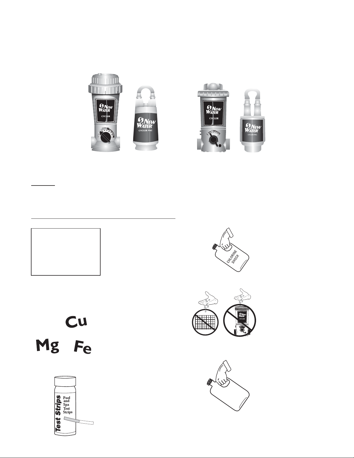
For In Ground Pools
®
For Above Ground Pools
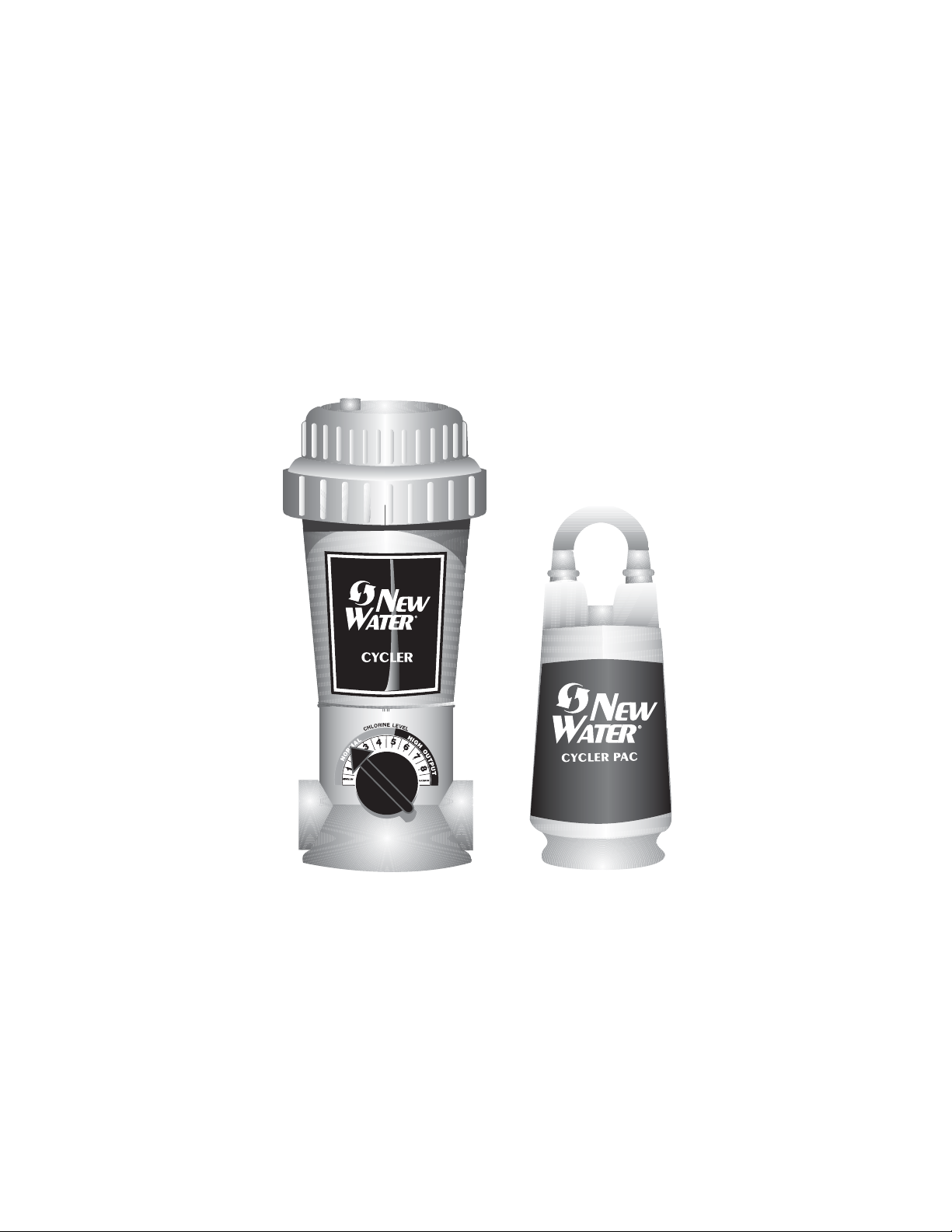
New Water® Cycler
The New Water Cycler is on constant watch dispensing chlorine to control bacteria and provide a protective bank of
sanitizer for your pool.
Pool Balancing
Water Balance Guidelines
Free Chlorine: 1.0 - 3.0 ppm
pH: 7.2 - 7.8
Total Alkalinity: 60 - 120 ppm
Calcium Hardness: 150 - 400
Total Dissolved Solids: <1500
Stabilizer: 20 - 80 ppm
3
1. Before beginning with
any pool care program,
you must first balance your
pool water. Take a water
sample to your local pool
professional or use a
complete test kit that will
test for the following
important elements.
2. If your fill water is high
in metals, use a
sequestering agent or
metal out at pool opening
only before inserting a
Pac. Follow manufacturer’s
directions.
3. After your pool is up
and running smoothly,
continue to test your water
for pH, total alkalinity and
chlorine and maintain its
balance by adding any
necessary adjustment
products (see your dealer
for details).
®
Stablizer
4. Shock the pool with
chlorine to rid water of all
contaminants before
beginning. Follow
manufacturer's directions
carefully.
5. Do not add shock in or
near the skimmer or into
the New Water Cycler as
it could damage
equipment, risk potential
explosion or discolor your
pool surface.
6. Add a stabilizer or
conditioner to the pool at
the beginning of the
season if the stabilizer
level is below 20 ppm. This
will prevent chlorine burn
off. Follow manufacturer's
directions carefully.
Page 4
New Water® Cycler
Installation
The New Water Cycler comes in several different models.
Please review this list, determine which model you have
and follow the appropriate installation instructions for that
model only.
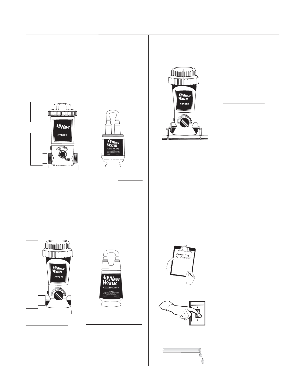
ABOVE GROUND POOLS
15 1/4"
1 1/2" i.d.
Cycler Model #100
In-line for above ground
pools ranging from 5,000
to 20,000 gallons. Uses a
5 lb. Cycler Pac. See
Pages 6 & 7.
Water
7 3/16"
®
5 LBS.
Replacement Cycler Pac
Model 105C for use in the
New Water Cycler Model
100.
IN GROUND – Off-line
®
Installation Tips
• Do not plumb into copper pipe as corrosion will occur.
• By installing a flow indicating device on the inlet line you
can monitor the gallons per minute.
See manufacturer’s directions for the installation of the flow
indicating device.
Cycler Model # 430
Off-line for in ground pools
ranging from 5,000 to 25,000
gallons. Uses a 7 lb. Cycler
Pac. See Pages 9 and 10.
IN GROUND POOLS
17"
2" I.D.
(Female
Threaded)
Cycler Model #400
In-line for in ground
pools ranging from 5,000
to 40,000 gallons. Uses
a 7 lb. Cycler Pac. See
Page 8.
®
7"
Before installing any of these Cyclers, make sure
that:
• You have all the supplies.
7 LBS.
• The pump is turned off.
Replacement Cycler Pac
Model 407C for use in the
New Water Cycler Models
400 and 430.
• The plumbing lines are dry.
4
Page 5
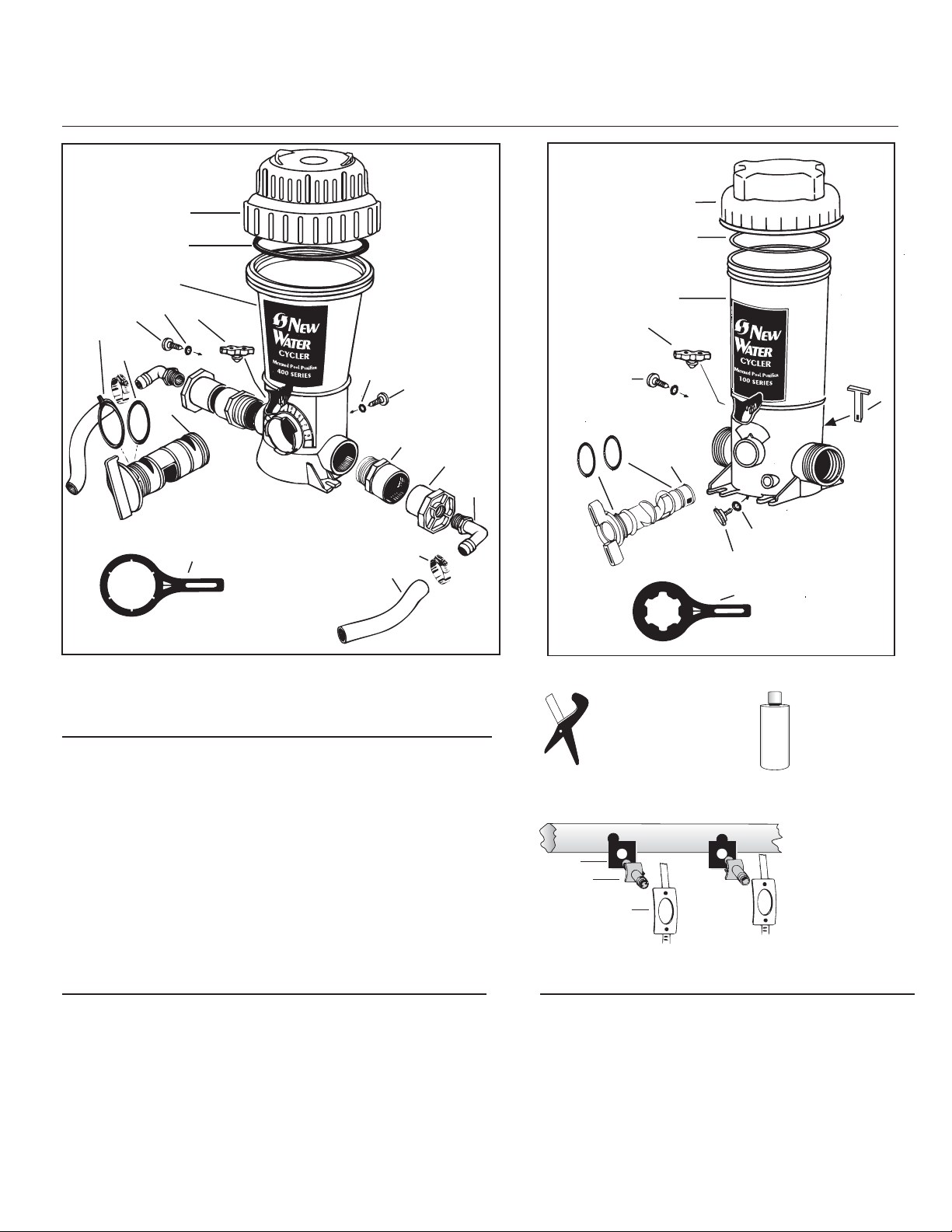
Parts List
Model 400/430
In ground
3
9
8
6
7
5
Model 100
1
Above
ground
2
4
9
8
10
11
4
8 & 9
6
12
18
13
14
1
2
3
7
5
9
8
18
CYCLER DIAGRAM/PARTS LIST • Model 400
REF. # PART No. DESCRIPTION QTY. REQ.
1 & 2 01-22-9412 Cap w/O-Ring 1
2 01-22-9920 Cap O-Ring 1
3 N/A Body 1
4 01-22-9480 Pressure Relief Valve 1
5, 6, 7 01-22-9441 Control Dial
with O-Rings 1
6 & 7 01-22-9450 Control Dial O-Ring Kit 1
8 & 9 01-22-9941 Knob with O-Ring 2
18 01-22-8870 Cap/Control Dial Tool 1
CYCLER DIAGRAM/PARTS LIST • Model 100
REF. # PART No. DESCRIPTION QTY. REQ.
1 & 2 01-22-1412 Cap w/O-Ring 1
2 01-22-1920 Cap O-Ring 1
3 N/A Body 1
4 01-22-9480 Pressure Relief Valve 1
5, 6, 7 01-22-1441 Control Dial
with O-Rings 1
6 01-22-1450 Control Dial O-Ring Set 1
7 N/A Control Dial Locking Pin 1
8 & 9 01-22-9941 Knob with O-Ring 2
18 01-22-9790 Cap/Control Dial Tool 1
5
REF. #: 19
O
?
T
H
Y
P
E
R
O
REF. #: 20
PART #: 01-22-9980
Cycler Pac Cutting Tool
QTY. REQ.: 1
C
S
I
E
L
I
N
C
O
L
U
T
B
N
R
A
I
C
C
O
Y
P
C
O
Y
P
C
O
P
Y
C
O
Y
P
PART #:
01-22-9970
Silicone
Lubricant
QTY. REQ.: 1
OFF-LINE
15
16
17
PARTS
Included with
Model 430
OFF-LINE PARTS Included with Model 430
REF. # PART No. DESCRIPTION QTY. REQ.
10 01-22-9490 2" Male Adaptor 2
11 01-22-8620 2" X 1/2" Bushing 2
12 01-22-7800 90 Degree Elbow 2
13 01-22-7690 Small Clamp 4
14 01-22-7700 6' PVC Tubing 2
15 01-22-7850 Scoop Gasket 2
16 01-22-7790 Venturi Scoop 2
17 01-22-7910 Scoop Clamp 2
19 01-22-9970 Silicone Lubricant 1
20 01-22-9980 Cycler Pac Cutting Tool 1
Page 6

TOOLS NEEDED
Above Ground, Base Installation – Model 100
Screwdriver
Wrench
MATERIALS NEEDED
Teflon Tape
Two Hose Adapters
1 1/2" X 1 1/2" X 1 1/4"
Two Sections of
of 1 1/2" Flex Hose
(one provided with filter)
Two
Hose
Clamps
PUMP
FILTER
Apply teflon tape to the
1.
threaded end of both hose
adapters.
TO POOL
Screw adapters into
2.
each end of Cycler.
Tighten turning 1 to
The Cycler should always be installed
between the filter and pool (or between
heater and pool if applicable).
2 revolutions with wrench.
DO NOT OVER TIGHTEN.
RECOMMENDED
Corrosion Resistant
Check Valve
#10 X 1 1/4" Phillips
Pan Head Screws with
Washers
OPTION
Half Union
or
1 1/2" Male Adapter
(slip x MPT)
When installing with
hard PVC pipe, use
either a half union on
the outside port
threads or a bushing
on the inside port
threads.
Attach the filter section of flex hose
3.
to one hose adapter and the return
section of flex hose to the other hose
adapter with clamps and tighten with
screwdriver.
HOSE
1 1/2" X 1 1/2" X 1 1/4"
CLAMP
HOSE ADAPTER
FILTER &
PUMP
1 1/2" OR 1 1/4"
FLEX HOSE
HOSE
ADAPTER
HOSE
CLAMP
HOSE
ADAPTER
HOSE
CLAMP
TO POOL
4
Isolating the Cycler by installing a corrosion resistant check
valve is recommended to protect the equipment and prevent
discoloration of pool surface.
5.
For better stability, Cycler may
be mounted on a base using
Phillips pan head screws.
6
Page 7

TOOLS NEEDED
Screwdriver
Wrench
MATERIALS NEEDED
Teflon Tape
One 6" X 1 1/2" TBE
PVC Nipple
One Hose Adapter
1 1/2" X 1 1/2" X 1 1/4"
Above Ground, Filter Installation - Model 100
2.
Screw one end of nipple
1.
Apply teflon tape to each
threaded end of nipple.
Apply teflon tape to
4.
threaded end of hose
adapter.
into the filter return.
Tighten turning
1 to 2 revolutions with wrench.
DO NOT OVER TIGHTEN.
Screw adapter into
5.
open end of Cycler.
Tighten turning
1 to 2 revolutions
with wrench. DO NOT
OVER TIGHTEN.
Screw either side of
3.
Cycler on to open nipple
end until upright and
secure.
One Section of
1 1/2" Flex Hose
(provided with filter)
One
Hose
Clamp
RECOMMENDED
Corrosion Resistant
Check Valve
6.
Attach return section of hose
to the adapter with clamp.
Tighten clamp with
screwdriver.
HOSE ADAPTER
7.
Installing a corrosion resistant
check valve is recommended.
7
Page 8

TOOLS NEEDED
Wrench
Hacksaw
In Ground, In-line Installation – Model 400
®
Do NOT install in copper pipe
Install after all equipment and as far as possible from heater.
as chemical corrosion occurs.
COPPER PIPE
MATERIALS NEEDED
Pipe Thread
Sealant
P
I
P
E
T
H
R
D
E
A
S
E
A
T
L
N
A
PVC
Cement
PVC
CEMENT
Two 2" Threaded
X 2" or 1 1/2" Slip
PVC Bushings
(not included)
RECOMMENDED
Corrision Resistant
Check Valve
#10 X 1 1/4" Phillips Pan
Head Screws with
Washers
®
®
Do NOT install an in-line
Cycler off-line as this Cycler
is different than an off-line unit.
Can be installed with the
water flow in either direction
due to its bi-flow control dial.
1. 2. 3.
P
I
P
E
T
H
R
D
E
A
S
E
T
A
N
L
P
I
P
W
M
a
t
e
r
C
Y
C
L
E
R
e
t
e
r
e
d
P
o
o
l
r
P
e
i
u
f
i
r
E
T
H
R
D
E
A
S
E
A
T
L
N
A
Following pipe thread sealant
directions, brush sealant onto
Cycler threads in both ports.
Brush sealant on the
threads of both male
adapters.
DO NOT USE TEFLON
TAPE as the threads
on these units
are not suitable
for this use and
leaking or fitting
failure could result.
A
®
12" to 15"
Leave 12" to
15" above
®
and around
Cycler to
allow room for
12" to 15"
easy
replacement
of Cycler Pac.
Screw a male adapter
into each port of
Cycler and hand tighten.
Completely tighten
turning 1 to 2
revolutions
with wrench.
DO NOT
OVER TIGHTEN.
Use Phillips pan head
screws through the
mounting holes at the
Cycler base to secure the
Cycler into a treated
wood base.
8
PVC
CEMENT
4.
Following PVC cement
directions brush PVC cement
on to ends of pipe and the
inside of male adapters.
5.
Insert PVC pipe into male
adapters. Hold in place
5 to 10 seconds to bond.
Isolating the Cycler by
6.
installing a corrosion
resistant check valve is
recommended to protect
the equipment and
prevent discoloration of
pool surface.
®
Page 9

TOOLS NEEDED
Wrench
In Ground, Off-line Installation – Model 430
Screwdriver
Battery
Operated Drill
with 5/8" or 19/32" Bit.
MATERIALS NEEDED
Pipe Thread
P
I
P
Sealant
E
T
H
R
D
E
A
S
E
A
T
L
A
N
PVC
Cement
PVC
CEMENT
OFF-LINE KIT
Included with Cycler
Two Male
Adapters
Two Reducer
Bushings
Two
90 Degree
Elbows
Four Hose
Clamps
6' of
Tubing
Two
Scoops
Two
Scoop
Gaskets
®
Do NOT install an off-line
Cycler in-line as this Cycler is
different than an in-line unit.
1.
P
I
P
T
H
R
E
S
E
A
L
A
Following pipe thread sealant
directions, brush sealant onto
Cycler threads in both ports.
Install off-line when
®
insufficient room for an inline
application. Install as far from
heater as possible.
Can be installed with the water flow in either direction due to
its bi-flow control dial.
2.
E
D
A
T
N
P
I
P
E
T
H
R
D
E
A
S
E
A
T
L
A
N
3.
Screw a male
Brush sealant on threads of
both male adapters.
adapter into each
port of Cycler and
hand tighten.
DO NOT USE TEFLON TAPE
as the threads on
these units are
not suitable for
this use and
leaking or bushing
failure could result.
Completely tighten
turning 1 to 2
revolutions
with a wrench.
DO NOT OVER
TIGHTEN.
®
Two Scoop Clamps
RECOMMEND
Corrosion Resistant
Check Valve
#10 X 1 1/4" Phillips Pan
Head Screws with
Washers
9
PVC
CEMENT
4.
Following PVC cement
directions, brush PVC cement
on reducer bushings and
inside of male adapters.
5.
Insert reducer bushing
into male adapter on both
sides. Hold in place 5 to 10
seconds to bond.
P
I
P
E
T
H
R
D
E
A
S
E
A
T
L
A
N
6.
Following pipe thread sealant
directions, brush sealant onto
elbow threads.
Page 10
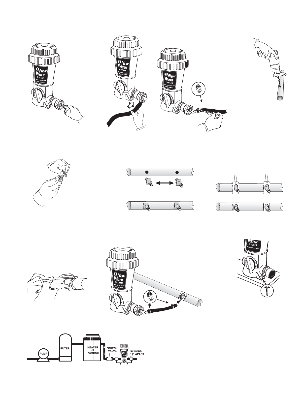
7. 8. 9. 10.
Screw elbow into reducer
bushings on both sides.
11.
Attach a gasket to
each scoop.
Cut tubing
to size for
each Cycler
connection
and attach
one to each
elbow with
clamps.
12.
Place scoops inside
holes so the inlet
scoop faces the
water flow and the
outlet scoop faces
away from the water
flow. Scoop arrows
should be facing
each other when
correct.
Tighten clamps
with a screwdriver.
Arrows on scoops must face each other.
When pipe is
totally dry,
drill two 19/32" or
5/8" holes
12" apart on the
return line. Be
careful not to go
through other
side of pipe.
13.
Attach scoop clamps
over the scoops and
around the pipe.
Tighten scoop clamps with
a screwdriver.
17.
10
15.14. 16.
®
Attach each hose to
venturi scoop male
nipple with a small
clamp and tighten with
screwdriver.
Isolating the Cycler by installing a corrosion resistant
check valve is recommended to protect the equipment
and prevent discoloration of pool surface.
For best results use Phillips
pan head screws through the
mounting holes at the Cycler
base to secure the Cycler into
a treated wood base.
Page 11

Replacing a Cycler Pac
CAUTION Read Carefully – USE ONLY the factory recommended replacement Pac. (See
label.) DO NOT USE any other Pac or bulk chemical tablets in the Cycler. Use of any other
product could result in over chlorination, bleached liners, unsafe pool conditions, fire or explosion.
Warranty will be void if the correct Pac is not used.
MIN.
1.
Turn off pump. Turn dial to
Minimum. This reduces the flow
of water into the unit when the
cap is open so isolation valves
MAX
2.
Use the cap tool included with Cycler to
loosen cap by hitting the handle with the flat
of your hand counter clockwise. Stand back
upon removing cap to avoid inhaling fumes.
are unnecessary.
Cutting handle from Cycler Pac using Pac Cutting Tool or a hacksaw
4.
Indent in plastic
A. Find the
indent in
the plastic.
B. If using a Pac Cutting Tool,
place curved section of tool
around the narrow end of one
Finished cut ends
Pac tower and line up blade on
indent.
Avoid a
pinched
opening.
(KEEP OUT OF REACH OF CHILDREN)
C. Squeeze the handles
together. Repeat for other
side.
3.
The Pac is made of HDPE
#2 plastic. When the Pac is
empty, triple rinse in pool
water, drain, and recycle or
wrap in newspaper and
discard in trash.
D. If using a hacksaw to cut
the Pac, line up hacksaw
blade on indent and cut with
a smooth sawing action.
E. Whether using a Pac
Cutting Tool or a hacksaw,
make sure the blade comes
straight across on the indent
line for a clean cut.
®
6.
®
11
F. If openings are pinched
together, open with fingers or
re-cut closer to the colored
screens inside Pac. Leave at
least 1/4" of plastic to fit into
Cycler base.
Insert Pac into Cycler,
lining up the openings in
Opening
in Pac
Key in
Cycler
Pac with keys in Cycler.
NOTE: Openings are a
different shape than keys.
Avoid sparks, open flame
or smoking when handling
the Pac.
A correct
oval opening
5.
Pac
towers
7.
New
®
Water
CYCLER
Metered Pool Purifier
400 SERIES
Replace cap by hand only.
DO NOT OVERTIGHTEN.
USE ONLY CYCLER PAC 400 SERIES
Turn Pac over and shake
slightly until tablets fall into
tower areas.
Pac
towers
DO NOT USE CAP TOOL
TO TIGHTEN CAP.
FOR REMOVAL ONLY.
Page 12

Setting Control Dial
POOL SIZE
Gallons Diameter
7,000 (18')
9,000 (21')
12,000 (24')
15,000
20,000
POOL SIZE
Gallons
7,000
9,000
12,000
18,000
25,000
30,000
12 Hour Pump Run Time 24 Hour Pump Run Time
1/2 hp 3/4 hp 1 hp 1 1/2 hp 1/2 hp 3/4 hp 1 hp 1 1/2 hp
2.5 2 1 3 1.5 1 1 2
3 2.5 2 3.5 2 1.5 1 2.5
3.5 3 2.5 2 2.5 2 1.5 3
4 3.5 3 2.5 3 2.5 2 1.5
4.5 4 3.5 3 3.5 3 2.5 2
3/4 hp 1 hp 1 1/2 hp 2 hp 3/4 hp 1 hp 1 1/2 hp 2 hp
2.5 2 3.5 3 1 3 2.5 2
3 2.5 2 3.5 2 3.5 3 2.5
3.5 3 2.5 2 2.5 2 1 3
4.5 3.5 3 2.5 3 2.5 2 1.5
NR
NR 4.5 3.5 3 3.5 3 2.5 2
NR
NR 5 4.5 3.5 NR 3.5 3 2.5
PUMP SIZE PUMP SIZE
*
*
*
*
*
12 Hour Pump Run Time 24 Hour Pump Run Time
PUMP SIZE PUMP SIZE
*
*
*
*
*
*
*
*
*
*
ABOVE
GROUND
POOLS
Approximate
Dial
Setting for
New Water
5 Lb. System
IN GROUND
POOLS
Approximate Dial
Setting for
New Water
7 Lb. System
Dial settings based on 1.5 ppm. * Bypass installation recommended. NR – This pump size is not recommended for this size pool.
1. Find your starting dial setting by matching up the
parameters of your pool on the above charts.
A 24 foot above ground pool with approximately 12,000
gallons and a 1 horse pump running 12 hours a day would
require a starting setting of 2.5. See example below.
If under chlorinating
CHLORINE
SHOCK
Increase the number of hours your
pump runs per day. If reading drops
below 1.0 ppm, shock pool again.
Turn control dial to minimum when
shocking and NEVER ADD SHOCK
IN OR NEAR THE SKIMMER. Reset
dial 1/2 setting higher than before and
ABOVE
GROUND
POOLS
POOL SIZE
Gallons Diameter
7,000 (18')
9,000 (21')
12,000 (24')
15,000
20,000
If over chlorinating
continue to monitor daily until desired
chlorine level is achieved.
Decrease the number of hours your
pump runs per day. Water must
circulate fully once a day. Remove
the Pac and place open ends down
l
o
P
o
a
n
d
S
a
p
T
t
s
e
s
p
S
i
t
r
Test Strips
2. For the first week or so, test
the water daily for free chlorine.
on the equipment pad until dry.
Avoid inhaling fumes. Avoid placing
on any surface that may be damaged
by chemical exposure. Keep out of
reach of children and pets.
12
3. After day one, adjust the dial up
by 1/2 increment if the free chlorine
reading has dropped or down by
1/2 increment if the reading has
risen. Continue this process each
day until the reading stabilizes at
your desired level between 1.0- 3.0
ppm.
Remember to adjust dial by
1/2 increments only. Higher than
suggested settings could result
in over chlorination and/or
bleached pool surfaces.
4. Use the handle end of cap tool if
the dial is hard to turn.
When reading drops to desired
ppm, replace Cycler Pac and ...
...decrease dial 1/2 increment.
Repeat this process until desired
chlorine level is maintained.
Page 13

For Ultimate Performance
1) Make sure back pressure Is between
3 and 8 psi
Higher back pressures result in over
chlorination. Lower back pressures result
in under chlorination. Adjust eye ball
fittings in the return jets to a larger size
to decrease back pressure or smaller
size to increase back pressure.
2) Determine possible high-flow
situations that require a special
installation such as:
A. Water flow is higher than 80 gpm.
B. In-floor cleaner is included with pool.
SUCTION
FROM
POOL/SPA
A. With High GPMS
Install T-fittings exactly as shown.
CHECK
VALVE
B. With In-floor Cleaners
CYCLER
TO POOL
C. Pool and spa combination with
common equipment.
NOTE: Over chlorination or damage to
the Cycler or other equipment could result
if these special installations are not used
in these situations.
3-WAY VALVE
CYCLER
➜
®
➜
➜
➜
➜
POOL WATER LEVEL
PUMP
➜➜
➜
➜
➜
➜
➜
➜
C. Pool and Spillover Spa Combination
SUCTION
CHECK VALVE
FROM
POOL/SPA
PUMP
IN-FLOOR
➜
➜
VALVE
➜
➜
➜
3-WAY
TO POOL
TO SPA
13
CYCLER
Page 14
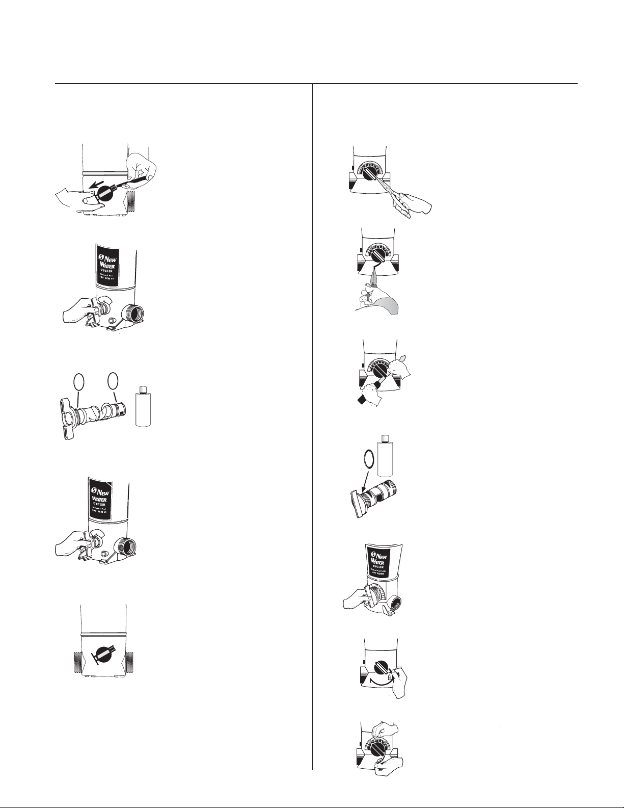
Cycler Maintenance
Replacing the Control Dial O-Rings for
Above Ground Cyclers
1. In the back of the Cycler
depress tab at end of locking
pin with a pen or screwdriver
and pull pin out of dial.
2. Turn control dial back and
forth as you pull it out of the
housing.
Back o-ring
3.
Replace both o-rings.
O
T
H
E
R
S
I
L
I
C
L
U
B
R
C
O
C
O
C
O
C
Please note: the back o-ring
?
Y
P
O
C
E
N
O
T
N
A
I
C
has a loose fit in the groove.
Y
P
Apply silicone lubricant that
Y
P
P
Y
O
Y
P
came with your Cycler on
o-rings.
Replacing the Control Dial O-Ring Kit for
In Ground Cyclers
1. Using a needle nose pliers,
find the snap ring tail located at
approximately the five o'clock
position under the control dial.
2. Pull down and out of the
groove.
3. Using a large screwdriver,
loosen the control dial. Carefully
pry the dial until it pulls out.
Carefully replace the rubber o-
O
?
T
Y
H
P
E
R
O
C
S
I
E
L
I
N
C
O
L
U
T
B
N
R
A
I
C
C
O
Y
P
C
O
Y
P
C
O
P
Y
C
O
Y
P
4.
ring without stretching it. Apply
silicone lubricant that came with
your Cycler on o-ring.
14
4. Carefully insert control
dial back into housing.
5. Replace locking pin by
pushing it through the slots
on the dial until it locks into
place.
5. Push control dial completely
into the housing and turn the dial
to setting 2.
6. Insert the non-lipped end of
snap ring into the groove opening
beginning at the 5 o'clock position
and push it up so that it threads
itself around the control dial.
7. Using a small screwdriver or
pointed tool to help guide it, make
sure the snap ring stays in the
groove as it is inserted.
Page 15

Replacing Cap O-rings
Winterizing
1. Hold cap in front of you
upside down with the o-ring
groove facing up. Place one end
of o-ring into cap groove at the
1. Turn dial to minimum. Turn
pump off . Unscrew side knob
of Model 100 to relieve
pressure.
point closest to you. Hold o-ring
down with the thumb and
forefinger of one hand.
2. Take hold of the far end of
2. Remove cap.
the o-ring with the thumb and
index finger of the other hand.
Roll o-ring slightly back towards
you as you stretch the o-ring into
the remainder of the cap groove.
N
e
w
W
a
t
e
r
3. Unscrew drain valve in
back of Cycler #400 or from
O
?
T
Y
H
P
E
O
R
C
S
I
E
L
I
N
C
O
L
U
T
B
N
R
A
I
C
3. Lubricate o-ring often with
silicone lubricant that came with
the front of Cycler #100. Allow
all water to drain.
your Cycler. DO NOT USE
C
Y
O
P
C
Y
O
P
C
O
Y
P
C
Y
O
P
petroleum based lubricants.
Replacing Knobs
• To replace, simply unscrew old knob
and replace with the new one.
• Front of 100 Cycler
• Side of 100 Cycler
• Back of 400 Cycler
4. Remove Pac.
5. Replace the cap and knobs
loosely.
®
6. If Pac still contains chlorine
wrap in plastic bag and store
in shed or garage away from
children and pets.
7. Make sure Pac is away
from open flame or anything
metal.
15
Page 16

Limited One-Year Warranty
King Technology, Inc. warrants to the original purchaser this unit
will be free from any defects in workmanship and/or material, for
a period of one (1) year from the date of original purchase. This
warranty covers body, cap and control dial, but specifically
excludes o-rings. King Technology at its option may replace any
defective parts or the entire unit without charge after it is
determined what is needed to correct any deficiency. Replacement
parts with the exception of o-rings are warranted for the remainder
of the original warranty.
1. To obtain warranty service, you must deliver the unit to King
Technology or its nearest authorized dealer. Shipping expenses
are the purchaser's responsibility. The name of the nearest
authorized dealer can be obtained by writing or calling King
Technology at the address and telephone number provided
below. Proof of purchase is required when requesting warranty
service. Purchaser must present the sales receipt or other
documentation verifying proof of purchase.
2. This warranty does not cover defects caused by: Modification,
alteration, repair or service of the unit contrary to the accompanying
instructions; physical abuse to or misuse of the product or
operation or installation in a manner contrary to the accompanying
instructions. This warranty also excludes all costs arising from
the installation, adjustment, removal or replacement of defective
units or parts. This warranty also excludes any and all claims
arising out of the chemicals used in the product or their
characteristics.
3. CAUTION - Read carefully – Failure to follow these
instructions will void the warranty. Do not add shock in or
near skimmer.
A. This unit is not designed for shock treatment of pools.
See your pool dealer or distributor for further information
concerning shock treatments.
B. Control dial settings in excess of the recommended setting
levels for trichlor can result in excess sanitizers being
discharged into the pool. This can result in bleaching or
discoloration of areas around the pool inlet or in some cases
bleaching or discoloration of the entire pool liner or paint.
C. Excess trichlor in the pool can create health hazards to
bathers. Consult each chemical manufacturer's warnings
and cautions for specifics.
D.
Misuse or failure to use the proper chlorine Pac for New
Water as directed in the instruction manual may cause
damage to equipment or personal injury. This warranty will
be null and void if this unit is not used with the recommended
chlorine Pac or Trichlor tablets.
4. This warranty is the exclusive warranty for the NEW WATER
Cycler. This warranty is not transferable. KING TECHNOLOGY
MAKES NO REPRESENTATION OR WARRANTY OF ANY
KIND, EXPRESS OR IMPLIED, AS TO MERCHANTABILITY,
FITNESS FOR A PARTICULAR PURPOSE OR ANY OTHER
MATTER CONCERNING THE NEW WATER
®
CYCLER. Any
express warranty not provided herein, and any remedy for breach
of contract but which for this provision might arise by implication
or operation of law is hereby excluded and disclaimed. THE
EXCLUSIVE REMEDY FOR ANY CUSTOMER IS THE REPAIR
OR REPLACEMENT OF THE UNIT, AND THE RECOVERY OF
DAMAGES WILL NOT EXCEED THE PURCHASE PRICE OF
THE UNIT. IN NO EVENT WILL KING TECHNOLOGY BE LIABLE
FOR ANY INCIDENTAL, CONSEQUENTIAL, SPECIAL OR
PUNITIVE DAMAGES FROM ANY CAUSE.
5. Under no circumstance shall King Technology be liable to
purchaser or any other person for any damage or loss incurred
because of any chemicals used in the product or their physical
characteristics, or interruption of service of the product, or any
resulting special, incidental or consequential damages or losses.
Some states do not allow the exclusion or limitation of incidental
consequential damages, so the above limitation or exclusion
may not apply to you.
®
U. S. Patent Numbers: 4,662,387; 5,076,315; 5,218,983
and other U.S. and Foreign Patents Pending
KING TECHNOLOGY, INC.
530 11th Avenue South, Hopkins, MN 55343 U.S.A. 952-933-6118 • 800-222-0169 • FAX 952-933-2206
www.kingtechnology.com
16
Made in U.S.A.
553100543R2
20-48-0149E
 Loading...