

Page 1

Bay Networks
Extranet Switch 2000
Getting Started Guide
Page 2

Bay Networks Part Number:
301461-B Rev. 00
Date:
April 1998
Accuracy Notice
The products and specifications, configurations, and other technical information regarding the
products contained in this docum en t are subject to change without notice. All stateme n t s, te ch n i c a l
information, and recommendati ons contained in this document are believed to be acc ur at e an d
reliable but are presented without warranty of any kind, expressed or implied, and users take full
responsibility for their application of any products specified in this document.
Copyright © 1998 Bay Networks, Inc.
All rights reserved. Printed in the USA. May 1998
The information in this document is subject to change without notice. The statements,
configurations, technical data, and recommendations in this document are believed to be accurate
and reliable, but are presented without express or implied warr an t y. User s must take fu ll
responsibility for their applications of any products specified in this document. The information in
this document is proprietary to Bay Networks, Inc.
The software described in this do cumen t is furn is he d u n der a lice nse ag reement and may only
be used in accordance with the terms of that license. A summary of the Software License is in
Appendix B.
Trademarks
Bay Networks is a registered trademark and Bay Networks 1000, Extranet Ready, the Extranet
Ready logo, Personal Extranets, Infrastructure for Extranets, and the Bay Networks logo are
trademarks of Bay N etwo rks, Inc.,
Microsoft, Windows 95, and Windows NT are registered trademarks of Microsoft Corporation.
The Microsoft Internet Explore r logo is a trademark or registered trademark of Micro s oft Corporation in
the United States and/or other countries.
This product conta ins RSA Sof tware.
This product incorporates MPPC
All other trademarks and registered trademarks are the property of their respective owners.
Restricted Rights Legend
Use, duplication, or disclosure by the United States Government is subject to restrictions as set
forth in subparagraph (c)(1)(ii) of the Rights in Technical Data and Computer Software clause
at DFARS 252.227-7013.
Notwithstanding any other license agreement that may pertain to, or accompany the delivery of,
this computer software, the rights of the United States Government regarding its use,
reproduction, and disclosu re are as set forth in the Commercial Computer Soft ware-Restricted
Rights clause at FAR 52.227-19.
ii
compression from Hi/fn.
Page 3

iii
Contents
................................
................................
...........
................................
................................
................................
....................
................................
................................
................................
...........
................................
................................
................................
.............
................................
................................
.................
................................
................................
................................
........................
................................
................................
................................
..............
................................
................................
...............
................................
................................
................................
........
................................
................................
................................
...................
................................
................................
................................
........
................................
................................
................................
..
................................
................................
................................
......................
................................
................................
................................
.....
................................
................................
.............
................................
................................
...........
................................
................................
............................
................................
................................
................................
...............
................................
................................
................................
.........
................................
................................
........................
................................
................................
................................
.........................
................................
................................
................................
...........................
................................
................................
..................
................................
................................
................................
..............
................................
................................
.......
................................
................................
......................
................................
................................
................................
...............
................................
................................
................................
....................
................................
...................
................................
................................
................................
..
................................
................................
................................
........
Preface.....................................................................................................v
Extranet Switch Documentation Map
Conventions
Documentation
User Interface
Bay Networks Customer Service
vi
vii
vii
vii
viii
Checking the Components.....................................................................1
Front View
Components List
Optional Sliding Rail Bracket Set
Cabling the Switch..................................................................................3
LAN Speed Selection
LAN Interface
Connector Pinouts
Optional WAN Interface
Serial Cable
Connecting the Cables
Understanding the Lights and LEDs
Assigning a System Identity...................................................................9
Startup Configuration Requirements
Management IP Address
Subnet Mask
Default Gateway
Private and Public Interfaces
Private
Public
IP Address Configuration Utility
Requirements
Running the IP Configuration Utility
Serial Interface Configuration
Prerequisites
Procedure
10
10
10
10
11
11
11
12
12
12
14
14
15
1
2
2
3
3
4
4
5
5
6
Managing the Switch.............................................................................17
Recommended Web Browser Versions and Settings
Platforms Supported
Browser Versions
Preface
17
17
17
Page 4

iv
Display Setting
................................
................................
................................
...........
................................
................................
................
................................
................................
..........................
................................
................................
................................
..................
................................
................................
................................
.
................................
................................
............................
................................
................................
................................
.................
................................
................................
................................
......................
................................
................................
..........
................................
................................
......
................................
................................
...............................
................................
................................
................................
...............
................................
................................
........................
................................
................................
................................
..................
................................
................................
................................
..
................................
................................
................................
.................
................................
................................
................................
..............
................................
................................
................................
.............
................................
................................
................................
..........
................................
................................
..............
................................
................................
................................
.................
................................
................................
................................
..........
................................
................................
................................
.....
................................
................................
..............................
................................
................................
................................
................................
................................
................................
..............
................................
................................
................................
.
................................
................................
........................
................................
................................
................................
..........
................................
................................
.............................
................................
................................
.............................
................................
................................
.....................
................................
................................
..................
................................
................................
................................
...........................
................................
................................
................................
.
Extranet Switch Welcome Display
Preparing for Configuration
Quick Start
Guided Configuration
Manage Extranet Switch
Registration
Notebook
Logging in and Supplying a Password
Quick Start Configuration Prerequisites
Required Environment
Prerequisites
Post-Configuration Testing
Configuration
LAN/WAN Interfaces
PPTP Users
Administrator
Date and Time
Automatic Backup
Extranet Access Client Installation
Windows 95
Windows NT 4.0
17
18
20
20
21
21
21
21
22
23
24
25
25
26
27
28
29
29
30
31
31
33
Rack Mounting...................................................................................... 35
Mounting Brackets
Sliding Rails (Optional)
36
38
Changing Hardware Configurations................................................... 41
Removing the Top Cover
System Board
Installing Option Cards
Installing Additional DIMMs
Memory Options
Replacing a Power Supply
Removing the Front Bezel
Removing the Hard Disk Drive
Replacing the Hard Disk Drive
41
43
44
45
46
47
48
50
51
Specifications....................................................................................... 52
Physical
Operating Environment
52
52
Special Notices..................................................................................... 53
Index...................................................................................................... 59
Preface
Page 5

v
Preface
This Getting Started Guide will step you through the necessary tasks to
get your Switch up and running fast. This guide provides information on
the following:
• Components
• Cabling, Lights, and LEDs
• Assigning a System Identity
• Accessing a Web Browser
• Managing the Switch
• Rack Mounting
• Changing Hardware Configurations
Complete details for configuring and monitoring the Switch are in the
Bay Networks Extranet Switch Administrator's Guide.
After attaching the Switch's cables, you can run the Bay Networks IP
Configuration utility on your PC to provide the Switch with IP configuration
information. Then you can begin to manage the Switch and view active
sessions. Instructions are also provided for installing the Switch into a
chassis rack, and installing additional LAN or WAN cards.
Preface
Page 6

vi
Extranet Switch Documentation Map
This map lists the associated documentation that you will need to configure
and manage your Bay Networks Extranet Switch and represents the order
that you would typically follow.
Bay Networks
Extranet Switch
1000/2000/4000
Getting Started Guides
Bay Networks
Extranet Switch
Release Notes
Bay Networks
Extranet Switch
Administrator's Guide
Gets you up and running
fast with a PPTP
connection
Provides latest information,
including known problems,
workarounds, and special
considerations
Provides details to
configure, monitor,
manage, and troubleshoot
your Switch
Preface
Page 7

vii
Conventions
bodily injury. Before working on equipment, beware
This guide refers to the Bay Networks Extranet Access Switch 2000 as the
Switch. This document assumes that you are familiar with Web browsers and
their general operation.
Documentation
This document uses the following conventions to distinguish among notes of
varying importance:
NOTE:
TIP
IMPORTANT:
Take notice. Notes contain helpful suggestions or references to
materials contained in this document.
: Good idea. A Tip is something that might be considered a good idea,
whether for security reasons or because it will save you time or effort.
User Interface
Take particular notice. Important references contain concepts or
information that has bearing on other fields or situations (i.e.,
what you do here affects other fields or options elsewhere).
CAUTION: Be careful. In this situation, you might do
something that could result in damage to the
equipment or loss of data.
WARNING: Danger. You are in a situation that could cause
of the hazards involved with electrical circuitry and
standard practices for preventing accidents, such as
disconnecting equipment from its power source.
Help Button
Click the Help button that is located in the upper right of displays to
learn about fields on a given page. Where appropriate, the information
provides cause and effect of an action; otherwise, it might offer
troubleshooting steps.
Preface
Page 8

viii
Bay Networks Customer Service
Contact the appropriate Technical Solutions Center below to get help on
your Switch.
Technical
Solutions Center
United States and
Canada
Valbonne, France 33-4-92-96-69-66 33-4-92-96-69-96
Sydney, Australia 61-2-9927-8800 61-2-9927-8899
Tokyo, Japan 81-3-5402-0180 81-3-5402-0173
Latin America 561-988-7661 561-988-7550
Telephone Number Fax Number
800-2LANWAN (800252-6926); enter
Express Routing
Code (ERC): 176#
978-916-3514
Preface
Page 9

Before you begin cabling and configuring the Bay Networks Extranet
Switch, examine the product packaging to be sure that you have all the
necessary components.
Front View
Following is a front view of the Switch.
Chapter 1
Checking the Components
Figure 1 − The Bay Networks Extranet Switch, Front View
1
Page 10

2
Components List
The following table lists all of the components and accessories of the Bay
Networks Extranet Switch 2000.
Description Quantity
Extranet Switch 2000
Power Cord (US and Canada only)
Molded Serial Cable DB9/DB25-to-DB9/DB25
Bay Networks Extranet Switch CD-ROM
Recovery Diskette
IP Address Configuration Utility Diskette
Administrator's Guide
Getting Started Guide
Extranet Switch Release Notes
Envelope with Product Literature
Mounting Brackets
Screws, #8-32 x 3/8 long, 100-degree flathead,
Phillips, black
1
Tinnerman rack mounting nuts #10-32
2
Screws #10-32 x 1/2 Truss PPH steel zinc
:
Notes
1
Used only if the rack is not threaded.
2
Used only with racks using 10-32 threading; some
racks use 10-24.
Optional Sliding Rail Bracket Set
Description Quantity
Slides
Slide Locking Brackets
Extender Brackets
Screws, #8-32 x 3/8 long, 100-degree flathead,
Phillips, black
Screws, #8-32 x 3/8 long, PPH steel zinc
If for any reason you have not received all of the materials listed above,
contact Bay Networks Customer Service (refer to page iii).
Checking the Components
Page 11

This chapter describes how to connect the cables that you must use with the
Switch, including pinouts for local area networks (LAN) connections, and how
to read the LEDs when the Switch is powered on.
LAN Speed Selection
The Switch automaticall y determines the speed of the LAN connection during
power-up. To change the speed simply power down the Switch, connect to the
desired LAN, and power the unit back up.
LAN Interface
100BASE-TX connections require Category 5, twisted-pair wire. The
100BASE-TX specification supports 100Mbps transmission over two pairs of
Category 5 twisted-pair Ethernet wiring; one pair each for transmit and
receive operations.
Chapter 2
Cabling the Switch
100 meters is the maximum recommended cable segment length
between a 100BASE-TX repeater and a workstation (due to signal
timing requirements). This wiring scheme complies with the EIA 568
wiring standard.
10BASE-T
connections can use Category 3, 4, or 5 twisted-pair wiring.
3
Page 12

4
Connector Pinouts
The LAN connectors on the Switch are RJ-45 straight-through. The
following illustration shows the Switch connector's 10/100BASE-TX
pinouts.
Figure 2 − 10/100BASE-TX Pinouts
Optional WAN Interface
The WAN connectors are located on a PCI card that is installed in the switch.
Two DB26S connectors provide the signals needed to interface to V.35
equipment. Included in the accessory box are two cables that map the DB26S
signals to a standard V.35 connector. The cable pin-outs are shown below.
DB26
Pin
1GNDA
2TDAP
3RDAR
4RTSC
5CTSD
6DSRE
7GNDB
8DCDF
9 RCB X
11 ETB W
12 TCB AA
14 TDB S
15 TCA Y
16 RDB T
17 RCA V
20 DTR H
24 ETA U
Figure 3 − DB26S-to-V.35 Cable Pinouts
Signal V.35
Pin
Cabling the Switch
Page 13

Note that you will need a DSU/CSU (digital service unit/channel service unit)
between the WAN connection and the Switch.
Serial Cable
The serial cable provided with the Switch is a DB9/DB25-to-DB9/DB25. This
provides a cross-over (transmit-to-receive and receive-to-transmit). The DB9
connector goes into the Switch and the other DB9 or DB25 connector goes
into your workstation or terminal. You should ignore the extra DB25
connection that is attached.
Connecting the Cables
1. Connect the 10/100BASE-TX LAN RJ-45 connector to the Switch.
2. Connect the power cord to the back of the Switch and to the electrical outlet.
3. Additionally, if you have LAN or WAN cards in Slots 1 through 3, connect
those cables (refer to Installing Optional Cards on page 44).
NOTE
: Slot 4 is not supported.
Slot1234
Power
Reset
Serial
Power Supply
LAN
Figure 4 − Extranet Switch Back View
Bay Networks ships a serial cable with the Switch. You can provide the Switch
with a Management IP Address, subnet mask, and default gateway address
via the Serial Interface (refer to page 14 for detai ls ). Bay Networks, however,
recommends that you use the IP Address Configuration Utility diskette for
easy initial IP address configuration (refer to page 12).
Cabling the Switch 5
Page 14

6
Understanding the Lights and LEDs
The Power light is green when the power is on; if it is flashing, there is a
hardware failure and you should contact Bay Networks.
The Reset light is green, and when it flashes the Switch is either reading or
writing to the disk. You can press the Reset button to restart the Switch,
however, Bay Networks recommends that you restart the Switch from the
System Shutdown display (refer to the Administrator's Guide for details).
Power on the Switch and confirm that the interfaces are cabled properly by
examining the two LEDs located adjacent to the RJ-45 connector of the LAN
port, or the LEDs located on the card panel.
Figure 5 shows the LAN Port LEDs and Figure 6 shows the PCI card
10/100BASE-TX LAN LEDs. Look at the condition of the LEDs, then examine
the corresponding LED tables to better understand the indications.
Figure 5 − LAN Port LEDs
LAN Port LED Indicators
LED Indicator Description
Orange
Green
(100)
On The cable connections between the LAN
port and the hub are good.
Off The cable connections between the LAN
port and the hub are faulty.
Flashing The LAN port is sending or receiving
network data. The frequency of the
flashes increases with increased traffic.
On The LAN port is operating at
100 Mbps.
Off The LAN port is operating at
10 Mbps.
Cabling the Switch
Page 15

Figure 6 − 10/100BASE-TX LAN LEDs
10/100BASE-TX LAN LED Card Indicators
LED Indicator Description
LNK
ACT
TX
On The cable connections between the card
and the device to which this interface is
attached are good.
Off The cable connections between the card
and the device to which this interface is
attached are faulty.
On or Flashing The card is sending or receiving
network data. The frequency of the
flashes increases with increased traffic.
Off The card is not sending or receiving
data.
On Operating at 100 Mbps.100
Off Operating at 10 Mbps.
Cabling the Switch 7
Page 16

Chapter 3
Assigning a System Identity
This section describes two methods, IP Address Co nfig uration Utility and
Serial Interface Configuration Procedure, that allow you to assign a
Management IP Address, subnet mask, and optional default gateway address
to your Extranet Switch. The Management IP Address is the address that is
used for all system services, such as HTTP, FTP, and SNMP. The Management
IP Address will enable you to manage the Switch from a Web browser.
Figure 7 shows the choices you have when first configuring your
Management IP Address, subnet mask, and default gateway. The IP
Address Configuration Utility is on a diskette that comes with your Switch.
Figure 7 − Initial Management IP Address Configuration
9
Page 17

10
Startup Configuration Requirements
This section provides descriptions of the fields that you must complete with
either the IP Address Configuration Utility or the Serial Interface
Configuration procedure.
Management IP Address
Enter a Management IP Address for the system. You need this address to
manage all system services, such as HTTP, FTP, and SNMP. This address
must be accessible from one of the Switch's private physical interfaces. In
order to do so, the Management IP Address must map to the same network
as one of the private interfaces.
For example, if you are planning on assigning IP address 10.2.3.3 with
the subnet mask 255.255.0.0 to the private physical interface, then the
Management IP Address must reside in the 10.2 network.
Carefully record the Management IP Address. Later, during the Quick
Start or the Guided Configuration, you will be asked to supply IP
addresses for the physical interfaces.
Subnet Mask
The Subnet Mask defines how many bits of the IP Address represent the
network the device is on and how many bits represent the host’s ID on
the network.
The device uses the Subn et Mask to determine which IP Addresses are
directly reachable on the network and which must be routed through a
gateway. A sample IP Address is 10.2.3.3 with a Subnet Mask of 255.255.0.0.
This indicates that all hosts with addresses 10.2.n.n are directly reachable.
Default Gateway
The Default Gateway is where packets are routed onto the private network if
there is not a specific rout e in the routing table to the desired location.
Assigning a System Identity
Page 18

11
Private and Public Interfaces
The Bay Networks Extranet Switch provides secure access between your local
area network (LAN) and Public Data Networks like the Internet. Throughout
this document the term Private refers to the LAN within your corporation,
and the term Public refers to Public Data Networks. This concept is
important because the Public interface accepts only tunneled protocols, while
the Private interface accepts both regular (nontunneled) and tunneled
protocols. You must be careful to correctly configure each interface of the
Switch for proper network security.
The LAN port is configured to be Private by default. Bay Networks
recommends that you connect this interface to your corporate LAN.
Additional interfaces that are inserted into the expansion slots are set to
Public by default.
Private
Indicates that this interface is attached to the internal corporate LAN and
accepts regular networking protocols such as TCP/IP, FTP, HTTP, etc. The
Private interface also accepts tunneled protocols (e.g., IPsec, PPTP, L2TP,
and L2F) that can be used for secure management access to the Switch.
Public
Indicates that this interface is attached to a Public Data Network like the
Internet. The Switch rejects nontunneled protocols and only accepts tunneled
protocols like IPsec, PPTP, L2TP, and L2F. For diagnostic purpos es, the
ability to PING the Public interface is also supported.
Assigning a System Identity
Page 19

12
IP Address Configuration Utility
Bay Networks provides a utility to perform the initial configuration of a Switch.
Requirements
To assign the Switch a Management IP Address with the Bay Networks IP
Address Configuration Utility you must have the following:
• A PC running Windows 95 or Windows NT with a functioning
TCP/IP stack.
• The PC must be running on the same subnet as the Switch that is
to be configured, and it must have an operational network
connection.
If your environment does not match these requirements, then you must use
the serial interface configuration.
To test the function of your TCP/IP stack, send a PING command to any host.
Running the IP Configuration Utility
The program "BayNetIP.exe" is on a diskette labeled "IP Address
Configuration Utility" that accompanies the Switch. You can copy the utility
to your hard disk and execute it from there, or you ca n load it from the
diskette drive. The "BayNetIP.exe" program launches the IP Address
Configuration Utility, which allows you to assign a Management IP Address
and subnet mask to the Switch. To run "BayNetIP.exe," follow these steps:
1. Insert the diskette into the A: drive and select Start→Run:
a:\BayNetIP.exe
or, open the "My Computer" icon on t he desktop and open the "3
Floppy (A:)" drive, then double-click on the icon:
Assigning a System Identity
ò
Page 20

13
The following display appears while the program searches for a Bay
Networks Switch that has not been configured with a Management IP
Address and subnet mask.
Figure 8 − Serial Number Search Display
2. The program automatically enters the Serial Number for the first
Switch discovered into the table of discovered Switches.
Figure 9 − IP Address Configuration Utility Display
3. Assign a Management IP Address and Subnet Mask to the Switch;
the Default Gateway address is optional and can be added later (refer
to Startup Configuration Requirements on page 10 for descriptions of
the required fields).
If you have more than one Switch, click Search to automatically add
the additional Switch serial numbers. To verify the Switches that
have been discovered, you can refer to the serial number on the bar
code on the back of the Switch.
Assigning a System Identity
Page 21

14
4. Click Apply to configure the Management IP Address, Subnet
Mask, and Default Gateway on the Switch. The IP Address
Configuration Utility display disappears.
When the Switch has completed updating its configuration with the
Management IP Address, Subnet Mask, and optional Default
Gateway, your default Web browser will automatically open to the
Bay Networks Extranet Switch Welcome display.
5. Click Close to shut down the IP Address Configuration Utility.
NOTE: Before moving the Switch from one network to another,
change the Management IP Address, subnet mask, and
default gateway. Otherwise, you will need to follow the Serial
Interface Configuration procedure to access your Switch
because it will not be accessible from a Web browser with an
invalid address.
Serial Interface Configuration
NOTE: Bay Networks recommends that you use the IP Address
Configuration Utility (refer to page 12) to provide the Switch with its
initial IP configuration information.
Alternatively, you can use this procedure to access the Switch via the Serial
Interface of your PC. Typically the Serial Interface configuration procedure is
only necessary in a system recovery situation. The Serial Interface allows you
to give the Switch a Management IP Address, Subnet Mask, and Gateway IP
Address so that you can use a Web browser for management.
Prerequisites
The terminal emulator on your PC must use the following
communications parameters:
• 9600 Baud
• 8 Data bits
• 1 Stop bit
• No Parity
• No Flow Control
Assigning a System Identity
Page 22

15
Procedure
1. Connect the serial cable from the Switch’s serial cable port to a terminal
or a communications port of a PC.
2. Using a terminal emulation program, such as Hyper Terminal, press the Enter
key and you are prompted to enter a user name and password. The factory
default user name and password are:
User name: admin
Password: setup
A menu appears that allows you to enter the following:
• Management IP Address
• Management IP Subnet Mask
• Gateway IP Address (optional)
• Allow HTTP Management (default)
• Controlled Crash
3. Follow the screen prompts. Descriptions of the fields required to complete this
procedure are in the section, Startup Configuration Requirements, on page 10.
Allow HTTP Management
A
Controlled Crash
creates a core dump file that Bay Networks Customer Support personnel
can analyze to help diagnose problems (e.g., the Switch is hung or it does
not respond to PINGs). Do not select "C) Controlled Crash" unless
instructed to do so by Bay Networks.
Assigning a System Identity
enables you to manage the Switch via a Web browser.
forces the Switch into a hard crash state, which
Page 23

16
A Sample display follows:
Welcome to the Bay Networks Extranet Switch
Copyright 1998, Bay Networks
Date: 4/29/98
Unit Serial Number: 01001
Please enter the administrator's username: admin
Please enter the administrator's password: setup
1) Management IP Address
2) Management IP Subnet Mask
3) Gateway IP Address
4) Allow HTTP Management
C) Controlled Crash
E) Exit
Please select a menu choice (1 – 4, C, E):
Figure 10 − Sample Serial Interface Display
4. Once you complete the configuration, type E to Exit. You can then manage
the Switch from a Web browser.
IMPORTANT: This Administrator's Password is also the Primary
Administrator's Password. This password guarantees
access to the Switch via the Serial Port or a Web browser.
Refer to page 29 for additional details.
Assigning a System Identity
Page 24

Chapter 4
Managing the Switch
This chapter describes the recommended Web browsers, the default login and
passwords to gain access to the Bay Networks Extranet Access Switch, and
the Quick Start Configuration.
Recommended Web Browser Versions and Settings
Bay Networks Extranet Manager uses Java, JavaScript, and HTML features.
For the management interface to function properly, verify that your Web
browser meets the following minimum requirements.
Platforms Supported
Windows 95, Windows NT, or Macintosh.
Browser Versions
Microsoft Internet Explorer − Version 3.01 or later (4.70.1215 or later).
NOTE: The Help→About box of Internet Explorer, Version 3.01 actually
displays: Version 3.00 (4.70.1215).
Not using a recent version of Internet Explorer causes the upper-left and topleft corners of the management displays to remain gray rather than displaying
the navigational menu and the current menu selection, respectively.
Netscape Communicator − Version 4.0 or later, and Netscape Navigator 3.x
or later.
Netscape Navigator Version 3.x Cache Settings − To ensure that you are
viewing the latest display information when using Netscape Navigator
Version 3.x, enable the "Every Time" option under the setting
Options→NetworkPreferences→Cache: Verify Documents.
Display Setting
Verify system display color setting is set to 256 colors or greater.
17
Page 25

18
Extranet Switch Welcome Display
The Welcome display allows you to enter any of the three configuration areas
for the Bay Networks Extranet Switch, including:
• Quick Start Configuration
• Guided Configuration
• Manage Extranet Switch
• Registration
• Notebook
Before entering the configuration opti ons, you should first register to act ivate
licenses, warranties, and services.
Figure 11 shows the alternatives you have when first configuring your
Switch. Bay Networks recommends that you begin with the Quick Start or
the Guided Configuration. Once you are familiar with the Switch's navigation
menu and capabilities, then you will want to select Manage Extranet Switch.
Figure 11 − Configuration Choices
Managing the Switch
Page 26

19
Figure 12 shows a sample Extranet Switch Welcome display. Descriptions of
each configuration option follow. A detailed checklist describes things you
will need to properly configure your Switch. Then full details of the different
procedures are described.
Complete details for configuring and monitoring the Switch are in the
Bay Networks Extranet Switch Administrator's Guide.
Figure 12 − Bay Networks Extranet Switch Welcome Display
Managing the Switch
Page 27

20
Preparing for Configuration
To properly prepare for Installation and Configuration of the Bay Networks
Extranet Switch, you should have the following items available:
A Management IP Address for the system. You need this address to
manage all system services, such as HTTP, FTP, and SNMP.
An IP Address for the LAN port that is available on the system board.
Any number of Public IP Addresses; e.g., one IP address for each
Public LAN Interface and one IP address for each T1 WAN interface.
A plan to distribute IP addresses to clients when connections are
requested; e.g., via a DHCP server or an internal client address
pool (with an address pool you will need a range of IP addresses).
An Authentication database: If you are not using internal
authentication via the LDAP database then make sure you have
either the external LDAP or the RADIUS server(s) IP Address and
password or shared secret.
An external accounting server, such as RADIUS, with its IP
Address and shared secret (password).
Client dial-in: Prepare the clients for the type of tunneling protocol
they will be using. The PPTP client application is available on the Bay
Networks CD for Windows 95, and it comes with Windows NT. Bay
Networks also provides the IPsec client on the Bay Networks CD.
A complete network topology of the "environment" in which you are
testing the Switch, including the Switch, the default router address,
and any other IP addresses that you think might be required.
Quick Start
Click to begin the Quick Start Configuration. This option allows you to
configure interfaces, set up PPTP tunnels for up to three users, and
establish a connection to the Switch. If you prepare for the configuration (as
recommended on page 24), the Quick Start can take as little as 15 minutes
to complete.
Managing the Switch
Page 28

21
Guided Configuration
Click to begin the Guided Configuration. This option allows access to all
Configuration Management facilities. However, the design and structure of
the Guided Configuration is best followed using the top-to-bottom layout
provided. This approach walks you through the entire Navigational Menu
from the Profiles to the Admin selections.
Each functional area begins with a summary of the objectives of the area and
then steps you through the area (e.g., Profiles), one subsection at a time.
On-line context sensitive help is available at each subsection to supplement
the summary.
Provided you have the information required to set up the Switch, the Guided
Configuration can to take two to three hours to complete, depending on how
extensive your configuration will be.
Manage Extranet Switch
Click to begin a standard configuration and management session. This option
allows access to all configuration management facilities. Bay Networks
recommends that you follow the Quick Start or Guided Configuration for your
first configuration.
Registration
Click to register the Switch with Bay Networks. It will only take a few
minutes and it will give you access to the latest software and technical tips.
Your Switch requires Internet access in order to register.
Notebook
Click to activate the notebook display mode. The Bay Networks Extranet
Switch Manager then runs in notebook display mode, which better fits
notebook displays.
Managing the Switch
Page 29

22
Logging in and Supplying a Password
Start up a Web browser and enter your Switch's Management IP
Address. Select an option in the navigational menu and submenu, and
then you are prompted for the Login and Password. Enter the system
default Login and Password in lowercase characters, as follows:
Login: admin
Password: setup
IMPORTANT
: If you change your password and later need to access the
Serial Interface Configuration, you must then enter the
modified password. The factory default password is no
longer valid in this case.
Also, make sure you change the default Administrator's
Login and Password as soon as possible (refer to the
Admin→Administrator display. You should then guard the
Login and Password carefully.
Managing the Switch
Page 30

23
Quick Start Configuration Prerequisites
This display acts as a checklist for you to prepare for the Quick Start
Configuration. Assembling the information beforehand, and verifying that
you can establish a PPTP Client session, makes the Quick Start easy.
Figure 13 − Quick Start Prerequisites Display
Managing the Switch
Page 31

24
Required Environment
This section describes the environment you must be using to perform the
Quick Start Configuration. If this does not describe your environment, use
the Guided Configuration.
Point-to-Point Tunnel Protocol (PPTP) tunnel access method
PPTP is a tunneling protocol supported by Bay Networks, Microsoft,
and other vendors. The PPTP client is available for Windows 95 on
the Bay Networks CD and comes with Windows NT 4.0 and later.
Static IP addresses, Dynamic Host Configuration Protocol
(DHCP) server address allocation, or an Internal Client
Address Pool
A DHCP Server on the private LAN segment dynamically assigns IP
addresses on behalf of remote users. The DHCP server is
automatically discovered via broadcasting on the private interface
that is associated with the Management IP Address. With an Internal
Client Address Pool you will need a range of IP addresses.
Local Lightweight Directory Access Protocol (LDAP) database
authentication
LDAP is a standard protocol for Internet directory services that is
based on directory entries. A directory service is a central repository of
user information. The local database is internal to the Switch.
An LDAP server and associated database will be set up locally on the
Switch for the Quick Start procedure. Later, you can switch to a
network-available external LDAP server using the LDAP
Intermediate File (LDIF) data format.
Managing the Switch
Page 32

25
Prerequisites
• IP configuration information (refer to Startup Configuration
Requirements on page 10 for additional information).
− A Management IP Address for the Switch
− Subnet Mask for the local subnet
• User IDs and Passwords
− PPTP Users (up to 3)
− Administrator
Post-Configuration Testing
• A PPTP remote user dialing in from an external system.
Refer to the Bay Networks Extranet Switch Administrator's Guide,
the Switch’s online help, and the Microsoft PPTP documentation for
additional information.
Managing the Switch
Page 33

26
Configuration
This display allows you to add a LAN port IP Address and Subnet Mask,
establish the tunnel as Private (your private LAN) or Public (public data
networks), and configure up to three PPTP Users and an Administrator
with User IDs and Passwords. Additionally, you can set the system’s Date
and Time.
Figure 14 − Quick Start Configuration Display
Managing the Switch
Page 34

27
LAN/WAN Interfaces
Interfaces
Lists the Management IP Address, LAN port, and any LAN or WAN cards
that you have installed in the Switch.
IP Address
Enter an IP address for each interface on the Switch, including the LAN port.
These IP addresses are used for tunnel creation. The IP Address consists of
32 bits, which are written as four octets in dotted-decimal format. For
example:
192.168.34.21
Note that the interface IP Address configuration information is required, not
the Management IP Address, which you already configured through the
initial IP Address configuration.
Subnet Mask
The Subnet Mask defines how many bits of the IP Address represent the
network the device is on and how many bits represent the host’s ID on
the network.
The device uses the Subn et Mask to determine which IP Addresses are
directly reachable on the network and which must be routed through a
gateway. A sample IP Address is 10.2.3.3 with a Subnet Mask of 255.255.0.0.
This indicates that all hosts with addresses 10.2.n.n are directly reachable.
Default Gateway
The Default Gateway is where packets are routed onto the private network if
there is not a specific rout e in the routing table to the desired location. Enter
a Default Gateway to LAN or WAN Interface cards, as necessary.
Managing the Switch
Page 35

28
Type
The default configuration for Switches assigns the Management LAN
interface as Private, and the LAN and WAN card interfaces as Public.
Public
Indicates that this interface is attached to a Public data network like the
Internet. The Switch rejects nontunneled protocols and only accepts
tunneled protocols like IPsec, PPTP, L2TP, and L2F and the diagnostic
protocol PING on a Public interface.
A host can send only enough packets to a Public interface to establish a
tunnel connection. If the tunnel is not established before the preset
maximum-number-of packets-allowed counter is reached, then the packets
from that host are discarded.
Private
Indicates that this interface is attached to the Private network and it can
accept nontunneled networking protocols such as TCP/IP, FTP, HTTP, etc. The
Private interface also accepts tunneled protocols (e.g., IPsec, PPTP, L2TP, and
L2F) that can be used for secure management access to the Switch.
PPTP Users
User ID
Enter a User ID. The User ID works along with the password as the
authentication mechanism when attempting to access your local LAN through
the Switch.
Password
Enter a user Password. You should use a minimum of eight characters,
including upper and lowercase letters and numbers. Avoid using common
names and words found in the dictionary. For example, a password
constructed as "AxSessPw4U" is much better than "dog" or "Barney."
: Do not use a password of 16 pound signs (#).
NOTE
Confirm Password
Reenter the assigned password to verify that you have typed the intended
password correctly.
Managing the Switch
Page 36

29
Remote User Static IP Address
Enter an IP Address to be assigned to this user when establishing a PPTP
tunnel session. Note that this IP Address is unnecessary if you assign user IP
addresses from either a DHCP server or an internal address pool.
Administrator
The Administrator Settings allow you to change the Primary Administrator
User ID (UID) and Password. The Primary Administrator User ID and
Password combination always has access to all displays and controls. This
UID is also used to access the serial port and the recovery disk.
Note that there can be only one Primary Administrator.
User ID
Enter an appropriate User ID for the Primary Administrator. This UID has
the privileges to modify and view all controls in the Switch.
Password
Enter a user Password for the Primary Administrator.
: Do not use a password of 16 pound signs (#).
NOTE
Confirm Password
Reenter the assigned password for the Primary Administrator to verify that
you have typed the intended password correctly.
Date and Time
Date
Enter the current month, day, and year (mm/dd/yy).
Time
Enter the current hour, minute, and seconds (hh:mm:ss) as displayed by a
24-hour clock (00:00:00 to 23:59:59).
Managing the Switch
Page 37

30
Automatic Backup
The Automatic Backup display under the Manage configuration option allows
you to configure regular intervals when your system files are saved to
designated host backup file serve rs.
IMPORTANT:
You configure the Automatic Backup servers from the Admin→Automatic
Backup display.
You should configure Automatic Backups immediately so that
you will not lose system or configuration information in case
of problems.
Managing the Switch
Page 38

31
Extranet Access Client Installation
Windows 95
To install the Bay Networks Extranet Access Client onto a Windows 95 PC,
you must first copy and install four files that are on the Bay Networks
Extranet CD in the Client folder. Interna tional software users should note
that you must go to the Microsoft web site
http://support.microsoft.com/support to get the MSDUN12 patch.
1. First, install Msdun12.exe (Microsoft Dial-up Networking update) by
double-clicking on the file name. The installation is self-explanatory.
You might need your Windows 95 CD (in case the CD was not copied
onto your drive). During the installation you will be asked to reboot
your system twice.
2. Next, install Wsockupd.exe (Winsock update) if you are using the
retail version of Windows 95. Reboot your system after installing the
update. You now have the Microsoft PPTP tunneling client installed.
3. Complete the IPsec installation by running the Eac_10d.exe, (Bay
Networks Extranet Access Client). The installation is selfexplanatory. You might need your Windows 95 CD-ROM (in case the
CD was not copied onto your drive). As prompted at the end of the
installation, reboot your system.
4. If you do not care about operating within the Network Neighborhood,
skip this step. To operate within the Network Neighborhood, enable
the following items under the Network Control Panel (click the Start
menu button, select Settings→Control Panel, then double-click on the
Network icon to open the Network Control Panel).
A. Under the box titled “The following network components are
Managing the Switch
installed,” verify that the Client for Microsoft Networks is
listed. If it is not, click on the ADD button, then select
CLIENT, then click the ADD button again. Select Microsoft
followed by Client for Microsoft Net works and finally the OK
button. You will need your Windows 95 CD if it is not already
copied on your system.
Page 39

32
B. Under the same box titled “The following network
components are installed,” make sure that NetBEUI is not
installed. To verify this, scroll down through the list box and
look for any lines that have NetBEUI in them. If there are
any lines that include NetBEUI, click on the line, and then
click on the Remove button. This forces the Network
Neighborhood to use NetBIOS over TCP/IP, which is
compatible with the Extranet Switch.
C. Under the Identity tab, configure the Workgroup to be the same
as your company's internal workgroup. For example,
"baynetworks."
D. Next under the Identity tab, verify that the Computer Name is
different from your PC at work. Otherwise, you would be
attempting to log a second unit with the same name onto the
network.
E. If you have made any changes in the Network Control Panel,
click OK, then reboot the system.
5. Double-click on the Extranet Connection Manager icon.
A. Enter a new Connection Profile Name.
B. Create a new Dial-up Connection.
C. Click the Tool button (next to the Dial-up Connection list box),
select New, and follow the wizard.
D. Create a new Extranet Connection.
E. Click the Tool button (next to the Extranet Connection list box),
select New IPsec Connection, and follow the wizard.
F. Click the Connect button.
Managing the Switch
Page 40

33
Windows NT 4.0
To install the Bay Networks Extranet Access Client onto a Windows NT 4.0
PC, you must first copy and install the Extranet Access Client (Eac_10d.exe)
that is on the Bay Networks Extranet Switch CD in the Client folder.
1. Install Eac_10d.exe by double-clicking on the program name. The
installation is self-explanatory. As prompted at the end of the
installation, reboot your system.
2. Install the Remote Access Service under the Network Control Panel
(click the Start menu button, select Settings→Control Panel, then
double-click on the Network icon t o open the Network Control Panel).
Select the Services tab and click on Add. Scroll down to select
“Remote Access Service” and click OK.
3. Under the Protocols tab, verify that NetBEUI is not installed. If
NetBEUI is listed, click on it, then click on the Remove button. This
will force the Network Neighborhood to use NetBIOS over TCP/IP,
which is compatible with the Switch. Click the OK button and reboot
your system.
4. Double-click on the Extranet Connection Manager icon.
A. Enter a new Connection Profile Name.
B. Create a new Dial-up Connection.
C. Click the Tool button (next to the Dial-up Connection list box),
D. Create a new Extranet Connection.
E. Click the Tool button (next to the Extranet Connection list box),
F. Click the Connect button.
Managing the Switch
select New, and follow the wizard.
select New IPsec Connection, and follow the wizard.
Page 41

Chapter 5
Rack Mounting
This chapter describes two methods you can use to mount your Switch into a
chassis rack.
• Rack-mount brackets for use with a two-post rack (page 36).
• Sliding rails for use with a four-post rack (optional purchase).
Following are standard rack-mounting considerations that Bay Networks
recommends you follow:
• The maximum recommended ambient temperature is 40 degrees
Centigrade. Additionally, make sure the internal temperature of the
rack does not exceed 40 degrees.
• Do not block the power supply vents or otherwise restrict airflow
when installing the Switch into a rack.
• Make sure that your rack is properly stabilized so that it will not tip
over under the weight of the Switch and other devices.
• Make sure that the electrical branch circuits are capable of handling
the Switch and other units in the rack before installing and
powering up the Switch.
• Ensure that a reliable Earthing path is maintained in the rack
system. The Switch is intended to be connected to an Earth ground.
35
Page 42

36
Mounting Brackets
g
g
The following illustration shows mounting brackets being attached to a
Switch in preparation of a two-post rack mount installation. Position the
brackets with the rack-mount bracket facing outward (as shown below).
Optionally, you can mount the brackets in the rear of a rack.
Mounting Rail
Rack Mountin
Front Mounting Bracket
Screws
Figure 15 − Bracket Installation for a Two-Post Chassis Rack Mount
Rack Mounting
Optional- Rear
Mountin
Bracket
Page 43

37
Rack Mount Installation Procedure
Bay Networks recommends that you have two people available when
installing the rack-mount brackets.
1. Position the bracket onto the Switch (as shown on the previous page),
then screw in the four rack-mounting screws. Repeat this step on the
other side of the chassis.
2. With one person holding the Switch in place, insert the two front
screws on each side to secure the Switch and brackets into the rack.
Rack Mounting
Page 44

38
Sliding Rails (Optional)
The following illustration shows the optional sliding rail assembly that
enables you to slide the Switch out of the rack and lift off the top cover for
interior access. Note that the sliding rail kit is optional and is separately
orderable.
: You must have a four-post rack to use the sliding rail mount assembly,
NOTE
and the rack must be at least 20-inches deep.
Optional extender brackets and hardware are provided in case your rack is
deeper than 20 inches. Attach the extender brackets to the sliding rails.
Bay Networks recommends that you have two people available when
installing the sliding rail assembly. The job is easier when one person holds
the rail brackets to the rack sides while the other person secures the
brackets to the rack. A second person is again necessary when sliding the
chassis into the rails.
Rack Mounting
Page 45

39
Rack Mountin
g
g
g
Bracket(s)
Mountin
Rail
Figure 16 − Sliding Rail Installation for a Four-Post Chassis Rack Mount
Rack Mountin
Screws
Rack Mounting
Page 46

40
Sliding Rail Installation Procedure
NOTES
These instructions are for sliding the chassis forward; reverse the closed-end
bracket for rearward travel.
:
• Insert all bracket mounting screws so that the screw heads are
inside the slides.
• Do not use washers on the inside of the slides.
• Mount the side brackets parallel to each other.
• Determine if the unit will slide to the front or rear of the rack.
1. Separate the slide rails from the rail bracket by pressing down on the
lock-release spring.
2. Mount the rail brackets to the inside of the rack, screwing an end
into each rail post. Do not tighten the screws until the chassis has
been installed.
3. Mount the sliding rails to the chassis. Note that the closed-end bracket
must be mounted at the front.
4. Mount the slide locking bracket to the top front left and right
sides of the chassis.
5. Pull out the bracket inner-rails so that the ball retainers are fully
forward. Install the chassis by positioning the slides into the slide rail
brackets and pushing the chassis into the rack.
6. Verify that the chassis slides correctly by pulling it forward and
pushing it closed. If it does not move smoothly, then the rails might
not be aligned properly; check the alignment.
7. Adjust the slide's positioning until the movement is smooth. Then,
tighten all screws.
8. Push the sliding rails in completely, then secure the rails by
inserting a screw into the slide prevention bracket.
Rack Mounting
Page 47

Chapter 6
Changing Hardware Configurations
This chapter describes how to change existing hardware
configurations, including:
• Installing LAN or WAN cards or adding memory.
• Swapping out a power supply.
NOTE: Wear an antistatic band when handling electronic components for the
Switch to avoid damaging them.
WARNING: Turn off the Switch and unplug it before installing
LAN or WAN cards, system memory, or installing
a new power supply.
To install LAN and WAN cards you must first remove the Switch's top cover.
To replace a power supply or to use the Recovery Diskette, you must remove
the front bezel of the Switch.
Removing the Top Cover
The following illustration shows you how to remove the top cover from the
Switch. You must remove the cover to:
• Install LAN or WAN cards.
• Install additional memory.
• Swap out a power supply.
41
Page 48

42
Remove the three screws
1
from top of cover
Lift rear of cover up,
2
and pull away from unit.
Figure 17 − Removing the Top Cover
1. Turn off the Switch's power and unplug it.
2. Remove the three screws at the top rea r of the chassis.
3. Slide the top cover back and move it away from the chassis.
Changing Hardware Configurations
Page 49

43
System Board
Figure 18 shows the Switch's System Board, in particular the DIMMs, Option Cards
Slots, Cooling Fans, and Replaceable Battery are noted.
Figure 18 − Switch's System Board
WARNING
Changing Hardware Configurations
: Beware of danger if the battery is incorrectly
replaced. Replace with the same or an equivalent
battery only, as recommended by the
manufacturer. Also, dispose of used batteries
according the manufacturer's instructions.
Page 50

44
Installing Option Cards
The following illustration shows you how install LAN or WAN option cards into the
Switch. You can use Slots 1 to 3 for any mix of LAN and WAN cards. Note that Slot 4
is not supported.
Figure 19 − Installing LAN or WAN Cards
1. Power off the Switch.
2. Remove the filler panel screw and pull out the filler panel.
3. Slide the option card into the intended slot. Make sure the card seats
firmly and evenly into the card slot. If the card is not seated properly,
it will not work.
Changing Hardware Configurations
Page 51

45
Installing Additional DIMMs
The following illustration shows you how to unlock a Dual Inline Memory
Module (DIMM), and remove or install a DIMM. Install DIMM in the next
available slot (i.e., if the DIMM # 1 slot is populated, then add the next
DIMM to the DIMM # 2 slot).
Figure 20 − Installing Additional Memory
1. Power off the Switch.
2. Press down the locking levers on both sides of the DIMM.
3. Pull the DIMM up to remove it from the slot.
4. Place a new DIMM in the slot, making sure to properly position t he
DIMM's alignment keys.
5. Pull up the locking levers on both sides of the DIMM, and snap in the
DIMM, as necessary.
Changing Hardware Configurations
Page 52

46
Memory Options
7280B6EDM4G11TK
The Switch ships with 64-MB memory installed. In case you want to
increase the memory, this table lists memory from different vendors that
has been tested with the Switch's System Board, and the vendor's
accompanying part number.
Vendor Part Number
2M x 72 (16Mb), Buffered ECC - 60ns
Micron Technology MT9LD272G-60X
Kingston Technology Corp. KTM2x72V82-60EG
PNY 722086EDM2G11TC
4M x 72 (32Mb), Buffered ECC - 60ns
Micron Technology MT18LD472G-60X
Samsung KMM372F400BK-6U
Kingston Technology Corp. KTM4x72V44-60EG
Southland Micro Systems SM572044A92E5G6
PNY 724056EDM4G20TC
8M x 72 (64Mb), Buffered ECC - 60ns
Advantage Memory Corp. AD872-4x4-60VE
IBM IBM11M8735CBD-60
Kingston Technology Corp.
Micron Technology
KTM8x72V84-60EG
MT9LD872G-6X
16M x 72 (128Mb), Buffered ECC - 60ns
Samsung KMM372F1600AK-6
Kingston Technology Corp. KTM16x72V44-60EG
Micron Technology MT36LD872G-6
PNY
Changing Hardware Configurations
Page 53

47
Replacing a Power Supply
Turn off the Switch before attempting to replace a Power Supply. Replacing a
power supply involves the following steps:
1. Remove the top cover (three screws).
2. Remove the four exterior screws that secure the Power Supply
to the rear of the Switch.
3. Detach the connectors from the following devi ces:
− Processor board
− Hard disk drive(s)
− Recovery diskette drive
4. Swap out the faulty power supply.
5. Reattach all cables and screws.
Changing Hardware Configurations
Page 54

48
Removing the Front Bezel
The following illustration shows you how to remove the front bezel from the
Switch. You must remove the bezel to insert the Recovery Diskette.
Slide fingers behind
front bezel and firm ly
pull forward in the
direction of arrows.
3.5-inch Disk Drive
Figure 21 − Front Bezel Removal
Changing Hardware Configurations
Front Bezel
Page 55

49
Note that the first few times you remove the front bezel it might seem to
resist removal. This is simply because the pins and snaps are new. After a
few times, removal is easier. Sliding the top cover back is optional; it allows
you to get a better grip on the front bezel for removal.
Remove the Switch front bezel as follows:
1. Optionally, remove the three screws at the top rear of the chassis,
then slide the top cover back.
2. Slide your fingers between the front bezel and the Switch.
3. Pull forward firmly.
Changing Hardware Configurations
Page 56
50
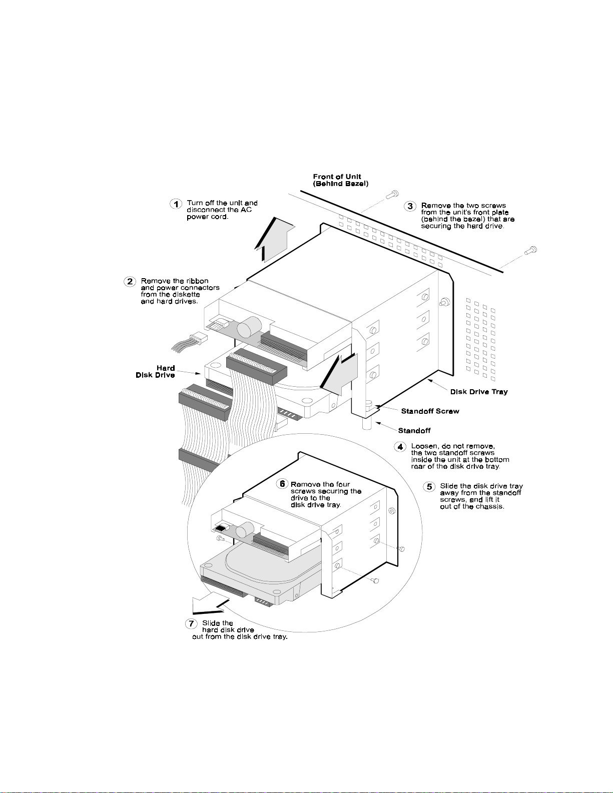
Removing the Hard Disk Drive
The following illustration describes how to remove a Hard Disk Drive from
the Switch.
Figure 22 − Removing the Hard Disk Drive
Changing Hardware Configurations
Page 57

51
Replacing the Hard Disk Drive
The following steps describe Replacing the Hard Disk Drive.
1. Reattach the four screws securing the drive to the disk drive tray.
2. Put the disk drive tray back inside the chassis and slide it back over
the two standoff screws.
3. Replace the two front screws, which draws the disk drive tray to the
front of the chassis.
4. Tighten the two standoff screws.
5. Attach the DC power cable at the bottom to the hard drive.
6. Attach the hard drive ribbon cable. Make sure the hard drive cable is
correctly positioned to the right.
: When standing in front of the unit, the red line on the ribbon
NOTE
cable that signifies Pin 1 is on the left (i.e., facing the center
of the unit).
7. Reattach the small ribbon cable to the diskette drive. Note that the
connector has a key at the center.
CAUTION
: Make sure the diskette drive connector gets replaced over
both rows; otherwise you would damage the drive.
Changing Hardware Configurations
Page 58

52
Physical
Depth: 17 in. (43.18 cm)
Width: 16.75 in. (42.55 cm)
Height: 7.00 in. (17.78 cm)
Weight: 25.0 lbs. (11.34 kg)
Electrical: 110-120/220-240V, 6.0/3.0A 50-60Hz
Operating Environment
Temperature: 32°F-122°F (0°C-50°C)
Appendix A
Specifications
Relative Humidity: 10%-90% non-condensing
Changing Hardware Configurations
Page 59

Appendix B
Special Notices
This appendix provides information on statements of conditions, the Bay Networks Software
License Agreement, and RADIUS attribution.
Statement of Conditions
In the interest of improving internal design, operational function, and/or reliability, Bay Networks, Inc.
reserves the right to make changes to the products described in this document without notice.
Bay Networks, Inc. does not assume any liability that may occur due to the use or application of the
product(s) or circuit layout(s) described herein.
Portions of the code in this software product may be Copyright © 1988, Regents of the University of
California. All rights reserved. Redistribution and use in source and binary forms of such portions are
permitted, provided that the above copyright notice and this paragraph are duplicated in all such forms
and that any documentation, advertising materials, and other materials related to such distribution and use
acknowledge that such portions of the software were developed by the University of California, Berkeley.
The name of the University may not be used to endorse or promote products derived from such portions
of the software without specific prior written permission.
SUCH PORTIONS OF THE SOFTWARE ARE PROVIDED “AS IS” AND WITHOUT ANY EXPRESS
OR IMPLIED WARRANTIES, INCLUDING, WITHOUT LIMITATION, THE IMPLIED
WARRANTIES OF MERCHANTABILITY AND FITNESS FOR A PARTICULAR PURPOSE.
In addition, the program and information contained herein are licensed only pursuant to a license
agreement that contains restrictions on use and disclosure (that may incorporate by reference certai n
limitations and notices imposed by third parties).
Federal Communications Commission (FCC) Compliance Notice: Radio Frequency Notice
Note: This equipment has been tested and found to comply with the limits for a Class A digital device,
pursuant to Part 15 of the FCC rules. These limits are designed to provide reasonable protection against
harmful interference when the equipment is operated in a commercial environment. This equipment
generates, uses, and can rad i ate radio frequency energy. If it is not installed and used in accordance with
the instruction manual, it may cause harmful interference to radio communications. Operation of this
equipment in a residential area is likely to cause harmful interference, in which case users will be required
to take whatever measures may be necessary to correct the interferen ce at their own expense.
EN 55 022 Statement
This is to certify that the Bay Networks is shielded against the generation of radio interference in
accordance with the application of Council Directive 89/336/EEC, Article 4a. Conformity is declared by
the application of EN 55 022 Class A (CISPR 22).
Warning: This is a Class A product. In a domestic environment, this product may cause radio
interference, in which case, the user may be required to take appropriate measures.
53
Page 60

54
EC Declaration of Conformity
This product conforms (or these products conform) to the provisions of Council Directive 89/336/EEC
and 73/23/EEC. The Declaration of Conformity is available on the Bay Networks World Wide Web site at
www.baynetworks.com.
Voluntary Control Council for Interference (VCCI) Statement
This is a Class A product based on the standard of the Voluntary Control Council for Interference by
Information Technology Equipment (VCCI). If this equipment is used in a domestic environment, radio
disturbance may arise. When such trouble occurs, th e user may be required to take corrective actions.
Canadian Department of Communications Radio Interference Regulations
This digital apparatus do es not exceed the Class A limits for radio-n ois e emi ssions from digital apparatus
as set out in the Radio Interference Regulations of the Canadian Department of Communications.
Règlement sur le brouillage radioélectrique du ministère des Communications
Cet appareil numérique respecte les limites de bruits radioélectriques visant les appareils numériques de
classe A prescrites dans le Règlement sur le brouillage radioélectrique du ministère des Communications
du Canada.
Special Notices
Page 61

55
Bay Networks, Inc. Software License Agreement
NOTICE: Please carefully read this l icense agreement before copying or using the accompanying
software or installing th e hard ware unit with pre-enabled software (each o f which is referred to as
“Software” in this Agreement). BY COPYING OR USING THE SOFTWARE, YOU ACCEPT ALL OF
THE TERMS AND CONDITIONS OF THIS LICENSE AGREEMENT. THE TERMS EXPRESSED IN
THIS AGREEMENT ARE THE ONLY TERMS UNDER WHICH BAY NETWORKS WILL PERMIT
YOU TO USE THE SOFTWARE. If you do not accept these terms and conditions, return the product,
unused and in the original shipping container, within 30 days of purchase to obtain a credit for the full
purchase price.
1. License Grant. Bay Networks, Inc. (“Bay Networks”) grants the end user of the Software (“Licensee”)
a personal, nonexclusive, nontransferable license: a) to use the Software either on a single computer or, if
applicable, on a single authorized device identified by host ID, for which it was originally acquired; b) to
copy the Software solely for backup purposes in support of authorized use of the Software; and c) to use
and copy the associated user manual solely in supp ort of authorized use of the Software by Licensee. This
license applies to the Software only and does not extend to Bay Networks Agent software or other Bay
Networks software products. Bay Networks Agent software or other Bay Networks software products are
licensed for use under the terms of th e applicable Bay Networks, Inc. So ftware License Agreement that
accompanies such software and upon payment by the end user of the applicabl e license fees for such
software.
2. Restrictions on use; reservation of rights. The Software and user manuals are protected under copyright
laws. Bay Networks and/or its licensors retain all title and ownership in both the Software and user manuals,
including any revisions made by Bay Networks or its licensors. The copyright notice must be reproduced
and included with any copy of any portion of the Software or user manuals. Licensee may not modify,
translate, decompile, disassemble, use for any competitive analysis, reverse engineer, distribute, or create
derivative works from the Software or user manuals or any copy, in whole or in part. Except as expressly
provided in this Agreement, Licensee may not co py or transfer the Software or user manuals, in whole or in
part. The Software and user manuals embody Bay Networks’ and its licensors’ confidential and proprietary
intellectual property. Licensee shall not sublicense, assign, or otherwise disclose to any third party the
Software, or any information about the operation, design, performance, or implementation of the Software
and user manuals that is confidential to Bay Networks and its licensors; howev er, Licensee may grant
permission to its consultants, subcontractors, and agents to use the Software at Licensee’s facility, provided
they have agreed to use the So ft ware only in accordance with the terms of this license.
Special Notices
Page 62

56
3. Limited warranty. Bay Networks warrants each item of Software, as delivered by Bay Network s and
properly installed and operated on Bay Networks hardware or other equipment it is originally licensed for,
to function substantially as described in its acco mpanying user manual duri ng its warranty period, which
begins on the date Software is first shipped to Licensee. If any item of Software fails to so function during
its warranty period, as the sole remedy Bay Networks will at its discretion provide a suitable fix, patch, or
workaround for the problem that may be included in a future Software release. Bay Networks further
warrants to Licensee that the media on which the Software is provided will be free from defects in
materials and workmanship under normal use for a period of 90 days from the date Software is first
shipped to Licensee. Bay Networks will replace defective media at no charge if it is returned to Bay
Networks during the warranty period along with proof of the date of shipment. This warranty does not
apply if the media has been damaged as a result of accid ent, misuse, or abuse. The Li censee assumes all
responsibility for selection of the Software to achieve Licensee’s intended results and for the installation,
use, and results obtained from the Software. Bay Networks does not warrant a) that the functions
contained in the software will meet the Licensee’s requirements, b) that the Software will operate in the
hardware or software combinat ions that the Licensee may select, c) that the operation of the Software will
be uninterrupted or error free, or d) that all defects in the operation of the Software will be corrected. Bay
Networks is not obligated to remedy any Software defect that cannot be reproduced with the latest
Software release. These warranties do not apply to the Software if it has been (i) altered, except by Bay
Networks or in accordance with its instructions; (ii) used in conjunction with another vendor’s product,
resulting in the defect; or (iii) damaged by improper environment, abuse, misuse, accident, or negligence.
THE FOREGOING WARRANTIES AND LIMITATIONS ARE EXCLUSIVE REMEDIES AND ARE
IN LIEU OF ALL OTHER WARRANTIES EXPRESS OR IMPLIED, INCLUDING WITHOUT
LIMITATION ANY WARRANTY OF MERCHANTABILITY OR FITNESS FOR A PARTICULAR
PURPOSE. Licensee is responsible for the security of its own data and information and for maintaining
adequate procedures apart from the Software to reconstruct lost or altered files, data, or programs.
4. Limitation of liability. IN NO EVENT WILL BAY NETWORKS OR ITS LICENSORS BE LIABLE
FOR ANY COST OF SUBSTITUTE PROCUREMENT; SPECIAL, INDIRECT, INCIDENTAL, OR
CONSEQUENTIAL DAMAGES; OR ANY DAMAGES RESULTING FROM INACCURATE OR
LOST DATA OR LOSS OF USE OR PROFITS ARISING OUT OF OR IN CONNECTION WITH THE
PERFORMANCE OF THE SOFTWARE, EVEN IF BAY NETWORKS HAS BEEN ADVISED OF
THE POSSIBILITY OF SUCH DAMAGES. IN NO EVENT SHALL THE LIABILITY OF BAY
NETWORKS RELATING TO THE SOFTWARE OR THIS AGREEMENT EXCEED THE PRICE
PAID TO BAY NETWORKS FOR THE SOFTWARE LICENSE.
5. Government Licensees. This provision applies to all Software and documentation acquired directly or
indirectly by or on behalf of the United States Government. The Software and documentation are
commercial products, licensed on the open market at market prices, and were developed entirely at private
expense and without the use of any U.S. Government funds. The license to the U.S. Government is
granted only with restricted rights, and use, duplication, or disclosure by the U.S. Government is subject
to the restrictions set forth in subparagraph (c)(1) of the Commercial Computer Software–– R estricted
Rights clause of FAR 52.227-19 and the limitations set out in this license for civilian agencies, and
subparagraph (c)(1)(ii) of the Rights in Technical Data and Computer Software clause of DFARS
252.227-7013, for agencies of the Department of Defense or their successors, whichever is applicable.
6. Use of Software in the European Community. This provision applies to all Software acquired for use
within the European Community. If Licensee uses the Software with in a country in the European
Community, the Software Directive enacted by the Council of European Communities Directive dated 14
May, 1991, will apply to the examination of the Software to facilitate interoperability. Licensee agrees to
notify Bay Networks of any such intended examination of the Software and may procure support and
assistance from Bay Networks.
7. Term and termination. This license is effective until terminated; however, all of the restrictions with
respect to Bay Networks’ copy rig ht in the Software and user manuals wi ll cease being effective at the date
of expiration of the Bay Networks copyright; those restrictions relating to use and disclosure of Bay
Networks’ confiden tial information shall con tinue in effect. Licensee may termi nate this license at any
time. The license will automatically terminate if Licensee fails to comply with any of the terms and
conditions of the license. Upon termination for any reason, Licensee will immediately destroy or return to
Special Notices
Page 63

57
Bay Networks the Software, user manuals, and all copies. Bay Networks is not liable to Licensee for
damages in any form solely by reason of the termination of this license.
8. Export and Re-export. Licensee agrees not to export, directly or indirectly, the Software or related
technical data or information without first obtaining any required export licenses or other governmental
approvals. Without limiting the foregoing, Licensee, on behalf of itself and its subsidiaries and affiliates,
agrees that it will not, without first obtaining all export licenses and approvals required by the U.S.
Government: (i) export, re-export, transfer, or divert any such Software or technical data, or any direct
product thereof, to any country to which such exports or re-exports are restricted or embargoed under
United States export control laws and regulations, or to any national or resident of such restricted or
embargoed countries; or (ii) provide the Software or related technical data or information to any military
end user or for any military end use, including the design, development, or production of any chemical,
nuclear, or biological weapons.
9. General. If any provision of this Agreement is held to be invalid or unenforceab le by a court of
competent jurisdiction, the remainder of the provisions of th is Agreement shall remain in full force and
effect. This Agreement will be governed by the laws of the state of California.
Should you have any questions concerning this Agreement, contact Bay Networks, Inc., 4401 Great
America Parkway, P. O. Box 58185, Santa Clar a, California 95054-8185.
LICENSEE ACKNOWLEDGES THAT LICENSEE HAS READ THIS AGREEMENT,
UNDERSTANDS IT, AND AGREES TO BE BOUND BY ITS TERMS AND CONDITIONS.
LICENSEE FURTHER AGREES THAT THIS AGREEMENT IS THE ENTIRE AND EXCLUSIVE
AGREEMENT BETWEEN BAY NETWORKS AND LICENSEE, WHICH SUPERSEDES ALL PRIOR
ORAL AND WRITTEN AGREEMENTS AND COMMUNICATIONS BETWEEN THE PARTIES
PERTAINING TO THE SUBJECT MATTER OF THIS AGREEMENT. NO DIFFERENT OR
ADDITIONAL TERMS WILL BE ENFORCEABLE AGAINST BAY NETWORKS UNLESS BAY
NETWORKS GIVES ITS EXPRESS WRITTEN CONSENT, INCLUDING AN EXPRESS WAIVER
OF THE TERMS OF THIS AGREEMENT.
Special Notices
Page 64

58
RADIUS (Remote Authentication Dial In User Service)
Livingston Enterprises, Inc.
6920 Koll Center Parkway
Pleasanton, CA 94566
Copyright 1992 Livingston Enterprises, Inc.
Permission to use, copy, modify, and distribute this software for any purpose and
without fee is hereby grant ed, provided that this copyright and permission notice
appear on all copies and supporting documentation, the name of Livingston
Enterprises, Inc. not be used in advertising o r publicity pertaining to distribution of
the program without specific prior permission, and notice be given in supporting
documentation that copying and distribution is by permission of Livingston
Enterprises, Inc.
Livingston Enterprises, Inc. makes no representations about the suitability of this
software for any purpose. It is provided "as is" without express or implied warranty.
[C] The Regents of the University of Michigan and Merit Network, Inc.
1992, 1993, 1994, 1995, 1996 All Rights Reserved
Permission to use, copy, modify, and distribute this software and its documentation for
any purpose and without fee is hereby granted, provided that the above copyright notice
and this permission notice appear in all copie s of the software and derivative works or
modified versions thereof, and that both the copyright notice and this permissi on and
disclaimer notice appear in supporting documentation.
THIS SOFTWARE IS PROVIDED "AS IS" WITHOUT WARRANTY OF ANY KIND,
EITHER EXPRESS OR IMPLIED, INCLUDING WITHOUT LIMITATION
WARRANTIES OF MERCHANTABILITY AND FITNESS FOR A PARTICULAR
PURPOSE. THE REGENTS OF THE UNIVERSITY OF MICHIGAN AND MERIT
NETWORK, INC. DO NOT WARRANT THAT THE FUNCTIONS CONTAINE D IN
THE SOFTWARE WILL MEET LICENSEE'S REQUIREMENTS OR THAT
OPERATION WILL BE UNINTERRUPTED OR ERROR FREE.
The Regents of the University of Michigan and Merit Network, Inc. shall not be lia ble
for any special, indirect, incidental or consequential damages with respect to any
claim by Licensee or any third party arising from use of the software.
Special Notices
Page 65

Index
1
10/100BASE-TX LAN
LEDs, 7
100BASE-TX
interface, 3
10BASE-T
interface, 3
A
additional memory
installing, 41
administrator, 25
administrator settings, 29
antistatic, 41
automatic backup, 30
B
Bay Networks
Customer Service, viii
Bay Networks Extranet Switch
Administrator's Guide
, 19
C
Category 3, 4
wiring requirements, 3
Category 5
wiring requirements, 3
caution, vii
components
list, 2
configuration choices, 18
connecting
cables, 5
conventions, vii
D
date, 29
DB26S to V.35
connector, 4
pinouts, 4
DB9 or DB25
connectors, 5
default gateway, 10, 27
DHCP, 24
dimensions of Switch, 51
DIMMs, 43
installing, 45
diskette
IP Address Configuration Utility, 12
documentation map, vi
DSU/CSU
required, 5
E
electrical, 51
F
front bezel
removing, 48, 49
G
gateway IP address
serial interface, 15
Guided Configuration, 18, 21
H
height, 51
I
initial configuration
options, 9
interface
IP address(es), 27
Internet Explorer
versions recommended, 17
IP address, 27
configuration utility, 13
IP Address Configuration Utility
diskette, 12
IP address(es), 25
IP Addresses, 10
59
Page 66

60
J
R
Java, 17
L
LAN cards, 27
installing, 41, 44
LDAP
, 24
LEDs
system board, 6
length, 51
login
default, 22
M
Manage Extranet Switch, 18, 21
memory
64-MB, 46
memory, increasing
vendors, 46
Microsoft Internet Explorer, 17
N
Netscape cache settings, 17
O
option card
slots, 5
option cards slots, 43
P
password
default, 22
power cords
connecting, 5
PPTP
, 24
private, 11
defined, 11
public, 11, 28
defined, 11
Q
Quick Start, 20
requirements, 23
rack mount, 36
installation procedure, 36
recovery diskette
drive, 48
registration, 18, 21
relative humidity, 51
RJ-45 pinouts, 4
S
safety, 41
power off, 44, 45
serial cable
connectors, 5
serial interface
configuration requirements, 14
connector, 5
serial number
search, 13
sliding rail
installation procedure, 40
sliding rails, 38
software, latest
registration, 21
speed
selection, 3
subnet mask, 25
Support
contacting Customer, viii
system board
illustration, 43
system board LAN, 27
system identity
assigning a, 9
system IP address
serial interface, 15
system IP subnet mask
serial interface, 15
T
technical tips
registration, 21
temperature, 51
terminal emulation
serial interface, 15
terminal emulator
communication requirements, 14
testing
a configuration, 25
Page 67

61
time, 29
top cover
removing, 41, 42
U
user ID, 28
user interface, vii
W
WAN cards, 27
installing, 41, 44
WAN connection
DSU/CSU, 5
warning, vii
Web browser, 14
Web browsers
recommended, 17
weight, 51
Welcome display, 18
width, 51
 Loading...