

Kingsman ZV3600N, ZV3600NE, ZV3600LP, ZV3600LPE, ZV4200N Installation Instructions Manual
...
Installation Instructions Installation Instructions
Model Numbers: ZV3600N, ZV3600NE, ZV3600LP, ZV3600LPE, Model Numbers: ZV3600N, ZV3600NE, ZV3600LP, ZV3600LPE,
ZV4200N, ZV4200NE, ZV4200LP, ZV4200LPE are ZV4200N, ZV4200NE, ZV4200LP, ZV4200LPE are
Certified to: ANSI Z21.50b-2009, CSA 2.22b-2009, CGA 2.17-M91 Certified to: ANSI Z21.50b-2009, CSA 2.22b-2009, CGA 2.17-M91
ZERO CLEARANCE VENTED GAS FIREPLACE ZERO CLEARANCE VENTED GAS FIREPLACE
INSTALLER: Leave this manual with the appliance.
CONSUMER: Retain this manual for future reference.
Read this complete manual before beginning installation.
These instructions must be kept with the unit for future reference.
FOR YOUR SAFETY
WARNING: If the information in these instructions is not followed exactly, a fire or explosion may
result causing property damage, personal injury or loss of life.
Warning: Improper installation, adjustment, alteration, service or maintenance can cause property
damage, personal injury or loss of life. Refer to this manual. Installation and service must be performed by
a qualified installer, service agency or the gas supplier.
Do not store or use gasoline or other flammable vapors and liquids in the vicinity of this or any other appliance.
What To Do If You Smell Gas
Do not try to light any appliance.
Extinguish any open flame.
Do not touch any electrical switch.
Do not use any phone in your building.
Immediately call your gas supplier from a neighbour's phone.
If you can not reach your gas supplier, call the fire department.
A Division of R-Co. Inc.
2340 Logan Avenue
Winnipeg, Manitoba, Canada R2R 2V3
Ph: (204) 632-1962
Printed in Canada Febru
y 21, 2013 Part # 36ZV-MAN
ar

2
Pre-installation Questions and Answers
About curing of the paint
Your stove or fireplace has been painted with the highest quality silicone stove paint. This paint dries quickly in 15-20
minutes when first applied at the factory. However, due to the high temperature silicone components, the paint will cure
when heat is applied to the appliance as it is first used. The following information applies to the curing process to get the
paint fully hard and durable.
Fire the appliance four successive times for 10 minutes each firing and a 5 minute cool down between each. Be aware
during log and firebox paint curing that a white deposit may be developing on the inside of the glass doors. It is important
to remove this white deposit from the glass doors using a commercial fireplace glass cleaner.
• Babies, small children, pregnant women and pets should leave the area during the cure phase.
• Ventilate well, open doors and windows.
• Do not touch during curing.
Why does my fireplace or stove give off odour?
It is normal for your fireplace to give off some odour. This is due to the curing of the paint, adhesives, silicones and any
undetected oil from the manufacturing process as well as the finishing materials used with the installations (e.g. marble,
tile and the adhesives used to adhere this product to the walls can react with heat and cause odours).
It is recommended that you burn your gas fireplace or stove for a minimum of four hours at a time with the fan off (if a fan
is present) after the curing of the paint has been completed. These odours can last upward to 40 hours of burn time; keep
burning at a minimum of four hours per use until odours dissipate.
Noise coming from the fireplace?
Noise is caused by the expansion and contraction of metal as the appliance heats up and cools down. This is normal and
is similar to the sounds produced by a furnace or heating duct. This noise does not affect the operation or longevity of
your fireplace.
Operating Instructions
1. Be sure to read and understand all the instructions in this manual before operation of appliance.
2. Ensure all wiring is correct and properly enclosed to prevent possible shock.
3. Check for gas leaks.
4. Make sure the glass door is properly installed before operation. Never operate the appliance with the glass door
removed.
5. Make sure venting and termination cap are installed and unobstructed.
6. If brick or porcelain liners are used, ensure they are installed.
7. Verify that the pilot can be seen when lighting the appliance. If not, the log or rock placement is incorrect.
8. If the unit is turned off, you must wait a minimum of 60 seconds before re-lighting it.
3
Table of Contents
Pre-installation Questions and Answers………………………………….............. 2
Operating Instructions………………………………………………………............. 2
Table of Contents……………………………………………………………............. 3
Warnings, Installations, and Operations………………………………….............. 4-5
Installation Requirements for the Commonwealth of Massachusetts…............. 5
Installation and Operation & Maintenance.......................................................... 6
Locating your Appliance..................................................................................... 7
Framing for your Gas Fireplace.......................................................................... 7-8
Clearance to Combustibles / Mantels................................................................. 9
Fan Installation.................................................................................................... 10
Installing Brick Panels......................................................................................... 11
General Glass Information.................................................................................. 12
Confirming Proper Venting of Appliance............................................................. 12
Log Assembly for Models ZV3600 and ZV4200................................................. 13
Log C42 Placement Guidelines.......................................................................... 14-15
Log C43 Placement Guidelines.......................................................................... 16-17
Log C44 Placement Guidelines.......................................................................... 18-20
Gas Line Installation........................................................................................... 21
Millivolt System, Lighting, and Burner Control.................................................... 22
Burner System Maintenance.............................................................................. 23
Conversion Kit Instructions – PART A................................................................ 23-24
Gas Conversion for Top Convertible Pilot (Series 019065X) – PART B............. 25
Gas Conversion for Modulator – PART C........................................................... 26
Spill Safety Switch.............................................................................................. 27
IPI Electronic Ignition System......................................................................... 28
Remote Control Operation.................................................................................. 29
IPI Electronic Ignition Parts List – Standard System.......................................... 30
IPI Configuration #1: Basic................................................................................. 31
IPI Configuration #2: Remote On / Off................................................................ 32
EGTM / GTM System -No Batteries.................................................................... 33
Configuration #3: Remote ON/OFF, Variable HI/LO, and Fan............................ 34
Electronic Ignition Lighting Instructions............................................................... 35
Vent Instructions................................................................................................. 36
Parts Lists........................................................................................................... 37-38
Trouble Shooting The Gas Control System........................................................ 39
-Glass Safety- All Units....................................................................................... 40
Limited Lifetime Warranty................................................................................... 41
Warnings, Installations and Operations
4
Installation Regulations
This gas appliance must be installed by a qualified installer in accordance with local building codes, or in the absence of local codes, with the current
CAN/CSA-B149.1 or .2 Installation Code (in Canada) or the current National Fuel Gas Code Z223.1-
This appliance, when installed, must be electrically connected and grounded in accordance with local codes, or in the absence of local codes, with the
current CSA C22.1 Canadian Electrical Code or with the National Electrical Code; ANSI/NFPA 70 when installed in the United States.
In the U.S.A
. Thermostats are not permitted for Vented Gas Fireplaces (ANSI Z21.50b-Decorative).
WARNING
FOR SAFE INSTALLATION AND OPERATION OF YOUR GAS FIREPLACE PLEASE NOTE THE FOLLOWING:
1. Do not clean when the glass is hot.
2. Do not use abrasive cleaners.
3. Using a substitute glass will void all product
warranties.
4. For safe operation, glass doors must be
closed.
5. When purging the gas line, the glass front
must be removed.
6. Do not strike or abuse glass. Take care to
avoid breakage.
7. Do not alter gas orifice.
8. No substitute materials may be used other
than factory supplied components.
9. This appliance gives off high temperatures and should be located out of heavy traffic areas and away from furniture and
draperies.
10. Children and adults should be alerted to the hazards of the high surface temperatures of this appliance and should stay
away to avoid burns or ignition of clothing.
11. Young children should be carefully supervised when they are in the same room as the appliance. Toddlers, young children
and others may be susceptible to accidental contact burns. A physical barrier is recommended if there are at risk individuals
in the house. To restrict access to a fireplace or stove, install an adjustable safety gate to keep toddlers, young children and
other at risk individuals out of the room and away from hot surfaces.
12. Under no circumstances should any solid fuels (wood, paper) be used in this appliance.
13. Under no circumstances should this appliance be modified. Any parts that have to be removed for servicing should be
replaced prior to operating this appliance.
14. Any safety screen or guard removed for servicing an appliance must be replaced prior to operating the appliance.
15. Installation and repair should be done by a qualified service person. The appliance should be inspected before use and at
least annually by a professional service person. More frequent cleaning may be required due to excessive lint from
carpeting, bedding material, et cetera. It is imperative that control compartments, burners and circulating air passageways of
the appliance be kept clean. Make sure that the gas valve and pilot light are turned off before you attempt to clean this unit.
16. Clothing or other flammable material should not be placed on or near the appliance. This appliance should not be used as a
drying rack for clothing nor should Christmas stockings or decorations be hung from it.
17. Do not use this heater if any part has been under water. Immediately call a qualified service technician to inspect the heater
and to replace any part of the control system and any gas control which has been under water.
18. Do not operate appliance unless completely installed as per installation instructions.
19. Failure to position the parts in accordance with these diagrams or failure to use only parts specifically approved with this
appliance may result in property damage or personal injury.
20. Do not operate appliance with the glass front removed, cracked or broken. Replacement of the glass should be done by a
licensed or qualified service person.
21. The front of the fireplace gives off high temperatures that could ignite combustible material which is kept close to the front of
the unit.
22. Ensure that power to the Fireplace is turned off before servicing.
23. Do not operate this Fireplace without the glass front or with a broken glass.
24. Improper installation, adjustment, alteration, service or maintenance can cause injury or property damage. Refer to the
owner’s information manual provided with this appliance. For assistance or additional information consult a qualified
installer, service agency, or the gas supplier.
25. Operation of this appliance when not connected to a properly installed and maintained venting system or tampering with the
blocked vent shutoff system can result in carbon monoxide (CO) poisoning and possible death.
26. This appliance is equipped with a three-prong (grounding) plug for your protection against shock hazard and should be
plugged directly into a properly grounded three-prong receptacle. Do not cut or remove the grounding prong from this plug.
WARNING
NFPA 54 when installed in the United States.
HOT GLASS WILL
CAUSE BURNS
DO NOT TOUCH GLASS
UNTIL COOLED.
NEVER ALLOW CHILDREN
TO TOUCH GLASS.
• Gas fired appliances may be used only for supplemental heat and/or decorative purposes and under no circumstances shall they
5
provide a primary heat source.
• This appliance must not be connected to a chimney flue serving a separate solid-fuel burning appliance.
NOTE: It is recommended that a Carbon Monoxide (CO) Detector be installed in or near bedrooms and on all levels of your home.
Place a detector about 15ft [4.5m] outside the room that houses your gas appliance.
Certified for installation in a bedroom or bed/sitting room. In Canada must be installed with listed millivolt thermostat.
In the U.S.A. Thermostats are not permitted for Vented Gas Fireplaces (ANSI Z21.50b-Decorative).
In USA see local codes.
Operations and Maintenance Instructions
For safe installation and operation note the following:
• Venting systems should be periodically examined by a qualified agency.
• The flow of combustion and ventilation air must not be obstructed.
• The Burner/Log Assembly has been engineered and permanently adjusted for proper flame control.
• Periodically remove the logs from the grate assembly and vacuum any loose particles from the grate and burner areas. See Log
Placement page to remove logs. Vacuum burner parts and replace logs.
• Never use your gas fireplace as a cooking device.
• Label all wires prior to disconnection when servicing controls. Wiring errors can cause improper and dangerous operation. Verify
proper operation after servicing.
Installation Requirements for the Commonwealth of
Massachusetts
In the Commonwealth of Massachusetts, the installer or service agent shall be a plumber or gas fitter licensed by the Commonwealth.
When installed in the Commonwealth of Massachusetts or where applicable codes; the unit shall be installed with a CO detector per the
requirements listed below.
1. For direct-vent appliances, mechanical-vent heating appliances or domestic hot water equipment, where the bottom of the vent
terminal and the air intake is installed below four feet above grade the following requirements must be satisfied:
A. If there is not one already present, on each floor level where there are bedroom(s), a carbon monoxide detector and alarm
shall be placed in the living area outside the bedroom(s). The carbon monoxide detector shall comply with NFPA 720.
B. A carbon monoxide detector shall be located in the room that houses the appliance or equipment and shall:
• Be powered by the same electrical circuit as the appliance or equipment such that only one service switch services
both the appliance and the carbon monoxide detector;
• Have battery back-up power;
• Meet ANSI./UL 2034 Standards and comply with NFPA 720; and
• Have been approved and listed by a Nationally Recognized Testing Laboratory as recognized under 527 CMR.
C. A Product-approved vent terminal must be used, and if applicable, a Product-approved air intake must be used.
Installation shall be in strict compliance with the manufacturer’s instructions. A copy of the installation instructions shall
remain with the appliance or equipment at the completion of the installation.
D. A metal or plastic identification plate shall be mounted at the exterior of the building, four feet directly above the location of
vent terminal. The plate shall be of sufficient size to be easily read from a distance of eight feet away, and read “Gas Vent
Directly Below”.
2. For direct-vent appliances, mechanical-vent heating appliances or domestic hot water equipment where the bottom of the vent
terminal and the air intake is installed above four feet above grade the following requirements must be satisfied:
A. If there is not one already present, on each floor level where there are bedroom(s), a carbon monoxide detector and alarm
shall be placed in the living area outside the bedroom(s). The carbon monoxide detector shall comply with NFPA 720.
B. A carbon monoxide detector shall:
• Be located in the room that houses the appliance or equipment;
• Be either hard-wired or battery powered or both; and
• Shall comply with NFPA 720.
A Product-approved vent terminal must be used, and if applicable, a Product-approved air intake must be used. Installation shall be in
strict compliance with the manufacturer instructions. A copy of the installation instructions shall remain with the appliance or equipment
at the completion of the installation.
For the state of Massachusetts a T-handle gas shut-off valve must be used on a gas appliance. This T-handle gas shut-off valve must be listed and
approved by the state of Massachusetts. This is in reference to the state of Massachusetts state code CMR238.
Installation and Operation & Maintenance
Installation Regulations
This gas appliance must be installed by a qualified installer in
accordance with local building codes, or in the absence of local
codes, with the current CAN/CGA-B149.1 or .2 Installation Code
(in Canada) or the current National Fuel Gas Code Z223.1 when
installed in the United States.
This appliance, when installed, must be electrically connected and
grounded in accordance with local codes, or in the absence of local
codes, with the current CSA C22.1 Canadian Electrical Code or
with the national Electrical Code; ANSI/NFPA 70-1987 when
installed in the United States.
The ZV3600 and ZV4200 model series is suitable for installation in
a bedroom or a bed/sitting room, when installed with a listed wall
thermostat.
FOR SAFE INSTALLATION AND OPERATION OF
YOUR GAS FIREPLACE PLEASE NOTE THE
FOLLOWING:
1. This appliance gives off high temperatures and should be
located out of heavy traffic areas and away from furniture
and draperies.
2. Children and adults should be alerted to the hazards of the
high surface temperatures of this appliance and should stay
away to avoid burns or ignition of clothing.
3. Children should be carefully supervised when they are in
the same room as your fireplace appliance.
4. Under no circumstances should this appliance be modified.
Any parts that have to be removed for servicing should be
replaced prior to operating this appliance.
5. Installation and repair should be done by a qualified service
person. The appliance should be inspected before use and
at least annually by a professional service person. More
frequent cleaning may be required due to excessive lint
from carpeting, bedding material, etcetera. It is imperative
that control compartments, burners and circulating air
passageways of the appliance be kept clean.
6. Control compartments, burners and air passages in this
appliance should be kept clean and free of dust and lint.
Make sure that the gas valve and pilot light are turned off
before you attempt to clean this unit.
7. The venting system (chimney) of this appliance should be
inspected at least once a year and if needed, your venting
system should be cleaned.
8. Keep the area around your appliance clear of combustible
materials, gasoline and other flammable vapors and liquids.
This appliance should not be used as a drying rack for
clothing nor should Christmas stockings or decorations be
hung from it.
9. Under no circumstances should any solid fuels (wood,
paper) be used in this appliance.
10. For safe operation, glass doors must be closed.
11. Do not use this heater if any part has been under water.
Immediately call a qualified service technician to inspect the
heater and to replace any part of the control system and any
gas control which has been under water.
12. WARNING: Do not operate appliance with the glass front
removed, cracked or broken. Replacement of glass should
be done by a licensed or qualified service person.
13. Do not operate appliance unless completely installed as per
installation instructions.
14.
Gas fired appliances may be used only for supplemental heat
and/or decorative purposes and under no circumstances shall
they provide a primary heat source.
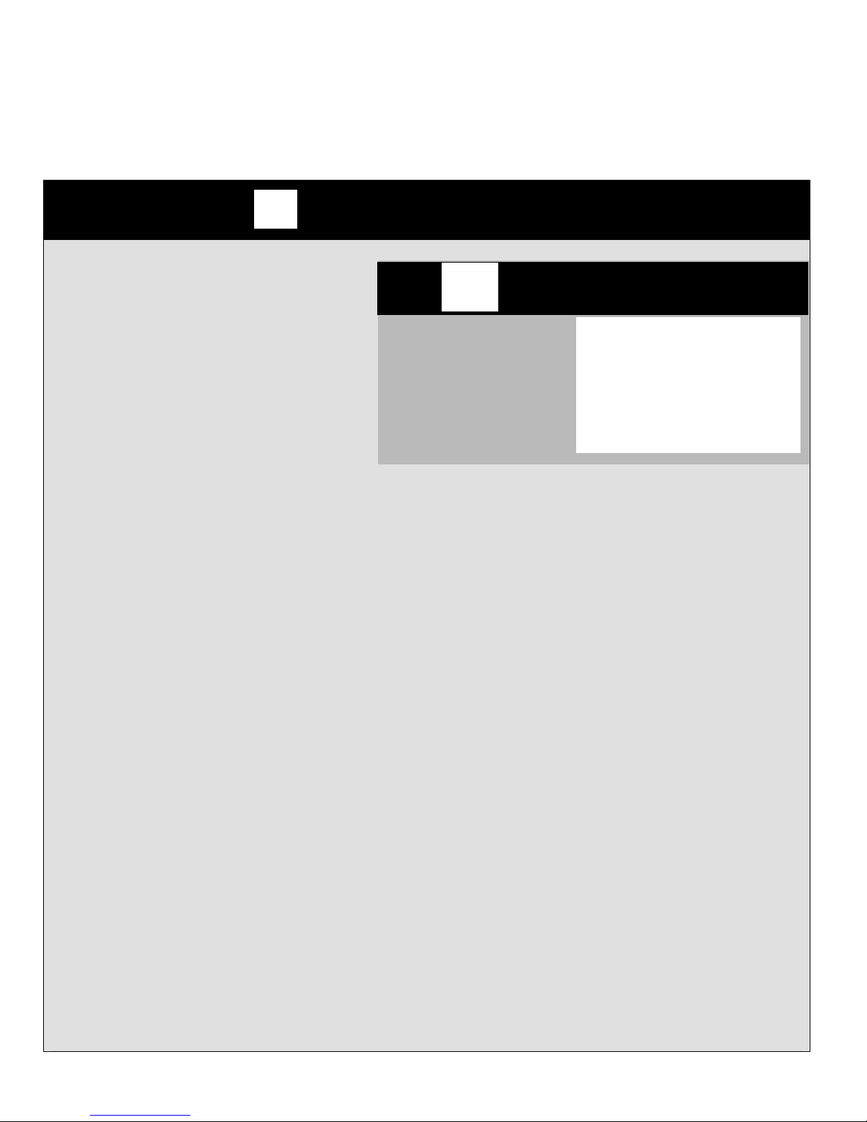
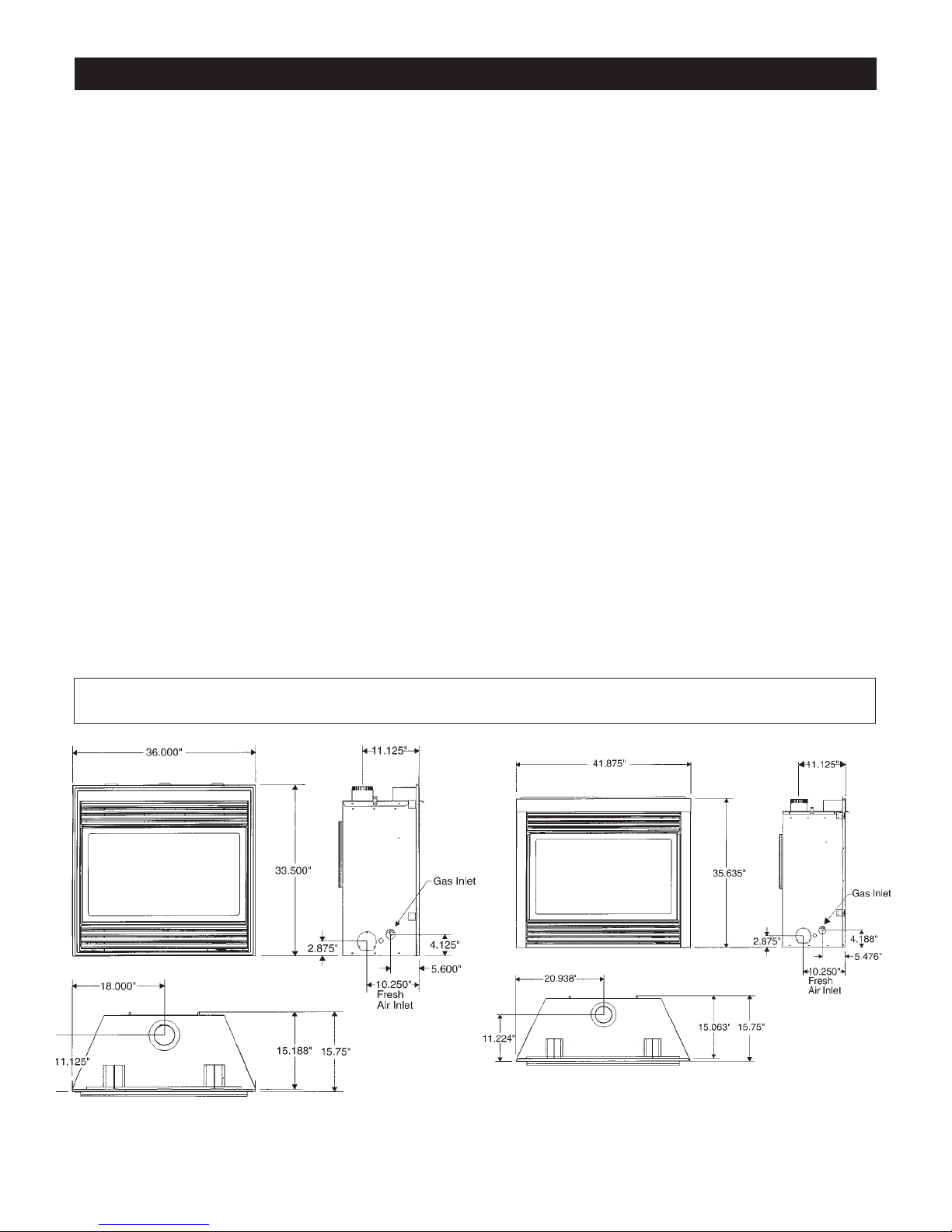
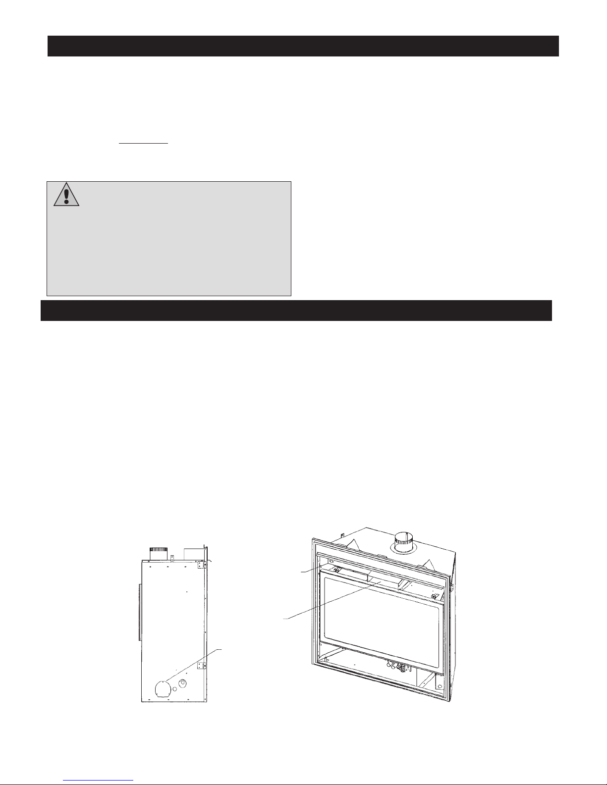
Dimensions for ZV3600
Dimensions for ZV4200
NOTE: It is recommended that a Carbon Monoxide (CO) Detector be installed in or near bedrooms and on all levels of your home. Place a
detector about 15 feet (4.5 meters) outside the room that houses your gas appliance.
6
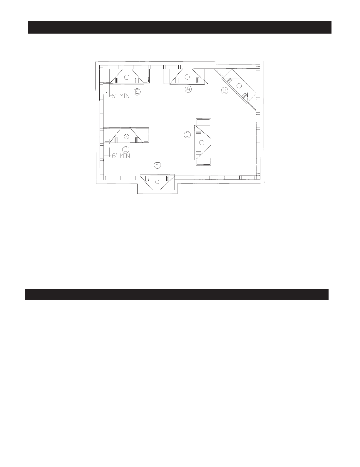
Locating your Appliance
(above or below grade)
Installing with Top Vent
When you install your fireplace as in position ‘B’, ‘D’ or ‘E’, a minimum
of 6 inches (153mm) clearance must be maintained from the perpendicular wall and the front of the appliance.
Framing Specifications
1. Cold climate installation recommendation: when installing this fireplace against non-insulated exterior wall or chase, it is recommended that the outer walls be insulated to conform to applicable insulation codes. Drywall should be installed over insulation to prevent
contact of insulation and unit.
2. Choose fireplace location and frame in accordance with the fireplace dimensions specified (See framing diagrams). Bend nailing tabs
forward on left and right of unit and place fireplace into framed enclosure. This allows for 1/2” in front of framing tabs for finishing
materials.
3. Drywall or other material can extend flush with the appliance on the bottom and sides of the fireplace.
4. Non-combustible materials such as brick and tile can be extended across the face of the fireplace. If wide brass trim kit is going to be
installed, brick and tile will have to be installed flush with the front of this appliance. If slim line brass trim kit is used, brick or tile may
extend past the front of unit.
Framing for your Gas Fireplace
A - Flat on a wall D - As a room divider
B - Across the corner E - Flat on wall corner
C - As an island F - Exterior wall
7
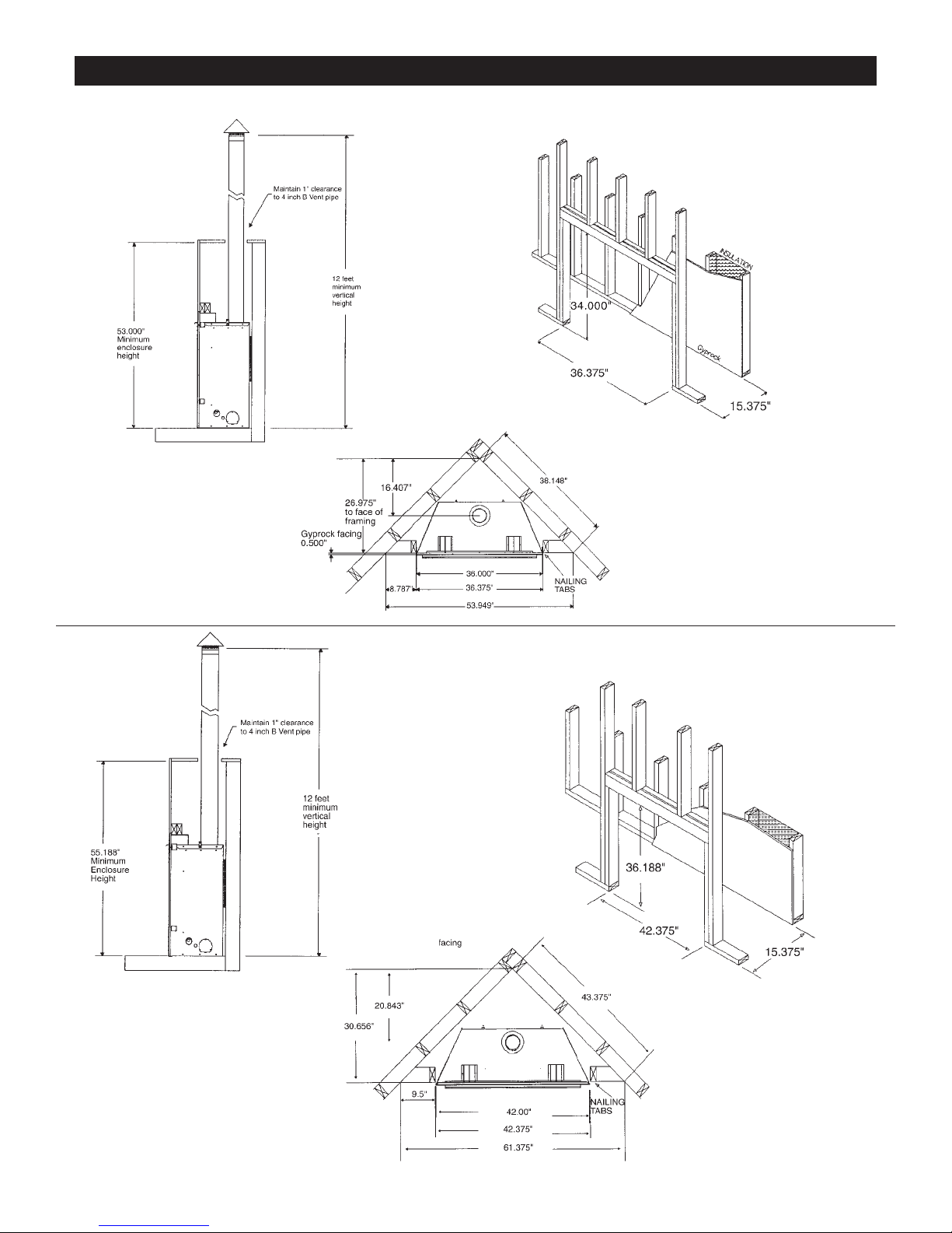
Framing for your Gas Fireplace (cont.)
FRAMING FOR ZV3600
FRAMING FOR ZV4200
4” B-Vent
4” B-Vent
8
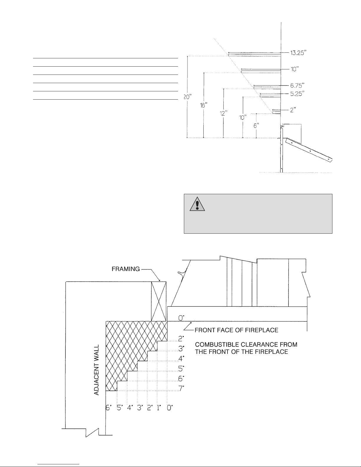
Warning:
Combustible objects must not be placed on
a non-combustible mantel unless the non-combustible mantel
meets the minimum height and width requirements for a
combustible mantel.
Clearance to Combustibles
Back (from Standoffs) 0 inches/0 mm
Side (from standoffs) 0 inches/0 mm
Floor 0 inches/0 mm
Top (from standoffs) 0 inches/0 mm
Top (from front of unit) 0 inches/0 mm
Note: See Mantel Chart
Hearth
A hearth is not mandatory but is recommended for aesthetic purposes. We recommend a non-combustible hearth projecting out
12” (305mm) or more in front of the fireplace.
9
Mantels
Depending on the width of the fireplace mantel, it may be
installed higher or lower from the top of the fireplace opening.
See drawings for proper installation height of your combustible
mantel. Non-combustible mantels may be installed at any height
above the fireplace opening.
Non combustible materials such as brick, tile, etc. can extend up
to or over the front face of the fireplace (NO PORTION OF
GRILL AREA OR DOOR AREAS CAN BE COVERED).
Combustible material can extend flush to unit up to the top, bottom and sides of fireplace to stand-offs.
If slim line brass surround is used, brick, tiles or other NONCOMBUSTIBLE materials may extend past the front of unit giving a recessed appearance. For COMBUSTIBLE materials
extending in front of fireplace consult “Mantel and Mantel Leg
Drawings”.
If wide brass surround is used finish materials must be flush with
front of unit.
Note: When using paint or lacquer to finish the mantel, such
paint or lacquer must be heat resistant (250˚F) to prevent
discoloration.
Installation of optional Fan Kit
#8x1/2”
FAN MOUNTING SCREWS
MOUNT FROM INSIDE OUTER RAP.
MOUNTING POSITION OF THERMO DISK
LOCATED LEFT SIDE AND BEHIND VALVE.
VARIABLE SPEED CONTROL
SUGGESTED LOCATION’
FOR 120V JUNCTION BOX
FOR FAN KIT.
120V
Fan Mounting Instructions: Z33FK-FAN ASSEMBLY
1. Attach thermodisk securely to bottom of firebox. Screws are factory installed.
2. Screw #8 x 1/2” screws into outer rap wall from the inside (right side only). Fan housing can
now be positioned by placing teardrop holes over the 2 screws mounted in the outer rap
wall.
3. Junction box should be mounted to opposite side and wired to variable speed control and
120V power.
4. Plug fan into junction box and attach the 2 leads exiting the fan housing into the thermodisk.
Electrical Services
All optional fan kits are equipped with a 120V, 60 Hz
blower.
Note: All electrical connections are to be made in
accordance with CSA Standard C22.1 - Canadian
Electrical Code part I or with the National Electrical
Code, ANSI/NFPA 70 (latest edition) and/or in accordance with local codes.
WARNING:
A
qualified electrician must
connect electrical wiring to
junction outlet for built-in
installation
WARNING:
Electrical Grounding Instructions.
This appliance is equipped with a three-pronged
(grounding) plug for your protection against shock
hazard and should be plugged directly into a properly
grounded three-prong receptacle. Do not cut or remove
the grounding prong from this plug.
WARNING:
Label all
wires prior to disconnection
when servicing controls.
Wiring errors can cause
improper and dangerous
operation.
Verify proper operation after
servicing.
10
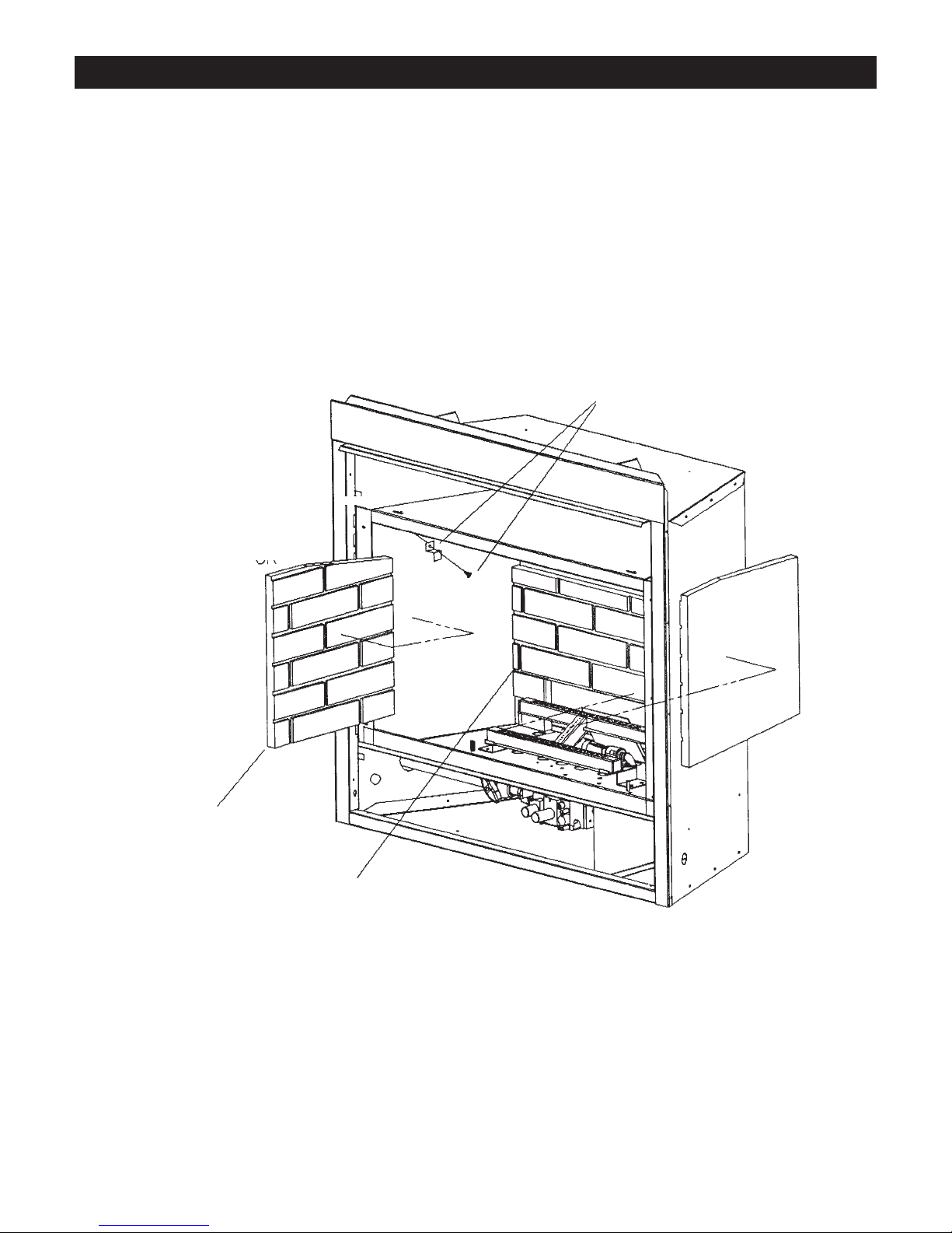
Installing Brick Panels
BRICK CLIP AND SCREW
LEFT AND RIGHT SIDE
REAR BRICK PANEL
LEFT SIDE
BRICK PANEL
1. Place rear brick panel up against the back of the firebox.
2. Loosen screw holding brick clip in position, swing clip up out of the way and place side brick
up to rear
brick and flush against side wall of firebox. Position clip over brick and tighten screw.
3. Repeat same procedure for opposite side brick panel.
11
General Glass Information
Glass Cleaning
It will be necessary to clean the glass periodically. During startup, condensation, which is normal, forms on the inside of the
glass and causes dust, lint etc. to cling to the glass surface.
Also, initial paint curing can deposit a slight film on the glass. It
is therefore recommended that initially the glass be cleaned two
or three times with non-abrasive
common household glass
cleansers and warm water. After that, the glass should be
cleaned two or three times a season depending on the circumstances.
Glass Replacement
REPLACEMENT GLASS FOR BOTH VENTED UNITS
Model Series ZV3600 or ZV4200 can use either tempered glass
or Robax ceramic or coated Neaoceram glass. Must be 5mm
thick.
To replace glass, clean all materials from door frame. Scrape off
old silicone down to metal. Using a high heat silicone (temperature-resistant to 500°F (260°C) apply a continuous bead of
approximately 1/32” to all four sides of frame and insert glass
with new gasket. Frame should be on flat surface, with a small
amount of weight pressing glass into silicone. Let dry approximately 15 to 20 minutes. The door can be re-installed by reversing Steps 1 & 2. Use caution when removing broken glass,
wear gloves.
Removal of the Glass Door
1. Remove the two screws located behind upper grill or unfasten
latches if so equipped.
2. To remove, pull frame forward and lift from bottom door retainer channel.
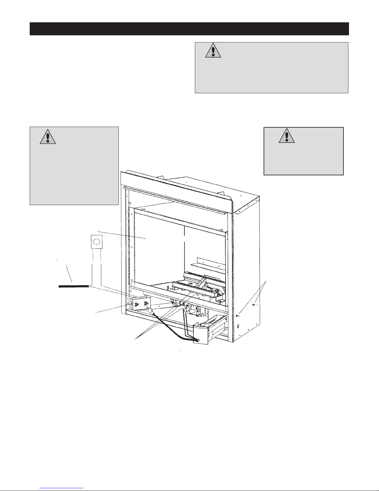
Confirming Proper Venting of Appliance
To check for proper drafting, use this procedure.
1. Place unit in operation and let run for approx.1 minute to establish up a draft.
2. Open top grill area to expose the draft hood.
3. Using a match or something that will produce smoke, place it up to the opening of the draft
hood and verify that the flame or smoke is being drawn into the draft hood. If the flame or
smoke is blown away from the draft hood opening, you may have to re-check the venting and
verify that there is a minimum of 12 foot of venting or check the house for negative pressure.
If there is negative pressure, you will have to bring fresh air to the unit.
left side only
safety spill switch
check draft here
Fresh air inlet
A Fresh Air Kit may be required by some building codes, remove cover plate on the bottom side of
unit and insert three inch flex duct into the side of fireplace by screwing it into the hole provided,
attach the other end to the plastic wall vent. When possible place the plastic vent below the bottom of the fireplace
Warning and Cautions.
• Do not clean when the glass is hot.
• Do not use abrasive cleaners.
• Using a substitute glass will void all product
warranties.
• Do not strike or abuse glass. Care must be
taken to avoid breakage of the glass.
• Do not operate this fireplace without the glass
front or with a broken glass.
12
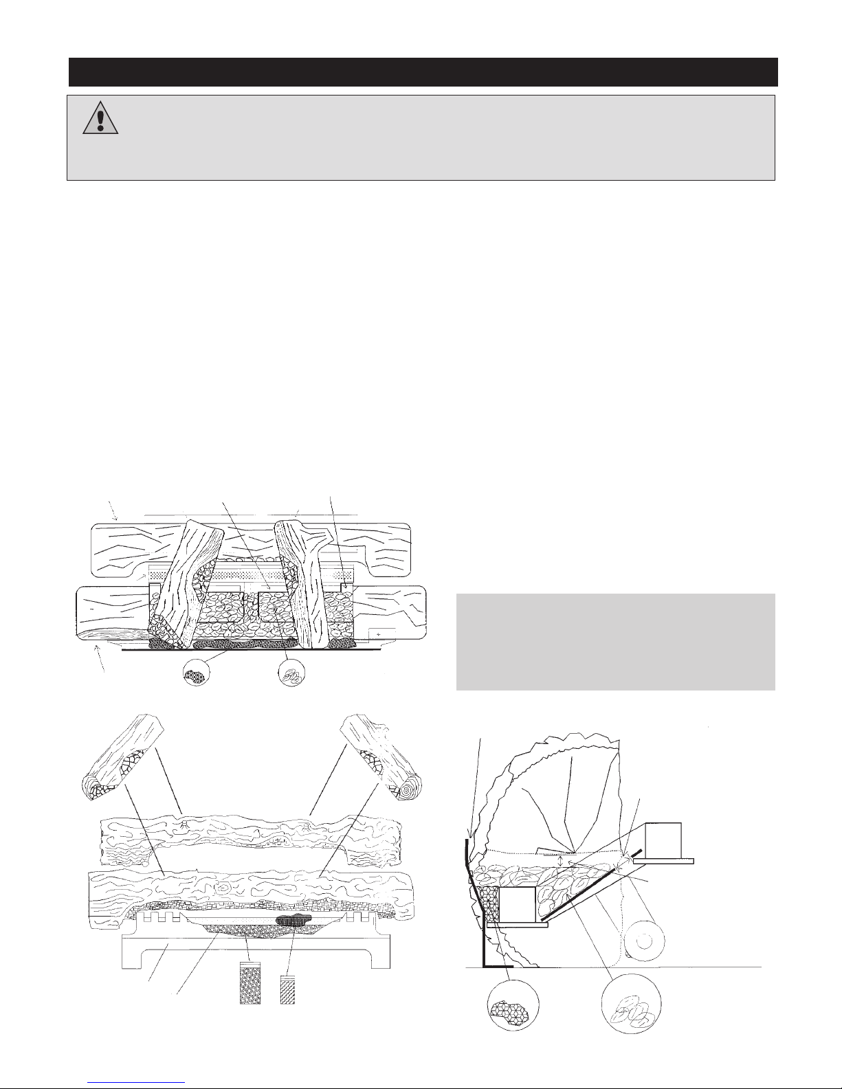
Log Assembly for Models ZV3600 and ZV4200
Log Assembly (LOGC42)
1.Remove glass door by removing two (2) screws behind upper
grills or unfasten latches and lifting door off bottom door
retainer channel.
2.Remove logs from carton (4 pcs) and inspect. (Part
#LOGC42)
3.Verify to see that ember plates (2 pcs) are between front and
back burner, air opening to top (as per diagram). The ember
plates are used to hold the glowing ember, thus simulating a
glowing bed of embers.
4.Place glowing embers (insulation) on surface of front burner
and surface of ember plates.
Height on front burner 1/2” - 3/4”
Height on ember plates 3/4” - 1”
Do not cover back air opening on ember plates.
5.Place rear log on log shelf 1/2” away from back of fireplace.
6.Place front log over front burner, and resting against decorative grate.
7.Place right and left logs across front and back log. Bark
should be to the outside, and right log has a knot.
8.Adjust right and left log so that black charred area sits
between front and rear log.
9.Make sure that a space of at least 3/4” is maintained
between glowing ember and underside of front log ember
bed area.
10.Front log should be centered on the log supports between the
front and rear burners. Pull log against the front of the supports.
11.Top logs can then be placed across the front and back logs in
the slots provided.
12.Place decorative moon rock on bottom of fireplace to simulate
ash and then sprinkle vermiculite over rock.
13.Purge lines and test pilot operation.
14.Replace glass door. The door must be installed before operating the fireplace.
REAR LOG
LEFT LOG
RIGHT LOG
EMBER PLATE
FRONT LOG
LEFT CROSSOVER LOG
Part # 4200-253
REAR LOG
Part # 4200-252
FRONT LOG
Part # 4200-251
FRONT GRATE
FRONT BURNER
ROCK MINERAL WOOL
LOG SET 4200-250
RIGHT CROSSOVER LOG
Part # 4200-254
BURNER
MOON ROCK
GLOWING
EMBERS
! EMBER PLATE AIR OPENING.
! DO NOT COVER UP !
! LOG MUST BE BROUGHT UP TO
FACE OF FENCE !
! EMBER PLATE AIR OPENING.
MUST NOT BE COVERED !
!OPENING BETWEEN
GLOWING EMBERS AND
UNDERSIDE OF LOG. MUST
NOT BE LESS THAN
3/4 INCH !
MOON ROCK
GLOWING
EMBERS
DO NOT PLACE DECORATIVE
ROCK ON BURNERS
WARNING:
Failure to position the parts in accordance with these diagrams or failure to use only parts specifically
approved with this appliance may result in property damage or personal injury.
13
 Loading...