

Kingsman Zero Clearance ZDV4228N, Zero Clearance ZDV4228LP, Zero Clearance ZDV4232N, Zero Clearance ZDV4232LP Installation Instructions Manual
Installation Instructions
Listed Certified for USA. and Canada
Model Numbers ZDV4224, ZDV4228, ZDV4232
Stock #’s: ZDV4224N, ZDV4224LP are Certified to: ANSI 21.50a-2000 CSA 2.22a-2000,
CGA 2.17-M91, CSA P.4.1-02
Stock #’s ZDV4228N, ZDV4228LP, ZDV4232N and ZDV4232LP are Certified to:
ANSIZ21.88b-2003, CSA 2.33b-2003,
CGA 2.17-M91, CSA P.4.1-02
“Zero Clearance”
Direct Vent Gas Fireplace
KINGSMAN INDUSTRIES
A Division of R-Co. Inc.
2340 Logan Avenue
Winnipeg, Manitoba, Canada R2R 2V3
Ph: (204) 632-1962
Printed in Canada 22/12/04 Part # 4200-MAN
Models ZDV4228N, ZDV4228LP, ZDV4232N and ZDV4232LP
This appliance may be installed in an aftermarket permanently located, manufactured home (USA only)
or mobile home, where not prohibited by local codes.
This appliance is only for use with the type of gas indicated on the rating plate. This appliance is not
convertible for use with other gases, unless a certified kit is used.
Read this complete manual before beginning installation.
These instructions must be kept with the unit for future reference.
FOR YOUR SAFETY
Warning: Improper installation, adjustment, alteration, service or maintenance
can cause property damage, personal injury or loss of life. Refer to this manual.
Installation and service must be performed by a qualified installer, service
agency or the gas supplier.
Do not store or use gasoline or other flammable vapors and liquids in the
vicinity of this or any other appliance.
What To Do If You Smell Gas
Do not try to light any appliance.
Extinguish any open flame.
Do not touch any electrical switch.
Do not use any phone in your building.
Immediately call your gas supplier from a neighbour’s phone.
If you can not reach your gas supplier, call the fire department.
WARNING: If the information in these instructions are not followed exactly, a fire
or explosion may result causing property damage, personal injury or loss of life.

2
Why does my fireplace or stove give off odour?
It is normal for your fireplace to give off some odour. This is due to the curing of the paint, adhesives,
silicones and any undetected oil from the manufacturing process as well as the finishing materials used
with the installations (e.g. marble, tile and the adhesives used to adhere this product to the walls can
react with heat and cause odours).
It is recommended that you burn your gas fireplace or stove for a minimum of four hours at a time with
the fan off after the curing of the paint has been completed. These odours can last upward to 40 hours
of burn time, keep burning at a minimum of four hours per use until odours dissipate.
About curing of the paint
Your stove or fireplace has been painted with the highest quality silicone stove paint. This paint dries
quickly in 15-20 minutes when first applied at the factory. However, due to the high temperature silicone components, the paint will cure when heat is applied to the appliance as it is first used.
The following information applies to the curing process to get the paint fully hard and durable.
Fire the appliance four successive times for 10 minutes each firing and a 5 minute cool down between
each. Be aware during log and firebox paint curing that a white deposit may be developing on the
inside of the glass doors. It is important to remove this white deposit from the glass doors with an
appropriate cleaner to prevent build-up (such as Windex or a commercial fireplace glass cleaner).
• Babies, small children, pregnant women and pets should leave the area during the cure phase.
• Ventilate well, open doors and windows.
• Do not touch during curing.
Noise coming from the fireplace?
• Noise caused by metal expanding and contracting as it heats up and cools down, similar to the
sound produced by a furnace or heating duct. This noise does not affect the operation or longevity of your fireplace.
PRE-INSTALLATION QUESTIONS and ANSWERS
Mobile Home/Manufactured Housing Installation . . . . . . . .4
Installation and Operation . . . . . . . . . . . . . . . . . . . . . . . . . . . .5
Locating Your Appliance . . . . . . . . . . . . . . . . . . . . . . . . . . . .6
Framing Your Gas Fireplace . . . . . . . . . . . . . . . . . . . . . . . . . .7
Mantels and Clearances . . . . . . . . . . . . . . . . . . . . . . . . . . . . .8
Gas Line Installation . . . . . . . . . . . . . . . . . . . . . . . . . . . . . . . .9
General Glass Information . . . . . . . . . . . . . . . . . . . . . . . . . . .9
Log Assembly . . . . . . . . . . . . . . . . . . . . . . . . . . . . . . . . .10-12
Log Placement Guides . . . . . . . . . . . . . . . . . . . . . . . . . . .13-20
Fan Kit Installation . . . . . . . . . . . . . . . . . . . . . . . . . . . . . . .21
Millivolt System, Lighting, & Burner Control . . . . . . . . . . .22
Brick Installation . . . . . . . . . . . . . . . . . . . . . . . . . . . . . . . . . .23
Vent Termination . . . . . . . . . . . . . . . . . . . . . . . . . . . . . . . . . .24
Venting Graph . . . . . . . . . . . . . . . . . . . . . . . . . . . . . . . . . . . .25
General Vent Installation Information . . . . . . . . . . . . . . . . .26
Installation of Side Wall Venting . . . . . . . . . . . . . . . . . . . . .26
Venting Vertical . . . . . . . . . . . . . . . . . . . . . . . . . . . . . . . . . . .27
Repair Parts List . . . . . . . . . . . . . . . . . . . . . . . . . . . . . . . . . .30
Valve System Parts . . . . . . . . . . . . . . . . . . . . . . . . . . . . . . . .30
Kingsman Fireplace Part Numbers &
Specifications Options . . . . . . . . . . . . . . . . . . . . . . . . . . . . .30
Kingsman Fireplace Accessories . . . . . . . . . . . . . . . . . . . . .31
Kingsman Fireplace Options . . . . . . . . . . . . . . . . . . . . . . . . .31
TroubleShooting the Gas Control System . . . . . . . . . . . . . .32
Kingsman Industries Gas Fireplace – Limited Warranty . . .33
Table of Contents
4
Mobile Home/Manufactured Housing Installation
This Direct Vent System Appliance must be installed in accordance with the manufacturer’s installation instructions and the Manufactured Home Construction and Safety Standard Title 24 CFR, Part 3280, or the current
Standard for Fire Safety Criteria for Manufactured Home Installations, Sites, and Communities ANSI/NFPA
501A, and with CAN/CSA Z240 MH Mobile Home Standard in Canada.
THE ZDV4228N, ZDV4228LP, ZDV4232N, and ZDV4232LP MAY BE INSTALLED IN
MANUFACTURED (MOBILE) HOMES AFTER FIRST SALE. IN CANADA THE ZDV4228N,
ZDV4228LP, ZDV4232N, and ZDV4232LP MAY BE INSTALLED IN MANUFACTURED (MOBILE)
HOMES.
Please follow the current ANSI/NFPA 70 National Electrical Code in the USA and CAN/CSA C22.1
Canadian National Electrical Code in Canada.
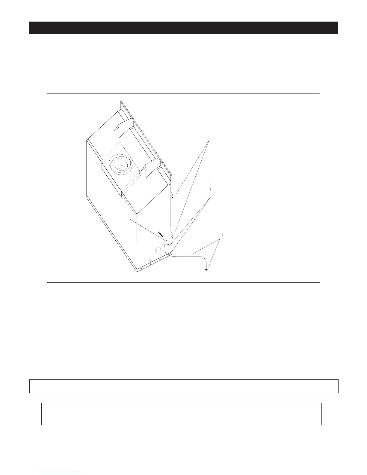
An appliance must be grounded to the steel chassis of the home with 8 ga. copper wire using a serrated or
star washer to penetrate paint or protective coating to insure grounding.
Use carriage bolt at the attachment point (see diagram above) to secure the appliance to the floor.
Warning: Do not compromise the structural integrity of the manufactured home wall, floor or
ceiling, during installation of appliance or venting.
For required venting components see venting installation in appropriate section of this manual.
APPLIANCE MUST BE SECURED TO STRUCTURE
USING SUPPLIED NAIL TABS AND OR FASTEN TO
FLOOR
USE EXISTING HOLE OR REMOVE EXISTING SCREW TO MOUNT GROUND WIRE
(FAN MOUNT HOLE OR OUTER WRAP SCREW)
GROUND WIRE FROM APPLIANCE
TO STEEL CHASSIS OF MOBILE
HOME. USE 8 GA COPPER WIRE.
SERRATED OR
STAR WASHER
Certified for installation in a bedroom or bedsitting room. In Canada must be installed with listed milli volt thermostat. In USA see local codes.
5
Installation and Operation
Installation Regulations
This gas appliance must be installed by a qualified installer in accordance with local building codes, or in the absence of local codes, with
the current CAN/CGA-B149.1 or .2 Installation Code (in Canada) or
the current National Fuel Gas Code Z223.1 when installed in the
United States.
This appliance, when installed, must be electrically connected and
grounded in accordance with local codes, or in the absence of local
codes, with the current CSA C22.1 Canadian Electrical Code or with
the national Electrical Code; ANSI/NFPA 70-1987 when installed in the
United States.
FOR SAFE INSTALLATION AND OPERATION OF
YOUR GAS FIREPLACE PLEASE NOTE THE
FOLLOWING:
1. This appliance gives off high temperatures and should be located out of heavy traffic areas and away from furniture and
draperies.
2. Children and adults should be alerted to the hazards of the high
surface temperatures of this appliance and should stay away to
avoid burns or ignition of clothing.
3. Children should be carefully supervised when they are in the
same room as your fireplace appliance.
4. Under no circumstances should this appliance be modified. Any
parts that have to be removed for servicing should be replaced prior
to operating this appliance.
5. Installation and any repairs to this appliance should be done by
a qualified service person. A professional service person should
be called to inspect this appliance annually. Make it a practice
to have all your gas appliances checked annually.
6. Control compartments, burners and air passages in this appliance should be kept clean and free of dust and lint. Make sure
that the gas valve and pilot light are turned off before you
attempt to clean this unit.
7. The venting system (chimney) of this appliance should be inspected
at least once a year and if needed, your venting system should be
cleaned.
8. Clothing or other flammable material should not be placed on
or near the appliance. This appliance should not be used as a
drying rack for clothing nor should Christmas stockings or decorations be hung from it.
9. Under no circumstances should any solid fuels (wood, paper) be
used in this appliance.
10. For safe operation, glass doors must be closed.
11. Do not use this heater if any part has been under water. Immediately
call a qualified service technician to inspect the heater and to
replace any part of the control system and any gas control which
has been under water.
12. Do not operate appliance unless completely installed as per
installation instructions.
13. WARNING: Do not operate appliance with the glass front
removed, cracked or broken. Replacement of glass should be done
by a licensed or qualified service person.
Operating and Maintenance Instructions
This gas appliance should be installed by a qualified installer in accordance with local building codes and with current CAN/CGA - B149
(.1 or .2) installation codes for Gas Burning Appliances and Equipment.
For safe installation and operation
note the following:
Never use your gas fireplace as a cooking device.
The Burner/Log Assembly has been engineered and permanently
adjusted for proper flame control.
Periodically remove the logs from the grate assembly and vacuum any
loose particles from the grate and burner areas.
Control compartments, burners and air passages in this appliance
should be kept clean and free of dust and lint. Make sure that the gas
valve and pilot light are turned off before you attempt to clean this unit.
See Log Placement on Pages 10-20 to remove logs, vacuum burner
parts and replace logs.
Note: It is normal for your gas fireplace to give off some odor the
first time it is burned. This is due to the curing of the paint and any
undetected oil from the manufacturing process.
Please ensure that your room is well ventilated - open all windows.
It is recommended that you burn your gas fireplace for at least four (4)
hours the first time you use it without the fan on.
Warning: When purging the gas line, the glass front must be
removed.
Do not alter gas orifice.
6
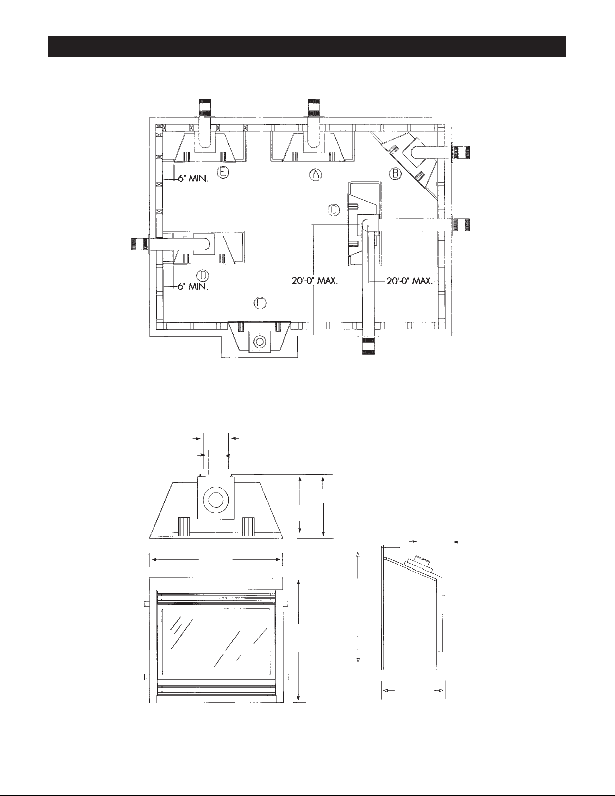
Locating your Appliance
(above or below grade)
Installing with Slope Top Vent
Island installation with a top vent is possible as long as the horizontal portion of the vent system does not exceed 20 feet (6.1m). When you install
your fireplace as in position ‘B’, ‘D’ or ‘E’, a minimum of 6 inches (153mm) clearance must be maintained from the perpendicular wall and the
front of the appliance.
A - Flat on a wall D - As a room divider
B - Across the corner E - Flat on wall corner
C - As an island F - Exterior wall
7"
4"
16.75"
16.25"
42"
36"
36"
6"
16.75"
7
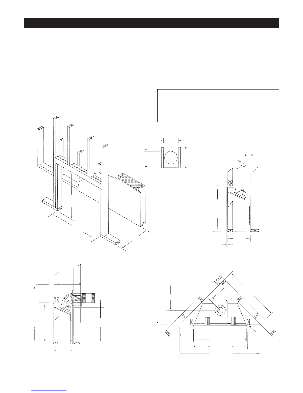
Framing for your Gas Fireplace
Framing Specifications
1. Cold climate installation recommendation: When installing this fireplace
against non insulated exterior wall or chase, it is recommended that the
outer walls be insulated to conform to applicable insulation codes. Drywall
should be installed over insulation to prevent contact of insulation and unit.
2. Choose fireplace location and frame in accordance with the fireplace framing dimensions specified (See Framing Diagrams). Bend nailing tabs forward on left and right of unit and place fireplace into framed enclosure. This
allows for 1/2” in front of framing tabs for finishing materials.
3. Drywall or other material can extend flush with the appliance on the
bottom, sides and top of fireplace.
4. When installing horizontal with a 90 degree bend maintain a minimum of
2
1
/2 inches (64mm) above the bend in enclosures.
5. Hearth is not mandatory but is recommended for aesthetic purposes.
Combustible floors cannot raise above the bottom of the fireplace.
We
recommend a non-combustible hearth projecting out 12” (305mm)
or more in front of the fireplace.
44"
MINIMUM
36.187"
17"
35"
36.188"
42.375"
17"
8.65" DIA. 11"
36.188"
17"
30.656"
MINIMUM OF 1"
CLEARANCE TO
COMBUSTIBLES
MINIMUM FROM
BASE TO CENTER
OF TERMINATION
20.843"
14.75"
43.375"
9.5"
42"
42.375"
61.375"
NAILING
TABS
.50" For Gyprock
Facing
“MUST”
MAINTAIN
1" CLEARANCE
TO COMBUSTIBLES
11"
TOP VIEW
It is recommended for Propane Horizontal Installations that the
venting should be a minimum of one foot vertical off the flue
before the elbow on any horizontal runs of one foot or greater.
This allows for cleaner combustion and greatly reduces carboning
and cleaning of glass. (Does not apply to Back Flue Models).
8
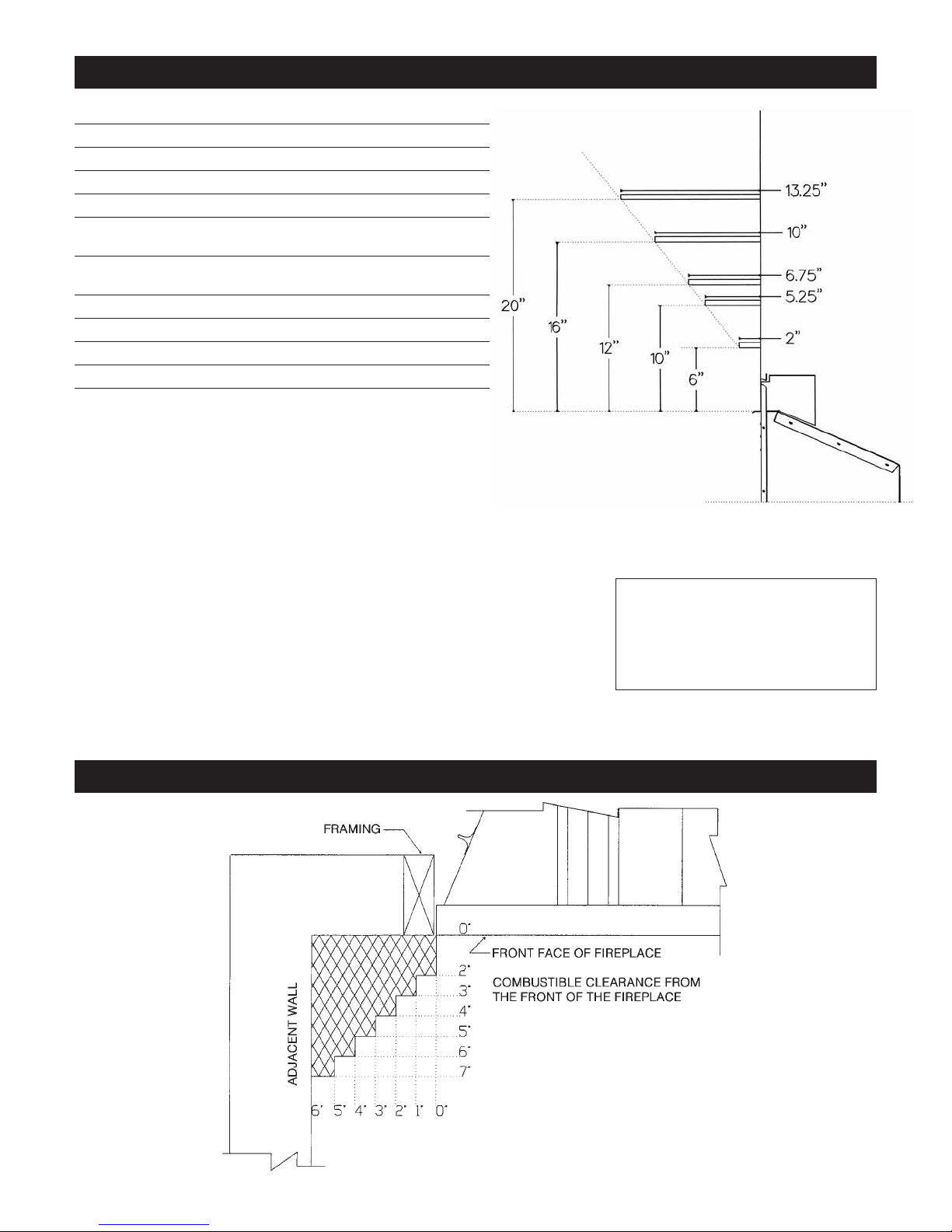
Mantel Leg Clearances
Clearances to Combustibles
Mantels
Depending on the depth of the fireplace mantel, it may be installed higher or lower from the top
of the fireplace opening. See drawings for proper installation height of your combustible
mantel. Non-combustible mantels may be installed at any height above the fireplace opening.
Non combustible materials such as brick, tile, etc. can extend up to or over the front face of the
fireplace (NO PORTION OF GRILLAREA OR DOOR AREAS CAN BE COVERED).
Combustible material can extend flush to unit up to the top, bottom and sides of fireplace to
stand-offs.
If slim line brass surround is used, brick, tiles or other NON-COMBUSTIBLE materials may
extend past the front of unit giving a recessed appearance. For COMBUSTIBLE materials
extending in front of fireplace consult (Mantel and Mantel Leg Drawings).
If wide brass surround is used finish materials must be flush with front of unit.
Note: When using paint or lacquer to finish the mantel, such paint or lacquer must be heat
resistant (250˚F) to prevent discoloration.
Warning: Combustible objects must not be
placed on a non-combustible mantel unless
the non-combustible mantel meets the
minimum height and width requirements for
a combustible mantel.
Clearance to Combustibles
Back (from Standoffs) 0 inches/0 mm
Side (from standoffs) 0 inches/0 mm
Floor 0 inches/0 mm
Top (from standoffs) 0 inches/0 mm
Top of 90 degree bend in Minimum
Enclosure of 44 inches 51/2 inches/140 mm / Kingsman Vent Systems
Top of 90 degree bend in
Enclosure over 44 inches 21/2 inches/64 mm / Kingsman Vent Systems
Top of Horizontal Pipe 11/2 inches/38 mm / Kingsman Vent Systems
Side & Bottom of Horizontal Pipe 1 inch/25.5mm / Kingsman Vent Systems
Vertical Vent Pipe 1 inch/25.5mm / Kingsman Vent Systems
Vertical Vent Pipe 11/4 inch/32mm / Simpson Duravent Systems
(NOTE -Floor) if installing the appliance directly on carpeting or other
combustible materials other than wood flooring, the appliance shall be
installed on a metal or wood panel, the full width and depth of the appliance.
Carpet may extend 1/2 inch above the floor of appliance.
Note: See Mantel Chart
This gas appliance should be installed by a qualified installer in accordance with local
building codes and with current CAN/CGA - B149.1 or .2 installation codes for Gas
Burning appliances and equipment in Canada and the National Fuel Gas Code ANSI
Z223 in the U.S.A.
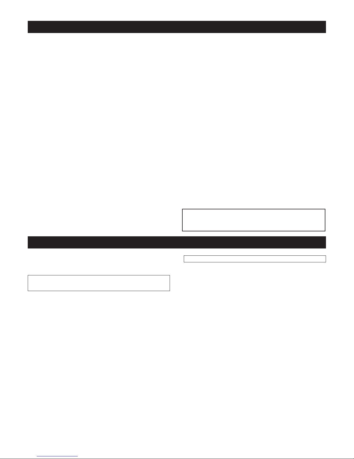
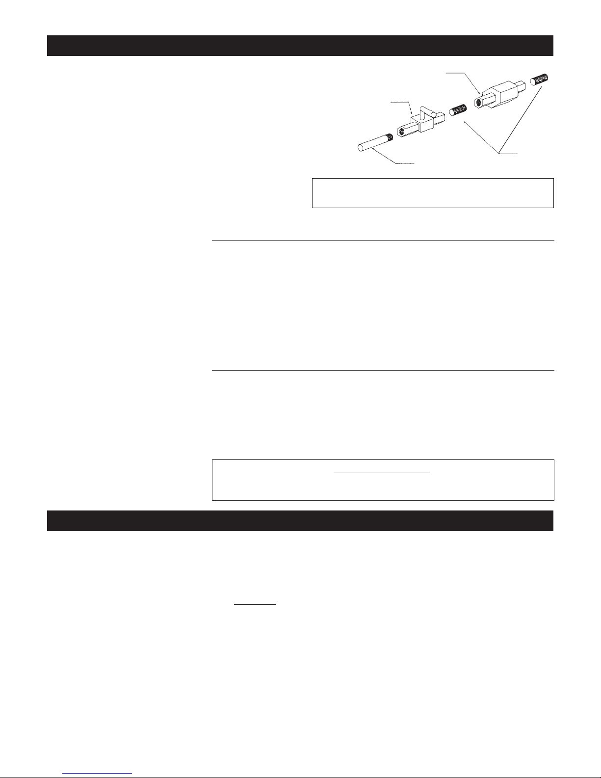
1. The gas pipeline can be brought in through either the right or the left side of the
appliance. A knockout is provided at either location to allow for the gas pipe
installation and testing of any gas connection.
2. The gas control inlet is 3/8” NPT. Typical installation layout for rigid pipe is
shown at right.
3. When using copper or flex connector, use only approved fittings. Always provide a union so that gas line can be easily disconnected for burner or fan servicing. See gas specification for pressure details and ratings.
4. When a vertical section of gas pipe is required for
the installation, a condensation trap is needed. See
CAN/CGA-B149.1 or .2 for code details.
5. For natural gas, a minimum of 3/8” iron pipe with
gas minimum pressure of 4.5 w.c. must be used
for supply from the gas meter. Consult with the
local gas utility if any questions arise concerning pipe sizes.
6. A 1/8” NPT plugged tappings are accessible for
test gauge connection both on the inlet and outlet
of the gas valve.
7. Turn the gas supply ON and check for leaks. DO
NOT USE OPEN FLAME FOR THIS PURPOSE.
Use an approved leak testing solution.
8. The appliance and its individual shutoff valve
must be disconnected from the gas supply piping
system during any pressure testing of that system
at test pressures in excess of 1/2 PSIG (3.5 KPa).
9. The appliance must be isolated from the gas supply piping system by closing its individual shutoff
valve during any pressure testing of the gas supply piping system at test pressures equal to or less
than 1/2 PSIG (3.5 KPa).
Note: The gas line connection may be made of 1/2”
rigid pipe, 1/2” copper pipe or an approved flex
connector. Since some municipalities have additional local codes, it is always best to consult your
local authorities and the current CAN/CGA B149.1 or .2 installation code in Canada or the
National Fuel Gas code ANSI Z223.1 in the U.S.A.
9
General Glass Information
Glass Cleaning
It will be necessary to clean the glass periodically. During start-up,
condensation, which is normal, forms on the inside of the glass and
causes dust, lint etc. to cling to the glass surface. Also, initial paint
curing can deposit a slight film on the glass. It is therefore recommended
that initially the glass be cleaned two or three times with non-abra
sive
common household glass cleansers and warm water. After that, the
glass should be cleaned two or three times a season depending on the
circumstances.
Cautions and Warnings
• Do not clean when the glass is hot.
• The use of substitute glass will void all product warranties.
• Care must be taken to avoid breakage of the glass.
• Do not operate this fireplace without the glass front or with a broken
glass front.
• Do not strike or abuse glass.
Glass Replacement
REPLACEMENT GLASS FOR BOTH DIRECT VENT UNITS
Model ZDV4224N and ZDV4224LP can use either tempered glass or
Robax ceramic or coated Neaoceram glass. Must be 5mm thick.
Only Robax ceramic or coated Neaoceram glass may be used for replacement for Model ZDV4228N, ZDV4228LP, ZDV4232N and
ZDV4232LP. Must be minimum 5mm thick.
Removal of the Glass Door
1. Remove the two screws located behind upper grill or unfasten latches if so equipped.
2. To remove, pull frame forward and lift from bottom door retainer.
3.
To replace glass, clean all materials from door frame. Using a high
heat silicone temperature-resistant to 500°F (260°C) apply a bead of
approximately 1/32” to all four sides of frame and insert glass with
new gasket. Frame should be on flat surface, with a small amount of
weight pressing glass into silicone. Let dry approximately 15 to 20
minutes. The door can be re-installed by reversing Steps 1 & 2.
Gas Line Installation
Gas Specifications
Models ZDV4224N ZDV4224LP ZDV4228N ZDV4228LP ZDV4232N ZDV4232LP
Fuel Natural Propane Natural Propane Natural Propane
Gas Control Millivolt adjustable Millivolt adjustable Millivolt adjustable Millivolt adjustable Millivolt adjustable Millivolt adjustable
Maximum 24,000 BTU High 22,000 BTU High 28,000 BTU High 26,000 BTU High 30,500 BTU High 29,200 BTU High
Input 14,000 BTU Low 15,000 BTU Low 20,000 BTU Low 19,000 BTU Low 20,600 BTU Low 22,200 BTU Low
Maximum n/a n/a 21,000 BTU High 19,500 BTU High 22,900 BTU High 21,900 BTU High
Output
Orifice Size #42 #53 #37 #52 #36 #51
(0 - 4500 ft)
Air Shutter 1/8” Open Fully Open .218” Open Fully Open .187 .312
.25” .625” Open/
Gas Inlet Size S.I.T. 820 Nova, 3/8” NPT
Gas Supply Pressure Minimum Normal Maximum
Natural Gas 5.5” 7” 9”
Liquid Propane 11” 11” 12”
Manifold Pressure Natural Gas Liquid Propane
Manifold Pressure High 3.5 IN. W.C./.87 KPa 10 IN. W.C./2.61 KPa
Manifold Pressure Low 1.6 IN. W.C./.40 KPa 6.3 IN. W.C./1.57 KPa
3/8” UNION
3/8” NIPPLE
1/2” x 3/8” SHUTOFF VALVE
1/2” GAS SUPPLY
For the state of Massachusetts a T-handle gas shut-off valve must be used on a gas appliance.
This T-handle gas shut-off valve must be listed and approved by the state of Massachusetts.
This is in reference to the state of Massachusetts state code CMR238.
Important: Always check for gas leaks with a soap and water solution. Do not use
open flame for leak testing.
 Loading...