

Page 1
Installation Instructions
Listed Certified for USA. and Canada
Certified to: ANSI Z21.44a-1992, Can1-2.19-M81, CGA I.R.#41, CGA I.R.#55, CAN/CGA 2.17-1991
Model Number ZDV1001
Stock #’s: ZDV 360, 960, 1160, 1560, 1960, 2560
“Zero Clearance”
Direct Vent Gas Fireplace
Read this complete manual before beginning installation.
These instructions must be kept with the unit for future reference.
FOR YOUR SAFETY
Do not store or use gasoline or other flammable vapors and liquids in the
vicinity of this or any other appliance.
What T
o Do If You Smell Gas
Do not try to light any appliance.
Extinguish any open flame.
Do not touch any electrical switch.
Do not use any phone in your building.
Immediately call your gas supplier from a neighbour’s phone.
If you can not reach your gas supplier, call the fire department.
KINGSMAN INDUSTRIES
A Division of R-Co. Inc.
3 Winfield Way
Winnipeg, Manitoba, Canada R2R 1V8
Phone (204)-632-1962
Warning: Improper installation, alteration, service or maintenance can cause property damage, personal
injury or losses of life. Refer to this manual. Installation and service must be performed by a qualified
installer, service agency or the gas supplier.
Printed in Canada 05/96 Part # 1000-P920CP Revision 2
Page 2

2
Installation and operation . . . . . . . . . . . . . . . . . . . . . . . . . . . .3
Locating your appliance . . . . . . . . . . . . . . . . . . . . . . . . . . . . .4
Framing your gas fireplace . . . . . . . . . . . . . . . . . . . . . . . . .4,5
Gas line installation . . . . . . . . . . . . . . . . . . . . . . . . . . . . . . . . .5
Operating and maintenance instructions . . . . . . . . . . . . . . . . .6
General glass information . . . . . . . . . . . . . . . . . . . . . . . . . . . .6
Log assembly and fan kit . . . . . . . . . . . . . . . . . . . . . . . . . . . .7
Fan kit installation . . . . . . . . . . . . . . . . . . . . . . . . . . . . . . . . . .7
Millivolt system, lighting, & burner control . . . . . . . . . . . . . .8
Vent termination . . . . . . . . . . . . . . . . . . . . . . . . . . . . . . . . .9,10
Venting graph . . . . . . . . . . . . . . . . . . . . . . . . . . . . . . . . . . . .10
General vent installation information . . . . . . . . . . . . . . . . . .11
Installation of top flue side wall venting . . . . . . . . . . . . .11,12
Installation of back vents . . . . . . . . . . . . . . . . . . . . . . . . . . .13
Repair parts list . . . . . . . . . . . . . . . . . . . . . . . . . . . . . . . . . . .13
Valve System Parts . . . . . . . . . . . . . . . . . . . . . . . . . . . . . . . .13
Kingsman Fireplace part numbers &
specifications Options . . . . . . . . . . . . . . . . . . . . . . . . . . . . . .14
Kingsman Fireplace accessories . . . . . . . . . . . . . . . . . . . . . .14
Kingsman Fireplace options . . . . . . . . . . . . . . . . . . . . . . . . .14
Kingsman Fireplace venting . . . . . . . . . . . . . . . . . . . . . . . . .14
Trouble shooting the gas control system . . . . . . . . . . . . . . . .15
Kingsman Industries Gas Fireplace – Limited Warranty . . .16
Table of Contents
Page 3
3
Installation and Operation
Installation Regulations
This gas appliance must be installed by a qualified installer in accordance with local building codes, or in the absence of local codes, with
the current CAN/CGA-B149.1 or .2 Installation Code (in Canada) or
the current National Fuel Gas Code Z223.1 when installed in the
United States.
This appliance, when installed, must be electrically connected and
grounded in accordance with local codes, or in the absence of local
codes, with the current CSA C22.1 Canadian Electrical Code or with
the national Electrical Code; ANSI/NFPA 70-1987 when installed in the
United States.
FOR SAFE INSTALLATION AND OPERATION OF
YOUR GAS FIREPLACE PLEASE NOTE THE FOLLOWING:
1. This appliance gives off high temperatures and should be located
out of heavy traffic areas and away from furniture and draperies.
2. Children and adults should be alerted to the hazards of the high surface temperatures of this appliance and should stay away to avoid
burns or ignition of clothing.
3. Children should be carefully supervised when they are in the same
room as your fireplace appliance.
4. Under no circumstances should this appliance be modified. Any
parts that have to be removed for servicing should be replaced prior
to operating this appliance.
5. Installation and any repairs to this appliance should be done by a
qualified service person. A professional service person should be
called to inspect this appliance annually. Make it a practice to have
all your gas appliances checked annually.
6. Control compartments, burners and air passages in this appliance
should be kept clean and free of dust and lint. Make sure that the
gas valve and pilot light are turned off before you attempt to clean
this unit.
7. The venting system (chimney) of this appliance should be inspected
at least once a year and if needed, your venting system should be
cleaned.
8. Keep the area around your appliance clear of combustible materials,
gasoline and other flammable vapors and liquids. This appliance
should not be used as a drying rack for clothing nor should
Christmas stockings or decorations be hung from it.
9. Under no circumstances should any solid fuels wood, paper) be
used in this appliance.
10. For safe operation, glass doors must be closed.
11. Do not use this heater if any part has been under water. Immediately
call a qualified service technician to inspect the heater and to
replace any part of the control system and any gas control which
has been under water.
12. Do not operate appliance unless completely installed as per installation instructions.
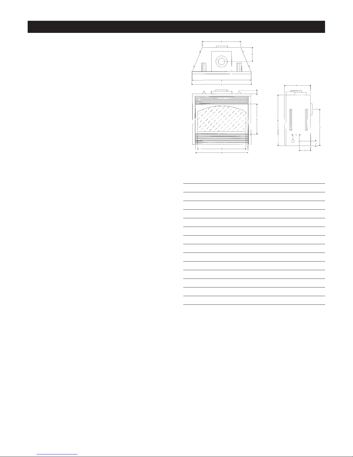
Dimension Top Vent Back Vent
A 23 1/2” 23 1/2”
B 36” 36”
C 36 3/4” 36 3/4”
D 7 1/4” Top Vent only
E 31 3/4” 31 3/4”
F 15” 15 1/4”
G Back Vent Only 22 7/8”
H 5 7/8” 5 7/8”
I 5 1/8” 5 1/8”
J 2 7/8” 2 7/8”
K 2” 1/2”
L 19 1/8” 19 1/8”
M 29 3/4” 29 3/4”
N 32 1/4” 32 1/4”
Note: Pipe diameters for both the back vent and top vent are 4” for
the inner pipe 7” for the outer pipe.
Page 4
4
Locating your Appliance
(above or below grade)
Installing with Top Vent Option
Island installation with a top vent is possible as long as the horizontal portion of the vent system does not exceed 10 feet (305cm). When you install
your fireplace as in position ‘B’, ‘D’ or ‘E’, a minimum of 6 inches
(153mm) clearance must be maintained from the perpendicular wall and
the front of the appliance.
(above grade)
Installing with Back Vent Option
A - Flat on a wall D - As a room divider
B - Across the corner E - Flat on wall corner
C - As an island F - Exterior wall
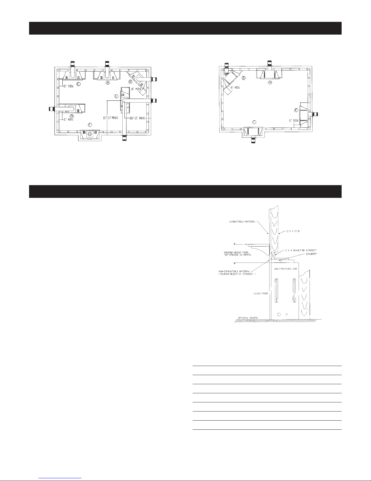
Framing for your Gas Fireplace
Framing Specifications
1. Choose fireplace location and frame in accordance with the fireplace dimensions specified on page one of this manual. When using
a wide 3.5 in. surround the fireplace must be 1/2” (13mm) ahead of
the wall. Also allowances must be made for drywall tile or any other
facing used around the unit. When using Slim Line Brass surround
or no surround fireplace face maybe built out from the framing
specification using non combustible materials such as brick or
stone, giving a reset appearance.
2. Place fireplace into position and secure to floor with 1 1/2” screws
or nails. Nailing tab located left and right lower side of fireplace.
3. Cold climate installation recommendation: when installing this fireplace against non-insulated exterior wall or chase, it is recommended that the outer walls be insulated to conform to applicable insulation codes. Drywall should be installed around the unit to prevent
insulation from contacting the body.
4. Drywall can extend flush with the appliance on the bottom and sides
of the fireplace. A non-combustible material must be used to extend
flush with the top of the fireplace and must have a vertical length
equivalent to the height of the standoffs.
5. If you are installing the top vent unit with a 90˚ bend, the minimum
clearance to combustibles directly above the 90˚ bend is 4”
(102mm).
6. Non-combustible materials such as brick and tile can be extended
across the face of the fireplace. If wide 3.5” brass trim kit is going
to be installed, brick and tile will have to be installed flush with the
front of this appliance. If slim line brass trim kit is used, brick or
tile may extend past the front of unit.
Hearth
A hearth is not mandatory but is recommended for aesthetic purposes.
We recommend a non-combustible hearth projecting out 12” (305mm)
or more in front of the fireplace.
Clearance to Combustibles
Back (from Standoffs) 0 inches/0 mm
Side (from standoffs) 0 inches/0 mm
Floor 0 inches/0 mm
Top (from standoffs) 0 inches/0 mm
Top (from front of unit) 2.5 inches/64 mm
Top of 90 Bend 4 inches/102 mm
Top of Horizontal Pipe 2.5 inches/64 mm
Note: See Mantel Chart
Page 5
5
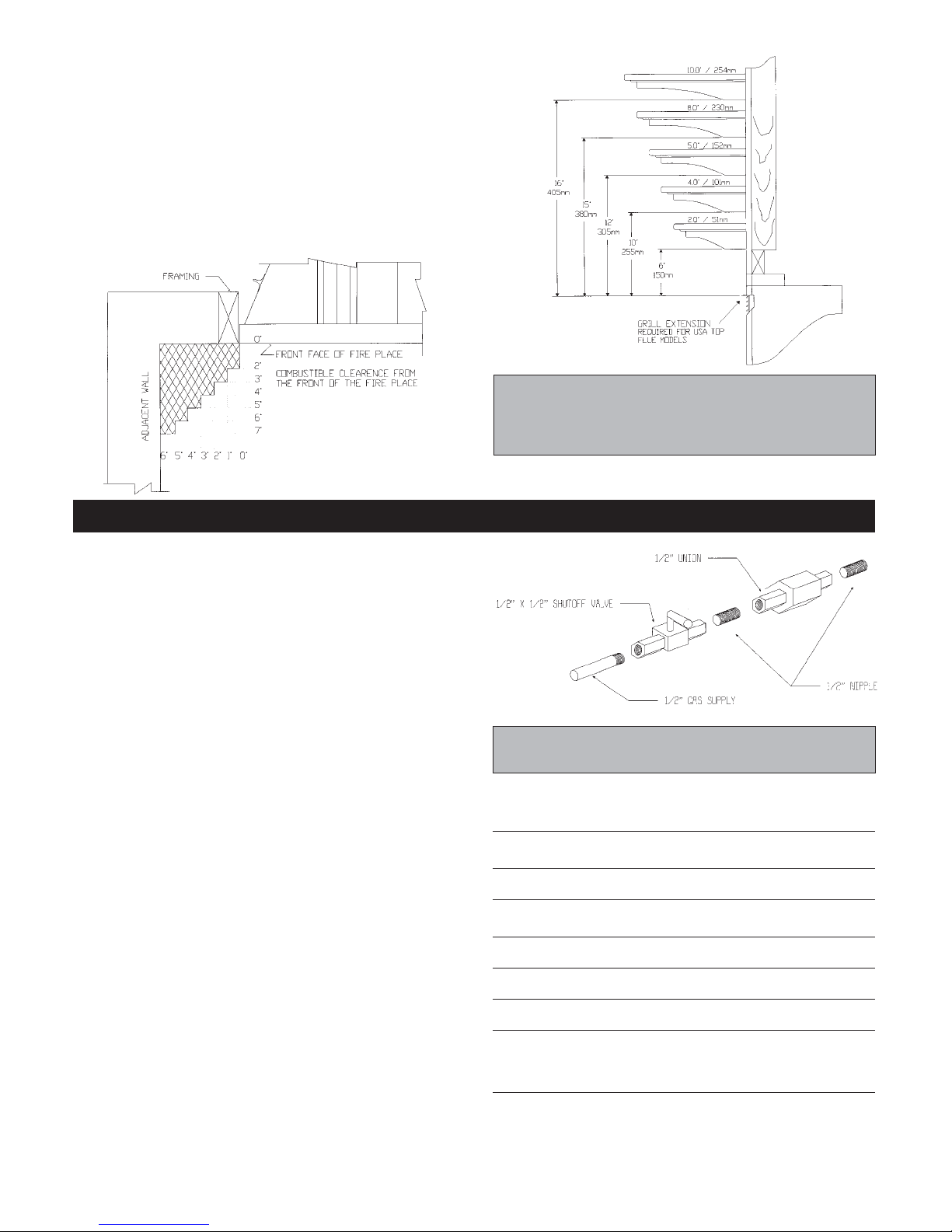
Gas Line Installation
This gas appliance should be installed by a qualified installer in accordance with
local building codes and with current CAN/CGA - B149.1 or .2 installation codes for
Gas Burning appliances and equipment in Canada and the National Fuel Gas Code
ANSI Z223 in the U.S.A.
1. The gas pipeline can be brought in through either the right or the left side of the
appliance. A knockout is provided at either location to allow for the gas pipe
installation and testing of any gas connection.
2. The gas control inlet is 1/2” NPT. Typical installation layout for rigid pipe is
shown at right.
3. When using copper or flex connector, use only approved fittings. Always provide a union so that gas line can be easily disconnected for burner or fan servicing. See gas specification for pressure details and ratings.
4. When a vertical section of gas pipe is required for the installation, a condensation trap is needed. See CAN/CGA-B149.1 or .2 for code details.
5. For natural gas, a minimum of 3/8” iron pipe with gas minimum pressure of 4.5
w.c. must be used for supply from the gas meter. Consult with the local gas utility if any questions arise concerning pipe sizes.
6. A 1/8” NPT plugged tappings are accessible for test gauge connection both on
the inlet and outlet of the gas valve.
7. Turn the gas supply ON and check for leaks. DO NOT USE OPEN FLAME
FOR THIS PURPOSE. Use an approved leak testing solution.
8. The appliance and its individual shutoff valve must be disconnected from the gas
supply piping system during any pressure testing of that system at test pressures
in excess of 1/2 PSIG (3.5 KPa).
9. The appliance must be isolated from the gas supply piping system by closing its
individual shutoff valve during any pressure testing of the gas supply piping system at test pressures equal to or less than 1/2 PSIG (3.5 KPa).
Note: The gas line connection may be made of 1/2” rigid pipe, 1/2” copper pipe
or an approved flex connector. Since some municipalities have additional local
codes, it is always best to consult your local authorities and the current
CAN/CGA - B149.1 or .2 installation code in Canada or the National Fuel Gas
code ANSI Z223.1 in the U.S.A.
Gas Specifications
Model Fuel Gas Control Maximum Input
ZDV1001 Natural Millivolt
(adjustable) 27500 BTU High
18500 BTU Low
ZDV1001 Propane Millivolt
(adjustable) 27000 BTU High
20000 BTL Low
Gas Inlet White Rodgers 1/2” NPT
Gas Supply Minimum Normal Maximum
Pressure (inches water column)
Natural Gas 4.5 7.0 9.0
Propane Gas 10.8 11.0 12.0
Manifold Natural Gas 3.5 inches water column
Pressure Propane Gas 10.5 inches water column
Orifice Size Natural Gas (0-2000 ft) Front 52, Rear 46
Natural Gas (2000-4500 ft) Front 53, Rear 47
Propane Gas (0-2000 ft) Front 66, Rear 54
Propane Gas (2000-4500 ft) Front 66, Rear 55
Mantles
Depending on the width of the fireplace mantle, it may be installed
higher of lower from the top of the fireplace opening. See drawing and
chart below for proper installation height of your combustible mantelpiece. Non-combustible mantles may be installed at any height above
the fireplace opening.
When installing the top vented unit in the United States, a grill extension must be used. The grill extension should extend 1” (25mm) from
the front face.
Note: When using paint or lacquer to finish the mantle, such paint
or lacquer must be heat resistant (250˚F) to prevent discoloration.
Warning: Combustible objects must not be placed on a non-com-
bustible mantle unless the non-combustible mantle meets the minimum height and width requirements for a combustible mantle.
Important: Always check for gas leaks with a soap and water solution. Do not use
open flame for leak testing.
Page 6

6
Operating and Maintenance Instructions
This gas appliance should be installed by a qualified installer in accordance with local building codes and with current CAN/CGA - B149 (.1
or .2) installation codes for Gas Burning Appliances and Equipment.
For safe installation and operation
note the following:
This appliance gives off high temperatures and should be located out of
heavy traffic areas and away from furniture and draperies.
Children and adults should be alerted to the hazards of high surface
temperatures of this appliance and should stay away to avoid burns or
ignition of clothing.
Under no circumstances should this appliance be modified. Parts that
have to be removed for servicing should be replaced prior to operating
this appliance again.
Installation and any repairs to this appliance should be done by a qualified service person. A professional service person should be called to
inspect this appliance annually. Make it a practice to have all of your
gas appliances checked annually.
Never use your gas fireplace as a cooking device.
The Burner/Log Assembly has been engineered and permanently
adjusted for proper flame control.
Periodically remove the logs from the grate assembly and vacuum any
loose particles from the grate and burner areas.
Control compartments, burners and air passages in this appliance
should be kept clean and free of dust and lint. Make sure that the gas
valve and pilot light are turned off before you attempt to clean this unit.
The venting system (chimney) of this appliance should be inspected at
least once a year and if needed, your venting system should be cleaned.
Keep the area around your appliance clear of combustible materials,
gasoline and other flammable vapors and liquids.
This appliance should not be used as drying rack for clothing, nor
should Christmas stockings or decorations be hung near it.
Under no circumstances should any solid fuels (wood, paper, cardboard, coal) be used in this appliance.
Note: It is normal for your gas fireplace to give off some odor the
first time it is burned. This is due to the curing of the paint and any
undetected oil from the manufacturing process.
Please ensure that your room is well ventilated - open all windows.
It is recommended that you burn your gas fireplace for at least four (4)
hours the first time you use it without the fan on.
Warning: When purging the gas line, the glass front must be
removed.
Do not alter gas orifice.
General Glass Information
Glass Cleaning
It will be necessary to clean the glass periodically. During start-up, condensation, which is normal, forms on the inside of the glass and causes
dust, lint etc. to cling to the glass surface. Also, initial paint curing can
deposit a slight film on the glass. It is therefore recommended that initially the glass be cleaned two or three times with non-abrasive
common household glass cleansers and warm water. After that, the glass
should be cleaned two or three times a season depending on the circumstances.
Cautions and Warnings
• Do not clean when the glass is hot.
• The use of substitute glass will void all product warranties.
• Care must be taken to avoid breakage of the glass.
• Do not operate this fireplace without the glass front or with a broken
glass front.
• Do not strike or abuse glass.
Glass Replacement
REPLACEMENT GLASS FOR BOTH DIRECT VENT UNITS
Only Robax ceramic or coated Neaoceram glass may be used for
replacement. Must be minimum 5mm thick.
Removal of the Glass Door
1. Remove the two screws located behind upper grill.
2. To remove, pull frame forward and lift from bottom door retainer.
3. To replace glass, clean all materials from door frame. Using a high
heat silicone (temperature-resistant to 500˚F (260˚C) apply a bead
of approximately 1/4” to all four sides of frame and insert glass
with new gasket. Frame should be on flat surface, with a small
amount of weight pressing glass into silicone. Let dry approximately 15 to 20 minutes. The door can be re-installed by reversing Steps
1 & 2.
Page 7

7
Log Assembly & Fan Kit
Log Assembly
1. Remove glass door by removing two (2) screws behind upper grills
and lifting door off bottom door retainer.
2. Remove logs from carton (4) and inspect.
3. Rear log should be installed onto rear log holder attached to back of
firebox above and to the rear of the burner pan.
4. Front log should be centered on the log supports between the front
and rear burners. Push log against the back of the supports.
5. Top logs can then be placed across the front and back logs in the
slots provided.
6. Purge lines and test pilot operation.
7. Spread supplied rocks evenly on front burner, being careful not to
get rock in the crossover tube opening below the front log. Next,
tear ember wool into small, thin, irregular pieces and place it evenly
over rocks.
8. Replace glass door. The door must be installed before operating the
fireplace.
Fan Kit Installation
Automatic On/Off Thermostat Controlled
Fan Kit (Part # ZIFK)
1. Open the lower front access cover.
2. Remove the two (2) sensor mounting screws located to the right of
the control valve in the access area on the bottom side of the fire
box. Secure the sensor unit under the fire box being sure to tighten
the screws so the sensor is in contact with the fire box bottom.
3. Insert the two (2) #8x1/2 screws provided with the fan into the
holes in the side of the fireplace opposite the gas line entry. Mount
the fan using the keyhole slots in the fan body.
4. Install a junction box (type to except three prong plug) on the inside
wall of the access area opposite the fan. Large holes are provided to
allow wiring to enter the access area on the left of the unit. Connect
the power, sensor and variable speed wall switch as shown in the
wiring diagram.
Note: If the fan has been installed on the left of the unit it will be
necessary to lengthen the sensor unit leads to reach the sensor.
Install as per diagram.
5. Close lower access cover.
6. Turn the wall switch on (clockwise). Turn the fireplace on. Once the
sensor unit reaches operating temperature in approximately 10 to 15
minutes the fall will turn on. The fan can be switched off, if desired,
by turning the wall switch fully counter-clockwise.
7. To set the minimum fan speed if desired. Remove the variable speed
switch from the wall mount. Turn the variable speed wall controller
to its minimum setting (fully clockwise). Use the set screw on the
side of the variable speed controller to increase or decrease the minimum fan speed. (It may be desirable to lower minimum fan speed
to decrease the sound level created by the fan.) Reinstall switch into
wall mount and cover with face plate.
Electrical Services
All optional fan kits are equipped with a 120V, 60Hz blower.
Note: All electric connections are to be made in accordance with CSA
Standard C22.1 - Canadian Electrical Code part I or with the National
Electrical Code, ANSI/NFPA 70 (latest addition) and/or in accordance
with local codes.
Recommended Maximum Lead Length
(Double Wire) When Using Wall Switch or
Thermostat
Wire Size Max. Length
14 GA. 100 FT.
16 GA. 64 FT.
18 GA. 40 FT.
20 GA. 25 FT.
22 GA. 16 FT.
Caution: Should this fan require servicing, the power supply must be disconnected.
Page 8

8
Millivolt System, Lighting, & Burner Control
Lighting Instructions
1. Open access grill on bottom.
2. Push in gas control knob slightly and turn clockwise to “OFF”.
NOTE: Knob cannot be turned from “PILOT” to “OFF” unless knob is
pushed in slightly. Do not force.
3. Wait five (5) minutes to clear out any gas remaining in burner combustion chamber.
4. Turn knob on gas control counter-blockwise to “PILOT”.
5. Push in control knob all the way and hold in. Immediately light the
pilot with piezo-electric ignitor while continuing to push knob in for
one (1) minute. Release knob. Pilot should remain lit. If it goes out,
repeat steps 2 through 5 until pilot remains lit.
– If knob does not pop up when released, stop and immediately call
your service technician or gas supplier.
– If pilot will not stay lit after several tries, turn the gas control
knob to “OFF” and call your service technician or gas supplier.
6. Turn gas control knob counter-clockwise to “ON”.
7. All models are supplied with a wall switch that
turns the main burner on or off. If main burner does
not light immediately when you turn the gas control
valve to “ON” ensure that the wall switch is in the
“ON” position.
NOTE: The “On/Off” wall switch may be replaced
with a wall thermostat allowing main burner to
light and turn off automatically depending upon
thermostat setting and room temperature.
8. Adjust the gas flow (flame height) with the
HI/LOW gas control knob on valve.
NOTE: Standard gas control valve without
HI/LOW is designed to be either fully on or fully
off. It should never be used to vary flame height or
adjust gas flow.
– LP valve is non-adjustable.
– NG valve is adjustable with HI/LOW control
knob.
9. Close control access grill.
Pilot Burner
Adjustment
1. Remove pilot adjustment cap.
2. Adjust pilot screw to
provide proper sized
flame.
3. Replace pilot adjustment cap.
4. Leak Test.
To Turn Off Gas Appliance
Turn off all electric power to the appliance if service is to be performed. Open control access grill.
Push in gas control knob slightly and turn clockwise to “OFF”. Do not
force. Close control access grill.
Caution: Do Not Wire 120 Volt Power To Millivolt Switches Or Thermostats.
THERMOCOUPLE
OR GENERATOR
Page 9

9
Vent Termination
Vent Terminal
Air Supply
Area Where Terminal Not Permitted.
A - Clearance above grade, veranda, porch, deck, or balcony 12 inches
(30cm) minimum.
1
B - Clearance to window or door that may be opened. 12 inches (30cm)
minimum for appliances 100 000 Btuh (30 kW) and lower.
C - Clearance to permanently closed window minimum 12 inches (30cm)
recommended to prevent condensation on window.
D - Vertical clearance to ventilated soffit located above the terminal within
a horizontal distance of 2 feet (60cm) from the center line of the terminal. 18 inches (46cm) minimum.
E - Clearance to unventilated soffit 12 inches (30cm) minimum.
F - Clearance under veranda, porch, deck or balcony 12 inches
1
(30cm)
minimum.
2
G - Clearance from a perpendicular inside wall to the edge of the vent
terminal is 14” (35.5cm).
H - Not to be installed above a meter/regulator assembly within 3 feet
(90cm) horizontally from the center line of the regulator.
I - Clearance to service regulator vent outlet 6 feet (1.8m) minimum.
1
J - Clearance to non-mechanical air supply inlet to building or the
combustion air inlet to any other appliance 12 inches (30cm) minimum for appliances 10 000 Btuh (30kW) and lower, 36 inches
(90cm) minimum for appliances greater than 100 000 Btuh
(30kW).
K - Clearance to a mechanical air supply inlet 6 feet (1.8m) minimum.
1
L - Clearance above paved sidewalk or a paved driveway located on
public property 7 feet (2.1m) minimum.
3
V
NOTE: Clearances are to the terminal center line. Add 6 inches to
clearances not indicated as measured from center line.
NOTE: Local Codes or Regulations may require different clearances.
Termination
It is imperative that the vent termination be located observing the minimum clearances as shown. There must not be any obstruction such as
bushes, garden sheds, fences, decks or utility buildings within 24” from
the front of the termination.
Do not locate termination where excessive snow or ice build-up may
occur. Be sure to check vent termination area after snow falls and clear
to prevent accidental blockage of venting system. When using snow
blowers, make sure snow is not directed towards vent termination area.
General Venting Information
The gas fireplace is approved to be vented either through the side wall
or vertically through the roof.
ONLY VENTING COMPONENTS SPECIFICALLY APPROVED
AND LABELLED FOR THIS FIREPLACE MAY BE USED.
Minimum clearance between vent pipes and combustible materials is 1
inch (25mm).
NOTE: Clearance between vent pipe and combustibles at the wall
thimble is 2 inches (50mm).
Venting terminal shall not be recessed into a wall or siding.
1 - As specified in CGA B149 installation codes (1991).
2 - Only permitted if veranda, porch, deck, or balcony is fully open on a minimum of two
sides beneath the floor.
1
3 - A vent shall not terminate directly above a sidewalk or paved driveway which is located
between two single family dwellings and serves both dwellings.
Page 10

10
Venting Routes And Components
Since it is very important that the vent system maintain its balance
between the combustion air intake and the flue gas exhaust, certain limitations as to vent configurations apply and must be strictly adhered to.
The table showing the relationship between vertical and horizontal side
wall venting will help to determine the various vent lengths.
The maximum horizontal vent run with the 90 degree bend to the fireplace flue outlet is 3 feet (91cm) Figure 1. The maximum horizontal
vent run is 10 feet (305cm) when the vertical rise is 8 feet (244cm)
Figure 2. Note: 1/4” vertical rise is required for every 12” of horizontal
run.
The maximum number of 90 degree bends per side wall installation is
one (1).
The maximum number of 45 degree bends per side wall installation is
two (2). These bends can be installed in either the horizontal or vertical
run.
Maximum vertical rise is 20 feet (6.09 meters).
Special Note: For each 45 degree bend installed in the horizontal
run, the length of the horizontal run must be reduced by 18”
(45cm). This does not apply if the 45 degree bends are installed on
the vertical part of the vent system.
Example: If according to the table, the length of the horizontal run is
10 feet, and two 45 degree bends are required, the horizontal run length
must be reduced to 7 feet.
How To Use The Vent Table
1. Determine the height of the system and the number of bends
required.
2. Having determined the vertical distance determine the maximum
horizontal section allowed.
3. Vent table has been established for 90˚ horizontal/vertical runs.
With use of flex pipe distance not having 90˚ bends will not fall into
vent table standards. See Fig. B.
Venting Table For Top Vent Models
for venting to a maximum of 20 ft. (6.09meters)
Sidewall or Vertical Venting (See Fig. A & B)
Total Vertical Max Total Horizontal
Feet Meters Feet Meters
4 1.2 3 0.9
5 1.5 4 1.2
6 1.8 6 1.8
7 2.1 8 2.4
8 2.4 10 3.0
9 2.7 11 3.4
10 3.0 12 3.7
11 3.4 13 4.0
12 3.7 14 4.3
13 4.0 15 4.6
14 4.3 16 4.9
15 4.6 15 4.6
16 4.9 14 4.3
17 5.2 13 4.0
18 5.5 12 3.7
19 5.8 11 3.4
20 6.1 10 3.0
Example A:
If the vertical dimension from
the floor of the fireplace is
6.5ft, the horizontal run to the
wall flange of the vent termination must not exceed 7.5ft.
NOTE: The final location of
the fireplace must be such
that the horizontal vent
dimensions fall within those
stated on the graph. The
Maximum Vertical vent run is
20 feet (6.09meters).
Important: Always locate the fireplace in such a way that a minimum of off-
sets and/or horizontal runs are required. 1/4” vertical rise is required for every
12” horizontal run.
Important: Minimum clearance between vent pipes and
combustible materials is 1 inch
(25mm).
7.5
6.5
Page 11

11
General Vent Installation Information
Flex Pipe Venting
Flex pipe is shipped in unexpanded length. When installing pipe
expand the lengths. Pipe can be expanded to twice their lengths e.g. 4ft.
to 8ft.
Do not use more than 2 couplers to extend short pipes. Single sections
are preferred in an installation attaching at the fireplace and termination.
Place the spring spaces provided approximately every two feet to stabilize 4” flex in the center of 7” flex. When forming bends place spring
in bend or before and after. (See Fig. 1).
Horizontal runs require support metal straps every 2 feet. In off set
installation support straps should be used to stabilize pipe.
Expand 4” and 7” flex pipe to the point that the 7” protrudes approximately 2 to 3 inches past outer wall and the 4” flex protrudes approximately 2 to 3 inches past the 7” flex. See Fig. 1. Attach the 4” pipe to
the termination first and secure with sealant and clamp and screw then
attach the 7” flex to the termination with caulking and clamp and
screw. Termination may then be moved back to the other wall and
attached to home screwing into the framing. Silicone around termination to waterproof. If siding shied is going to be used attach at this time
using same attaching hole at tope of terminations after termination has
been caulked for water proofing.
Use Term Hi Temp Sealant
Apply a bead of mill pack high temp caulking to all joints and clamp
with screwtype clamps provided at fireplace, termination and any joint
if joining any sections of pipe.
Installation Of Top Flue Side Wall Venting
Step 1
Locate vent opening on the wall. Cut a hole through the exterior wall
allowing for a 11” x 11” minimum inside framing or an 8 1/2” diameter
hole if venting through a non-combustible wall. Center wall thimble
over 11” x 11” framing to route vent pipes through thimble and wall.
See Fig. 2.
Select the approximate vent length, precise measurement s are not
needed as your flex pipe can expand to twice its shipped length for ease
of installation.
Before joining pipes, apply a bead of high temperature sealant (Mill
Pac) to end of pipe. Attach four inch (4”) flue pipe to fireplace with
sealant and clamp and screws first, then attach the seven inch (7”)
flange ring to fireplace with sealant and clamp and screws, and then
attach the seven inch (7”) pipe by the same method. Join pipes and
secure joints with sealant and clamp.
Step 2
Mount vent termination and seal to wall using caulking around the wall
thimble to weatherproof. After installing the vent termination, double
check to make sure the pipe extends properly through wall thimble and
into vent termination.
NOTE: Clearance to combustibles above an 90˚ bend is 4 inches
(10.2cm)
Step 3
Support horizontal pipes every two (2) feet (61cm) with metal pipe
straps. Re-check fireplace to make sure it is levelled and properly positioned, and nailed or screwed to the floor.
NOTE: It is critical to the proper and safe operation of this fireplace that on all
connections the inner liner and the outer casing are both caulked with liberal
amounts of sealant. Do not use any kind of tape or silicone other than that recommended in this manual. Mill Pac Sealant
FRAMING DIMENSION
Combustible Wall
Cut a 11” hole through exterior wall and frame as shown below.
Non combustible Wall
Cut or drill 8.5” or 216mm diameter hole.
COMBUSTIBLE FRAMING
FOR WALL THIMBLE
FIGURE 1
FIGURE 2
Page 12

12
Using Flex Bends
4. Avoid cutting joists by offsetting the flex pipe. See Fig. 2.
5. Maximum horizontal offset when using 45˚ bends is 6 feet.
6. When using 45˚ bends an bend support is required directly above
the highest bend.
7. Never install a bend in a joist area. Vent sections must pass vertically through framed joist areas.
8. Maximum vertical height of system should not exceed 20 feet.
9. Use roof support and 7” ridge pipe at roof level. Flex not permitted
with in roof support.
10. When penetrating the roof a ridge 7” pipe must be used. Attach the
7” flex to the 7” ridge with high temperature sealant, clamp security
with adjustable clamp, and use two screws/washers either above or
below camp assuring the flex and ridge pipe are secured. 4” flex
pipe must be secured the same way with 2 screws and washers
either above or below the clamp but must penetrate the 4” flex and
4” section of termination. Attach 7” ridge to 7” termination with
sealant and screw with 3 sheet metal screws. (See Fig. 3).
Roof Flashing
Ensure that you have the proper roof flashing by checking your roof
pitch using a level and two rulers, or by using a roof pitch card. See figure below.
Slide a Roof Flashing suitable to your roof slope over the vent. Place
the edge of the flashing plate that will be on the higher part of the roof
slope under the shingles. Both the sides and the lower edge lay on top
of the shingles.
NOTE: At the top edge of the flashing plate, lift the shingles and
nail the plate to the roof deck, then cement the shingles to the plate
with a suitable waterproof mastic.
Ensure that the chimney is plumb. Square up the flashing plate and nail
in place to the roof deck. Use 12 nails with neoprene washers or cover
the heads with a suitable waterproof mastic.
Wrap the storm collar around the vent above the flashing. Secure the
ends together loosely with nut and bolt supplied. Slide the collar down
the vent until it comes in contact with the flashing. Tighten the bolt and
seal the Storm Collar to the vent with a suitable waterproof non-combustible mastic.
The flashing and storm collar should be painted to match the roof shingles. This will extend its life and improve the appearance. Clean, prime
and paint the suitable painting products.
Continue adding lengths of vent until the proper height is achieved (See
diagram above). Slide raincap into vent.
FIG. 1
FIG. 2
Venting Straight Up Through Roof
1. An Attic Insulation Shield must be installed where the vent passes
from a lower living space into an attic space where the chimney is
not enclosed. It is designed to keep insulation materials away from
the chimney. See Fig. 1.
2. When installing the Attic Insulation Shield where the chimney passes from a living space to an attic space, install the shield from
below and nail in place using 1” spiral nails.
3. A fire stop must be installed on the bottom side of the joists when
passing through a ceiling or floor. If an attic insulation shield is to
be used, a fire stop is not required.
FIG. 3
Page 13

13
Installation of Back Vents
Repair Parts List
General Back Vent Installation and Specification
Straight Back max vent length 36” Vent Kit # ZDVHSK
45˚ Corner Max Number of 45˚ Bends One
Vent Kit #s FDVHT, ZDVWT, ZDVFK4
Max Vent Length after 45˚ Bend 18”
See Fig. 1 & 2 Page 13
NOTE: Minimum clearance between vent pipes and combustible
materials is one inch or 25mm.
Step 1
Locate vent opening on the wall. COMBUSTIBLE WALLS cut a 11” x
11” (280mm x 280mm) minimum hole and frame as shown. NONCOMBUSTIBLE WALL hole opening must be 8.5” (216mm) in diameter. Install wall thimble for vent pipe routing through wall. See Fig. 3.
Step 2
Place fireplace into place and attach vent pipes, four inch (4”) first.
Make sure pipes are pushed on securely. Champs, sealed and screwed.
Step 3
Straight Back Venting. Measure wall thickness. If wall is thinner than
(1Ft.) then1 foot unexpanded length in ZDVHSK must be expanded
add cut. 7” should extend post outer wall approximately 2” to 3” and 4”
flex approximately 2” past the 7” flex then allows enough room to
secure pipe to termination with high heat sealants, clamp and screw, the
press termination back to outer wall and seal. Place spacer spring over
4” flex to stabilize it in the 7” flex if length is over a foot.
Step 4
Cover Back Venting. Only one - 45˚ bend per installation. Install as
per above length. May not exceed Figure 1 page 13 and must be cut to
comply.
Install wall thimble.Place fireplace into place and secure to floor with
nailing tabs.
Step 5
Mount vent termination, make sure 4” and 7” pipes are siliconed. Caulk
around wall thimble to weatherproof.
Corner Installation
Location
NOTE: When the fireplace
is installed cross corner it is
necessary to bend. Use Kit
#FDVHSK, ZDVWT,
ZDVFK4.
Burner Assembly - Complete
1001 - BNGWR NG Burner Assembly (with thermocouple wired
directly to valve)
1001 - BLPWR LP Burner Assembly (with thermocouple wired
directly to valve)
Valve System Parts
Natural Gas Valve System
(with thermocouple wired directly to valve
1000 - P133WR Valve NG Hi/Lo (36D33U-100)
1000 - P134WR Pilot Burner (E39A1)
1000 - P135WR Thermocouple (H19E924)
1000 - P136WR Generator (GO1A-524)
1000 - 206 Pilot Orifice (F069-2060)
LP Gas Valve System
(with thermocouple wired directly to valve
1000 - P101WR Valve LP Hi/Lo (36D33U-101)
1000 - P134WR Pilot Burner (E39A1)
1000 - P135WR Thermocouple (H19E924)
1000 - P136WR Generator (GO1A-524)
1000 - P104WR Pilot Orifice LP (F069-2462)
Miscellaneous Parts
1000 - 134 Gasket for Explosion Disk
1000 - 214 Piezo Electric Spark Ignitor
1000 - 218 On/Off Switch (Wall Mount)
1000 - 227 On/Off Cover Plate
1000 - 255 - 46 Back Burner Orifice NG - (0-2000 ft)
1000 - 255 - 47 Rear Burner Orifice NG - (2000-4500 ft)
1000 - 255 - 52 Front burner Orifice NG - (0-2000 ft)
1000 - 255 - 53 Front Burner Orifice NG - (2000-4500 ft)
1000 - 255 - 54 Rear Burner Orifice Lp - (0-2000 ft)
1000 - 255 - 55 Rear Burner Orifice LP - (2000-4500 ft)
1000 - 255 - 66 Front Burner Orifice LP - (0-4500 ft)
1000 - 301 Straight Door Frame
FIG. 3
FIG. 1
FIG. 2
Page 14

14
1000 - 302 Arch Door Frame
1000 - 305 Glass - Robax or coated Neoceram
1000 - 306 Gasket - Door
1000 - EMBER Ember Kit
1000 - 700 Log Set (4 Pieces)
1000 - 085 Variable Speed Wall Mount Switch
2000 - 080 Sensor for Auto On/Off Fan Kit
Kingsman Fireplace Part Numbers
and Specifications Options
Product Description
Number
ZDV1160 Zero Clearance Fireplace (natural gas) Top Vent,
Arch Door
ZDV2560 Zero Clearance Fireplace PROPANE Top Vent,
Arch Door
ZDV360 Zero Clearance Fireplace (natural gas) Back Vent,
Straight Door
ZDV960 Zero Clearance Fireplace (natural gas) Back Vent,
Arch Door
ZDV1560 Zero Clearance Fireplace (natural gas) Top Vent,
Straight Door
ZDV1960 Zero Clearance Fireplace PROPANE Top Vent,
Straight Door
Kingsman Fireplace Accessories
Catalog
Number Description
ZIFK Fan Kit (Thermostatic On/Off)
ZIRL Refractory Kit
ZIRC Cordless Remote Control
ZIMT Thermostat Wall Mount Millivolt
Kingsman Fireplace Options
Catalog
Number Description
Grills
ZIGBL Grills - Black
ZIGAB Grills - Antique Brass
ZIGPB Grills - Polish Brass
ZIGAL Grills - Almond
ZIGBG Grills - Burgundy
ZIGGR Grills - Green
Surround Kits
ZISAB Surround - Antique Brass
ZISPB Surround - Polish Brass
ZISAL Surround - Almond
ZISBG Surround - Burgundy
ZISGR Surround - Green
ZISSAB Surround (Slim Line) - Antique Brass
ZISSPB Surround (Slim Line) - Polish Brass
Arch Door Frame
ZIADAB Arch Door Frame - Antique Brass
ZIADPB Arch Door Frame - Polish Brass
ZIADAL Arch Door Frame - Almond
ZIADBG Arch Door Frame - Burgundy
ZIADGR Arch Door Frame - Green
Kingsman Fireplace Venting
Catalog
Number Description
ZDVHSK Horizontal Vent Starter Kit - (Back Vent)
Starter Kit Contains:
Horizontal Vent Termination, Wall Thimble, 4”-7”
Dia. x 36” Flex Pipe
Clamps, Silicone.
FDVVT15 Vertical Vent Termination (8’ to 15’)
FDVVT30 Vertical Vent Termination (15’ to 30’)
FDVHT Horizontal Vent Termination
ZDVAIS Attic Insulation Shield
ZDVVOS Offset Support
ZDVFS Firestop Spacer
ZDVRS Roof Support
ZDVSS Siding Shield
ZDVWT Wall Thimble (Horizontal Venting)
ZDVAAF Flashing 0/12 - 6/12
ZDVAF2 Flashing 6/12 - 9/12
ZDVAF3 Flashing 9/12 - 12/12
ZDVFK4 Flex Kit (4” & 7” Dia.) x 2’ (Unexpanded) 4’ Expanded
ZDVFK8 Flex Kit (4” & 7” Dia.) x 4’ (Unexpanded) 8’ Expanded
ZDVFK20 Flex Kit (4” & 7” Dia.) x 10’ (Unexpanded) 20’Expanded
*Kits are complete with spring stand-offs, clamps, silicone.
ZDV4FC Flex Connector 4” Diameter
ZDV7FC Flex Connector 7” Diameter
ZDV4FCL Flex Clamp 4”
ZDV7FCL Flex Clamp 7”
Page 15

15
Trouble Shooting The Gas Control System
WARNING: BEFORE DOING ANY GAS CONTROL SERVICE WORK, REMOVE THE GLASS FRONT.
NOTE: Before troubleshooting the gas control system, be sure external gas shut off is in the “On” position.
Problem Possible Causes Corrective Action
Spark igniter will not light. Defective or misaligned electrode Check for spark at electrode and pilot: if no spark and electrode wire is
at pilot. properly connected, replace igniter.
Defective igniter Using a match, light pilot. If pilot lights, turn off pilot and push the red
(push-button) button again. If pilot will not light - check gap at electrode and pilot
should be 1/8” to 1/4” to have a strong spark.
Pilot will not stay lit after carefully Defective thermocouple Check pilot flame. Must impinge on generator and thermocouple.
following lighting instructions. (flame switch where applicable) Clean and/or adjust pilot for maximum flame impingement on
generator and thermocouple.
Defective valve magnet. Replace valve
Pilot burning, no gas to burner, Wall switch or wires Check wall switch and wires for proper connections. Jumper wire
Valve knob “ON”, Wall defective. across terminals at wall switch. If burner comes on, replace defective
Switch “ON” wall switch. If okay, jumper wires, across wall switch wires at valve.
If burner comes on, wires are faulty or connections are bad.
Generator may not be generating Check generator with millivolt meter. Take reading at generator termisufficient voltage. nals of gas valve. Should read 325 millivolts minimum while holding
valve knob depressed in pilot position and wall switch “off” Replace
faulty generator if reading is below specified minimum.
Plugged burner orifice. Check burner orifice for stoppage and remove.
Defective automatic valve Remove wall switch wires from gas valve. Install jumper wires from
operator. top bottom terminals of gas valve. Turn valve on “ON”. If main burner
does not light, replace valve.
Frequent Pilot outage problem. Pilot flame may be too low or Clean and/or adjust pilot flame for maximum flame impingement
blowing (high) causing the pilot on generator and thermocouple.
safety to drop out.
Flame lifts off burner and goes out Inner 4” liner has come off flue Attach 4” liner to flue or termination using
in less than 30 seconds or termination, flame is starving screws, silicone and clamps as stated in manual
oxygen
Flame lifts off burner on Improper installation of firebrick. Be sure to postion firebrick against firebox walls and
one side while the rest of Firebrick is likely leaning. be sure to use brick clips attached to the inner side
the flame remains lit. of firebox.
Page 16

16
This Limited Lifetime Warranty applies only while the unit remains at the site of the original installation and only if the unit is installed inside the
continental United States, Alaska, Hawaii, and Canada. The warranty applies only if the unit is installed and operated in accordance with the printed
instructions and in compliance with applicable installation and building codes and good trade practices.
Basic One Year Warranty
During the first year after installation, we will provide a replacement for any component part of your unit found to be defective in materials or
workmanship, including all reasonable labour costs.
Limited Lifetime Warranty
The heat exchanger, combustion chamber and burner of every Kingsman product are warranted against materials or workmanship during the period
the product is owned by the original owner.
The part to be replaced must be returned to our distributor in exchange for the replacement part. Any labor, material, freight and/or handling charges
associated with any repair or replacement pursuant to this Limited Lifetime Warranty will not be covered by this warranty.
General Terms
In lieu of providing a replacement part, we may, at our option, provide the distributor’s component purchase price from us or a credit equal to the
distributors component purchase price from
us toward the purchase of any new unit which we distribute. If a credit is given in lieu of a replacement part, the rating plate from the unit being
replaced must be submitted on a warranty claim, and the unit being replaced must be made available to our distributor for disposition.
In establishing the date of installation for any purpose, including determination of the starting date for the term of this Limited Lifetime Warranty,
reasonable proof of the original installation date must be presented*, otherwise the effective date will be based upon the date of manufacture plus
thirty (30) days.
We will not be responsible for and you, the user, will pay for: (a) damages caused by accident, abuse, negligence, misuse, riot, fire, flood, or Acts of
God (b) damages caused by operating the unit where there is a corrosive atmosphere containing chlorine, fluorine, or any other damaging chemicals
(other than in a normal residential environment) (c) damages caused by any unauthorized alteration or repair of the unit affecting its stability or
performance (d) damages caused by improper matching or application of the unit or the unit’s components (e) damages caused by failing to provide
proper maintenance and service to the unit (f) any expenses incurred for erecting, disconnecting
or dismantling the unit (g) parts or supplies used in connection with service or maintenance (h) damage repairs, inoperation or inefficiency resulting
from faulty installation or application (i) electricity or fuel costs or any increase in electricity or fuel cost whatsoever including additional or unusual
use of supplemental electric heat.
We shall not be liable for any incidental, consequential, or special damages or expenses in connection with any use or failure of this unit. We have
not made and do not make any representation or warranty of fitness for a particular use or purpose, and there is no implied condition of fitness for a
particular use or purpose. We make no express warranties except as stated in this Limited Lifetime Warranty. No one is authorized to change this
Limited Lifetime Warranty or to create for us any other obligation or liability in connections with this unit. Any implied warranties shall last for one
year after the original installation. Some states and provinces do not allow the exclusion or limitation of incidental or consequential damages or do
not allow limitations on how long an implied warranty or condition lasts, so the above limitations or exclusions may not apply to you. The provisions
of this limited warranty are in additions to and not a modification of or subtraction from any statutory warranties and other rights and remedies
provided by law.
Save this certificate. It gives you specific legal rights, and you may also have other rights which may vary from state to state and province to
province.
In the event your unit needs servicing, contact your dealer or contractor who installed or serviced your unit. When requesting service, please have the
model and serial number from each unit readily available. If your dealer needs assistance, the distributor is available for support and we, in turn
support the distributor’s efforts.
Fill in the installation date and model and serial numbers of the unit in the space provided below and retain this limited warranty for your files.
Model No.
Serial No. Date installed
Dealer or Contractor Name:
*To receive advantage of your warranty, you must retain the original records that can establish the installation date of your unit.
Kingsman Fireplace – Limited Lifetime Warranty
 Loading...