

Kingsman ZDV6000, ZDV3320, MQRB3328, MQRB3328T, ZDV6000N Installation Instructions Manual
...
Installation Instructions
Model Number ZDV6000, ZDV3320
MQRB3328
Zero Clearance Direct Vent Gas Fireplace
Stock #’s ZDV3320N, ZDV3320LP, ZDV3320NE, ZDV3320LPE, are
Certified to: ANSI Z21.50b-2009, CSA 2.22b-2009, CGA 2.17-M91
Stock #’s ZDV6000N, ZDV6000LP, MQRQB3328N, MQRB3328LP
ZDV6000NE, ZDV6000LPE, MQRQB3328NE, MQRB3328LPE are
Certified to: ANSI Z21.88-2009, CSA 2.33-2009, CGA 2.17-M91
INSTALLER: Leave this manual with the appliance.
This appliance may be installed in an aftermarket permanently located, manufactured home (USA only) or mobile
home, where not prohibited by local codes.
This appliance is only for use with the type of gas indicated on the rating plate. This appliance is not convertible for
use with other gases, unless a certified kit is used.
CONSUMER: Retain this manual for future reference.
Read this complete manual before beginning installation.
These instructions must be kept with the unit for future reference.
FOR YOUR SAFETY
WARNING: If the information in these instructions is not followed exactly, a fire or explosion may
result causing property damage, personal injury or loss of life.
Warning: Improper installation, adjustment, alteration, service or maintenance can cause property
damage, personal injury or loss of life. Refer to this manual. Installation and service must be performed by
a qualified installer, service agency or the gas supplier.
Do not store or use gasoline or other flammable vapors and liquids in the vicinity of this or any other appliance.
What To Do If You Smell Gas
Do not try to light any appliance.
Extinguish any open flame.
Do not touch any electrical switch.
Do not use any phone in your building.
Immediately call your gas supplier from a neighbour's phone.
If you can not reach your gas supplier, call the fire department.
For Propane Horizontal installations the venting must be a minimum of one foot vertical off the flue before
going horizontal.
A Division of R-Co. Inc.
2340 Logan Avenue
Winnipeg, Manitoba, Canada R2R 2V3
Ph: (204) 632-1962
Printed in Canada May 8, 2012 Part # 33DV-MAN-II
2
Pre-installation Questions and Answers
About curing of the paint
Your stove or fireplace has been painted with the highest quality silicone stove paint. This paint dries quickly in 15-20
minutes when first applied at the factory. However, due to the high temperature silicone components, the paint will cure
when heat is applied to the appliance as it is first used. The following information applies to the curing process to get the
paint fully hard and durable.
Fire the appliance four successive times for 10 minutes each firing and a 5 minute cool down between each. Be aware
during log and firebox paint curing that a white deposit may be developing on the inside of the glass doors. It is important
to remove this white deposit from the glass doors using a commercial fireplace glass cleaner.
• Babies, small children, pregnant women and pets should leave the area during the cure phase.
• Ventilate well, open doors and windows.
• Do not touch during curing.
Why does my fireplace or stove give off odour?
It is normal for your fireplace to give off some odour. This is due to the curing of the paint, adhesives, silicones and any
undetected oil from the manufacturing process as well as the finishing materials used with the installations (e.g. marble,
tile and the adhesives used to adhere this product to the walls can react with heat and cause odours).
It is recommended that you burn your gas fireplace or stove for a minimum of four hours at a time with the fan off after the
curing of the paint has been completed. These odours can last upward to 40 hours of burn time; keep burning at a
minimum of four hours per use until odours dissipate.
Noise coming from the fireplace?
Noise is caused by the expansion and contraction of metal as the appliance heats up and cools down. This is normal and
is similar to the sounds produced by a furnace or heating duct. This noise does not affect the operation or longevity of
your fireplace.
Operating Instructions
1. Be sure to read and understand all the instructions in this manual before operation of appliance.
2. Ensure all wiring is correct and properly enclosed to prevent possible shock.
3. Check for gas leaks.
4. Make sure the glass door is properly installed before operation. Never operate the appliance with the glass door
removed.
5. Make sure venting and termination cap are installed and unobstructed.
6. If brick or porcelain liners are used, ensure they are installed.
7. Verify that the pilot can be seen when lighting the appliance. If not, the log or rock placement is incorrect.
8. If the unit is turned off, you must wait a minimum of 60 seconds before re-lighting it.
3
Table of Contents
Pre-installation Questions and Answers…………………………………............ 2
Operating Instructions………………………………………………………........... 2
Table of Contents……………………………………………………………........... 3
Mobile Home/Manufactured Housing Installation……………………................ 4
Warnings, Installations, and Operations…………………………………............ 5-6
Installation Requirements for the Commonwealth of Massachusetts…........... 6
Locating your Appliance................................................................................... 7
Fireplace Dimensions....................................................................................... 7
Framing for your Gas Fireplace........................................................................ 8-9
Z33CVCK - Framing and Facing Requirements............................................... 10
33-MVHS Heat Shield for Models ZDV6000, ZDV3320, MQRB3328............... 11-12
How To Install Clean View Kit (CVCK)............................................................. 13
CLEARANCES - ZDV3320/6000/MQRB3328 - Mantels & Surrounds............. 14
ZDV3320/6000/MQRB3328 - Clearance to Combustibles............................... 15
MQ33SW Wall Mount Surround....................................................................... 16
Fan Kit Installation............................................................................................ 17
Split Receptacle- Fan Speed Control Outside of Fireplace.............................. 18
Installing Brick Panel for Model ZDV3320/6000............................................... 19
Installing Porcelain Panel for Model ZDV3320/6000........................................ 19
MQRB3328 Liner Panels.................................................................................. 20
Gas Line Installation......................................................................................... 21
General Glass Information................................................................................ 21
Millivolt System, Lighting, and Burner Control.................................................. 22
Burner System Maintenance............................................................................ 23
Conversion Kit Instructions – PART A.............................................................. 24-25
Gas Conversion for Top Convertible Pilot (Series 019065X) – PART B.......... 26
Gas Conversion for Modulator – PART C......................................................... 27
IPI Electronic Ignition System........................................................................... 28-32
Electronic Ignition Lighting Instructions............................................................ 33
Trouble Shooting The Gas Control System...................................................... 34
Field Conversion for ZDV6000 - VFI25 - VFI30................................................ 35
LOGC5 or LOGF5 Setup for Model ZDV6000.................................................. 36
LOGC6 Setup for Model ZDV6000................................................................... 37
MQROCK1/MQRSP6 Setup for Model ZDV6000............................................. 38-39
LOGC42/LOGC43 Placement Guidelines for Model ZDV3320 (continued)..... 40-41
LOGC44 Placement Guidelines for Model ZDV3320....................................... 41-42
MQROCK1/MQRSP3 Setup for ZDV3320....................................................... 43-44
Accessories Available for Skyline & ZDVRB3622 Ribbon Burner Units........... 45-46
ULK2 Universal Light Kit (Optional Accent Lighting Kit)................................... 47-48
Vent Termination.............................................................................................. 49
General Vent Installation Information............................................................... 50
Installation Of Side Wall Venting...................................................................... 50
Venting Routes And Components.................................................................... 51
How To Use The Vent Table............................................................................ 51
Venting Straight Up Through Roof................................................................... 52
6000 / 3320 / MQRB3328 Parts List................................................................. 53-55
Glass Safety / Termination Cap Safety- All Units............................................. 56
Limited Lifetime Warranty................................................................................. 57
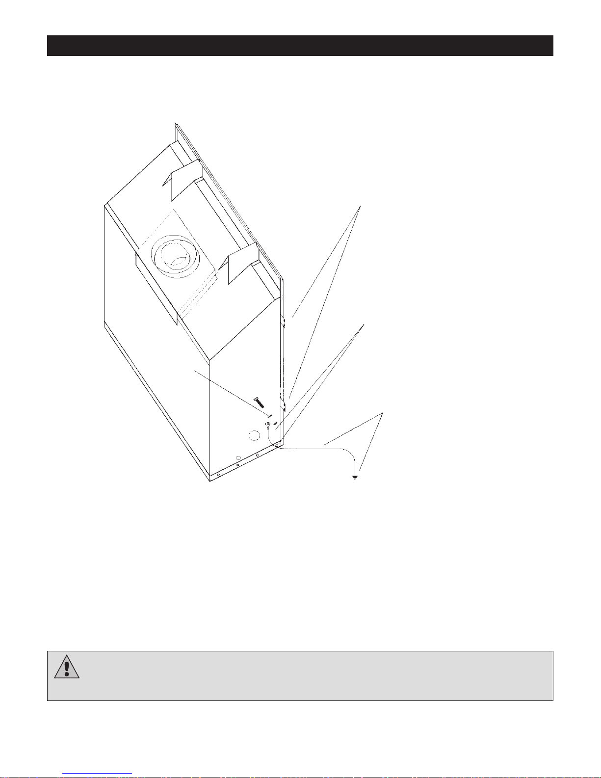
Mobile Home/Manufactured Housing Installation
This Direct Vent System Appliance must be installed in accordance with the manufacturer’s installation instructions and the
Manufactured Home Construction and Safety Standard Title 24 CFR, Part 3280, or the current Standard for Fire Safety Criteria for
Manufactured Home Installations, Sites, and Communities ANSI/NFPA 501A, and with CAN/CSA Z240 MH Mobile Home Standard in
Canada.
THIS APPLIANCE MAY BE INSTALLED IN MANUFACTURED (M0BILE) HOMES AFTER FIRST SALE.
Please follow the current ANSI/NFPA 70 National Electrical Code in the USA and CAN/CSA C22.1 Canadian National Electrical Code in
Canada.
An appliance must be grounded to the steel chassis of the home with 8 ga. copper wire using a serrated or star washer to penetrate
paint or protective coating to insure grounding.
Use carriage bolt at the attachment point (see diagram above) to secure the appliance to the floor.
For required venting components see venting installation in appropriate section of this manual.
APPLIANCE MUST BE SECURED TO STRUCTURE
USING SUPPLIED NAIL TABS AND OR FASTEN TO
FLOOR
USE EXISTING HOLE OR REMOVE
EXISTING SCREW TO MOUNT GROUND
WIRE
(FAN MOUNT HOLE OR OUTER WRAP SCREW)
GROUND WIRE FROM APPLIANCE
TO STEEL CHASSIS OF MOBILE
HOME. USE 8 GA COPPER WIRE.
SERRATED OR
STAR WASHER
WARNING: Do not compromise the structural integrity of the manufactured home wall, floor or ceiling,
during installation of appliance or venting.
4
Warnings, Installations and Operations
5
Installation Regulations
This gas appliance must be installed by a qualified installer in accordance with local building codes, or in the absence of local codes, with the current
CAN/CSA-B149.1 or .2 Installation Code (in Canada) or the current National Fuel Gas Code Z223.1-
This appliance, when installed, must be electrically connected and grounded in accordance with local codes, or in the absence of local codes, with the
current CSA C22.1 Canadian Electrical Code or with the National Electrical Code; ANSI/NFPA 70 when installed in the United States.
In the U.S.A
. Thermostats are not permitted for Vented Gas Fireplaces (ANSI Z21.50b-Decorative).
WARNING
FOR SAFE INSTALLATION AND OPERATION OF YOUR GAS FIREPLACE PLEASE NOTE THE FOLLOWING:
1. Do not clean when the glass is hot.
2. Do not use abrasive cleaners.
3. Using a substitute glass will void all product
warranties.
4. For safe operation, glass doors must be
closed.
5. When purging the gas line, the glass front
must be removed.
6. Do not strike or abuse glass. Take care to
avoid breakage.
7. Do not alter gas orifice.
8. No substitute materials may be used other
than factory supplied components.
9. This appliance gives off high temperatures and should be located out of heavy traffic areas and away from furniture and
draperies.
10. Children and adults should be alerted to the hazards of the high surface temperatures of this appliance and should stay
away to avoid burns or ignition of clothing.
11. Young children should be carefully supervised when they ar e in the same room as the appliance. Toddlers, young children
and others may be susceptible to accidental contact burns. A physical barrier is recommended if there are at risk individuals
in the house. To restrict access to a fireplace or stove, install an adjustable safety gate to keep toddlers, young children and
other at risk individuals out of the room and away from hot surfaces.
12. Under no circumstances should any solid fuels (wood, paper) be used in this appliance.
13. Under no circumstances should this appliance be modified. Any parts that have to be removed for servicing shoul d be
replaced prior to operating this appliance.
14. Any safety screen or guard removed for servicing an appliance must be replaced prior to operating the appliance.
15. Installation and repair should be done by a qualified service person. The appliance should be inspected before use and at
least annually by a professional service person. More frequent cleaning may be requir ed due to excessive lint from
carpeting, bedding material, et cetera. It is imperative that control compartments, burners and circulating air passageways of
the appliance be kept clean. Make sure that the gas valve and pilot light are turned off before you attempt to clean this unit.
16. Clothing or other flammable material should not be placed on or near the appliance. This appliance should not be used as a
drying rack for clothing nor should Christmas stockings or decorations be hung from it.
17. Do not use this heater if any part has been under water. Immediately call a qualified serv ice technician to inspect the heater
and to replace any part of the control system and any gas control which has been under water.
18. Do not operate appliance unless completely installed as per installation instructions.
19. Failure to position the parts in accordance with these diagrams or failure to use only parts specifically approved with this
appliance may result in property damage or personal injury.
20. Do not operate appliance with the glass front removed, cracked or broken. Replacement of the glass should be done by a
licensed or qualified service person.
21. The front of the fireplace gives off high temperatures that could ignite combustible material which is kept close to the front of
the unit.
22. Ensure that power to the Fireplace is turned off before servicing.
23. Do not operate this Fireplace without the glass front or with a broken glass.
24. Improper installation, adjustment, alteration, service or maintenance can cause injury or property damage. Refer to the
owner’s information manual provided with this appliance. For assistance or additional inform ation consult a qualified
installer, service agency, or the gas supplier.
25. Operation of this appliance when not connected to a properly installed and maintained venting system or tampering with the
blocked vent shutoff system can result in carbon monoxide (CO) poisoning and possible death.
26. This appliance is equipped with a three-prong (grounding) p lug for your protection against shock hazard and should be
plugged directly into a properly grounded three-prong receptacle. Do not cut or remove the grounding prong from this plug.
WARNING
NFPA 54 when installed in the United States.
HOT GLASS WILL
CAUSE BURNS
DO NOT TOUCH GLASS
UNTIL COOLED.
NEVER ALLOW CHILDREN
TO TOUCH GLASS.
• Gas fired appliances may be used only for supplemental heat and/or decorative purposes and under no circumstances shall they
6
provide a primary heat source.
• This appliance must not be connected to a chimney flue serving a separate solid-fuel burning ap pliance.
NOTE: It is recommended that a Carbon Monoxide (CO) Detector be installed in or near bedrooms an d on all levels of your home.
Place a detector about 15ft [4.5m] outside the room that houses your gas appliance.
Certified for installation in a bedroom or bed/sitting room. In Canada must be installed with listed millivolt thermostat.
In the U.S.A. Thermostats are not permitted for Vented Gas Fireplaces (ANSI Z21.50b-Decorative).
In USA see local codes.
Operations and Maintenance Instructions
For safe installation and operation note the following:
• Venting systems should be periodically examined by a qualified agency.
• The flow of combustion and ventilation air must not be obstructed.
• The Burner/Log Assembly has been engineered and permanently adjusted for proper fla me control.
• Periodically remove the logs from the grate assembly and vacuum any loose particles from the grate and burner areas. See Log
Placement page to remove logs. Vacuum burner parts and replace logs.
• Never use your gas fireplace as a cooking device.
• Label all wires prior to disconnection when servicing controls. Wiring errors can cause im proper and dangerous operation. Verify
proper operation after servicing.
Installation Requirements for the Commonwealth of
Massachusetts
In the Commonwealth of Massachusetts, the installer or service agent shall be a plumber or gas fitter licensed by the Common wealth.
When installed in the Commonwealth of Massachusetts or where applicable codes; the unit shall be installed with a CO detector per the
requirements listed below.
1. For direct-vent appliances, mechanical-vent heating appliances or domestic hot water equipment, where the bottom of the vent
terminal and the air intake is installed below four feet above grade the following requirements must be satisfied:
A. If there is not one already present, on each floor level where there are bedroom(s), a carbon mon oxide detector and alarm
shall be placed in the living area outside the bedroom(s). The carbon monoxide detector shall comply with NFPA 720.
B. A carbon monoxide detector shall be located in the room that houses the appliance or equipment and shall:
• Be powered by the same electrical circuit as the appliance or equipment such that only one service switch services
both the appliance and the carbon monoxide detector;
• Have battery back-up power;
• Meet ANSI./UL 2034 Standards and comply with NFPA 720; and
• Have been approved and listed by a Nationally Recognized Testing Laboratory as recognized under 527 CMR.
C. A Product-approved vent terminal must be used, and if applicable, a Product-approved air intake must be used.
Installation shall be in strict compliance with the manufacturer’s instructions. A copy of the installation instructions shall
remain with the appliance or equipment at the completion of the installation.
D. A metal or plastic identification plate shall be mounted at the exterior of the building, four feet directly above the location of
vent terminal. The plate shall be of sufficient size to be easily read from a distance of eight feet away, and read “Gas Vent
Directly Below”.
2. For direct-vent appliances, mechanical-vent heating appliances or domestic hot water equipment where the bottom of the vent
terminal and the air intake is installed above four feet above grade the following requirements must be satisfied:
A. If there is not one already present, on each floor level where there are bedroom(s), a carbon mon oxide detector and alarm
shall be placed in the living area outside the bedroom(s). The carbon monoxide detector shall comply with NFPA 720.
B. A carbon monoxide detector shall:
• Be located in the room that houses the appliance or equipment;
• Be either hard-wired or battery powered or both; and
• Shall comply with NFPA 720.
A Product-approved vent terminal must be used, and if applicable, a Product-approved air intake must be used. Installation shall be in
strict compliance with the manufacturer instructions. A copy of the installation instructions shall remain with the appliance or equ ipment
at the completion of the installation.
For the state of Massachusetts a T-handle gas shut-off valve must be used on a gas appliance. This T-handle gas shut-off valve must be listed and
approved by the state of Massachusetts. This is in reference to the state of Massachusetts state code CMR238.
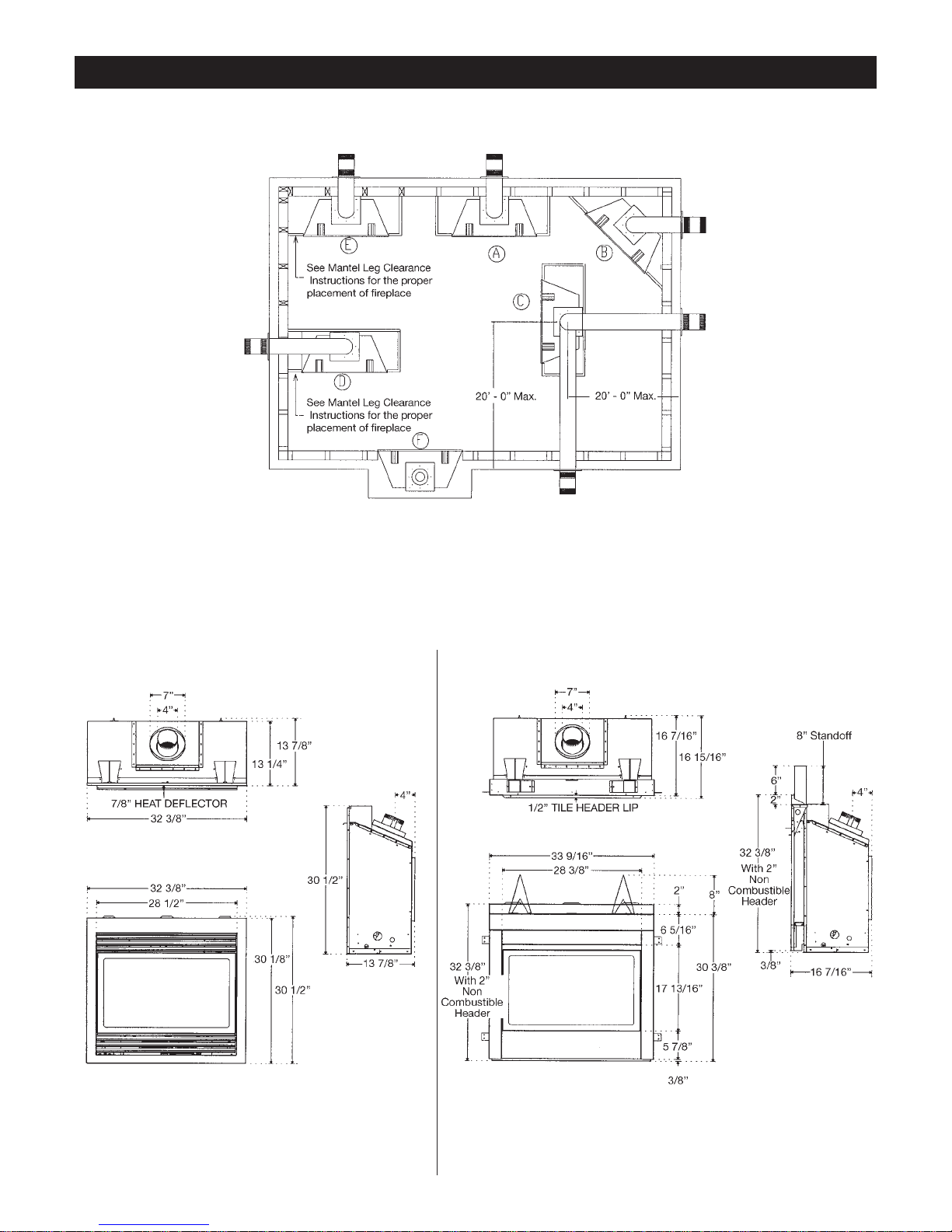
Locating your Appliance
(above or below grade)
Installing with Top Vent
Island installation with a top vent is possible as long as the horizontal portion of the vent system
does not exceed 20 feet (6.1m). When you install your fireplace as in position ‘B’, ‘D’ or ‘E’, a minimum of 6 inches (153mm) clearance must be maintained from the perpendicular wall and the
front of the appliance.
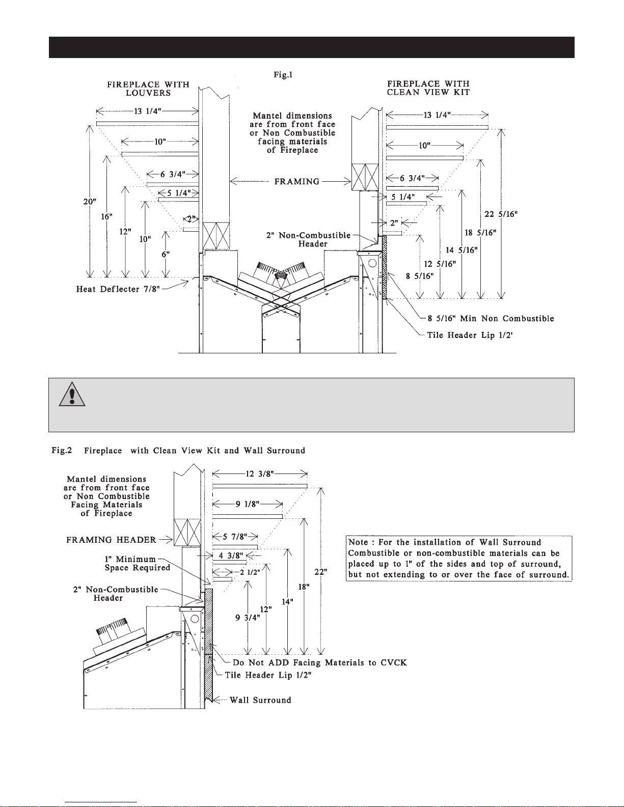
Fireplace Dimensions ZDV3320,
ZDV6000 & MQRB3328 with
Louvers
Fireplace Dimensions ZDV3320,
ZDV6000 & MQRB3328 with
Clean View Kit
7
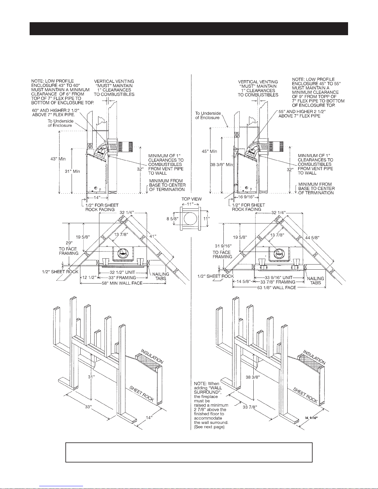
Framing for your Gas Fireplace
8
ZDV3320, ZDV6000 & MQRB3328 with
Louvers
ZDV3320, ZDV6000 & MQRB3328 with
Clean View Kit
Note when using SIMPSON DURAVENT ADAPTER (ZDVDFA) the fireplace clearances
from the back standoff is one inch, thus increasing the framing depth to 15”.
8
Framing for your Gas Fireplace
For Propane Horizontal Installations the venting must
be a minim um of one f oot vertical off the flue bef ore the
elbow on an y horizontal runs of one f oot or g reater. This
allows for cleaner combustion and g reatly reduces carboning and cleaning of glass . (Does not apply to Bac k
Flue Models).
Note when using SIMPSON DURAVENT ADAPTER
(ZDVDFA) the fireplace clearances from the back
standoff is one inch, thus increasing the framing
depth to 15”.
9
9
Framing Specifications
1. Cold climate installation recommendation: When installing this fireplace against non insulated exterior wall or chase, it is recommended that the outer walls be insulated to conform to applicable insulation codes. Drywall should be installed over insulation to prevent contact of insulation and unit.
2. Choose fireplace location and frame in accordance with the fireplace framing dimensions specified (See Framing Diagrams).
Bend nailing tabs forward on left and right of unit and place fireplace into framed enclosure.This allows for 1/2” in front of framing tabs for finishing materials.
3. Drywall or other material can extend flush with the appliance on the bottom, sides and top of fireplace.
4. When installing horizontal with a 90 degree bend maintain a minimum clearance above the bend as shown on Clearance
to Combustibles page.
5. Hearth is not mandatory but is recommended for aesthetic purposes. Combustible floors cannot raise above the bottom of the
fireplace. We rec ommend a non-combustible hearth projecting out 12” (305mm) or more in front of the fireplace.
10
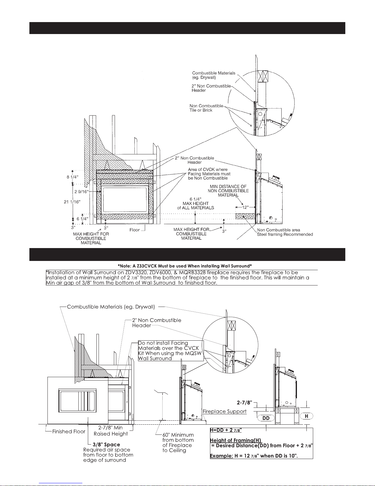
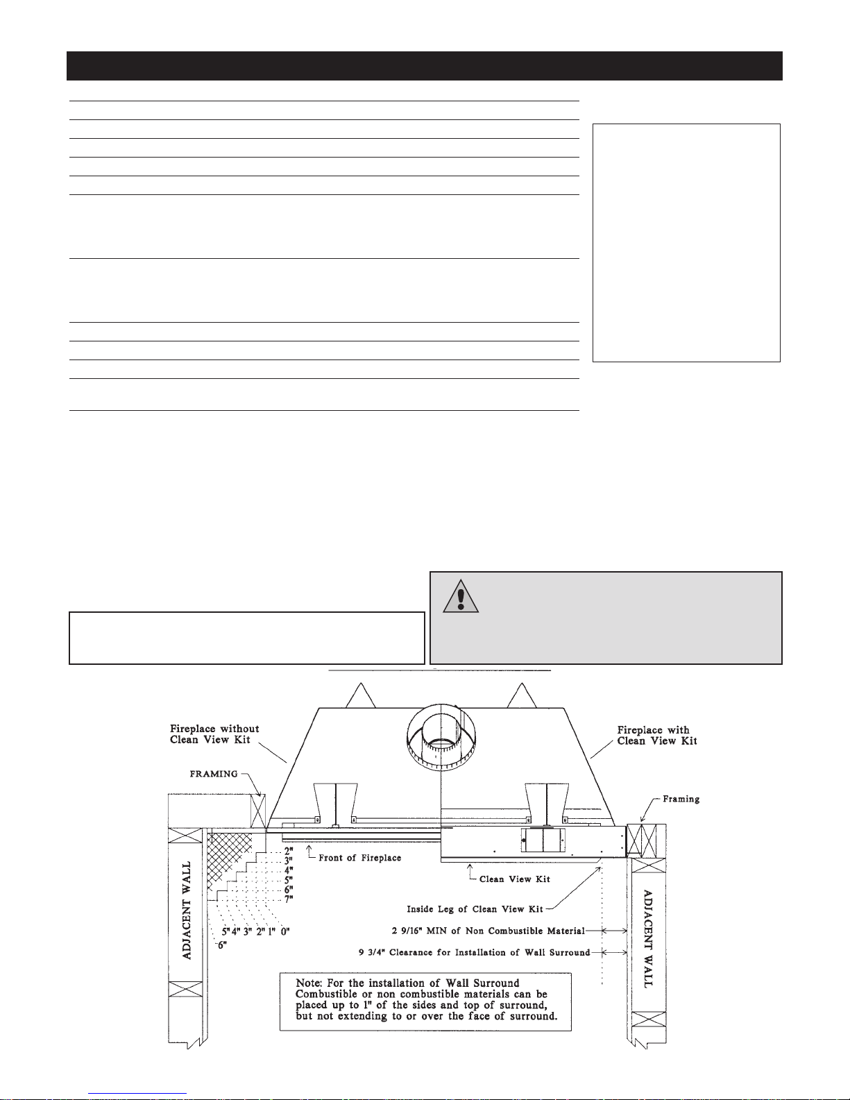
Z33CVCK - Framing and Facing Requirements
ZDV3320, ZDV6000 & MQRB3328 With Z33CVCK
(CLEAN VIEW CIRCULATING KIT)
Z33CVCK - with Wall Surround
10
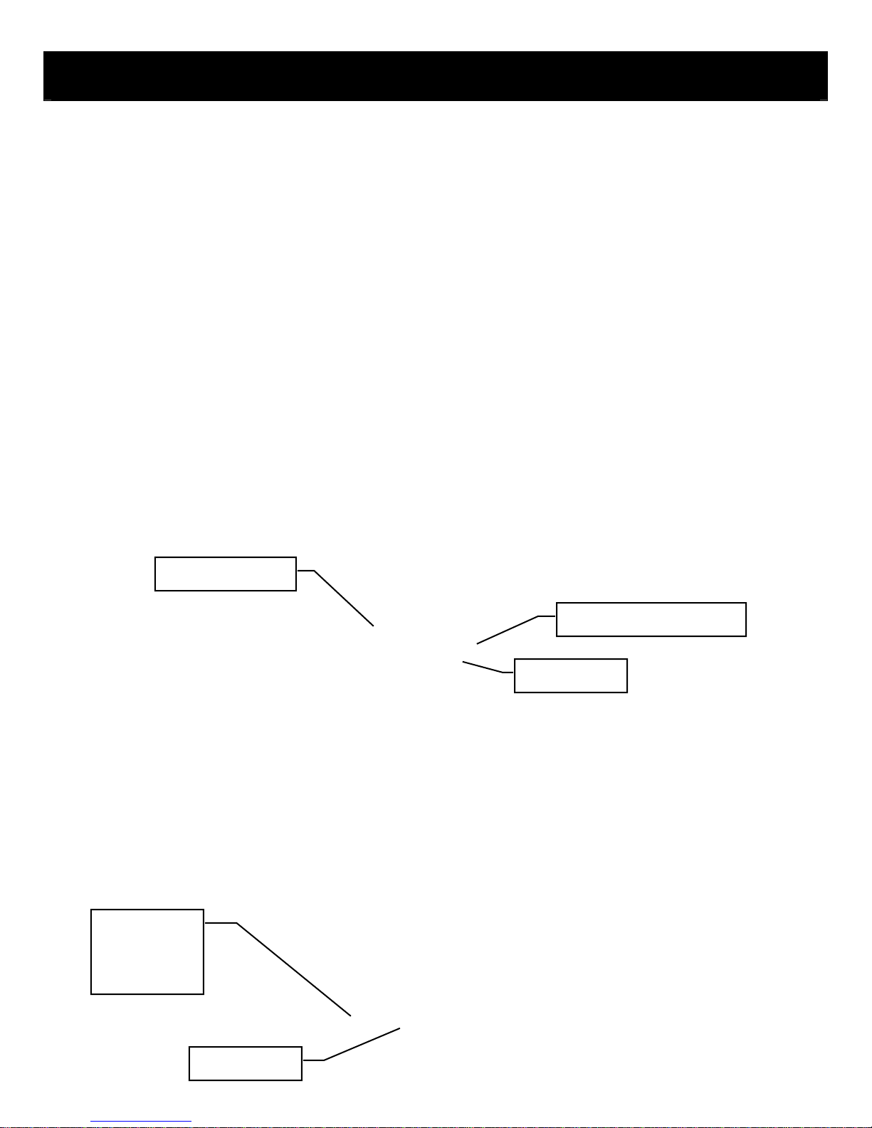
33-MVHS Heat Shield for Models ZDV6000, ZDV3320, MQRB3328
11
The MVHS is a heat shield designed to protect electrical components inside the above units when a Z33FK Fan
Kit and Z33CVCK Kit are installed. See below for installation instructions.
Also Included:
[2] DT Screws
Step 1-Gain access to left side of fireplace. For appliances already
33-MVHS
installed where the lower front panel is not removable (i.e. covered
with masonry, etc.), see other side of this page.
Pilot Connections
(MQRB3328)
Gasline
Step 2- Bend down mount tabs. Slide 33-MVHS Heat Shield into place against side of fireplace. Must be placed
BENEATH pilot connections for MQRB3328 and ABOVE gasline.
Pilot Connections
(MQRB3328)
Step3- Using EXISTING HOLES in the outside of the unit, secure 33-MVHS with the [2] DT screws Provided.
Bend down supports on 33-MVHS.
Gasline
33-MVHS Heat Shield for Models ZDV6000, ZDV3320, MQRB3328
g
12
For Appliances Already Installed With Z33CVCK & Z33FK- Lower Panel Fixed
1. If the lower panel of the CVCK is not removable, the 33MVHS can be inserted through the opening at the front of the
CVCK.
2. Bend down Mount Tabs and slide into place. For MQRB3328, be extremely careful not to damage the pilot tubing
above the 33-MVHS.
Insert 33-MVHS
Throu
3. Fold support legs down. When in place, secure to outer side of unit with at least one screw. It is important that the
33-MVHS is against the outer side of the fireplace so that no air can draft down onto the electrical components when
the fan is on.
h Opening
Pilot Tubing Will Be Above
33-MVHS For MQRB3328
Gas Line Will Be
Below 33-MVHS
33-MVHS Must
Be Against Side
and Fastened
By At Least One
Screw
Support Legs
Folded Down

How To Install Clean View Kit (Cvck)
/
13
For ZDV3318/ZDV3622/ZDV6000/ZDV3320/MQRB3328/MQZDV3318/MQZDV3622
WARNING: Failure to position the parts in accordance with these diagrams or failure to use only parts
specifically approved with this appliance may result in property damage or personal injury.
NOTE: When using the Clean View Kit (CVCK) and installing optional electrical components (i.e. Remote
Controls, variable speed control, and or fan modules) locate them in the Clean View access area, unless
other shielding devices like our IPI Component box is used.
For ZDV6000
ZDV3320 / MQRB3328, the 33-MDVHS Heat Shield must be used.
CAUTION: When using CVCK DO NOT INSTALL a Louver assembly.
1. Install optional fan kit (see Fan Instruction).
2. Fold two standoffs up into position and mount with supplied screws. (FIG 1) For ZDV6000/ ZDV3320/ MQRB3328
models use the larger (8”) standoffs. On the ZDV3318 unit, remove the large 8” standoffs.
3. Hang CVCK on top of fireplace retainer tabs and rotate down into position. (FIG 2)
4. Using the screws provided, fasten the non-combustible header onto the top of the CVCK assembly.
5. Using four [4] supplied #6 screws, fasten CVCK kit to the inside frame of unit.
6. Using ten [10] supplied screws, install the top shield into the CVCK.
7. Kit is supplied with 2 valve extension knobs. Align the notches and slide the extensions onto valve knobs.
8. DO NOT brick or tile beyond the inside area of the CVCK kit to allow for removal of door.
NOTE: ADDITIONAL ACCESS FOR GASLINE INSTALLATION AND FAN ELECTRICAL INSTALLATION! When CVCK is installed
in framing, remove the four [4] screws from the bottom panel. Once screws are removed, bottom panel can be removed to access
gas valve and fan system.
CLEARANCES - ZDV3320/6000/MQRB3328 - Mantels & Surrounds
WARNING: Combustible objects must not be placed on a non-combustible mantel unless the non-
combustible mantel meets the minimum height and width requirements for a combustible mantel.
14
ZDV3320/6000/MQRB3328
- Clearance to Combustibles
Clearance to Combustibles
Back (from Standoffs) 0 inches/0 mm
Side (from standoffs) 0 inches/0 mm
Floor 0 inches/0 mm
Ceiling (from bottom of fireplace) 60 inches/150 cm
Top (from standoffs) 0 inches/0 mm
Louvered Unit
Top of 90 degree bend in Minimum
Enclosure of 43 to 60 inches 6 inches/152.5 mm / All Vent Systems
Enclosure over 60 inches 2 1/2 inches/38mm/All Vent Systems
CVCK Unit (non louvered)
Top of 90 degree bend in Minimum
Enclosure of 45 inches to 55 inches 9 inches/228.6 mm / All Vent Systems
Enclosure over 55 inches 2 1/2 inches/38mm All vent Systems
Top of Horizontal Pipe 1 1/2 inches/38 mm / All Vent Systems
Side & Bottom of Horizontal Pipe 1 inch/25.5mm / All Vent Systems
Vertical Vent Pipe 1 inch/25.5mm / Kingsman Vent Systems
Vertical Vent Pipe 1 1/4 inch/32mm / Simpson/AmeriVent/Selkirk Direct Temp
Systems
(NOTE -Floor) if installing the
appliance directly on
carpeting or other combustible
materials other than wood
flooring, the appliance shall be
installed on a metal or wood
panel, the full width and depth
of the appliance. Carpet may
extend 1 inch above the floor
of appliance.
For units with CVCK (Clear
View Circulating Kit) see
framing with CVCK to
establish floor heights
15
Mantels
Depending on the depth of the fireplace mantel, it may be installed
higher or lower from the top of the fireplace opening. See
drawings for proper installation height of your combustible mantel.
Non-combustible mantels may be installed at any height above the
fireplace opening.
Non combustible materials such as brick, tile, etc. can extend up
to or over the front face of the fireplace (NO PORTION OF GRILL
AREA OR DOOR AREAS CAN BE COVERED).
Combustible material can extend flush to unit up to the top, bottom
and sides of fireplace to stand-offs.
For COMBUSTIBLE materials extending in front of fireplace
consult (Mantel and Mantel Leg Drawings).
Note when using SIMPSON DURAVENT ADAPTER (ZDVDFA)
the fireplace clearances from the back standoff is one inch,
thus increasing the framing depth to 15”.
If slim line brass surround is used, brick, tiles or other NONCOMBUSTIBLE materials may extend past the front of unit
giving a recessed appearance. For COMBUSTIBLE materials
extending in front of fireplace consult (Mantel and Mantel Leg
Drawings).
If wide brass surround is used finish materials must be flush
with front of unit.
Note: When using paint or lacquer to finish the mantel, such
paint or lacquer must be heat resistant (250˚F) to prevent
discoloration.
WARNING: Combustible objects must not be
placed on a non-combustible mantle unless the noncombustible mantle meets the minimum height and
width requirements for a combustible mantle.
Side Walls
13
14
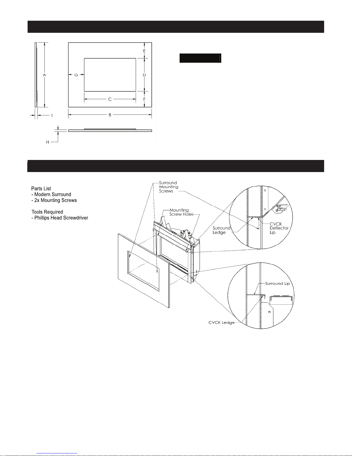
MQ33SW Wall Mount Surround Dimensions
MQ33SWF
A
35-5/16”
B
45-13/16”
C
28-3/8”
D
17-13/16”
E
8-3/4”
F
8-3/4”
G
8-3/4”
H
1”
I
1-3/16”
Installation of MQSW Wall Mount Surround
1. Set Surround Lip on CVCK Ledge and ensure that it is securely in place.
2. Swing the upper portion of the Surround so that the Surround Ledge is resting on top of the
CVCK Deflector Lip.
3. Align the Mounting Screw Holes and fasten the Surround in place with the supplied screws.
4. Attach optional decorative bands as desire.
5. To remove, simply reverse these steps.
Installation of MQ33SW Wall Mount Surround
16
15
g
g
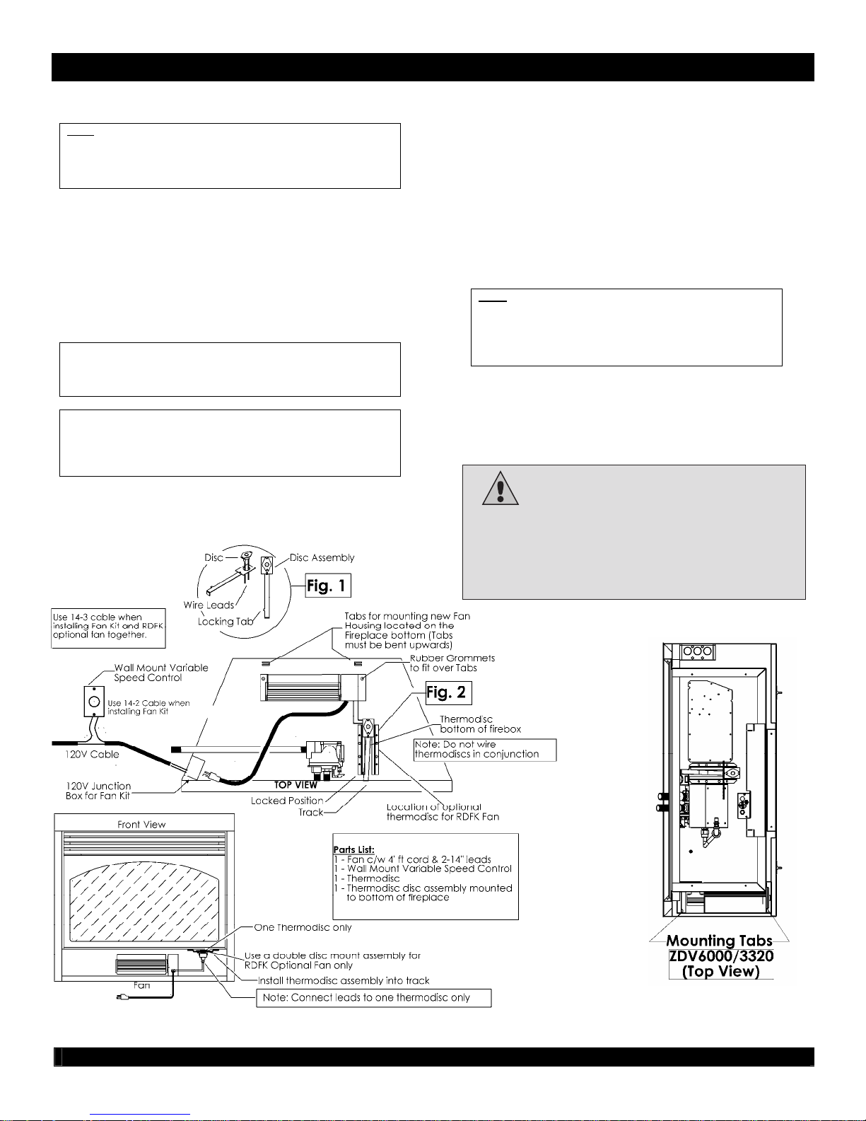
Fan Kit Installation
WARNING:
Electrical Grounding Instructions.
This appliance is equipped with a three-pronged
(grounding) plug for your protection against shock
hazard and should be plugged directly into a properly
grounded three-prong receptacle. Do not cut or remove
the grounding prong from this plug.
17
Fan installation Instructions for ZDV6000/3320/3318/3318MQ
with or without CVCK (Clean View Circulating Kit).
Note:
Install Fan Kit Before Installing optional CVCK (Clean
View Circulating Kit).
If CVCK has been installed into framing additional access is
provided by removing screws from bottom panel of CVCK. See
Installing Clean View Kit (CVCK).
1. Slide fan housing into unit and place over 2 Fan Retainer Tabs. Tabs
are pre punched and bent up (*Note: on 6000/3320 units, these
Tabs are located on the right side of the unit). Rubber grommets
at the base of the fan should fit snugly over the tabs.
2. For Fan Disc Installation these units have been installed with a sliding
track system. Install the Thermodisc provided with the Fan Kit. Place
Thermodisc into sliding assembly (Fig.1), and attach 2 leads exiting
right side of the fan housing into thermodisc. Now slide disc assembly
into thermodisc track (Fig.2). Place swivel handle of disc assembly
on track to lock into position. To service disc simply pull swivel handle
slide towards you while rotating handle to access disc.
Caution: Label all wires prior to disconnection when
servicing controls. Wiring errors can cause improper and
dangerous operation.
Verify proper operation after servicing.
Parts List:
1ea. Fan comes with 4ft cord. Two 14” leads (female ends)
1ea. Variable speed control (wall mount type)
1ea. Thermodisc
1 Thermodisc mount assembly
3. Wire Junction Box and wall mounted variable speed control to
120v. Install a duplex outlet to junction box and plug fan into
outlet.
4. Turn the wall switch on (clockwise). Turn fireplace on. Once the
5. To set the minimum fan speed, remove the variable switch from
Electrical Services
All optional Fan Kits are equipped with a 120V, 60Hz, .4amp blower.
Note: All electric connections are to be made in accordance with
CSA Standard C22.1 – Canadian Electrical Code part I or with the
National Electrical Code, ANSI/NFPA 70 (latest edition) and /or in
accordance with local codes.
sensor in the unit reaches operating temperature (approximately
10 to 15 minutes) the fan will turn on. The fan can be switched
off if desired by turning the wall switch fully counter clockwise.
the wall mount. Turn the variable speed wall controller to its
minimum setting (fully counterclockwise). Use the set screw on
the side of the variable speed controller to increase or decrease
the minimum fan speed (lowering the minimum fan speed will
decrease sound level created by fan).
Reinstall switch into wall mount and cover with face plate.
Note:
To service fan with CVCK Kit installed see Removing
Burner System in manual. If CVCK is finished with a MQSW
Wall Surround the MQSW may be removed by removing the
4 attachment screws and removing the MQSW
allowing access into the bottom of the fireplace to service
blower.
Warning:
Electrical Grounding Instructions. This
CAUTION: DO NOT ATTACH 120V FAN ASSEMBLY TO MILLIVOLT GAS VALVE SYSTEM
appliance is equipped with a three-pronged (grounding)
plug for your protection against shock hazard and
should be plugged directly into a properly grounded
three-prong receptacle. Do not cut or remove the
grounding prong from this plug.

Split Receptacle- Fan Speed Control Outside of Fireplace
18
If you plan to locate the variable speed control switch for the fan outside of the fireplace and you require a constant source
of AC power inside the unit for another accessory such as lights or an IPI valve system, follow one of the procedures
below.
WARNING WARNING WARNING
A qualified electrician must connect
electrical wiring to junction outlet for
built-in installation.
Follow all codes.
Caution: Electrical installation to be done by a qualified installer. All wires must be connected and grounded in accordance with
CSA Standard C22.1- Canadian Electrical Code part 1 or with the National Electrical Code, ANSI /NFPA 70 (latest edition) and /or in
accordance with local codes.
Switch Controlled Split Receptacle With Switch At START Of Cable Run
Electrical Grounding Instructions –
This appliance is equipped with a
three – pronged (grounding) plug for
your protection against shock hazard
and should be plugged directly into a
properly grounded three-prong
receptacle.
Label all wires prior to disconnection
when servicing controls. Wiring errors
can cause improper and dangerous
operation. Verify proper operation and
servicing.
Switch Controlled Split Receptacle With Switch At END Of Cable Run
 Loading...