

Kingsman ZCV42NE, ZCV42LP, ZCV42LPE, ZCV39NH, ZCV39NHE Installation Instructions Manual
...
Model Numbers:
ZCV39N, ZCV39NE, ZCV39LP, ZCV39LPE
ZCV42N, ZCV42NE, ZCV42LP, ZCV42LPE
Certified to:
ANSI Z21.50-2014 • CSA 2.22-2014
ZERO CLEARANCE VENTED GAS FIREPLACE
Model Numbers:
ZCV39NH, ZCV39NHE, ZCV39LPH, ZCV39LPHE
ZCV42NH, ZCV42NHE, ZCV42LPH, ZCV42LPHE
Certified to:
ANSI Z21.88-2014 • CSA 2.33-2014
ZERO CLEARANCE VENTED GAS FIREPLACE HEATER
-Do not store or use gasoline or other flammable vapors and liquids in the vicinity of this or any other
appliance.
-WHAT TO DO IF YOU SMELL GAS
Do not try to light any appliance.
Do not touch any electrical switch; do not use any phone in your building.
Immediately call your gas supplier from a neighbor’s phone. Follow the gas supplier’s instructions.
If you cannot reach your gas supplier, call the fire department
-Installation and service must be performed by a qualified installer, service agency or the gas
supplier.
Installation Instructions
This appliance may be installed in an aftermarket, permanently located, manufactured home (USA
only) or mobile home, where not prohibited by local codes.
This appliance is only for use with the type of gas indicated on the rating plate. This appliance is not
convertible for use with other gases, unless a certified kit is used.
INSTALLER: Leave this manual with the appliance.
CONSUMER: Retain this manual for future reference.
A Division of R-Co. Inc.
2340 Logan Ave.
Winnipeg, Manitoba Canada
R2R 2V3 Ph.: (204) 632-1962
Printed in Canada October 5, 2015
Part# 39ZCV-MAN14
For Propane Horizontal
installations the venting must
be an additional one foot
above the minimum vertical
rise off the flue before going
horizontal.
WARNING: If the information in these instructions are not followed exactly, a fire or explosion may
result causing property damage, personal injury or loss of life.
BENTLEY

Table of Contents
INFORMATION
Table of Contents…………………………………………………………….................................................................
2-3
Glass Safety / Termination Cap Safety- All Units………………………………………………………………………..
4
Warnings, Installations, and Operations…………………………………..................................................................
5-6
Pre-installation Questions and Answers…………………………………..................................................................
7
Operating Instructions……………………………………………………….................................................................
7
Recommendations for Finishing of Clean View Installations..................................................................................
8
Mobile Home/Manufactured Housing Installation…………………….......................................................................
9
Nailing Tab Guide...................................................................................................................................................
10
ZCV39 / ZCV42 Framing Your Gas Fireplace…………………………………………………………………………....
11
ZCV39 INSTALLATION
Locating Your Appliance / Fireplace Dimensions………………………………………………………………………..
12
Framing Dimensions………………………………………………………………………………………………………...
13
Clearance to Combustibles…………………………………………………………………………………………………
14
Facing Requirements……………………………………………………………………………………………………….
15
ZCV42 INSTALLATION
Locating Your Appliance / Fireplace Dimensions………………………………………………………………………..
16
Framing Dimensions………………………………………………………………………………………………………...
17
Clearance to Combustibles………………………………………………………………………………………………...
18
Facing Requirements……………………………………………………………………………………………………….
19
BASIC FINISHING: ZCV39 & ZCV42
Basic Finishing 1: With Screen Only…………………………………………………………………………………….
20
Basic Finishing 2: With S1 or S1PF Surround………………………………………………………………………….
21-22
Basic Finishing 3: Concrete Board Behind S2PF Surround (3/4” Maximum Total Thickness)……………………
23
Basic Finishing 4: Stone or Brick Around S2PF Surround……………………………………………………………
24
Basic Finishing 5: Tile Border Behind S2PF Surround (3/4” Maximum Total Thickness)…………………………
25
Basic Finishing 6: With MQZCV42DD & Stone, Brick, or Tile Boarder……………………………………………...
26-27
ZCV-TLK Optional Tile Lip Kit …………………………………………………………………………...........................
28
39ZCV Mantel Clearances………………………………………………………………………………………………….
29
42ZCV Mantel Clearances………………………………………………………………………………………………….
30
ACCESSORIES
ZCV39CSS / ZCV42CSS Child Safety Screen Installation…………………………………………………………......
31
ZCV39 / ZCV42 Surround Installations…………………………………………………………………………………...
32
MQZCV39DD / MQZCV42DD Designer Door Installations……………………………………………………………..
33
ZCV39 / ZCV42 51UHS Box / Component Locations…………………………………………………………………...
34
ZCV39 / ZCV42 Z46FK Fan Kit Installation………………………………………………………………………………
35
Fan Speed Control Outside of Fireplace………………………………………………………………………………….
36
ZCV39PL / ZCV42PL Porcelain Liner Installation……………………………………………………………………….
37
ZCV39RL / ZCV42RL Brick Liner Installation…………………………………………………………………………….
38
ZCV39GT / ZCV42GT Glass Tray Setup…………………………………………………………………………………
39
ULK2 Universal Light Kit……………………………………………………………………………………………………
40-41
Log F3 Setup………………………………………………………………………………………………………………...
42
RBCB1 Cannonballs………………………………………………………………………………………………………..
43
MQ Dealer Accessories for ZCV39 / ZCV42……………………………………………………………………………..
44-46
MQ Log F9 Setup…………………………………………………………………………………………………………....
47-48
GENERAL INSTALLATION, USE, AND MAINTENANCE
ZCV39 & ZCV42 Door Installation………………………………………………………………………………………...
49
Door and Glass Information………………………………………………………………………………………………..
50
Gas Line Installation………………………………………………………………………………………………………...
51
Millivolt System, Lighting, and Burner Control…………………………………………………………………………...
52
Troubleshooting the Gas Control System………………………………………………………………………………...
53
2

Burner System Maintenance……………………………………………………………………………………………….
54
Conversion Kit Instructions – PART A…………………………………………………………………………………….
55
Gas Conversion Kit For Top Convertible Pilot PART B…………………………………………………………………
56
Gas Conversion for Modulator – PART C………………………………………………………………………………...
57
Burner Removal / Burner System Removal / Installation……………………………………………………………….
58
IPI SECTION
IPI Electronic Ignition System……………………………………………………………………………………………...
59
Remote Control Operation………………………………………………………………………………………………….
60
IPI Electronic Ignition Parts List – Standard System…………………………………………………………………….
61
Configuration 1: Basic Manual Hi / Lo and manual Off………………………………………………………………….
62
Configuration 2: Remote On / Off and manual Hi / Lo…………………………………………………………………..
63
Operating the Receiver Without Batteries For GT / EGT / GTM / EGTM Remote Controls………………………...
64
Configuration 3: Remote ON/OFF, Variable HI/LO, and Fan…………………………………………………………..
65
Electronic Ignition Lighting Instructions…………………………………………………………………………………...
66
VENTING
Vent Termination…………………………………………………………………………………………………………….
67
General Vent Installation…………………………………………………………………………………………………...
68
Installation of Side Wall Venting…………………………………………………………………………………………...
68
Venting Routes And Components…………………………………………………………………………………………
69
Horizontal Venting Table…………………………………………………………………………………………………...
69
Z47ST24 / Z47ST36 Horizontal Snorkel Terminations………………………………………………………………….
70
Venting Straight Up Through Roof………………………………………………………………………………………...
71-72
Approved for Power Vent PVH58………………………………………………………………………………………….
73
PARTS LISTS
PVH58 Parts List…………………………………………………………………………………………………………….
74
ZCV39 Parts List…………………………………………………………………………………………………………….
75-76
ZCV42 Parts List…………………………………………………………………………………………………………….
77-78
WARRANTY
Limited Lifetime Warranty………………………………………………………………………………………………......
79
3
-Glass Safety- All Units
-Termination Cap Safety- All Units
WARNING:
WHEN THE HORIZONTAL VENT TERMINATION IS ACCESSIBLE
A CERTIFIED GUARD (SAFETY CAGE) SHALL BE INSTALLED.
4
IT IS THE RESPONSIBILITY OF THE
HOME OWNER TO ENSURE THAT
NO ONE TOUCHES A HOT
APPLIANCE.
If the barrier becomes damaged, the barrier
shall be replaced with the manufacturer’s
barrier for this appliance.
Any safety screen, guard, or barrier removed for
servicing the appliance, must be replaced prior
to operating the appliance.
Children and adults should be alerted to the
hazards of the high surface temperatures of this
appliance and should stay away to avoid
burns or ignition of clothing.
Do not clean when the glass is hot.
Young children should be carefully supervised when they are in the same room as the appliance. Toddlers,
young children and others may be susceptible to accidental contact burns.
A physical barrier is recommended if there are at risk individuals in the house. To restrict access to a fireplace or
stove, install an adjustable safety gate to keep toddlers, young children and other at risk individuals out of the
room and away from hot surfaces.
Do not leave the fireplace remote control where it is accessible to children.
SAFETY CAGES ARE AVAILABLE FOR ALL HORIZONTAL VENT TERMINATIONS.
CHECK WITH YOUR DEALER.
TERMINATION CAP IS HOT! Do not place flammable materials on or within 24 inches of termination caps.
It is imperative that the vent termination be located observing the minimum clearances as shown in manual.
There must not be any obstruction such as bushes, garden sheds, fences, decks or utility buildings within 24"
from the front of the termination plate.
Do not locate termination where excessive snow or ice build-up may occur. Be sure to check vent termination
area after snow falls and clear to prevent accidental blockage of venting system. When using snow blowers,
make sure snow is not directed towards vent termination area.
Venting terminal shall not be recessed into a wall or siding.
Warnings, Installations and Operations
WARNING
FOR SAFE INSTALLATION AND OPERATION OF YOUR GAS FIREPLACE PLEASE NOTE THE FOLLOWING:
1. Do not clean when the glass is hot.
2. Do not use abrasive cleaners.
3. Using a substitute glass will void all product warranties.
4. For safe operation, glass doors must be closed.
5. When purging the gas line, the glass front must be removed.
6. Do not strike or abuse glass. Take care to avoid breakage.
7. Do not alter gas orifice.
8. No substitute materials may be used other than factory
supplied components.
9. This appliance gives off high temperatures and should be
located out of heavy traffic areas and away from furniture and
draperies.
10. Children and adults should be alerted to the hazards of the high
surface temperatures of this appliance and should stay away to avoid burns or ignition of clothing.
11. Young children should be carefully supervised when they are in the same room as the appliance. Toddlers, young children
and others may be susceptible to accidental contact burns. A physical barrier is recommended if there are at risk individuals
in the house. To restrict access to a fireplace or stove, install an adjustable safety gate to keep toddlers, young children and
other at risk individuals out of the room and away from hot surfaces.
12. Under no circumstances should any solid fuels (wood, paper) be used in this appliance.
13. Under no circumstances should this appliance be modified. Any parts that have to be removed for servicing should be
replaced prior to operating this appliance.
14. Any safety screen, guard, or barrier removed for servicing an appliance must be replaced prior to operating the appliance.
15. Installation and repair should be done by a qualified service person. The appliance should be inspected before use and at
least annually by a professional service person. More frequent cleaning may be required due to excessive lint from
carpeting, bedding material, et cetera. It is imperative that control compartments, burners and circulating air passageways
of the appliance be kept clean. Make sure that the gas valve and pilot light are turned off before you attempt to clean this
unit.
16. Clothing or other flammable material should not be placed on or near the appliance. This appliance should not be used as a
drying rack for clothing nor should Christmas stockings or decorations be hung from it.
17. Do not use this heater if any part has been under water. Immediately call a qualified service technician to inspect the heater
and to replace any part of the control system and any gas control which has been under water.
18. Do not operate appliance unless completely installed as per installation instructions.
19. Failure to position the parts in accordance with these diagrams or failure to use only parts specifically approved with this
appliance may result in property damage or personal injury.
20. WARNING: Do not operate appliance with the glass front removed, cracked or broken. Replacement of the glass
should be done by a licensed or qualified service person.
21. The appliance area must be kept clear and free from combustible materials, gasoline, and other flammable vapors and
liquids.
22. The front of the fireplace gives off high temperatures that could ignite combustible material which is kept close to the front of
the unit.
23. Ensure that power to the Fireplace is turned off before servicing.
24. Do not operate this Fireplace without the glass front or with a broken glass.
25. Improper installation, adjustment, alteration, service or maintenance can cause injury or property damage. Refer to the
owner’s information manual provided with this appliance. For assistance or additional information consult a qualified
installer, service agency, or the gas supplier.
26. Operation of this appliance when not connected to a properly installed and maintained venting system or tampering with the
blocked vent shutoff system can result in carbon monoxide (CO) poisoning and possible death.
27. This appliance is equipped with a three-prong (grounding) plug for your protection against shock hazard and should be
plugged directly into a properly grounded three-prong receptacle. Do not cut or remove the grounding prong from this plug.
5
Installation Regulations
This gas appliance must be installed by a qualified installer in accordance with local building codes, or in the absence of local codes, with the current
CAN/CSA-B149.1 or .2 Installation Code (in Canada) or the current National Fuel Gas Code Z223.1- NFPA 54 when installed in the United States.
This appliance, when installed, must be electrically connected and grounded in accordance with local codes, or in the absence of local codes, with the
current CSA C22.1 Canadian Electrical Code or with the National Electrical Code; ANSI/NFPA 70 when installed in the United States.
In the U.S.A. Thermostats are not permitted for Vented Gas Fireplaces (ANSI Z21.50b-Decorative).

Gas fired appliances may be used only for supplemental heat and/or decorative purposes and under no circumstances shall they
NOTE: It is recommended that a Carbon Monoxide (CO) Detector be installed in or near bedrooms and on all levels of your home.
Place a detector about 15ft [4.5m] outside the room that houses your gas appliance.
Certified for installation in a bedroom or bed/sitting room. In Canada must be installed with listed millivolt thermostat.
In the U.S.A. Thermostats are not permitted for Vented Gas Fireplaces (ANSI Z21.50b-Decorative).
In USA see local codes.
6
provide a primary heat source.
This appliance must not be connected to a chimney flue serving a separate solid-fuel burning appliance.
Operations and Maintenance Instructions
For safe installation and operation note the following:
• Venting systems should be periodically examined by a qualified agency.
• The flow of combustion and ventilation air must not be obstructed.
• The Burner/Log Assembly has been engineered and permanently adjusted for proper flame control.
• Periodically remove the logs from the grate assembly and vacuum any loose particles from the grate and burner areas. See Log
Placement page to remove logs. Vacuum burner parts and replace logs.
• Never use your gas fireplace as a cooking device.
• Label all wires prior to disconnection when servicing controls. Wiring errors can cause improper and dangerous operation. Verify
proper operation after servicing.
Installation Requirements for the Commonwealth of Massachusetts
In the Commonwealth of Massachusetts, the installer or service agent shall be a plumber or gas fitter licensed by the Commonwealth.
When installed in the Commonwealth of Massachusetts or where applicable codes; the unit shall be installed with a CO detector per the
requirements listed below.
1. For direct-vent appliances, mechanical-vent heating appliances or domestic hot water equipment, where the bottom of the vent
terminal and the air intake is installed below four feet above grade the following requirements must be satisfied:
A. If there is not one already present, on each floor level where there are bedroom(s), a carbon monoxide detector and alarm
shall be placed in the living area outside the bedroom(s). The carbon monoxide detector shall comply with NFPA 720.
B. A carbon monoxide detector shall be located in the room that houses the appliance or equipment and shall:
Be powered by the same electrical circuit as the appliance or equipment such that only one service switch services
both the appliance and the carbon monoxide detector;
Have battery back-up power;
Meet ANSI./UL 2034 Standards and comply with NFPA 720; and
Have been approved and listed by a Nationally Recognized Testing Laboratory as recognized under 527 CMR.
C. A Product-approved vent terminal must be used, and if applicable, a Product-approved air intake must be used.
Installation shall be in strict compliance with the manufacturer’s instructions. A copy of the installation instructions shall
remain with the appliance or equipment at the completion of the installation.
D. A metal or plastic identification plate shall be mounted at the exterior of the building, four feet directly above the location of
vent terminal. The plate shall be of sufficient size to be easily read from a distance of eight feet away, and read “Gas Vent
Directly Below”.
2. For direct-vent appliances, mechanical-vent heating appliances or domestic hot water equipment where the bottom of the vent
terminal and the air intake is installed above four feet above grade the following requirements must be satisfied:
A. If there is not one already present, on each floor level where there are bedroom(s), a carbon monoxide detector and alarm
shall be placed in the living area outside the bedroom(s). The carbon monoxide detector shall comply with NFPA 720.
B. A carbon monoxide detector shall:
Be located in the room that houses the appliance or equipment;
Be either hard-wired or battery powered or both; and
Shall comply with NFPA 720.
A Product-approved vent terminal must be used, and if applicable, a Product-approved air intake must be used. Installation shall be in
strict compliance with the manufacturer instructions. A copy of the installation instructions shall remain with the appliance or equipment
at the completion of the installation.
For the state of Massachusetts a T-handle gas shut-off valve must be used on a gas appliance. This T-handle gas shut-off valve must be listed and
approved by the state of Massachusetts. This is in reference to the state of Massachusetts state code CMR238.

Pre-installation Questions and Answers
Operating Instructions
1. Be sure to read and understand all the instructions in this manual before operation of appliance.
2. Ensure all wiring is correct and properly enclosed to prevent possible shock.
3. Check for gas leaks.
4. Make sure the glass door is properly installed before operation. Never operate the appliance with the glass door
removed.
5. Make sure venting and termination cap are installed and unobstructed.
6. If brick or porcelain liners are used, ensure they are installed.
7. Verify that the pilot can be seen when lighting the appliance. If not, the log or rock placement is incorrect.
8. If the unit is turned off, you must wait a minimum of 60 seconds before re-lighting it.
7
About curing of the paint
Your stove or fireplace has been painted with the highest quality silicone stove paint. This paint dries quickly in 15-20
minutes when first applied at the factory. However, due to the high temperature silicone components, the paint will cure
when heat is applied to the appliance as it is first used. The following information applies to the curing process to get the
paint fully hard and durable.
Fire the appliance four successive times for 10 minutes each firing and a 5 minute cool down between each. Be aware
during log and firebox paint curing that a white deposit may be developing on the inside of the glass doors. It is important
to remove this white deposit from the glass doors using a fireplace glass cleaner.
Babies, small children, pregnant women and pets should leave the area during the cure phase.
Ventilate well, open doors and windows.
Do not touch during curing.
Why does my fireplace or stove give off odour?
It is normal for your fireplace to give off some odor at first. This is due to the curing of the paint, adhesives, silicones and
any undetected oil from the manufacturing process as well as the finishing materials used with the installations (e.g.
marble, tile and the adhesives used to adhere this product to the walls can react with heat and cause odours).
It is recommended that you burn your gas fireplace or stove for a minimum of four hours at a time with the fan off (if a fan
is present) after the curing of the paint has been completed. These odours can last upward to 40 hours of burn time; keep
burning at a minimum of four hours per use until odours dissipate.
Noise coming from the fireplace?
Noise is caused by the expansion and contraction of metal as the appliance heats up and cools down. This is normal and
is similar to the sounds produced by a furnace or heating duct. This noise does not affect the operation or longevity of
your fireplace.
It is also normal for the fan to make some noise when it comes on. This noise can be reduced somewhat by turning down
the speed of the fan with the variable speed control. Be aware, however, that this will reduce the volume of heated air
circulated into the room by the fan.
Note to the Installer:
Be sure appliance is working properly and its operation (including remote control operation, if included) is fully explained
to and understood by the customer.
Recommendations for Finishing of Clean View Linear Products
8
When finishing the wall around the fireplace, it is critical that the wall covering be fastened properly. It is acceptable to
pre-drill holes and use self-tapping screws which may be used to fasten a backer for tile, marble, etc. Screws being
installed through non-combustible board should be self-tapping type with a maximum length of 2 inches. Wall covering
fasteners, such as screws or nails, are not permitted in some locations. Do not drill or install longer screws which may
penetrate into the lower cover panel area as this may damage internal components.
Only non-combustible materials may be used over the face of the appliance.
We recommend that DUROCK (non-combustible material) be tied in to the entire perimeter of the fireplace for durability.
Finishing Recommendations (Obtained from professional construction contractors and finishers):
Frame unit with metal studs (minimum 20 gauge).Wooden studs may be used, but may cause drywall screws to pop
or pull due to wood studs drying out.
Minimum of 1/2” DUROCK cement board (this non-combustible panel is ULC listed as a wall shield/floor protector) and
fasten to the entire perimeter framing.
Use fiberglass (mesh) tape for all joints in area of the fireplace.
Use Yellow joint mud (contains high amounts of glue) – two coats, finishing with one coat of green topping mud, sand
and prep for painting.
If not using a surround, a metal “L” Trim may be used to finish perimeter of DUROCK.
Refer to the following website for more information on using DUROCK Cement Board: www.cgcinc.com
OTHER NOTES:
-A full single sheet of non-combustible board (no joints) above the unit is recommended if possible.
-It is preferred to attach the non-combustible board to framing only and not directly to the unit to allow for expansion and
contraction during normal operation.
-Lighter colored painted surfaces may discolor due to heat exposure.
Mobile Home/Manufactured Housing Installation
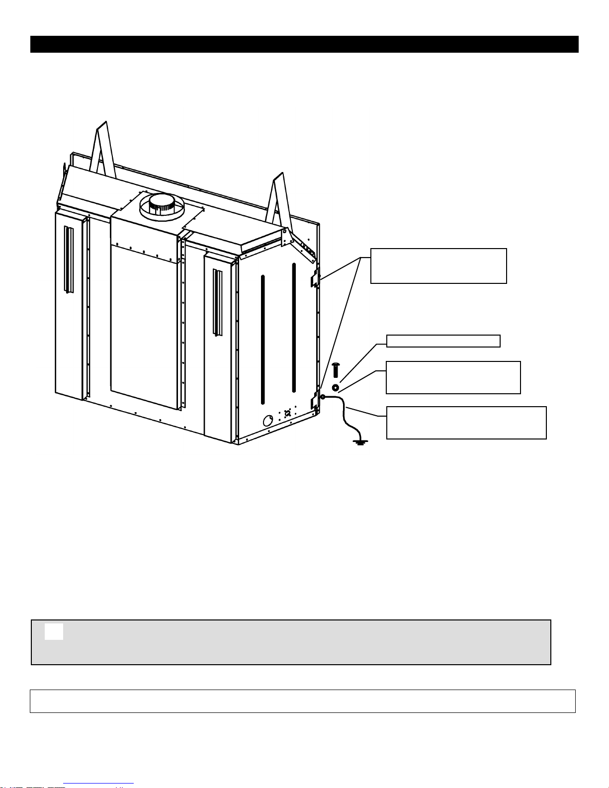
Warning: Do not compromise the structural integrity of the manufactured home wall, floor
or ceiling, during installation of appliance or venting.
Appliance Must Be Secured To
Structure Using Supplied Nailing
Tabs And Or Fastened To Floor.
Use Existing Hole Or Remove
Existing Screw To Mount Ground
Wire (Nailing Tab Screw).
Serrated Or Star Washer
Ground Wire From Appliance To Steel
Chassis Of Mobile Home. USE 8GA
COPPER WIRE.
9
This Direct Vent System Appliance must be installed in accordance with the manufacturer’s installation instructions and the
Manufactured Home Construction and Safety Standard Title 24 CFR, Part 3280, or the current Standard for Fire Safety Criteria for
Manufactured Home Installations, Sites, and Communities ANSI/NFPA 501A, and with CAN/CSA Z240 MH Mobile Home Standard in
Canada.
THE VENTED GAS FIREPLACE HEATERS (ANSI Z21.88-2009) IN THIS MANUAL MAY BE INSTALLED IN MANUFACTURED
(MOBILE) HOMES AFTER FIRST SALE IN THE USA.
THE VENTED GAS FIREPLACE HEATERS (ANSI Z21.88-2009) IN THIS MANUAL MAY BE INSTALLED IN MANUFACTURED
(MOBILE) HOMES IN CANADA.
Please follow the current ANSI/NFPA 70 National Electrical Code in the USA and CAN/CSA C22.1 Canadian National
Electrical Code in Canada.
An appliance must be grounded to the steel chassis of the home with 8 ga. copper wire using a serrated or star washer to
penetrate paint or protective coating to insure grounding.
Use carriage bolt at the attachment point (see diagram above) to secure the appliance to the floor.
For required venting components see venting installation in appropriate section of this manual.
Certified for installation in a bedroom or bed/sitting room. In Canada must be installed with listed millivolt thermostat. In USA see local
codes.
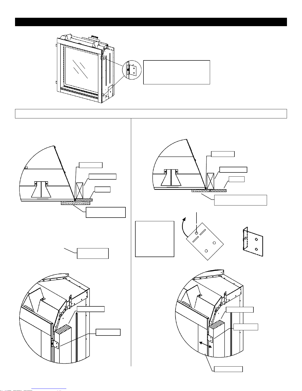
ZCV39 / ZCV42 Framing- Nailing Tab Guide
These Nailing Tabs can be used in two ways:
1/2” Drywall Flush with Face of Fireplace –
Fireplace and Combustible Wall to be covered
with a surround or Non-Combustible Materials
(e.g. Stone around Fireplace).
Framing Flush with Face of Fireplace -Fireplace to be covered
with Non-Combustibles (e.g. Concrete Board) for Flat Wall
appearance.
[Qty]2 Nailing Tabs are
located on each side of the
front frame.
Nailing Tab
Framing Stud
Drywall
Non-Combustible
Material (eg. Stone)
Nailing Tab
Framing Mount
Nailing Tab
Nailing Tab
Framing Stud
Drywall
Non-Combustible Material
(eg. Concrete Board)
Nailing Tabs
Must Be
Rotated 180°
And Folded
Back Onto
Framing Stud.
Nailing Tab
Framing Stud
Framing Stud
Flush Surface
10
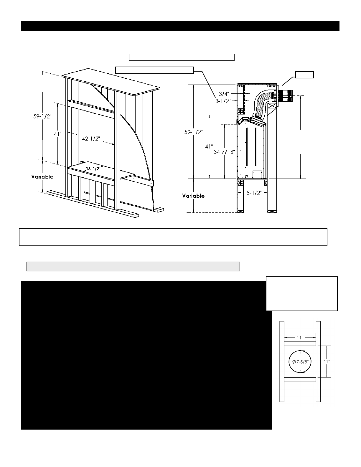
ZCV39 / ZCV42 Framing Your Gas Fireplace
This section is intended for qualified installers only. Before beginning, make note of where the gas and electrical accesses are
Specifications
1. Cold climate installation recommendation: When installing this fireplace against non insulated exterior wall or chase,
it is recommended that the outer walls be insulated to conform to applicable insulation codes. Drywall & vapor barrier
must be installed over insulation to prevent contact of insulation and unit.
2. Choose fireplace location and frame in accordance with the fireplace framing dimensions specified (view diagrams).
3. Drywall or other combustible material can extend up to the Drywall Stops located on the sides of the unit, and up to
the bottom and top.
4. A Hearth is not required for this unit.
Certified for installation in a bedroom or bedsitting room. In Canada must be installed
with listed millivolt thermostat (Not permitted for decorative vented gas fireplaces installed
in the U.S.A.). In USA see local codes.
Stand-off Locations
Make note of where the stand-off locations are. These stand-offs are provided as indicators to illustrate the
boundaries for framing. Therefore, no framing material is permitted to extend beyond these stand-offs.
Vertical Venting in Cold Climates
In cold climate conditions where temperatures go below -10 degrees Celsius or 14 degrees Fahrenheit, we recommend
that the chase be insulated and where the vent pipe enters into the attic space that the pipe be wrapped with an
insulated Mylar sleeve. This will increase the temperature of the vent and help the appliance to vent properly in cold
weather conditions.
It is also important in vertical vented direct vent appliances that the appliance be operated daily during the winter months
as this will help stop the termination from freezing up. We recommend using a thermostat (Not permitted for decorative
vented gas fireplaces installed in the U.S.A.) set at room temperature to allow the unit to cycle.
For IPI models it may be necessary to set the appliance to Standing Pilot mode to maintain heat in the cavity. The
purpose of this procedure is to prevent cold air from penetrating the chimney and then onto the living space. Therefore,
when the internal temperature is slightly elevated the fireplace is able to freely exhaust its combustion and hence making
it easier to startup.
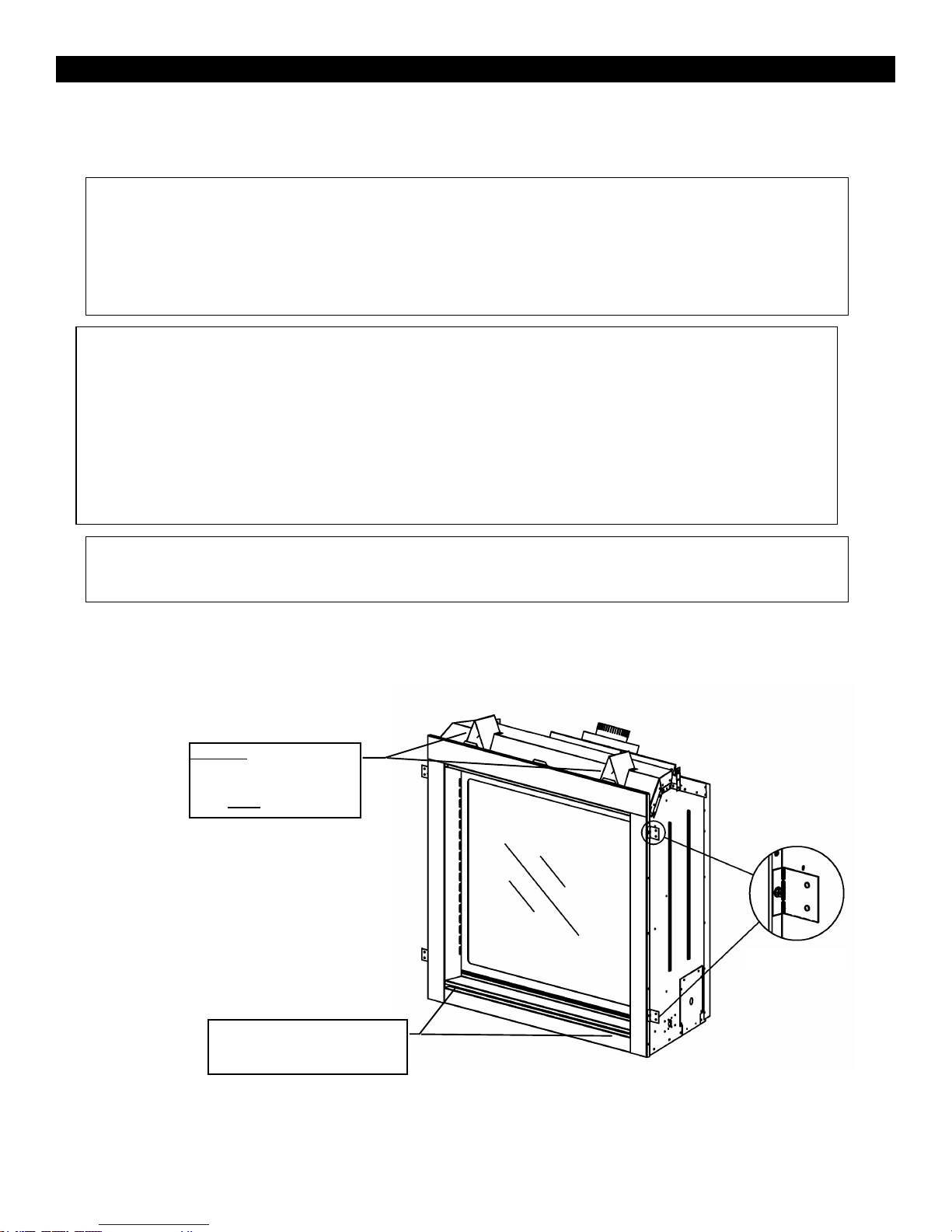
Nailing Tabs
Caution: Standoffs on top
of the unit must be folded
into position & screwed
down Prior to installation.
Holes are provided in bottom of
unit to secure appliance to floor
after installation.
11
located on the unit. This will streamline the construction process. Furthermore, familiarize yourself with the venting and
clearance requirements (see Venting section) for this appliance. Failure to comply with those requirements can seriously
compromise the safety and operation of the fireplace.
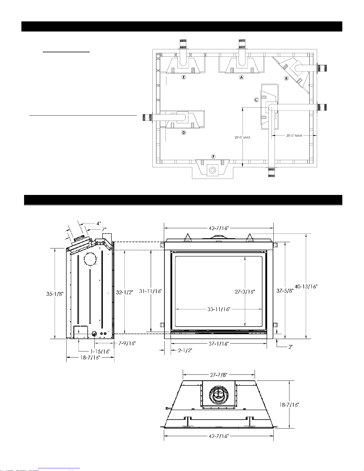
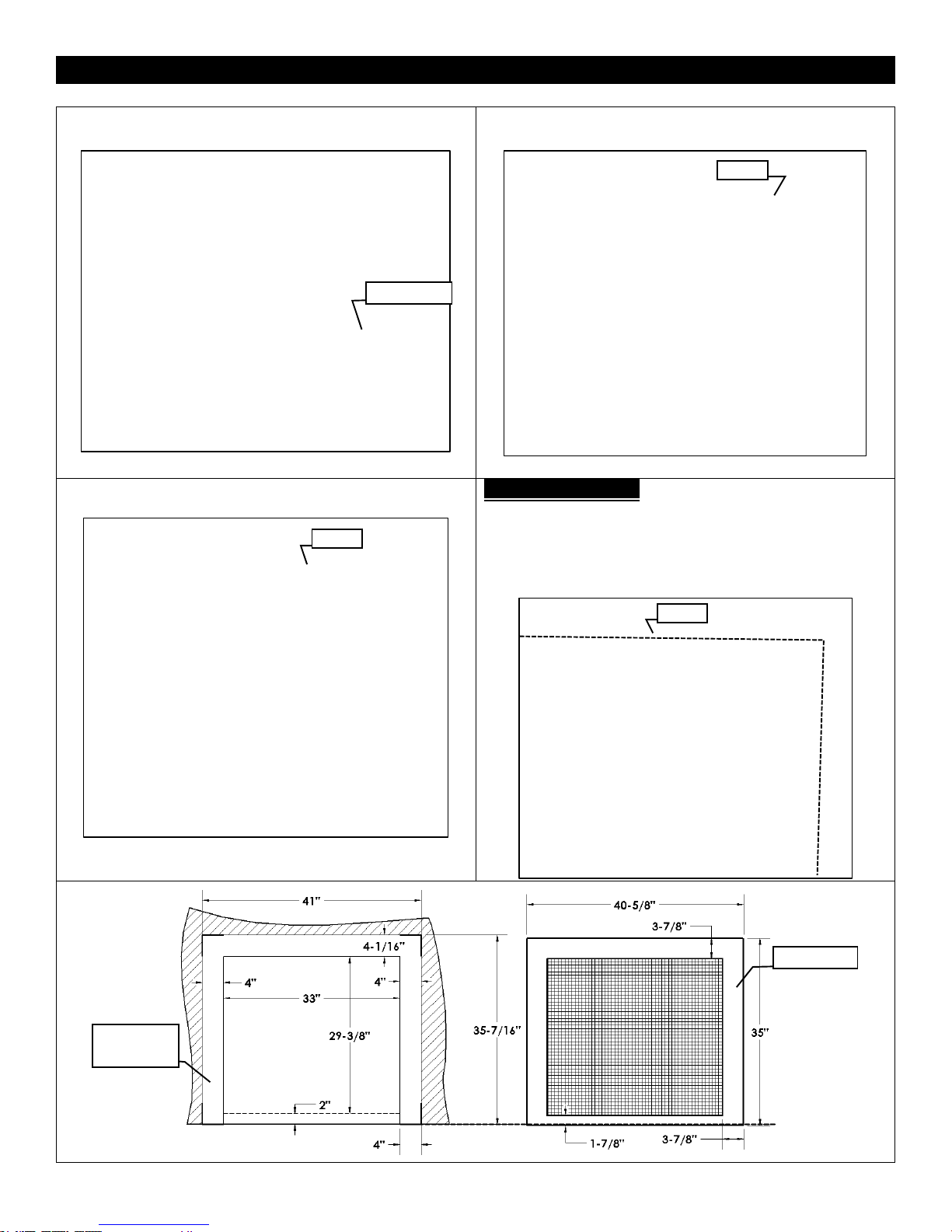
ZCV39 Locating Your Appliance
ZCV39 Fireplace Dimensions
LEFT SIDE
FRONT
TOP
12
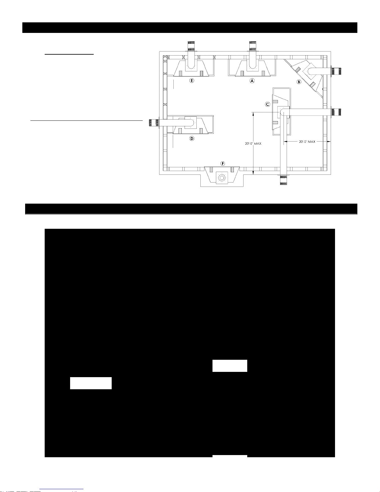
LOCATION KEY:
A. Flat on Wall
B. Across the Corner
C. As an Island
D. As a Room Divider
E. Flat on Wall Corner
F. Exterior Wall
See Mantel Leg Clearances Instruction for
the proper placement of fireplace.
Island installation with a top vent is
possible as long as the horizontal portion
of the vent system does not exceed 20
feet (6.1 m).
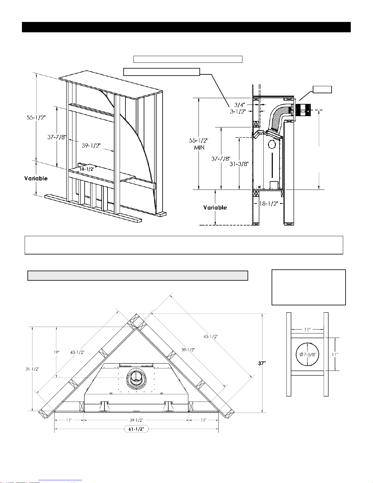
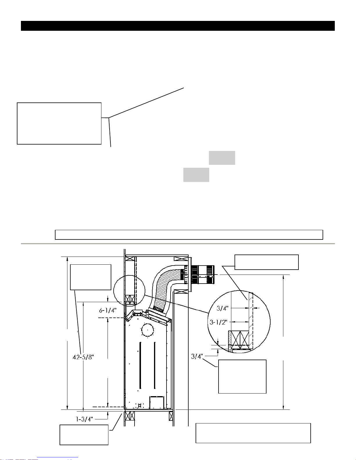
ZCV39 Framing Dimensions
Determine whether face of fireplace will be:
48” MIN for NG
60” MIN for LP
Plus Rise of 1/4”
Per Foot*
Fig.1
Framing for Horizontal Vent
Termination
(See Installation of Side
Wall Venting Section)
Vertical Venting MUST maintain 1” clearance to combustibles.
These structures are not load bearing.
Fig. 1
Recessed Combustible Wall
RIGHT SIDE
*For Propane Horizontal installations the venting must be an additional one foot above
the minimum vertical rise off the flue before going horizontal.
13
Flush with finished wall (e.g., for surround, cultured stone or other non combustible covering).
Flush with framing (to be covered with concrete board for a Flat Wall appearance).
Refer to Nailing Tab Guide section also.
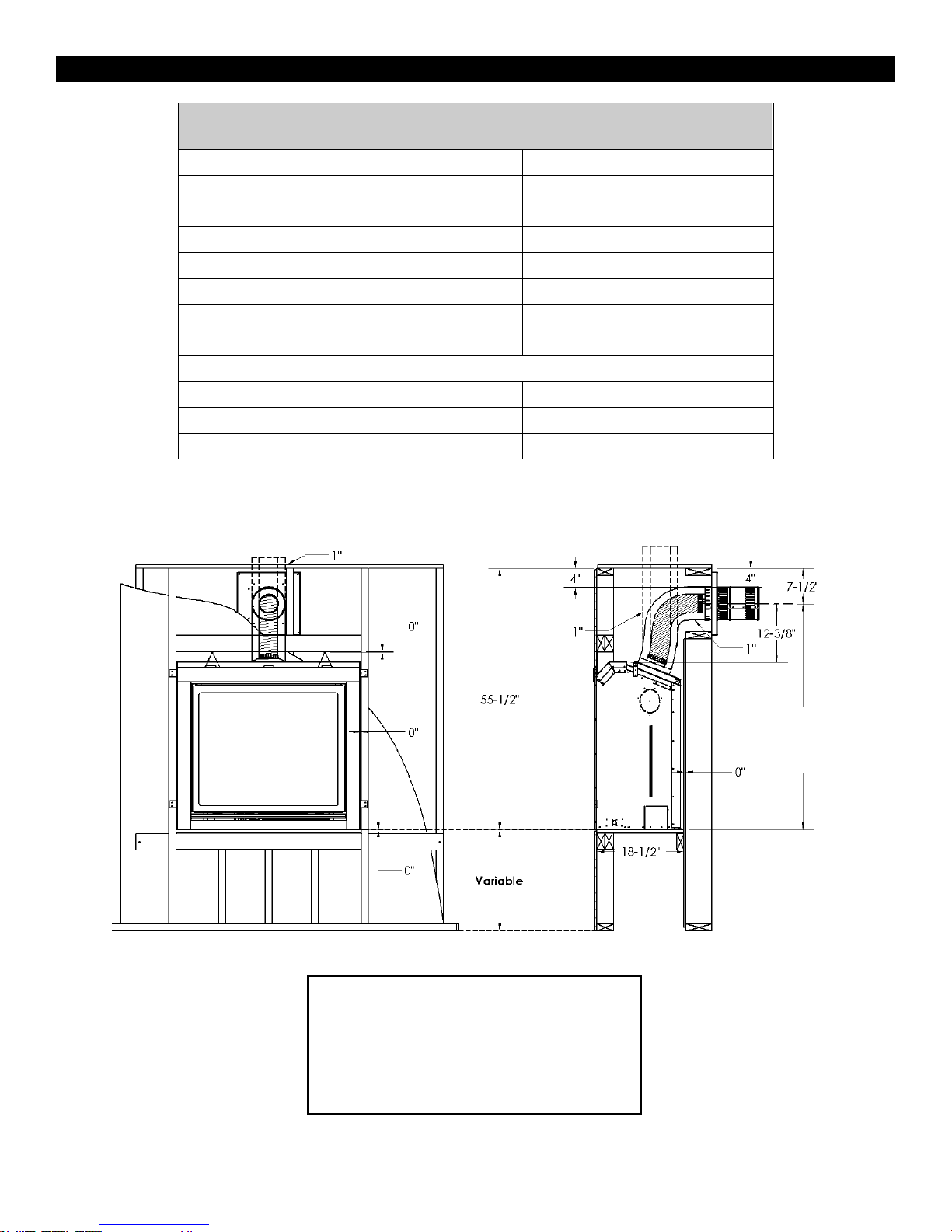
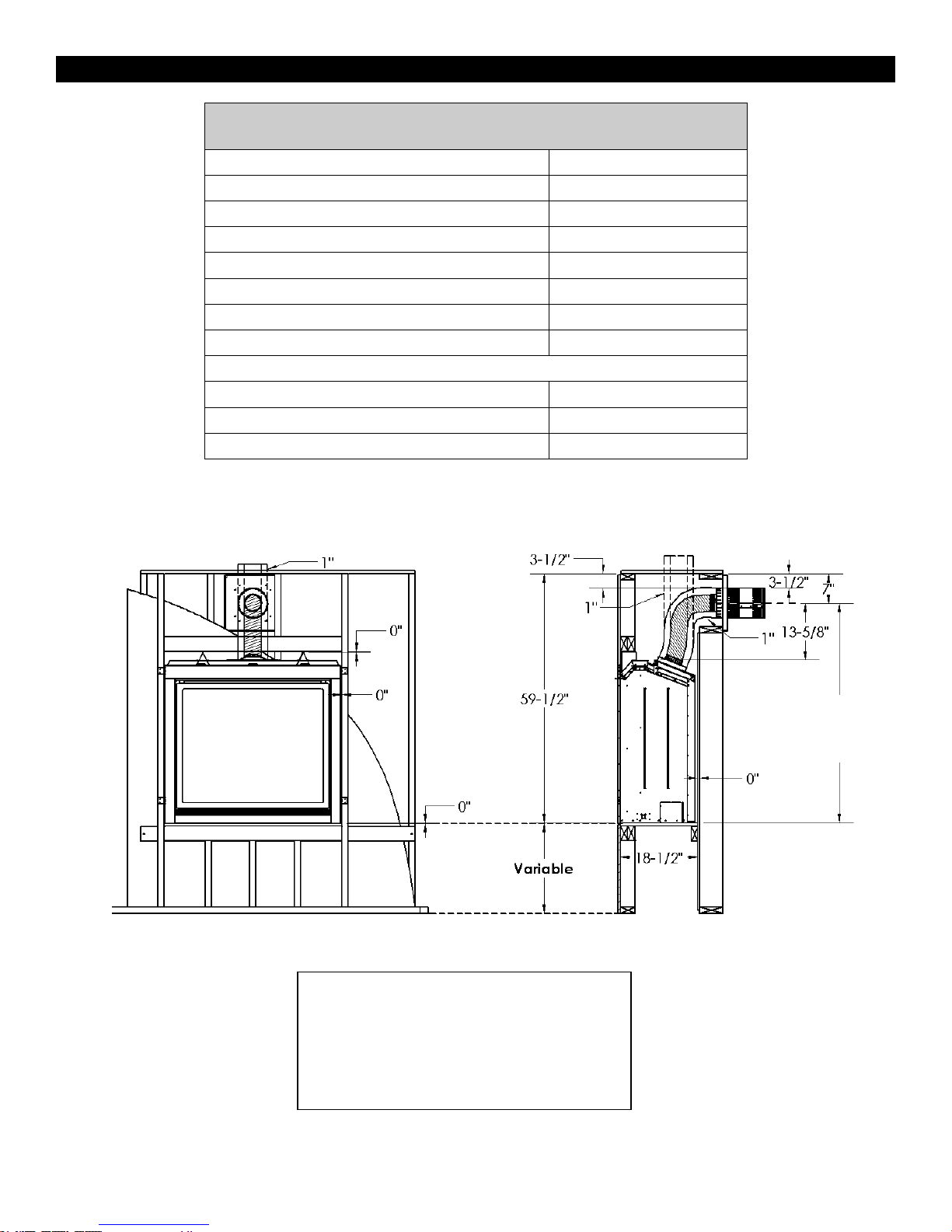
ZCV39 Clearance to Combustibles
Clearance to Combustibles ZCV39
Front
36” [92cm]
Back (from Stand-offs)
0” [0cm]
Side (from Stand-offs)
0” [0cm]
Floor*
0” [0cm]
Minimum Ceiling Height (from bottom of fireplace)
55-1/2” [141cm]
Top (from Stand-offs)
0” [0cm]
Top of 90° Bend in minimum Enclosure of 55-1/2”
4” [10.2cm]
Top of 90° Bend in Enclosure over 55-1/2”
4” [10.2cm]
VENTING SYSTEMS
Top of Horizontal Pipe
1/1/2” [3.8cm]
Side & Bottom of Horizontal Pipe
1” [2.5cm] All Vent Systems
Vertical Vent Pipe
1” [2.5cm] All Vent Systems
*Note: If appliance is installed directly on
carpeting or other combustible material
other than wood flooring, a metal or wood
panel extending the full width and depth of
the appliance must be used. Carpet may
extend 1 inch above the floor of the
appliance.
48” MIN for NG
60” MIN for LP
Plus Rise of 1/4”
Per Foot*
14
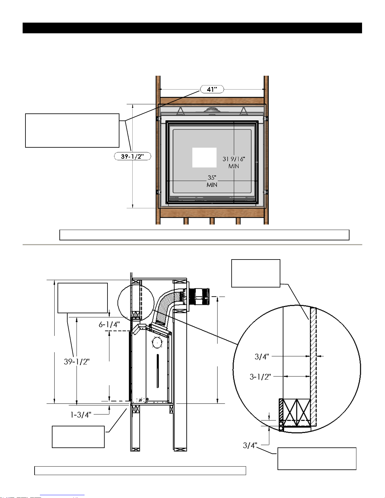
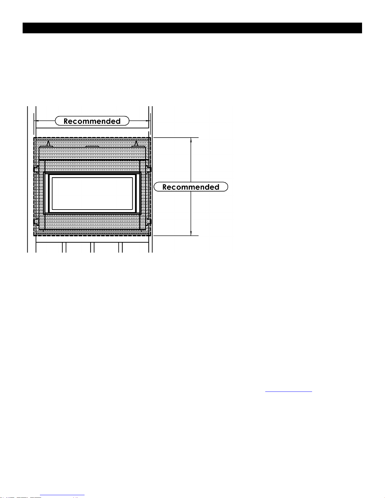
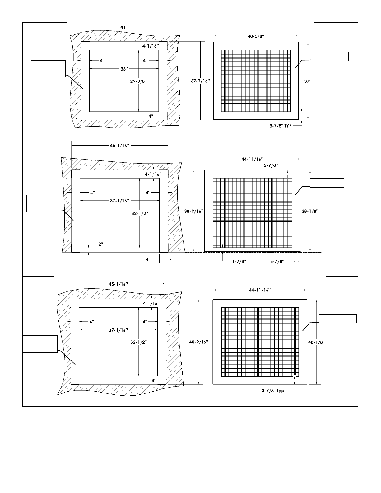
ZCV39 Facing Requirements Required Non-Combustible Areas
NOTE: ANY MATERIALS COVERING THE FACE OF THE FIREPLACE MUST BE NON-COMBUSTIBLE (i.e. brick,
This area can have
a combustible
surface (i.e. hearth)
Note: Do not drive excessively long screws into the face of the unit as internal parts may be damaged.
Recommended
(Not Necessary)
Non-Combustible 39-1/2” x 41”
This is to allow concrete board to be
screwed to framing if used.
Recommended Non-
Combustible (i.e. Concrete
Board) Screwed to Framing
Recessed
Combustible Wall
for TV, etc.
(Optional)
Refer to BASIC FINISHING Sections 1-6 for important finishing details.
Recommended Non-
Combustible (i.e.
Concrete Board) 39-
1/2” x 41”Screwed to
Framing
31-9/16”
Fireplace
Opening
48” MIN for NG
60” MIN for LP
Plus Rise of
1/4” Per Foot*
ZCV39
Fireplace
Opening
55-1/2”
MIN
15
stone, tile, concrete board).
FIREPLACE WITH SCREEN ONLY (AS SHIPPED) SHOWN HERE.
Refer to BASIC FINISHING Sections 1-6 for important finishing details.
ZCV42 Locating Your Appliance
ZCV42 Fireplace Dimensions
LEFT SIDE
FRONT
TOP
16
LOCATION KEY:
A. Flat on Wall
B. Across the Corner
C. As an Island
D. As a Room Divider
E. Flat on Wall Corner
F. Exterior Wall
See Mantel Leg Clearances Instruction for
the proper placement of fireplace.
Island installation with a top vent is
possible as long as the horizontal portion
of the vent system does not exceed 20
feet (6.1 m).
ZCV42 Framing Dimensions
Determine whether face of fireplace will be:
52-1/2” MIN for NG
64-1/2” MIN for LP
Plus Rise of 1/4” Per
Foot*
Fig.1
Framing for Horizontal Vent
Termination
(See Installation of Side
Wall Venting Section)
Vertical Venting MUST maintain 1” clearance to combustibles.
These structures are not load bearing.
Fig. 1
Recessed Combustible Wall
RIGHT SIDE
*For Propane Horizontal installations the venting must be an additional one foot above
the minimum vertical rise off the flue before going horizontal.
17
Flush with finished wall (e.g., for surround, cultured stone or other non combustible covering).
Flush with framing (to be covered with concrete board for a Flat Wall appearance).
Refer to Nailing Tab Guide section also.
ZCV42 Clearance to Combustibles
Clearance to Combustibles ZCV42
Front
36” [92cm]
Back (from Stand-offs)
0” [0cm]
Side (from Stand-offs)
0” [0cm]
Floor*
0” [0cm]
Minimum Ceiling Height (from bottom of fireplace)
59.5” [151cm]
Top (from Stand-offs)
0” [0cm]
Top of 90° Bend in minimum Enclosure of 59.5”
3-1/2” [8.9]
Top of 90° Bend in Enclosure over 59.5”
3-1/2” [8.9]
VENTING SYSTEMS
Top of Horizontal Pipe
1/1/2” [3.8cm]
Side & Bottom of Horizontal Pipe
1” [2.5cm] All Vent Systems
Vertical Vent Pipe
1” [2.5cm] All Vent Systems
*Note: If appliance is installed directly on
carpeting or other combustible material
other than wood flooring, a metal or wood
panel extending the full width and depth of
the appliance must be used. Carpet may
extend 1 inch above the floor of the
appliance.
52-1/2” MIN for NG
64-1/2” MIN for LP
Plus Rise of 1/4”
Per Foot*
18
ZCV42 Facing Requirements Required Non-Combustible Areas
NOTE: ANY MATERIALS COVERING THE FACE OF THE FIREPLACE MUST BE NON-COMBUSTIBLE (i.e. brick,
Note: Do not drive excessively long screws into the face of the unit as internal parts may be damaged.
Recommended:
(Not Necessary)
Non-Combustible 42-5/8” x 44”
This is to allow concrete board
to be screwed to framing if
used.
Recommended
Non-Combustible
(i.e. Concrete
Board) Screwed to
Framing
Recessed Combustible
Wall for TV, etc. (Optional)
Recommended Non-
Combustible (i.e.
Concrete Board) 42-
5/8” x 44”Screwed to
Framing
34-11/16”
MIN
34-11/16”
Fireplace
Opening
ZCV42
Fireplace
Opening
52-1/2” MIN for NG
64-1/2” MIN for LP
Plus Rise of 1/4”
Per Foot*
39-1/8”
MIN
59-1/2”
MIN
This area can have
a combustible
surface (i.e. hearth)
Refer to BASIC FINISHING Sections 1-6
for important finishing details.
19
stone, tile, concrete board).
FIREPLACE WITH SCREEN ONLY (AS SHIPPED) SHOWN HERE.
Refer to BASIC FINISHING Sections 1-6 for important finishing details.
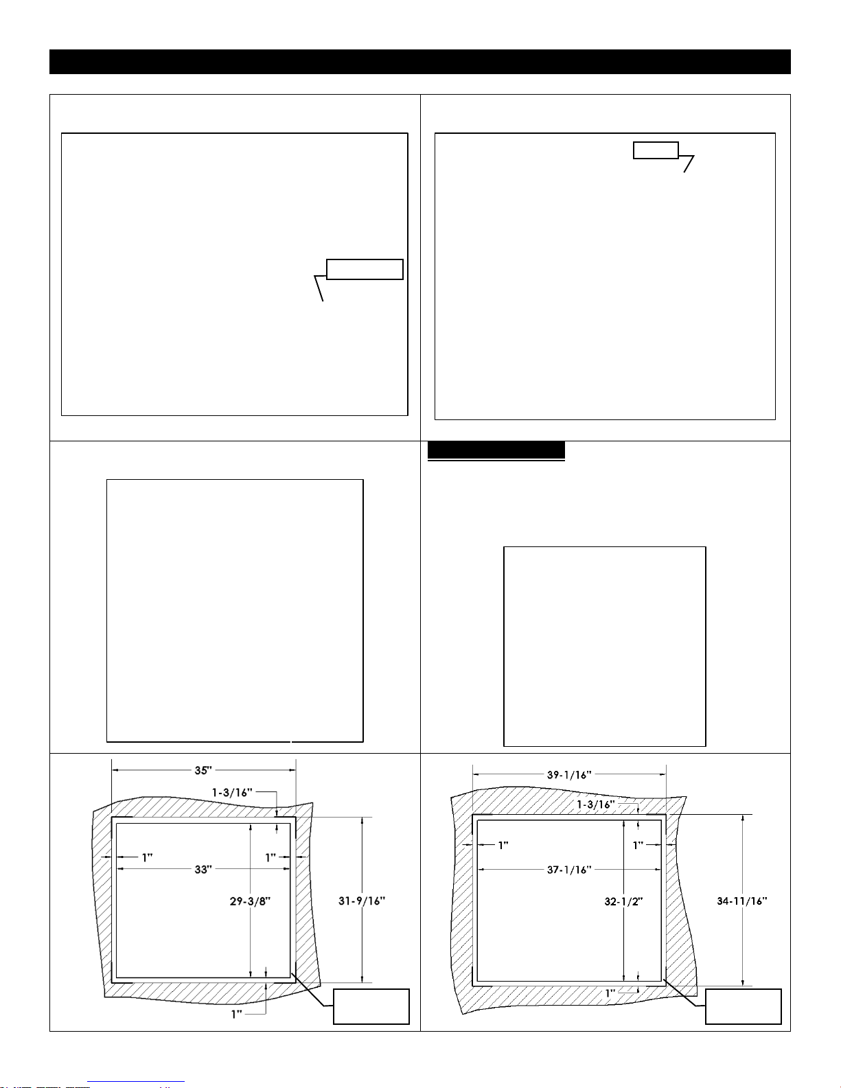
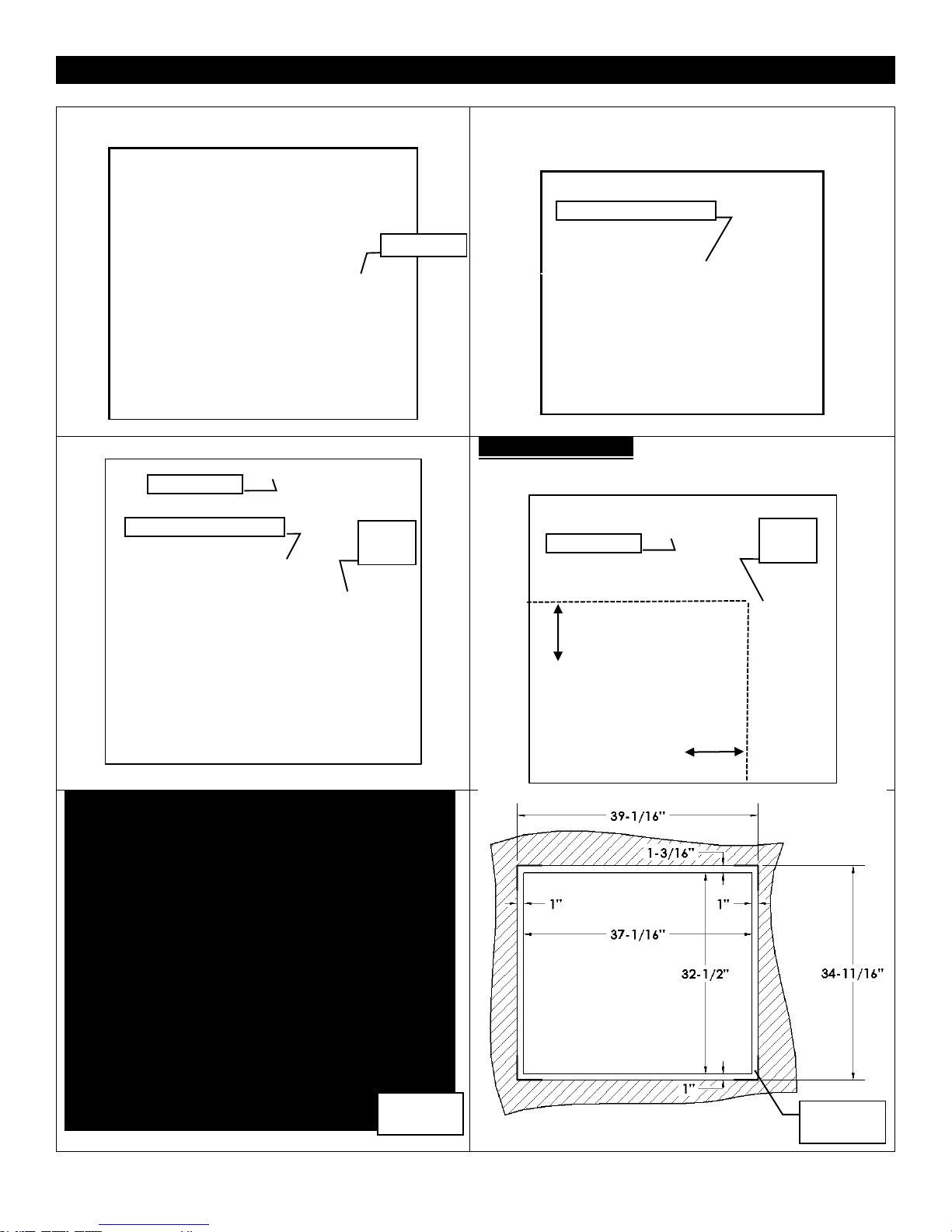
ZCV39 / ZCV42 Basic Finishing 1: With Screen Only
Step One: Frame Fireplace with nailing tabs oriented as
shown.
Step Two: Use Drywall to finish face of wall.
NOTE: Drywall will be flush with fireplace face.
Step 3: A brick, tile, or other non-combustible border may
be applied over fireplace face to conceal border.
IMPORTANT NOTE!: If installing tile, brick, or other non-
combustible material around the perimeter of the screen: you
MUST Leave 1” of the face exposed around the fireplace
opening on the Bottom and Sides, and 1-3/16” exposed on the
top. This is to install and remove the safety screen. See
drawings below. A Tile Lip Kit is Available. Part No. ZCV-TLK
Nailing Tab
1-3/16” MIN
Drywall
1” MIN
Fireplace Frame
ZCV42
Fireplace
Opening
ZCV39
Fireplace
Opening
Required
Clearance
Required
Clearance
20
ZCV39 / ZCV42 Basic Finishing 2: With S1 or S1PF Surround
Step One: Frame Fireplace with nailing tabs oriented as
shown.
Step Two: Use Drywall to finish face of wall.
NOTE: Drywall will be flush with fireplace face.
Step 3: Once wall is completely finished, Screen with Surround
may be installed. Surround will conceal edges of fireplace.
IMPORTANT NOTE!: If installing tile, brick, or other non-
combustible material around the perimeter of the surround:
you MUST Leave 4” of the face exposed around the fireplace
opening on the Bottom and Sides, and 4-1/16” exposed on the
top. This is to install and remove the surround. See drawings
below. A Tile Lip Kit is Available. Part No. ZCV-TLK
Nailing Tab
4-1/16” MIN
ZCV39
Fireplace
Opening
Drywall
4” MIN
Fireplace Frame
Required
Clearance
S1 Surround
Drywall
S1 or S1PF Surround
Drywall
(Continued on Next Page)
21
S1PF Surround
Required
Clearance
ZCV39
Fireplace
Opening
S1 Surround
S1PF Surround
ZCV42
Fireplace
Opening
ZCV42
Fireplace
Opening
Required
Clearance
Required
Clearance
22
ZCV39 / ZCV42 Basic Finishing 3: Concrete Board Behind S2PF Surround (3/4” Maximum Total Thickness)
Step One: Frame Fireplace with nailing tabs oriented as
shown (flush with face of fireplace).
Step Two: Use Concrete Board to cover fireplace face.
NOTE: Optional ZCV-TLK Tile Kit is available. Maintain
clearances shown. See bottom drawings also.
Step 3: Concrete Board with optional Tile Lip shown below.
IMPORTANT NOTE!: If installing tile, brick, or other non-
combustible material around the perimeter of the S2PF2 Surround,
Maintain clearances shown below. Also See Basic Finishing 4.
Nailing Tab
Optional ZCV-TLK Tile Kit
1-3/16” MIN
1” MIN
Concrete
Board
Concrete Board
S2PF Surround
1” MIN
1-3/16” MIN
Optional ZCV-TLK Tile Kit
Concrete
Board
Concrete Board
1-3/4” MIN
1-15/16” MIN
ZCV39
Fireplace
Opening
Required
Clearance
ZCV42
Fireplace
Opening
Required
Clearance
23
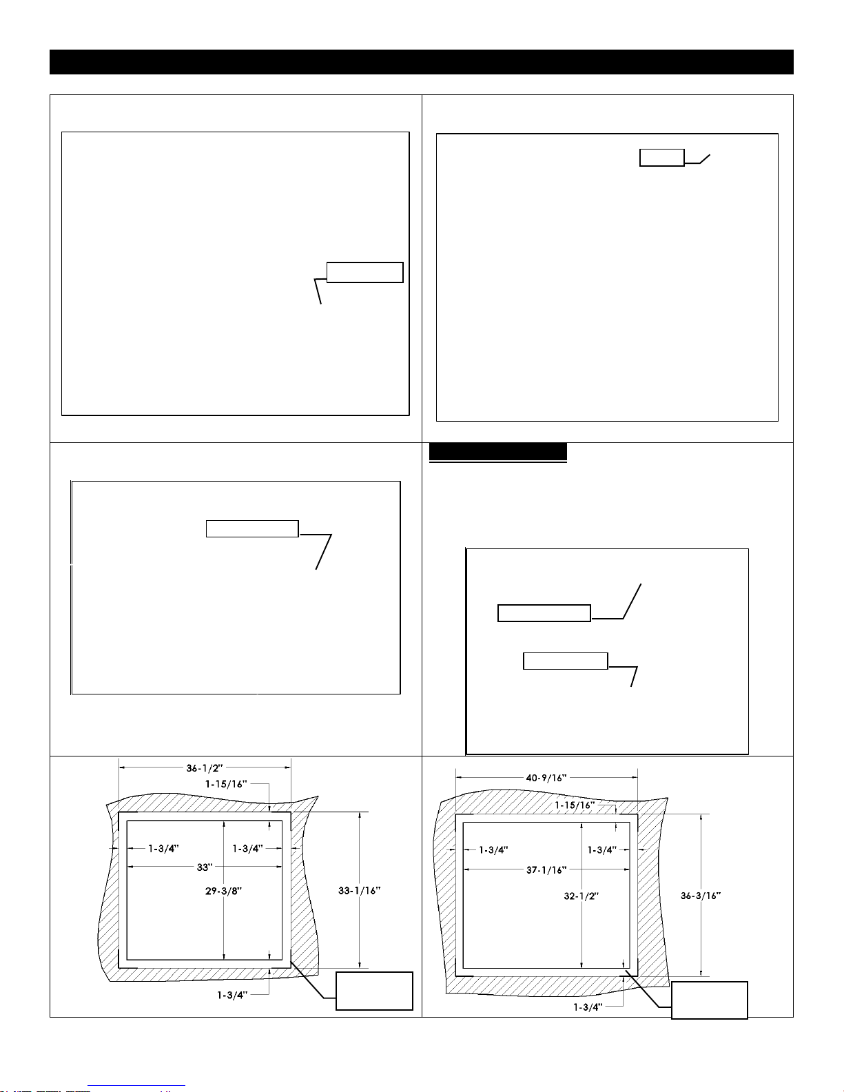
ZCV39 / ZCV42 Basic Finishing 4: Stone or Brick Around S2PF Surround
Step One: Frame Fireplace with nailing tabs oriented as
shown.
Step Two: Use Drywall to finish face of wall.
NOTE: Drywall will be flush with fireplace face.
Step 3: A stone, brick, or other non-combustible border
may be applied over fireplace face to conceal border.
IMPORTANT NOTE!: If installing stone, brick, or other non-
combustible material around the perimeter of the surround:
you MUST Leave 1-3/4” of the face exposed around the
fireplace opening on the Bottom and Sides, and 1-15/16”
exposed on the top. This is to install and remove the surround.
See drawings below. A Tile Lip Kit (ZCV-TLK) is available.
Nailing Tab
1-15/16” MIN
Drywall
1-3/4” MIN
Fireplace Frame
Stone, Brick, etc.
S2PF Surround
Stone, Brick, etc.
ZCV39
Fireplace
Opening
Required
Clearance
ZCV42
Fireplace
Opening
Required
Clearance
24
 Loading...