

Page 1
Installation Instructions
Model Number VFI30 Gas Fired Direct Vent Room
Heater Inserts
Model VFI30 Listed Certified for USA, and Canada
Minimum Fireplace Opening Required: 29”W x 20 3/4”H x 16 1/2”D
Certified to: ANZI Z21.88-2009, CSA2.33-2009
Read this complete manual before beginning installation.
These instructions must be kept with the unit for future reference.
FOR YOUR SAFETY
WARNING: If the information in these instructions is not
followed exactly, a fire or explosion may result causing property
damage, personal injury or loss of life.
WARNING: The VFI30
Fireplace Insert was designed for
installation in a solid fuel fireplace
that has been installed in
accordance with national,
provincial/state and local building
codes and is constructed of
noncombustible materials. Do not
remove any refractory materials
from any masonry solid fuel
fireplace.
The VFI30 Fireplace Insert was
designed for installation in a zero
clearance type listed solid fuel
burning factory built fireplace. It may
be necessary to remove the damper
plate, refractory liners, log grates,
glass door, and screen rails/mesh.
Removal of the smoke baffle is
necessary in most cases.
WARNING: Improper installation, adjustment, alteration,
service or maintenance can cause property damage, personal
injury or loss of life. Refer to this manual. Installation and service
must be performed by a qualified installer, service agency or the
gas supplier.
Do not store or use gasoline or other flammable vapors and liquids
in the vicinity of this or any other appliance.
What to Do If You Smell Gas
Do not try to light any appliance.
Extinguish any open flame.
Do not touch any electrical switch.
Do not use any phone in your building.
Immediately call your gas supplier from a neighbour’s phone.
If you can not reach your gas supplier, call the fire department.
A Division of R-Co. Inc.
2340 Logan Avenue
Winnipeg, Manitoba, Canada R2R 2V3
Ph: (204) 632-1962
Printed in Canada October 19, 2009 30 VFI-MAN
INSTALLER: Leave this manual with the appliance.
CONSUMER: Retain this manual for future reference.
This appliance may be installed in an aftermarket permanently located, manufactured home (USA only) or mobile
home, where not prohibited by local codes.
This appliance is only for use with the type of gas indicated on the rating plate. This appliance is not convertible
for use with other gases, unless a certified kit is used.
Page 2

2
Why does my fireplace or stove give off odour?
It is normal for your fireplace to give off some odour. This is due to the curing of the paint, adhesives, silicones
and any undetected oil from the manufacturing process as well as the finishing materials used with the installations (e.g. marble, tile and the adhesives used to adhere this product to the walls can react with heat and cause
odours).
It is recommended that you burn your gas fireplace or stove for a minimum of four hours at a time with the fan off
after the curing of the paint has been completed. These odours can last upward to 40 hours of burn time, keep
burning at a minimum of four hours per use until odours dissipate.
About curing of the paint
Your stove or fireplace has been painted with the highest quality silicone stove paint. This paint dries quickly in
15-20 minutes when first applied at the factory. However, due to the high temperature silicone components, the
paint will cure when heat is applied to the appliance as it is first used.
The following information applies to the curing process to get the paint fully hard and durable.
Fire the appliance four successive times for 10 minutes each firing and a 5 minute cool down between each. Be
aware during log and firebox paint curing that a white deposit may be developing on the inside of the glass
doors. It is important to remove this white deposit from the glass doors with an appropriate cleaner to prevent
build-up (such as Windex or a commercial fireplace glass cleaner).
• Babies, small children, pregnant women and pets should leave the area during the cure phase.
• Ventilate well, open doors and windows.
• Do not touch during curing.
Noise coming from the fireplace?
• Noise caused by metal expanding and contracting as it heats up and cools down, similar to the sound pro-
duced by a furnace or heating duct. This noise does not affect the operation or longevity of your fireplace.
• Different types and thicknesses of steel will expand and contract at different rates resulting in “cracking”
and “ticking” sounds throughout the heating and cooling periods.
• You should also be aware that as temperatures change within the unit these sounds will likely re-occur.
Again this is normal for steel fireboxes, and is not a defect.
Cleaning the Glass
During the first few fires, a white film may develop on the glass front, as part of the curing process. The glass
should be cleaned after the unit has cooled down or the film can bake on and become very difficult to remove.
Use a non-abrasive cleaner and do not attempt to clean the glass while it is hot.
PRE-INSTALLATION QUESTIONS and ANSWERS
Page 3

3
1. Pre-Installation Questions and Answers . . . . . . . . . . . . . . . .2
2. Table of Contents . . . . . . . . . . . . . . . . . . . . . . . . . . . . . . . . . .3
3. Mobile Home /Manufactured Housing Installations . . . . . . . .4
4. Warnings, Installations and Operations . . . . . . . . . . . . . . . . .5
5. Operations and Maintenance Instructions . . . . . . . . . . . . . . .6
6. Installation Requirements for the
Commonwealth of Massachusetts . . . . . . . . . . . . . . . . . . . . .6
7. Unit Identification . . . . . . . . . . . . . . . . . . . . . . . . . . . . . . . . . .7
8. Heat Output . . . . . . . . . . . . . . . . . . . . . . . . . . . . . . . . . . . . . .7
9. Unpacking the Insert . . . . . . . . . . . . . . . . . . . . . . . . . . . . . . .7
10. Clearances . . . . . . . . . . . . . . . . . . . . . . . . . . . . . . . . . . . . . . .7
11. Electrical Connections . . . . . . . . . . . . . . . . . . . . . . . . . . . . . .7
12. Gas Piping . . . . . . . . . . . . . . . . . . . . . . . . . . . . . . . . . . . . . . .8
13. Venting . . . . . . . . . . . . . . . . . . . . . . . . . . . . . . . . . . . . . . . . . .8
14. Installation . . . . . . . . . . . . . . . . . . . . . . . . . . . . . . . . . . . . . .10
Log Placement C5 or F5 . . . . . . . . . . . . . . . . . . . . . . . . . . .11
Log Placement C6 . . . . . . . . . . . . . . . . . . . . . . . . . . . . . . . .12
15. Field Conversion for ZDV6000-VFI25-VFI30 . . . . . . . . . . . .13
16. Combustion Air . . . . . . . . . . . . . . . . . . . . . . . . . . . . . . . . . . .14
17. Unit Operation & Checkout . . . . . . . . . . . . . . . . . . . . . . . . . .14
18. Check-out . . . . . . . . . . . . . . . . . . . . . . . . . . . . . . . . . . . . . . .15
19. Unit Adjustment . . . . . . . . . . . . . . . . . . . . . . . . . . . . . . . . . .15
20. Maintenance . . . . . . . . . . . . . . . . . . . . . . . . . . . . . . . . . . . . .16
21. Bay Window Installation . . . . . . . . . . . . . . . . . . . . . . . . . . . .17
22. Surround and Brass Trim Assembly Instructions . . . . . . . . .19
and Parts List . . . . . . . . . . . . . . . . . . . . . . . . . . . . . . . . . . . .20
23. Wiring Diagram - SIT Valve System . . . . . . . . . . . . . . . . . . .21
24. Wiring Diagram - Robertshaw Valve System . . . . . . . . . . . .22
25. Accessory List . . . . . . . . . . . . . . . . . . . . . . . . . . . . . . . . .23-24
26. Replacement Parts . . . . . . . . . . . . . . . . . . . . . . . . . . . . .25-26
27. Lighting Instructions . . . . . . . . . . . . . . . . . . . . . . . . . . . . . . .27
Kingsman Industries Warranty . . . . . . . . . . . . . . . . . . . . . . .28
Table of Contents
Page 4
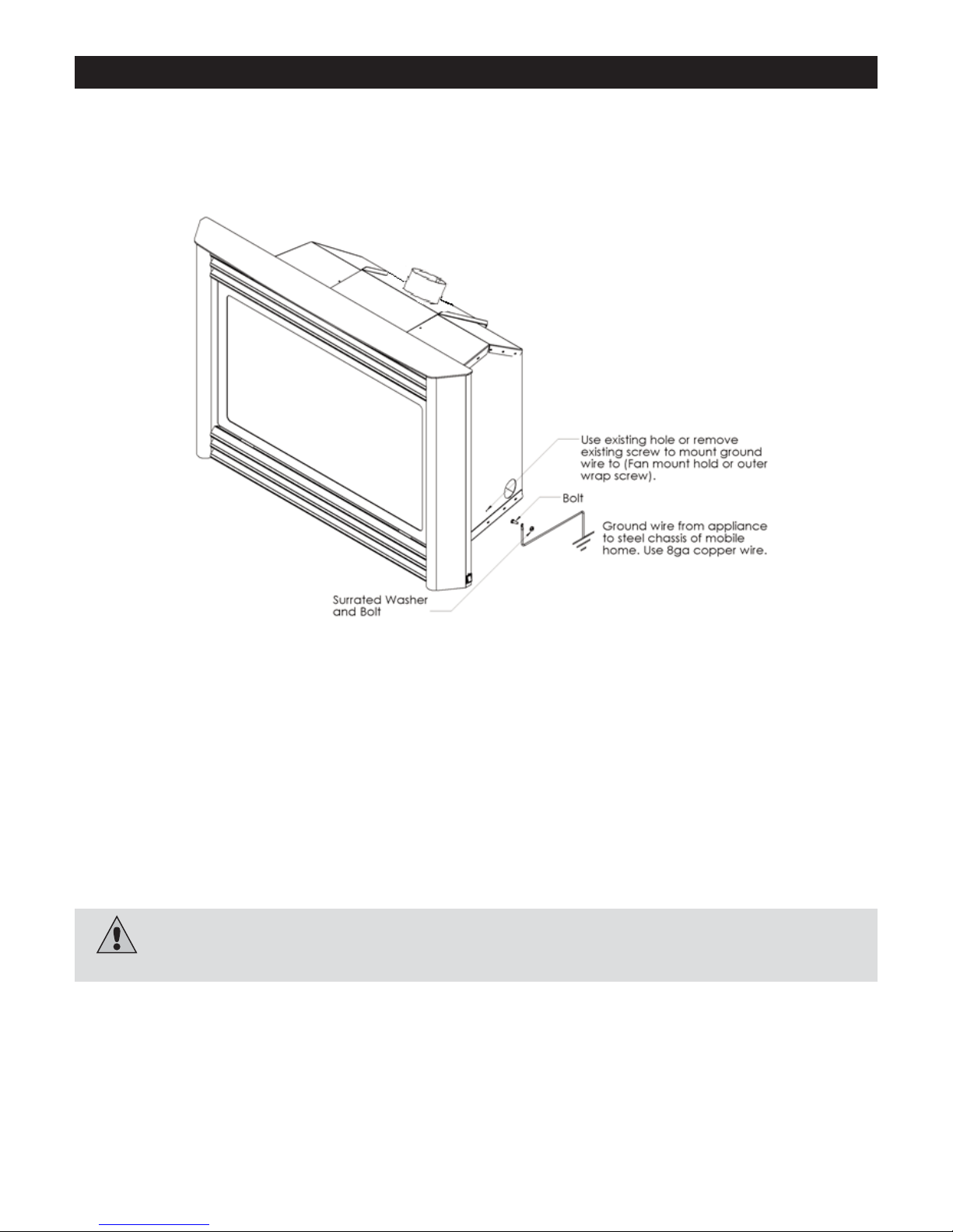
Mobile Home/Manufactured Housing Installation
THIS APPLIANCE MAY BE INSTALLED IN MANUFACTURED (MOBILE) HOMES AFTER FIRST SALE.
Please follow the current ANSI/NFPA 70 National Electrical Code in the USA and CAN/CSA C22.1 Canadian
National Electrical Code in Canada.
An appliance must be grounded to the steel chassis of the home with 8ga. copper wire using a serrated or star washer to penetrate paint or protective coating to insure grounding.
Use carriage bolt at the attachment point (see diagram above) to secure the appliance to the floor.
Bedroom approved.
Warning: Do not compromise the structural integrity of the manufactured home wall, floor or ceiling,
during installation of appliance or venting.
For required venting components see venting installation in appropriate section of this manual.
This Vent System Appliance must be installed in accordance with the manufacturer’s installation instructions and the
Manufactured Home Construction and Safety Standard Title 24 CFR, Part 3280, or the current Standard for Fire
Safety Criteria for Manufactured Home Installation, Sites, and Communities ANSI/NFPA 501A, and with CAN/CSA
Z240 MH Mobile Home Standard in Canada.
4
Page 5
Warnings, Installations, and Operations
Warning
• Gas fired appliances may be used only for supplemental heat and/or decorative purposes and under no circumstances
shall they provide a primary heat source.
FOR SAFE INSTALLATION AND OPERATION OF YOUR GAS FIREPLACE PLEASE NOTE THE FOLLOWING:
1. Do not clean when the glass is hot.
2. Do not use abrasive cleaners.
3. Using a substitute glass will void all product warranties.
4. For safe operation, glass doors must be closed.
5. When purging the gas line, the glass front must be
removed.
6. Do not strike or abuse glass. Take care to avoid breakage.
7. Do not alter gas orifice.
8. No substitute materials may be used other than factory
supplied components.
9. This appliance gives off high temperatures and should be located out of heavy traffic areas and away from furniture and
draperies.
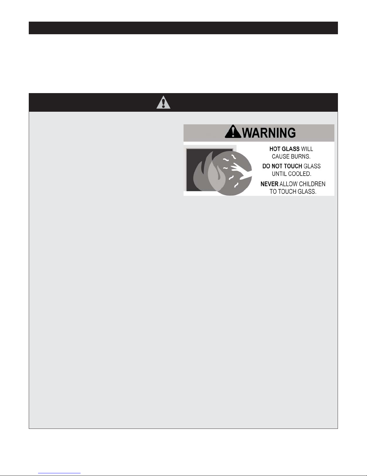
10. Children and adults should be alerted to the hazards of the high surface temperatures of this appliance and should stay
away to avoid burns or ignition of clothing.
11. Young children should be carefully supervised when they are in the same room as the appliance. Toddlers, young children
and others may be susceptible to accidental contact burns. A physical barrier is recommended if there are at risk individuals in the house. To restrict access to a fireplace or stove, install an adjustable safety gate to keep toddlers, young children
and other at risk individuals out of the room and away from hot surfaces.
12. Under no circumstances should any solid fuels (wood, paper) be used in this appliance.
13. Under no circumstances should this appliance be modified. Any parts that have to be removed for servicing should be
replaced prior to operating this appliance.
14. Installation and repair should be done by a qualified service person. The appliance should be inspected before use and at
least annually by a professional service person. More frequent cleaning may be required due to excessive lint from carpeting, bedding material, et cetera. It is imperative that control compartments, burners and circulating air passageways of the
appliance be kept clean. Make sure that the gas valve and pilot light are turned off before you attempt to clean this unit.
15. Clothing or other flammable material should not be placed on or near the appliance. This appliance should not be used as
a drying rack for clothing nor should Christmas stockings or decorations be hung from it.
16. Do not use this heater if any part has been under water. Immediately call a qualified service technician to inspect the
heater and to replace any part of the control system and any gas control which has been under water.
17. Do not operate appliance unless completely installed as per installation instructions.
18. Failure to position the parts in accordance with these diagrams or failure to use only parts specifically approved with this
appliance may result in property damage or personal injury.
19. Do not operate appliance with the glass front removed, cracked or broken. Replacement of the glass should be done by a
licensed or qualified service person.
20. The front of the fireplace gives off high temperatures that could ignite combustible material which is kept close to the front
of the unit.
21. Ensure that power to the Fireplace is turned off before servicing.
22. Do not operate this Fireplace without the glass front or with a broken glass.
23. Improper installation, adjustment, alteration, service or maintenance can cause injury or property damage. Refer to the
owner’s information manual provided with this appliance. For assistance or additional information consult a qualified
installer, service agency, or the gas supplier.
24. Operation of this appliance when not connected to a properly installed and maintained venting system or tampering with
the blocked vent shutoff system can result in carbon monoxide (CO) poisoning and possible death.
Installation Regulations
This gas appliance must be installed by a qualified installer in accordance with local building codes, or in the absence of local
codes, with the current CAN/CGA-B149.1 Installation Code (in Canada) or the current National Fuel Gas Code Z223.1 when
installed in the United States.
This appliance, when installed, must be electrically connected and grounded in accordance with local codes, or in the absence of
local codes, with the current CSA C22.1 Canadian Electrical Code or with the national Electrical Code; ANSI/NFPA 70-1987 when
installed in the United States.
5
Page 6
6
• If the factory-built fireplace has no gas access hole(s) provided, an access hole of 1.5in [37.5mm] or less may be drilled
through the lower sides or bottom of the firebox in a proper workmanship like manner. This access hole must be plugged with
non-combustible insulation after the gas supply line has been installed.
• Cutting any sheet-metal parts of the fireplace, in which the gas fireplace insert is to be installed, is prohibited.
• This appliance must not be connected to a chimney flue serving a separate solid-fuel burning appliance.
• Installer must mechanically attach the supplied label to the inside of the fireplace into which the gas fireplace insert is installed.
NOTE: It is recommended that a Carbon Monoxide (CO) Detector be installed in or near bedrooms and on all levels of your
home. Place a detector about 15ft [4.5m] outside the room that houses your gas appliance.
Certified for installation in a bedroom or bed/sitting room. In Canada must be installed with listed millivolt thermostat. In USA see local codes.
For safe installation and operation note the following:
• The Burner/Log Assembly has been engineered and permanently adjusted for proper flame control.
• Periodically remove the logs from the grate assembly and vacuum any loose particles from the grate and burner areas. See
Log Placement page to remove logs. Vacuum burner parts and replace logs.
• Label all wires prior to disconnection when servicing controls. Wiring errors can cause improper and dangerous operation.
Verify proper operation after servicing.
In the Commonwealth of Massachusetts, the installer or service agent shall be a plumber or gas fitter licensed by the
Commonwealth.
When installed in the Commonwealth of Massachusetts or where applicable codes; the unit shall be installed with a CO
detector per the requirements listed below.
1. For direct-vent appliances, mechanical-vent heating appliances or domestic hot water equipment, where the bottom of the
vent terminal and the air intake is installed below four feet above grade the following requirements must be satisfied:
A. If there is not one already present, on each floor level where there are bedroom(s), a carbon monoxide detector and
alarm shall be placed in the living area outside the bedroom(s). The carbon monoxide detector shall comply with NFPA
720 (2005 Edition).
B. A carbon monoxide detector shall be located in the room that houses the appliance or equipment and shall:
• Be powered by the same electrical circuit as the appliance or equipment such that only one service switch services
both the appliance and the carbon monoxide detector;
• Have battery back-up power;
• Meet ANSI./UL 2034 Standards and comply with NFPA 720 (2005 Edition); and
• Have been approved and listed by a Nationally Recognized Testing Laboratory as recognized under 527 CMR.
C. A Product-approved vent terminal must be used, and if applicable, a Product-approved air intake must be used.
Installation shall be in strict compliance with the manufacturer’s instructions. A copy of the installation instructions shall
remain with the appliance or equipment at the completion of the installation.
D. A metal or plastic identification plate shall be mounted at the exterior of the building, four feet directly above the loca
tion of vent terminal. The plate shall be of sufficient size to be easily read from a distance of eight feet away, and read
“Gas Vent Directly Below”.
2. For direct-vent appliances, mechanical-vent heating appliances or domestic hot water equipment where the bottom of the
vent terminal and the air intake is installed above four feet above grade the following requirements must be satisfied:
A . If there is not one already present, on each floor level where there are bedroom(s), a carbon monoxide detector and
alarm shall be placed in the living area outside the bedroom(s). The carbon monoxide detector shall comply with NFPA
720 (2005 Edition).
B. A carbon monoxide detector shall:
• Be located in the room that houses the appliance or equipment;
• Be either hard-wired or battery powered or both; and
• Shall comply with NFPA 720 (2005 Edition).
A Product-approved vent terminal must be used, and if applicable, a Product-approved air intake must be used. Installation shall
be in strict compliance with the manufacturer instructions. A copy of the installation instructions shall remain with the appliance or
equipment at the completion of the installation.
For the state of Massachusetts a T-handle gas shut-off valve
must be used on a gas appliance. This T-handle gas shut-off
valve must be listed and approved by the state of Massachusetts. This is in reference to the state of Massachusetts state code
CMR238.
Operations and Maintenance Instructions
Installation Requirements for the Commonwealth of Massachusetts
Warning: This fireplace has been converted for use with a gas fireplace insert only and cannot be used
for burning wood or solid fuels unless all original parts have been replaced, and the fireplace re-approved by
the authority having jurisdiction.
Page 7

With each insert the following must be purchased:
(1) Log Set (4 pce) Cast or Fibre
(1) Standard Surround Kit
(1) Grill Kit
For a list of options please see page 23-24 and contact your local
dealer.
4. CLEARANCES
This fireplace was designed for installation in a solid fuel
fireplace that has been installed in
accordance with National, Provincial/State and Local
building codes and is constructed of non-combustible
materials. DO NOT remove any refractory materials from
any masonry solid fuel fireplace. For installation in zero
clearance type listed solid fuel burning factory built fireplaces, it may be necessary to remove the damper plate
and refractory liners. Removal of the smoke baffle is
necessary in most cases.
Clearance from the front of the unit to a
combustible floor is 0.15 metres( 6 inches).
Clearance from adjacent side wall is 7 inches from
side of unit.
• Minimum clearances from the top of the grill to a mantel and maximum mantel width are:
MANTEL HEIGHT ABOVE
WIDTH GRILL OPENING
A 7”(17.8cm) 13”(33.0cm)
B 6”(15.3cm) 12”(30.5cm)
C 5”( 12.7cm) 11”(27.9cm)
5. ELECTRICAL CONNECTIONS
The blower for the fireplace insert comes
pre-wired from the factory all that is needed is to plug in
to 120 volt supply.
Fan Temperature Sensor
The wiring harness has two wire ends that must be
attached to the Temperature Sensor. The Temperature
Sensor is mounted underneath the burner, attached by
two screws securing the
thermodisc to the bottom of the burner.
(See page 19 for drawing assembly of SIT Wiring
Diagram).
NOTE: MAKE SURE THE WIRE HARNESS IS
ROUTED AGAINST THE SURROUND,
NOT THE SIDE OF THE FIREPLACE.
7
1. UNIT IDENTIFICATION
Vented Fireplace Insert (VFI30N or VFI30LP). This unit
is offered with variable speed fan and variable gas input.
VFI30N (NATURAL GAS)
(0- 4500ft) Output BTU/HR
Input BTU/HR Fan “OFF” Fan “ON HI”
Max 30,000 22,200 23,400
Min 20,000 14,800 15,600
Air Shutter .156 Orifice #36
MINIMUM FIREPLACE OPENING
WIDTH 29” (73.7 cm)
HEIGHT 203⁄4
” (52.7 cm)
DEPTH 161⁄ 2
” (41.9 cm)
2. HEAT OUTPUT
It must be remembered that both the units in this manual produce significant amounts of heat within a varying
input range.
3. UNPACKING THE INSERT
The unit has been packaged to ensure that the
fireplace remains undamaged during regular
handling.
It is important to inspect the packaging for signs of damage that may have affected the unit.
Included with the fireplace is the following:
(1) fireplace insert
(1) ceramic glass panel (fragile)
(1) draft hood
(1) installation instructions
VFI30LP (PROPANE/LP)
(0- 4500ft) Output BTU/HR
Input BTU/HR
Fan “OFF” Fan “ON HI”
Max 30,000 22,800 24,300
Min 22,000 16,720 17,820
Air Shutter .500 Orifice #52
Page 8
8
Thermostat Connection and On/Off Switch Millivolt
Thermostat ( optional but recommended). All controls
are connected directly to the gas valve and the circuit is
made between:
• Robertshaw Valve
TH and TP- PG
• SIT Valve TH and TP-TH
See Section 18 SIT Wiring Diagram
6. GAS PIPING
All gas piping must be done in accordance with all
applicable codes CAN./CGA-BI49.1 or installation codes
or ANSI -Z223.1 as well as local codes.
The appliance and its individual shutoff valve must be
disconnected from the gas supply piping system during
any pressure testing of that system at test pressures in
excess of 1/2 psig (3.5 kPa).
The appliance must be isolated from the gas supply
piping system by closing its individual manual shutoff
valve during any pressure testing of the gas supply
piping system at test pressures equal to or less than 1/2
psig (3.5 kPa).
The gas line to the fireplace insert should be of
adequate size to minimize the pressure drop and should
never be smaller than that supplied with the valve. A
ground joint union should be used as close to the valve
as possible to facilitate removal of the gas valve and
burner base pan.
Check that the gas piping is not supported by the gas
valve. A manual shut-off valve should be installed in the
gas line, inside the fireplace. All piping joints must be
tight and an approved non-hardening sealing compound
shall be used (one which is suitable for future service).
For the state of Massachusetts a T-handle gas shut-off
valve must be used on a gas appliance. This T-handle
gas shut-off valve must be listed and approved by the
state of Massachusetts. This is in reference to the state
of Massachusetts state code CMR238.
CAUTION: Never use a flame to check for
leaks - use an approved leak test solution.
7. VENTING
Before any vent liner is run through a masonry chimney
or other approved venting system the chimney must be
inspected. cleaned and repaired if necessary . A
chimney which was used for a solid fuel fireplace must
be professionally cleaned in order to reduce corrosion of
the vent and other possible safety hazards.
This fireplace insert is approved for use with a 4” inch
diameter pipe.
VENT LENGTH (4” Diameter Vent)
Vertical (rise)
Horizontal (run)
Min l0 ft - 3.1m 0 ft - 0.0 m
Max 50 ft - 16.2 m 2 ft - 0.6 m
All venting lining products must be approved and
installed according to the vent manufactures installation
instructions. All vent liners must terminate in a rain cap
to prevent debris and rain from entering the vent and
possibly damaging the appliance or creating an unsafe
condition. The area between the existing chimney and
liner must be capped off for the same reasons as above
and to reduce the chances of venting problems and corrosion of the vent.
It is strongly recommended that the area between the
damper and the liner be blocked to prevent the possibility
of flue products entering the area between the chimney
and the vent liner.
This heater must be properly connected to a
venting system. This heater is equipped with
a vent safety spill switch shutoff system.
WARNING
Operation of this heater when not connected to a
properly installed and maintained venting
system or tampering with the vent safety spill switch
shutoff system can result in carbon monoxide (CO)
poisoning and possible death.
If this fireplace insert is to be used to replace an existing
fireplace insert the existing vent liner must be of the
proper size and if so it must be inspected for
obstructions, damage and/or corrosion. Replacement
must be done as necessary .
NOTE: Follow vent manufacturerʼs
installation instructions.
Page 9
9
When installing the venting please take note of the
following:
1. A masonry chimney or other approved
venting system must be clean and inspected
for any damage which might make it unsafe.
Chimney must be constructed of noncombustible material.
2. Any chimney clean-outs must be tight fitting
as to minimize air leaks into the chimney.
3. Any flue damper must be blocked open or
removed to provide a minimum opening of
13 square inches and must not distort the
liner.
4. The liner is to be inserted from the top of the
chimney and through the damper opening.
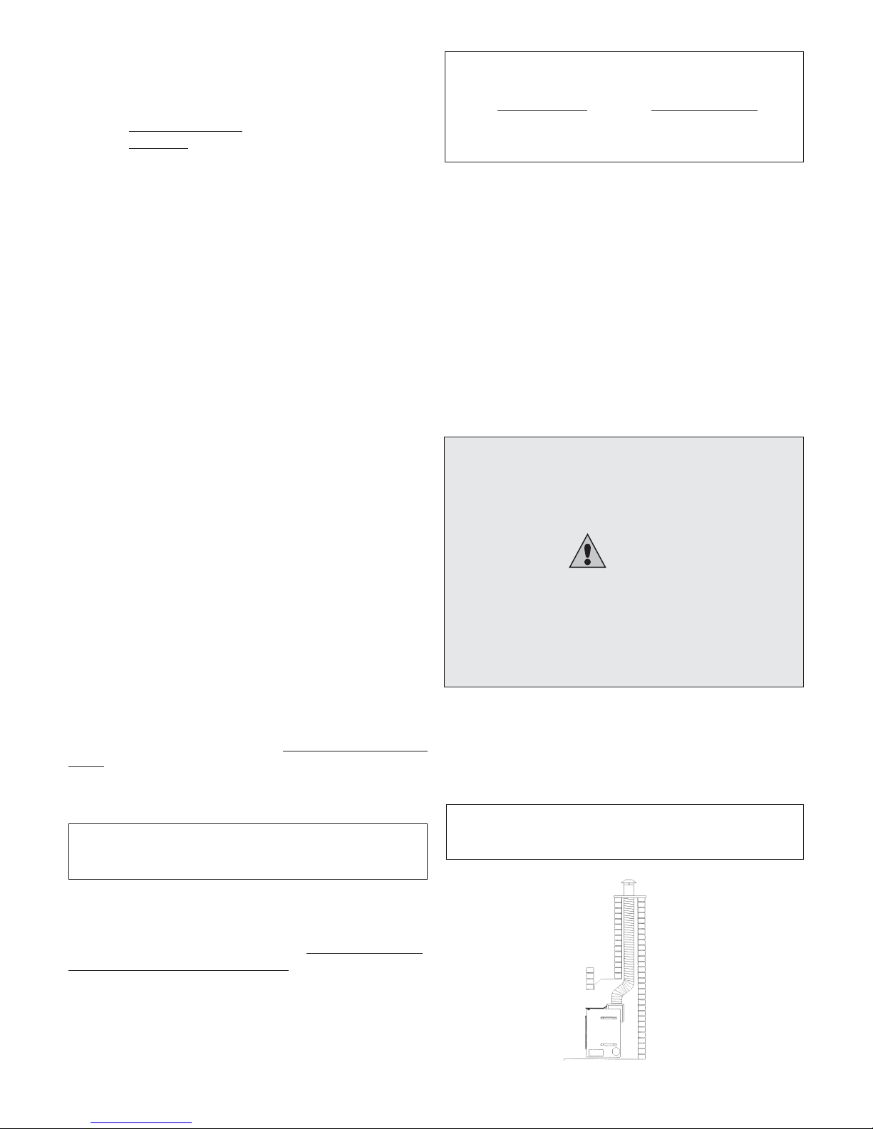
5. The draft hood is to be removed from the
fireplace insert and attached to the liner using
(
3) sheet metal screws and a clamp
(See Figure 1). It may not be necessary to
remove the draft hood if there is sufficient
space in the solid fuel fireplace to attach the
liner with the draft hood in place 24”
is required.
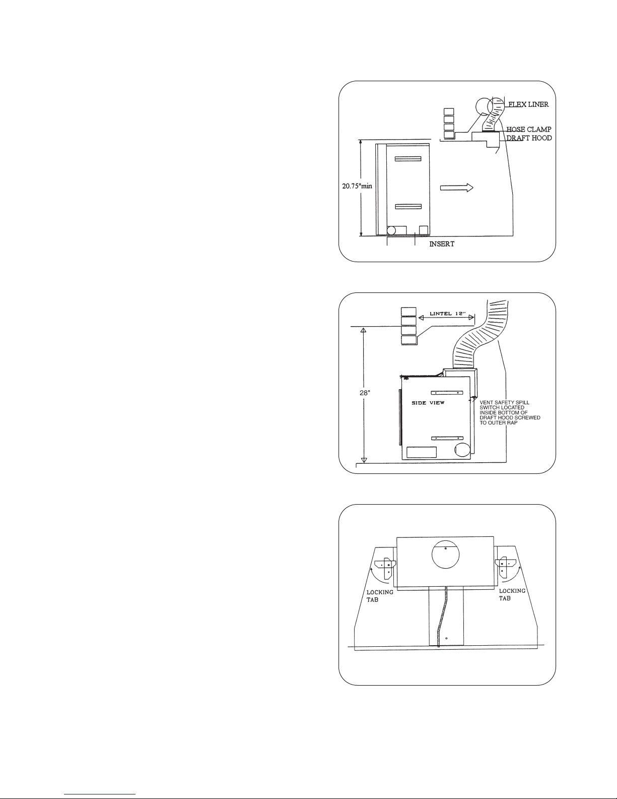
6. If the lintel is wider than 12” (305mm) then
the height of the solid fuel fireplace must be
at least 28” (711mm) to allow for an offset
elbow. (See Figure 2). If providing an
offset, do not collapse the flex pipe. This
will restrict the vent and cause a red flame
which will produce soot on glass.
7. If however the draft hood must be removed
then it must first be attached to the liner using
four (4) sheet metal screws and a clamp. The
fireplace insert can then be slid into place and
the draft hood should be located so that the
screw on the locating bracket mates with the
hole on the top centre front of the insert. The
locating bracket should be pulled as far
forward as it will go and be bolted into place
(a flashlight should be used to confirm that
the draft hood is flat on the top of the unit).
Once the draft hood is in place a long screw
driver or piece of rod must be used to rotate
the locking brackets so that the lock over top
the flanges on the side of the draft hood.
(See Figure 3)
(Figure 1)
(Figure 2)
(Figure 3)
Page 10

10
8. INSTALLATION
NOTE: INSTALLATION AND REPAIR SHOULD BE
PERFORMED BY A QUALIFIED SERVICE
PERSON. THE APPLIANCE SHOULD BE
INSPECTED BEFORE USE AND AT LEAST
ANNUALLY BY A PROFESSIONAL SERVICE
PERSON. MORE FREQUENT CLEANING MA Y BE
REQUIRED DUE TO EXCESSIVE LINT FROM
CARPETING, ETC. IT IS IMPERATIVE THAT THE
CONTROL COMPARTMENT, BURNING AND
CIRCULATING AIR PASSAGEWAYS OF THE
APPLIANCE BE KEPT CLEAN.
Install the fireplace insert in the following order:
1. Clean and inspect chimney.
2. Plan layout of gas line.
3. Plan layout of electrical.
4. Install the chimney liner as instructed in
SECTION
9.
5. Clean out and vacuum the solid fuel fireplace.
Make sure that the fireplace is completely
cool and has not been used for a few days.
6. Make sure that the solid fuel fireplace base is
level and if not make any necessary adjustments.
7. Slide unit into place attaching draft hood and or
chimney liner as required.
8. Hook up gas line.
9. Hook up electrical.
10. Remove glass by removing two screws behind
upper grill and lifting door off bottom door retainer
(glass is very fragile).
11. Log Installation:
- Remove logs from carton (4) and
inspect.
- Install as per Log Placement Guidelines
and set ups.
- Purge lines and test pilot operation.
12. Ember Kit Instructions:
Spread supplied rock evenly on the bottom of the
fireplace (DO NOT PLACE ROCK ON BURNERS), next tear ember wool into small thin pieces
and place evenly over front burner .
13. Re-install the glass door.
14. Check for correct operation
(See SECTION
10)
15. Install Surround and Grills as per
instructions.
16. Gas fired appliances may be used only for sup-
plemental heat and/or decorative purposes and
under no circumstances shall they provide a primary heat source.
(Figure 4)
NOTE: DO NOT BLOCK THE SIDES OR
TOP OF THE APPLIANCE AS THIS WILL AFFECT
THE PROPER AND SAFE
OPERATION OF THE UNIT.
C5 Log
Page 11

11
C5 or F5 Parts
Burner
Step 1: Break ember wool into thumbnail
size pieces. Place glowing embers evenly on
to the front burner tube as shown.
Step 2: Place Log #1 on burner as shown
and pull forward to the grate bars. Place log
#2 on rear log holder and center it.
Step 3: Place Log #3 onto the notched areas
as shown. Place Log #4 onto the notched
areas as shown. (Refer to step 2 for notched
area locations).
Step 4: Place lava rock around the sides and
the front of the burner as shown. Sprinkle vermiculite over top of the lava rock as shown.
(Do not place lava rock or vermiculite on the
burner tube areas).
LOGC5 OR LOGF5 PLACEMENT GUIDE
Page 12

12
Log C6 Parts List
Burner
Step 1: Place Log #1 on rear log holder, center it, and push back. Place Log #2 against
the left burner mount and back against the
ember plate log stop as shown. (Log must not
impinge on main flame pattern).
Step 3: Place Log #5 on the notched locations of Log #4. (Refer to step 2 for Log #5
notch locations). Fill the exposed areas of the
ember plates and front burner tube with
ember rocks. (Do not place ember rocks on
rear burner tube).
Step 4: Place lava rock around the sides and
front of the burner. Sprinkle the vermiculite
over top of the lava rock. (Do not place lava
rock and vermiculite on burner or ember
plates).
Step 2: Place Log #3 onto the left notch of
Log #1 and against the left grate bar as
shown. Place Log #4 onto the right notch of
Log #1 and against the right grate bar as
shown.
LOGC6 PLACEMENT GUIDELINES
Page 13

13
Field Conversion for ZDV6000 - VFI25 - VFI30
C6GEK: ZDV6000 Conversion C30GEK: VFI25 & VFI30 Conversion
2 - Ember Plates 2 - Ember Plates
1 - Ember Plate Bridge 1 - Ember Plate Bridge
1 - Grate Assembly with 5/8” Bars 1 - Grate Assembly with 1/2” Bars
4 - 1/2” x 8-18 DT Screws 2 - 1/2” x 8-18 DT Screws
Tools Required: Drill, 1/8” Drill Bit, 1/4” Nut Driver Bit
Step 1: Remove existing grate bar by bending bar slightly forward and drill out rivets.
Step 2: Seal rivet holes with two supplied screws. (ZDV6000 ONLY)
Step 3: Center legs of Grate Bar on either side of burner support and fasten with supplied self drilling Screws. (Ref: 1)
Step 4: Place Ember Plates between burner tubes right and left of Burner.
NOTE: Raised flange of Ember Plates must be to back of Burner.
Step 5: Slide Ember Plate Bridge between Ember Plates. (Ref: 2)
Warning: Failure to position the parts in accordance with these diagrams or failure to use only parts
specifically approved with this appliance may result in property damage or personal injury.
Page 14

14
9. COMBUSTION AIR
Indoor combustion air must conform to the requirements
of the applicable code:
Canada Installation Code CAN/CGA-B149.1 or (USA.)
National Fuel Gas Code ANSI-Z223.1
In homes of normal construction, sufficient combustion air
can usually be obtained by air infiltration. The fireplace
insert must be installed in area that is free of excessive
dust and dirt and where ventilation is sufficient to provide
proper combustion of gas, proper venting and the
maintenance of safe operating temperatures. When
infiltration does not provide adequate air for combustion,
outside air shall be introduced as specified in the
installation codes.
The draft hood must be installed so as to be in the same
atmospheric pressure zone as the combustion air inlet to
the appliance.
To check if there is adequate air for combustion perform
the following procedure: (See Figure 5)
I. Close all windows and doors.
2. Turn all exhaust fans on high.
3. Turn on fireplace insert.
4. To check for proper draft action a draft meter
with a minimum graduation of 0.01 inches of
water column is required. The meter is to be
attached to the 1/4 inch aluminum tube
originating in the draft hood using high
temperature silicone (tubing should not be
allowed to contact glass and unit should be
allowed to run for a minimum of 10 minutes;
area of sensing tube will become quite hot).
A minimum draft pressure of .02 inches of
water column is required to ensure that there
is no spillage at the draft diverter. This
number was arrived at through testing under
various severe conditions, actual vent
pressures under normal conditions will be
much higher. A draft pressure under .02 will
indicate either a blocked vent, down draft,
adverse house de-pressurization or improper
venting.
If there is not the proper draft then provide outside air as
instructed by the applicable code.
(Figure 5)
NOTE: DO NOT OBSTRUCT FLOW TO THE FRONT OF
THE FIREPLACE AS THIS COULD AFFECT
COMBUSTION AND BE A FIRE HAZARD. FAILURE TO
DO SO COULD RESULT IN PROPERTY DAMAGE,
INJURY AND/OR LOSS OF LIFE.
10. UNIT OPERATION & CHECK-OUT
Before trying to light the unit for the first time it is advisable
to purge the gas. Once the gas line is purged it is best to
wait a few minutes with a few open windows before trying
to light the fireplace. For detailed lighting instructions see
page 27.
Start-up Instructions:
1. Turn wall switch ( or thermostat) to the off
position.
2. Turn gas valve to “PILOT” and depress.
3. Press the red spark button repeatedly until a
steady pilot flame is present.
4. Keep the “PILOT” position on the gas valve
depressed for approximately 45 seconds.
5. Turn gas valve to the on position.
Page 15

15
Sequence of operation:
1. Turn On/Off switch (or thermostat) to the
on (call for heat) position.
2 Main burner lights.
3. If blower variable speed switch is in the
“On” position then the blower will turn on
automatically once the unit is hot enough.
4. Once the On/Off switch is turned off (or
thermostat is satisfied) then the flame will
extinguish.
5. Blower will keep on running until the fire
place has cooled down.
Shut Down Instructions:
1. Turn On/Off switch (or thermostat) to the
off position.
2. Depress gas valve and turn to “OFF”
position.
11. CHECK-OUT
Once installed, the unit should be operated at least
three (3) times to ensure that all is in working order.
NOTE: MANUFACTURING OILS AND PAINT WILL
SMOKE DURING INITIAL FIRING OF APPLIANCE.
OPEN WINDOWS FOR VENTILATION.
12. UNIT ADJUSTMENT
BEFORE LEAVING, THE INSTALLER SHOULD
MAKE THE FOLLOWING CHECKS:
(a) BTU/INPUT / GAS PRESSURE
The fireplace input is marked on the Rating Plate. The
gas valve comes factory pre-set to the proper rated
pressure and adjustment should not be necessary. If
there is any question of input then it may be necessary
to check manifold pressure.
Manifold pressure on the S.I.T. Nova valve can be
measured by loosening the slotted pressure taps on
the front bottom left of the valve. (‘E’ Inlet Pressure, and
‘A’ Manifold Pressure) and connecting a manometer .
(b) MAIN BURNER / PILOT
The pilot flame size is factory set. The pilot flame
should be at least 1.5 inches (4 cm) long. The flame
should be impinging on the pilot generator. Pilot size
can be adjusted through the pilot adjust screw. If the
pilot flame is too small and can not be adjusted through
the pilot adjust screw then there is the possibility of dirt
in the pilot orifice in which case the pilot orifice should
be cleaned or replaced.
Pressure ranges are as listed below:
Gas Supply Pressure (inches w.c.)
Min Normal Max
Natural Gas 4.5 7.0 9.0
L.P. (propane) 10.8 11.0 12.0
Manifold Pressure (inches w .c. )
Normal(HI) (LOW)
Natural Gas 3.5 1.6
L.P. (Propane) 10.0 6.3
The unit as shipped is equipped for operation for 0 to
4500 ft.
The main burner should be allowed to operate for 15
to 20 minutes before making any adjustment to the unit.
The air shutter should never be closed all the way. For
Natural Gas and Liquid Propane it is recommended
that the air shutter be set to Factory Specifications.
(See Page 4).
If there is too much primary air then the flame will be
very blue with yellow tips and smaller flame height.
If there is too little primary air then the flame will be
yellow with orange/red tips on the back flames with dark
sooty elongated tips. In this condition the glass and logs
could show signs of soot accumulation within 10 to 20
minutes.
NOTE: With a properly burning flame there
will still be a certain level of sooting. It may be
necessary to clean the glass up to 3 times
during a cold season. The amount of cleaning
required depends on the amount that the fire
place is used.
Page 16

16
13. MAINTENANCE
CAUTION: Label all wires prior to disconnection
when servicing controls. Wiring errors can cause
improper and dangerous operation. Verify proper
operation after servicing.
(a) Blower
This motor has been factory oiled and under normal
operating conditions should not require oiling.
Replacement of Blower
Remove glass (two screws behind upper grill), and
remove logs. Blower access panel is visible after rear
log is removed. Remove the screws (five on top, one on
each side) and lift from tabs, blower is then assessable
for servicing. Before re-installing blower access panel,
apply a bead of sealant Millpac to the bottom edge of
panel, (this is to assure blower does not interfere with
combustion), and than secure with screws.
(b) Burner/Pilot
The burner should be periodically cleaned by removing
any ember material and wiping off and vacuuming the
burner pan. At this time it is also recommended to
check the burner for any signs of corrosion which might
impair its operation and replace it if necessary.
The pilot should also be checked for signs of proper
operation and flame.
If replacement of pilot, generator,
thermocouple is necessary replace from top and
bottom of firebox bottom.
(Reference lower diagram Page 27)
(c) Logs
CAUTION: The logs can stay hot for several
hours after the fireplace is shut off. Serious
burns could result. It is recommended that the
fireplace be turned off for several hours before
cleaning is attempted.
DO NOT wash the logs if they have any accumulation
of soot on them. Washing the logs in any sort of
solution will just cause the soot to become imbedded in
the logs surface.
The best way to clean the logs is to blow off the soot
using compressed air at high velocity. It is also effective
to use a clean soft brush in the area of soot
accumulation. Vacuuming the log with a soft brush will
also work but do not forget to carefully wash the brush
before using it on anything else. If at all possible clean
the logs outside the home away from areas you do not
wish the soot to mark.
(d) Firebox and Heat Exchanger
To clean the firebox and heat exchanger use a vacuum.
For the firebox it is recommended to use a soft brush
on the end of the vacm as not to damage any painted
surfaces. The heat exchanger may be more difficult to
clean but can still be cleaned with the combination of a
small brush and the vacuum.
(e) Glass Cleaning
It will be necessary to clean the glass periodically.
During start-up condensation will form, and cause dust
and lint to cling to the surface of the glass.
Furthermore, the initial burn cures the paint but also
leads to the deposit of a filmy residue. It is therfore recommended that the glass be cleaned two or three
times, initially, with non-abrasive common household
glass cleansers and warm water. After that, the glass
can be cleaned two or three times a season depending
on use.
WARNING Electrical Grounding Instructions
This appliance is equipped with a three prong
(grounding) plug for your protection against
shock hazard and should be plugged directly
into a properly grounded three-prong
receptacle. Do not cut or remove the
grounding prong from this.
Warning: INSURE THAT POWER IS
TURNED OFF TO THE FIREPLACE
BEFORE SERVICING.
Warning and Cautions.
• Do not clean when the glass is hot.
• Do not use abrasive cleaners.
• Using a substitute glass will void all product
warranties.
• Do not strike or abuse glass. Care must be
taken to avoid breakage of the glass.
• Do not operate this fireplace without the glass
front or with a broken glass.
Page 17

17
h) Valve and Burner Replacement
For valve replacement it is recommended that the
burner assembly be removed, this is done by removing
two 1/4” hex screws on the left and right side of the
firebox and lifting the complete burner assembly from
(the unit and replacing defective component and reinstalling. Check for gas leaks after replacing burner
assembly.
WARNING
The appliance area must be kept clear and free from
combustible materials, gasoline and other flammable
vapours and liquids.
14. BAY WINDOW INSTALLATION
Follow all installation instructions and testing of the unit
before installing Bay Window. Turn unit off and let the
unit cool down before installing.
Attach extension knobs (Hi/Lo), (On/Off) to valve. Then
slide variable speed and piezo bracket forward by
loosening screw and secure.
Attach Bay Window Assembly by inserting clips onto
bottom channel and screw into place at top door
channel.
NOTE: The Bay Window assembly replaces the upper
glass retainer provided with the original unit. Insert flat
glass retainer and tighten, making sure glass does not
fall forward.
(See Bay Window figure 6 on page 18)
Warning and Cautions.
• Do not clean when the glass is hot.
• Do not use abrasive cleaners.
• Using a substitute glass will void all product
warranties.
• Do not strike or abuse glass. Care must be
taken to avoid breakage of the glass.
• Do not operate this fireplace without the glass
front or with a broken glass.
Glass Replacement
REPLACEMENT GLASS
Only Robax ceramic or coated NeoCeram glass may
be used for replacement. The glass must be a minimum
of 5mm thick.
Removal of the Glass Door
1. Remove the door by unscrewing the two (2) top
screws of the top channel and loosening the bottom
channel.
2. Once the top of the door is unlatched, pull it out
wards and up to unlatch the bottom.
3. To re-install, place the bottom door ledge into the
lower channel assembly first. Now, swing the door
closed to seal it against the firebox cavity. Re-attach
the upper channel assembly to secure the door to the
appliance. Tighten 4 screws.
4. To replace the class, clean all gasket materials from
the door frame. Using a high heat silicone (resistant to
500º [260ºC]) apply a bead of approximately 1/32’ to
all four sides of the frame and insert the glass with a
new gasket. The door frame should be on a flat surface
with a small amount of weight pressing the glass into
the silicon. Let everythng dry for approximately 15 to 20
minutes. The door can be re-installed by following step
3.
(f) Brass Trim and Surround
All Brass and Painted surfaces should only be wiped
off with a soft non abrasive damp cloth ( a mild dish
soap can be used if necessary ).
DO NOT use brass or other metal polishes,
glass cleaners or any other abrasive cleaners
as this will mark and damage brass or painted
surfaces.
(g) Venting
Venting should be inspected yearly by a qualified
service technician and replaced if necessary . Draft
action should be tested for as outlined in Section
9 to
conform that conditions in the house have not changed
or that the vent has not become blocked or damaged.
Page 18

18
Bay Window Assembly and Parts List:
Ref. No.
Stock No. Description
1 2000-300 Bay Window Assembly
2 2000-310 Upper Brass Window Trim
3 2000-313 Grill (Bottom)
4 1001-P188SI On/Off Pilot Extension Knob
5 1001-P189SI Hi/Lo Extension Knob
6 2000-312 Side Louvers
7 2000-070 Fan/Piezo Bracket
8 5000-P025WS Extension Spring
9 Misc. #8-24 Screw
10 1000-309 Magnet
11 1001-P633SI Valve Nova LP Hi-Lo 0820633
1001-P634SI Valve Nova-NG Hi-Lo 0820634
2000-321 Glass Side - Tempered
2000-322 Glass Front - Tempered
Bay Window (Figure 6)
Page 19

19
Surround Kit Installation:
1. Before attaching surround assembly, check operation of insert and installation of draft hood and
chimney liner .
2. To assemble surround attach panel (1), (2), and (3) with (4) bolts (10/24) and star lock nuts, if
optional brass panel kit was purchased install at this time over the surround kit and than tighten
the (4) bolts to secure all panels.
3. All brass trims (4), (5) and (6) are installed with 5/16 x 6/32 self tapping screws, attach part (4),
(5) and (6) to outer edge of surround. Then place On/Off switch into slot (upper right corner) after
right trim has been attached to surround. Route wires through 3/4” grommet hole, down right side
of surround into right side of insert. A hole is provided in firebox, attach to valve at terminals TP
and TP-TH (for SIT Valve). (Refer to Wiring Diagram on Page
19)
15. Surround and Brass Trim Assembly Instructions
Page 20

20
Replacement Parts List for Surround Kits and Panel Kits
Std. Surround Large Surround
(27-3/4 x 40-1/2”) (30-3/4 x 44”)
Ref. No.
Stock No. Stock No. Description
1 2000-401 2000-421 Top Panel
2 2000-402 2000-422 Left Panel
3 2000-404 2000-423 Right Panel
4 2000-405 2000-424 Brass Top Trim
5 2000-405 2000-425 Brass Left Trim
6 2000-406 2000-426 Brass Right Trim
7 2000-407 2000-427 Brass Top Panel
8 2000-408 2000-428 Brass Left Panel
9 2000-409 2000-429 Brass Right Panel
10 1000-216 1000-216 On/Off Switch
11 1000-243 1000-243 Wire 18-I/C (105 C)
12 Misc. Misc. Screws (10/24)
13 Misc. Misc. Nuts
14 Misc. Misc. Screws Self Tapping (5/16 x 6/32)
15 Misc. Misc. 3/4” Grommet
TYPICAL VENTING DIAGRAM
Page 21

21
16. WIRING DIAGRAM - FOR SIT VALVE SYSTEM
SPILL SAFETY SWITCH - Wiring Diagram
SIT 820-639 and 820-640 True Millivolt Systems
This System does not have a thermocouple
For units with serial number greater than 13930, see 820639 - 820640 systems.
FOR SIT 820633-820634
Wiring diagram SIT 820633820634 thermocouple system
SIT 820633 - 820634 Valves
No
Thermocouple
Page 22

22
17. WIRING DIAGRAM FOR ROBERT SHAW VALVE SYSTEM
Ref. No Stock No.
Description Ref. Letter Wire Description
1 2000-083 *Valve NO Hi/Lo (760 711 454 ) A (2) Female Slip on Insulated End
2000-083P *Valve LP Hi/Lo (760 711 454 )
2 2000-080 Thermostat (F095:105/127:113) B (1) Female Slip on Insulated End
3 1000-P134WR Pilot & Bracket (E39Al) C (1) Female Slip on Insulated End
4 2000-085 Variable Speed Switch D (3) Twist Wire Connectors
5 1000-214 Piezo - Red Button E (2) Universal Bushings
6 2000-081 Blower Motor (QLN65/0024) F (1) Strain Relief Bushing
7 1000-P135WR Thermocouple (H19E924) G (1) Cord 8ft, Three Prong 115 V
8 1000-P136WR Generator (O01A-524)
1000-206 Orifice Pilot NG (F069-2060)
1000-P104WR Orifice Pilot LP (FO69-2462)
1000-216 On/Off Rocker Switch
1000-255 Orifice Burner NG #43 Rear, #49 Front
1000-255 Orifice Burner LP #54 Rear, # 62 Front
(* Valves are factory converted, specify (NG) Natural Gas, or (LP) Liquid Propane)
Page 23

23
18. ACCESSORY LIST
Stock Number Description
Log Set: (Required for each Insert)
LOGF5 Log Set - Four Piece Fibre Split Oak (F5000, ZDV6000, VF130)
LOGC5 Log Set - Four Piece Cast Split Oak (F5000, ZDV6000, VF130)
LOGC6 Log Set - Five Piece Cast Split Oak (6000 VFI30, VFI25) c/w Glowing
Ember Rock Chunks
Surround Kit (Required for each Insert)
V30S2640B Surround Deluxe - Black
V30T2640A Trim Kit - Antique Brass
V30T2640C Trim Kit - Chrome
V30T2640P Trim Kit - Polish Brass
(Size 26 13/16” High x 40 3/4” Wide)
V30S2844B Surround Large Deluxe - Black
V30T2844A Trim Kit - Antique
V30T2844C Trim Kit - Chrome
V30T2844P Trim Kit - Polish Brass
(Size 28 13/16” High x 44 3/4” Wide)
V30S2740B Surround Kit - Black
V30T2740A Trim Kit - Antique Brass
V30T2740C Trim Kit - Chrome
V30T2740P Trim Kit - Polish Brass
(Size 27 3/4” High x 40 1/2” Wide)
V30S3044B Surround Large Kit - Black
V30T3044A Trim Kit - Antique Brass
V30T3044C Trim Kit - Chrome
V30T3044P Trim Kit - Polish Brass
(Size 30 3/4” High x 44” Wide)
V2R2640 Riser for Deluxe Surround (2 1/2”) - For Use on V30S2640B or V25S264 0B
V2R2840 Riser for Deluxe Large Surround (2 1/2”) - For Use on V30S2844B
Grill Kit (Required for each Insert)
Z6GBA Grill Kit - Classic Builder Antique Brass
Z6GBC Grill Kit - Classic Builder Chrome
Z6GBP Grill Kit - Classic Builder Polish Brass
VI30GBL Grill Kit - Black
VI30GAB Grill Kit - Antique Brass
VI30GPB Grill Kit - Polish Brass
Z6GCR Grill Kit - Chrome
Bay Window Kits (Consists of Black Upper Grill and Brass Lower Grill, Three Piece Glass Viewing Area)
VI30BWAB Bay Window (as above) with Antique Brass Louvers
VI30BWCR Bay Window (as above) with Chrome Louvers
VI30BWPB Bay Window (as above) with Polish Brass Louvers
Page 24

24
Accessories - Optional
V30P2740A Panel Kit - Antique Brass (For use on V30S2740B)
V30P2740C Panel Kit - Chrome (For use on V30S2740B)
V30P2740P Panel Kit - Polish Brass (For use on V30S2740B)
V30P3044A Panel Large Kit - Antique Brass (For use on V30S3044A)
V30P3044C Panel Large Kit - Chrome (For use on V30S3044C)
V30P3044P Panel Large Kit - Polish Brass (For use on V30S3044P)
(Note panel Kits are not available for Deluxe Surrounds)
V30ADDX Arch Door Frame - Deluxe Black (352)
V30ADTH Arch Door Frame - Top Half Black (353T)
V30ADDA Arch Door Frame - Double Arch Black (354)
V30ADDD Arch Door Frame - Double Door Arch Black (355)
V30ADBL Arch Door Frame - Black (351)
VI30RL Refractory Brick Liner (3Pce.)
ZlMT Thermostat Millivolt Wall Mount
Z80PT Thermostat Programmable Digital Millivolt Wall Mount (1F80-40)
ZlRC Remote Control Millivolt (On/Off with LED) (Model I)
ZART Remote Control Thermostat Millivolt (Model K)
RMCBN Remote Control - Basic - Natural Gas (On/Off, Hi/Lo Flame Adjustment)
RMCBP Remote Control - Basic - Liquid Propane (On/Off, Hi/Lo Flame Adjustment)
DCHS Remote Control Heatshield
Venting Accessories
VI4SK25 Chimney Liner Starter Kit - (4” Diameter x 25’)
Kit Includes: Aluminum Liner 25ft, Chimney Flashing, Rain Cap,
Mortar Collar, Screws
ZDV4FP8 Flex Pipe 4” Diameter (4’ Unexpended to 8’ Expanded)
ZDV4FP20 Flex Pipe 4” Diameter (10’ Unexpended to 20’ Expanded)
ZDV4FC Flex Connector 4” Diameter
Page 25

25
19. REPLACEMENT PARTS FOR VFI30 SYSTEM #1 Old SIT System
(If Serial Number is LESS than 13436)
Valve System Parts - S.I. T .
Part Number Description
1000-P136WR Thermopile GOAI-524
1001-P035SI Electrode Sparker 915.035 SIT
1001-P129SI Thermocouple 290.129 SIT unified
1001-P157SI Orifice Pilot LP 977.157 SIT
1001-P159SI Orifice Pilot NG 977.159 SIT
1001-P508SI HT Cable 16
1001-P633SI Valve Nova LP Hi/Lo 0820633
1001-P634SI Valve Nova NG Hi/Lo 0820634
1001-P605SI Pilot Burner LP 190.605 unified SIT
1001-P606SI Pilot Burner NG 190.606 unified SIT
REPLACEMENT PARTS FOR VFI30
New Top convertible SIT System
(If Serial Number is BETWEEN than 13436 - 13930)
Valve System Parts - S.I. T .
Part Number Description
1000-P136WR Thermopile GOAI-524
1001-P069SI Electrode Sparker 915.069 TC SIT
1001-P216SI Thermocouple 290.216 TC SIT
1001-P165SI Orifice Pilot NG 977.165 TC SIT
1001-P167SI Orifice Pilot LP 977.167 TC SIT
1001-P508SI HT Cable 16
1001-P633SI Valve Nova LP Hi/Lo 0820633
1001-P634SI Valve Nova NG Hi/Lo 0820634
1001-P713SI Pilot Burner LP 199.713 TC SIT
1001-P714SI Pilot Burner NG 199.714 TC SIT
REPLACEMENT PARTS FOR VFI30
SYSTEM #3 New SIT TC True Millivolt Vented only
(If Serial Number is equal to or GREATER than 13930)
Valve System Parts - S.I. T .
Part Number Description
1000-P136WR Thermopile GOAI-524
1001-P069SI Electrode Sparker 915.069 TC SIT
1001-P165SI Orifice Pilot NG 977.165 TC SIT
1001-P167SI Orifice Pilot LP 977.167 TC SIT
1001-P639SI Valve Nova LP Hi/Lo 0820639 True MV
1001-P640SI Valve Nova NG Hi/Lo 0820640 True MV
1001-P745SI Pilot Burner LP 199.745 TC TM
1001-P746SI Pilot Burner NG 199.746 TC TM
Page 26

26
Miscellaneous Parts
1000-EMBER Glowing Ember and Slag Kit
1000-255-36 Orifice Burner NG (0 - 4500 ft)
1000-255-52 Orifice Burner LP (0 - 4500 ft)
1000-P5423WS Flat Springs - Bay Window
2000-032F Draft Hood (Assembly)
2000-079 Gasket for Flue
2000-082 Glass - Robax (Neoceram) - (28-1/4 x 13-1/4)
w/ Black edging
2000-092 Manual - VFI30
2000-095 Thermalcord - for Door
2000-BLPSI Burner Assembly (Liquid Propane) c/w Sit Valve
2000-BNGSI Burner Assembly (Natural Gas) c/w Sit Valve
3000-930 Spill Safety Switch (36T21)
C30GEK Grate & Ember Plate Kit for Field Conversion for C6 Log Set
c/w Ember Plate & Grate Bar for VFI25,VFI30
Conversion Kit (SIT Valve only)
30VFI-CKLP LP Conversion Kit
30VFI-CKNG NG Conversion Kit
Page 27

27
20. MILLIVOLT LIGHTING INSTRUCTIONS
Pilot Burner Adjustment
1.Adjust pilot screw to provide
proper sized flame.
Recommended Maximum Lead Length (Double
Wire) When Using Wall Switch or Thermostat
Wire Size Max. Length
14 GA. 100 FT.
16 GA. 64 FT.
18 GA. 40 FT.
20 GA. 25 FT.
22 GA. 16 FT.
CAUTION: DO NOT
WIRE 120 VOLT
POWER TO MILLIVOLT SWITCHES OR
THERMOSTAT.
Page 28

BASIC ONE YEAR WARRANTY
During the first year after installation, we will provide a replacement for any component part of your unit found to be defective in materials
or workmanship, including labour costs. Repair work requires prior approval by Kingsman, labour costs are based on a predetermined rate
schedule and any repair work must be done through an authorized Kingsman dealer.
LIMITED LIFETIME WARRANTY
The heat exchanger, combustion chamber and burner of every Kingsman product excluding the Outdoor Firepit are warranted against
materials or workmanship during the period the product is owned by the original owner. The part to be replaced must be returned to our
distributor in exchange for the replacement part. Any labor, material, freight and/or handling charges associated with any repair
or replacement pursuant to this Limited Lifetime Warranty will not be covered by this warranty.
GENERAL TERMS
In lieu of providing a replacement part, we may, at our option, provide the distributor's component purchase price from us or a credit equal
to the distributors component purchase price from us toward the purchase of any new unit which we distribute. If a credit is given
in lieu of a replacement part, the rating plate from the unit being replaced must be submitted on a warranty claim, and the unit being
replaced must be made available to our distributor for disposition.
In establishing the date of installation for any purpose, including determination of the starting date for the term of this Limited Lifetime
Warranty, reasonable proof of the original installation date must be presented*, otherwise the effective date will be based upon the date of
manufacture plus thirty (30) days.
We will not be responsible for and you, the user, will pay for: (a) damages caused by accident, abuse, negligence, misuse, riot, fire, flood,
or Acts of God (b) damages caused by operating the unit where there is a corrosive atmosphere containing chlorine, fluorine, or any other
damaging chemicals (other than in a normal residential environment) (c) damages caused by any unauthorized alteration or repair
of the unit affecting its stability or performance (d) damages caused by improper matching or application of the unit or the unit's components
(e) damages caused by failing to provide proper maintenance and service to the unit (f) any expenses incurred for erecting, disconnecting
or dismantling the unit (g) parts or supplies used in connection with service or maintenance (h) damage repairs, inoperation or inefficiency
resulting from faulty installation or application (i) electricity or fuel costs or any increase in electricity or fuel cost whatsoever including
additional or unusual use of supplemental electric heat.
We shall not be liable for any incidental, consequential, or special damages or expenses in connection with any use or failure of this unit.
We have not made and do not make any representation or warranty of fitness for a particular use or purpose, and there is no implied condition
of fitness for a particular use or purpose. We make no express warranties except as stated in this Limited Lifetime Warranty. No one is authorized
to change this Limited Lifetime Warranty or to create for us any other obligation or liability in connections with this unit. Any implied
warranties shall last for one year after the original installation. Some states and provinces do not allow the exclusion or limitation of incidental
or consequential damages or do not allow limitations on how long an implied warranty or condition lasts, so the above limitations or exclusions may not apply to you. The provisions of this limited warranty are in additions to and not a modification of or subtraction from any statutory warranties and other rights and remedies provided by law.
Save this certificate. It gives you specific legal rights, and you may also have other rights which may vary from state to state and province to province.
In the event your unit needs servicing, contact your dealer or contractor who installed or serviced your unit. When requesting service,
please have the model and serial number from each unit readily available. If your dealer needs assistance, the distributor is available for support
and we, in turn support the distributor's efforts.
Fill in the installation date and model and serial numbers of the unit in the space provided below and retain this limited warranty for your files.
Model No. Serial No. Date installed
Dealer or Contractor Name :
*
To receive advantage of your warranty, you must retain the original records that can establish the installation date of your unit.
LIMITED LIFETIME WARRANTY
This Limited Lifetime Warranty applies only while the unit remains at the site of the original
installation and only if the unit is installed inside the continental United States, Alaska, Hawaii,
and Canada. The warranty applies only if the unit is installed and operated in accordance
with the printed instructions and in compliance with applicable installation and building codes
and good trade practices.
The Ultimate in Design, Engineering & Quality
 Loading...