

Page 1
Installation Instructions
Model Number VB18 and VB24 Vented Gas Log
Models VB18 and VB24 Listed Cer tified for USA and Canada
Certified to: ANSI Z21.60–2003, ANSI Z21.60a–2003, ANSI Z21.60b–2004,
CSA 2.26–2004, CSA 2.26a-2003, CSA 2.26b-2004
WARNING:
Improper
installation, adjustment, alteration,
service, or maintenance can cause
injury or property damage. Refer to this
manual for correct installation and
operational procedures. For assistance
or additional information consult a
qualified installer, service agency, or the
gas supplier.
Installation and the provisions for combustion and ventilation air must conform with the National Gas and
Propane Installation Code, ANSI
Z223.1/NFPA 54 or the CSA B149.1,
Natural Gas and Propane Installation
Code.
WARNING:
These gas logs
sets are for installation in a solid fuel
burning fireplace with a working flue
and constructed of noncombustible
material.
NOTE: Solid fuels shall not be burned
in the fireplace where the logset is installed.
This appliance must be installed by a licensed plumber or gas fitter in the Commonwealth of Massachusetts and
meet the requirements of 527 CMR 30 and 248 CMR.
NOTE: Installer, leave these
instructions with the
Consumer!
WARNING:
Failure to position the parts in accordance with
these diagrams or failure to use only parts specifically approved
with this appliance may result in property damage or personal
injury.
WARNING:
This appliance and its main gas valve must be
disconnected from the gas supply piping system during any pressure
testing of that system at test pressures equal to or less that 1/2 psi
(3.5kPa). The appliance must be isolated from the gas piping system by
closing its equipment shutoff valve during any pressure testing of the gas
supply piping system at test pressures equal to or less than 1/2 psi
(3.5kPa).
INSTALLER: Leave this manual with the appliance.
CONSUMER: Retain this manual for future reference.
Read this complete manual before beginning installation.
These instructions must be kept with the unit for future reference.
FOR YOUR SAFETY
WARNING: Improper installation, adjustment, alteration,
service or maintenance can cause property damage, personal
injury or loss of life. Refer to this manual. Installation and service
must be performed by a qualified installer, service agency or the
gas supplier.
Do not store or use gasoline or other flammable vapors and liquids
in the vicinity of this or any other appliance.
What to Do If You Smell Gas
Do not try to light any appliance.
Extinguish any open flame.
Do not touch any electrical switch.
Do not use any phone in your building.
Immediately call your gas supplier from a neighbour’s phone.
If you can not reach your gas supplier, call the fire department.
Printed in Canada October 20, 2009 18VB-MAN
A Division of R-Co. Inc.
2340 Logan Avenue
Winnipeg, Manitoba, Canada R2R 2V3
Ph: (204) 632-1962
Page 2

2
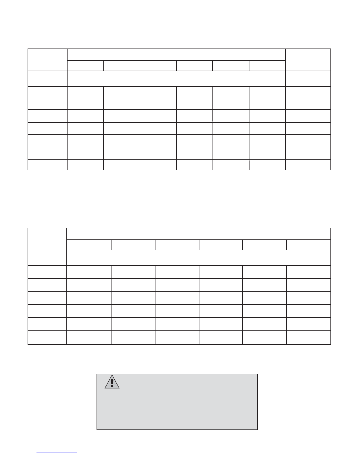
Minimum Firebox Sizing Requirements:
Burner and Log Set
18” Burner x 18” Log Set
18” Burner x 24” Log Set
24” Burner x 24” Log Set
24” Burner x 30” Log Set
Front Minimum Width
25”
29”
34”
36”
Minimum Rear Width
18”
21”
24”
26”
Depth
15”
15”
16”
17”
Height
18”
18”
18”
18”
TABLE OF CONTENTS
SECTION PAG E
Gas Specifications . . . . . . . . . . . . . . . . . . . . . . . . . . . . . . . . . . . . . . . . . . . . . . . . . . . . . . . . . . . . . . . . . . . . . . . . . . .3
Warnings Installations and Operations . . . . . . . . . . . . . . . . . . . . . . . . . . . . . . . . . . . . . . . . . . . . . . . . . . . . . . . . . . . 4
Operations and Maintenance Instructions . . . . . . . . . . . . . . . . . . . . . . . . . . . . . . . . . . . . . . . . . . . . . . . . . . . . . . . . .5
Installation Requirements for the Commonwealth of Massachusetts . . . . . . . . . . . . . . . . . . . . . . . . . . . . . . . . . . . .5
Installing . . . . . . . . . . . . . . . . . . . . . . . . . . . . . . . . . . . . . . . . . . . . . . . . . . . . . . . . . . . . . . . . . . . . . . . . . . . . . . . . . . 6
Installing Into Existing Fireplace . . . . . . . . . . . . . . . . . . . . . . . . . . . . . . . . . . . . . . . . . . . . . . . . . . . . . . . . . . . .6
Venting . . . . . . . . . . . . . . . . . . . . . . . . . . . . . . . . . . . . . . . . . . . . . . . . . . . . . . . . . . . . . . . . . . . . . . . . . . . . . . . 7
Installing Burner . . . . . . . . . . . . . . . . . . . . . . . . . . . . . . . . . . . . . . . . . . . . . . . . . . . . . . . . . . . . . . . . . . . . . . . .8
Installing Gas Line . . . . . . . . . . . . . . . . . . . . . . . . . . . . . . . . . . . . . . . . . . . . . . . . . . . . . . . . . . . . . . . . . . . . . . 8
Installing Logs . . . . . . . . . . . . . . . . . . . . . . . . . . . . . . . . . . . . . . . . . . . . . . . . . . . . . . . . . . . . . . . . . . . . .10 - 17
Lighting . . . . . . . . . . . . . . . . . . . . . . . . . . . . . . . . . . . . . . . . . . . . . . . . . . . . . . . . . . . . . . . . . . . . . . . . . . . . . . . . . .18
Cleaning And Servicing . . . . . . . . . . . . . . . . . . . . . . . . . . . . . . . . . . . . . . . . . . . . . . . . . . . . . . . . . . . . . . . . . . . . . .19
Replacement Parts List . . . . . . . . . . . . . . . . . . . . . . . . . . . . . . . . . . . . . . . . . . . . . . . . . . . . . . . . . . . . . . . . . . . . . .20
Warranty . . . . . . . . . . . . . . . . . . . . . . . . . . . . . . . . . . . . . . . . . . . . . . . . . . . . . . . . . . . . . . . . . . . . . . . . . . . . . . . . . 21
IMPORTANT INFORMATION
BEFORE INSTALLING YOUR GAS LOG SET
If the wood burning fireplace has the telltale sign of soot (blackened fascia) or smoked up when used as a wood
burning fireplace, putting a gas log set in it without rectifying the sooting issue will not solve this. There are reasons
why fireplaces soot, the damper is not open far enough, too small of flue, too large of fireplace opening, obstruction in chimney, creosite buildup, bird’s nest, negative room pressures created by insufficient outside air, exhaust
fans etc. and or log sets that are installed too close to the opening thus allowing byproducts to spill into the room,
chimney too cold, poor fireplace design. Problems with the fireplace should be rectified before operating gas log
set.
Page 3
3
GAS SPECIFICATIONS
VENTED GAS LOG SETS (Burner and Log Set are sold separately)
Burner Log Fuel BTU Manifold Orifice Primary Air Min/Max
Model Size Type Input Pressure Size Opening Inlet
Press.
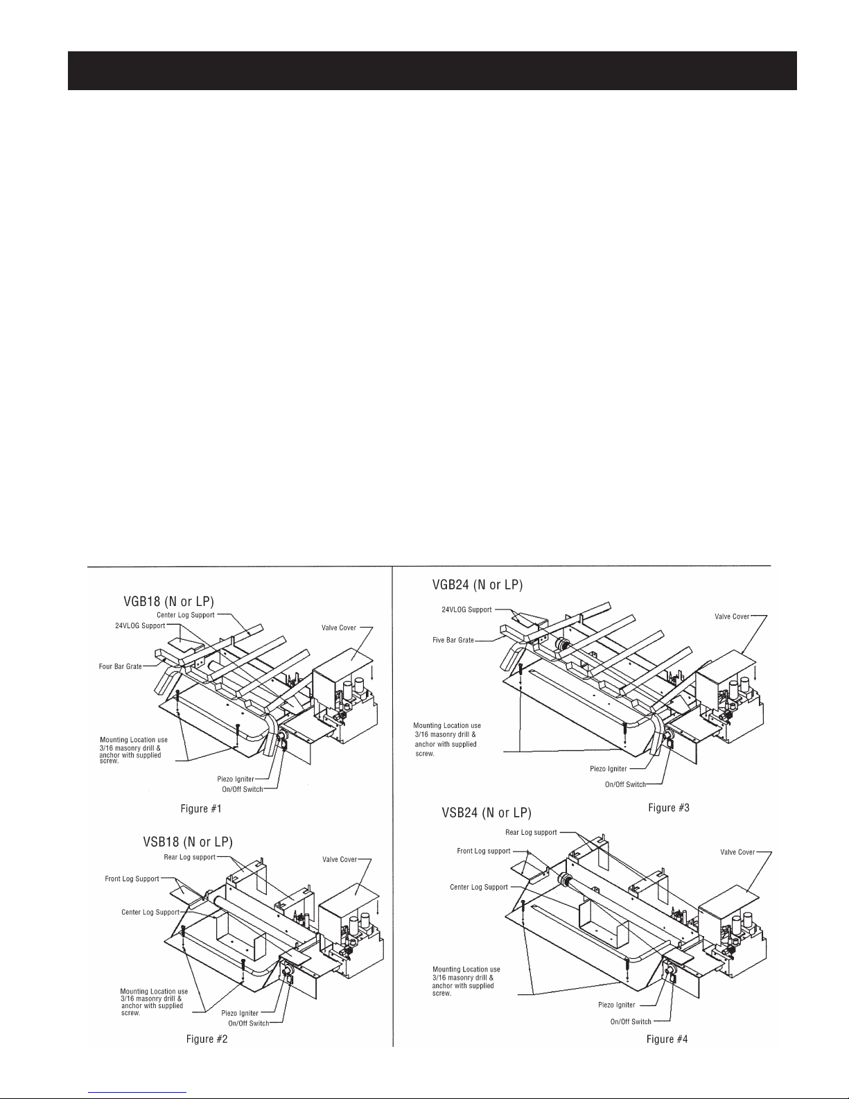
VGB18N/VSB18N 18”-24” Natural Gas 30,000 - 48,500 1.6” - 3.5” #29 Non 5.5/10”
VGB18LP/VSB18LP 18”-24” Liquid Propane 38,000 - 47,000 6.3” - 10” #47 .25” 11/13”
VGB24N/VSB24N 24”-30” Natural Gas 46,000 - 73,000 1.6” - 3.5” #20 Non 5.5/10”
VGB24LP/VSB24LP 24”-30” Liquid Propane 68,000 - 86,000 6.3” - 10” #37 .25” 11/13”
Log Set required for each burner (above)
VLOG18 Split Oak 18”
VLOG24 Reversible Charred Split or Barked Oak 24”
VLOG30 Reversible Charred Split or Barked Oak 30”
Accessories
ZIRC Remote Control – On/Off
RMCBN Remote Control for Natural Gas – On/Off, Hi/Lo Flame Adjustment
RMCBP Remote Control for Propane – On/Off, Hi/Lo Flame Adjustment
VLBIT4 Log Bit - Four Piece
VLBIT6 Log Bit - Six Piece
NOTE: Flame appearance and flame height will vary with specific installations.
Page 4

4
Warnings, Installations, and Operations
• Gas fired appliances may be used only for supplemental heat and/or decorative purposes and under no circumstances
shall they provide a primary heat source.
FOR SAFE INSTALLATION AND OPERATION OF YOUR GAS FIREPLACE PLEASE NOTE THE FOLLOWING:
1. Do not clean when the glass is hot.
2. Do not use abrasive cleaners.
3. Using a substitute glass will void all product warranties.
4. For safe operation, glass doors must be closed.
5. When purging the gas line, the glass front must be
removed.
6. Do not strike or abuse glass. Take care to avoid breakage.
7. Do not alter gas orifice.
8. No substitute materials may be used other than factory
supplied components.
9. This appliance gives off high temperatures and should be located out of heavy traffic areas and away from furniture and
draperies.
10. Children and adults should be alerted to the hazards of the high surface temperatures of this appliance and should stay
away to avoid burns or ignition of clothing.
11. Young children should be carefully supervised when they are in the same room as the appliance. Toddlers, young children
and others may be susceptible to accidental contact burns. A physical barrier is recommended if there are at risk individuals in the house. To restrict access to a fireplace or stove, install an adjustable safety gate to keep toddlers, young children
and other at risk individuals out of the room and away from hot surfaces.
12. Under no circumstances should any solid fuels (wood, paper) be used in this appliance.
13. Under no circumstances should this appliance be modified. Any parts that have to be removed for servicing should be replaced prior to operating this appliance.
14. Installation and repair should be done by a qualified service person. The appliance should be inspected before use and at
least annually by a professional service person. More frequent cleaning may be required due to excessive lint from carpeting, bedding material, et cetera. It is imperative that control compartments, burners and circulating air passageways of the
appliance be kept clean. Make sure that the gas valve and pilot light are turned off before you attempt to clean this unit.
15. Clothing or other flammable material should not be placed on or near the appliance. This appliance should not be used as
a drying rack for clothing nor should Christmas stockings or decorations be hung from it.
16. Do not use this heater if any part has been under water. Immediately call a qualified service technician to inspect the
heater and to replace any part of the control system and any gas control which has been under water.
17. Do not operate appliance unless completely installed as per installation instructions.
18. Failure to position the parts in accordance with these diagrams or failure to use only parts specifically approved with this
appliance may result in property damage or personal injury.
19. Do not operate appliance with the glass front removed, cracked or broken. Replacement of the glass should be done by a
licensed or qualified service person.
20. The front of the fireplace gives off high temperatures that could ignite combustible material which is kept close to the front
of the unit.
21. Ensure that power to the Fireplace is turned off before servicing.
22. Do not operate this Fireplace without the glass front or with a broken glass.
23. Improper installation, adjustment, alteration, service or maintenance can cause injury or property damage. Refer to the
owner’s information manual provided with this appliance. For assistance or additional information consult a qualified installer, service agency, or the gas supplier.
24. Operation of this appliance when not connected to a properly installed and maintained venting system or tampering with
the blocked vent shutoff system can result in carbon monoxide (CO) poisoning and possible death.
Installation Regulations
This gas appliance must be installed by a qualified installer in accordance with local building codes, or in the absence of local
codes, with the current CAN/CGA-B149.1 Installation Code (in Canada) or the current National Fuel Gas Code Z223.1 when installed in the United States.
This appliance, when installed, must be electrically connected and grounded in accordance with local codes, or in the absence of
local codes, with the current CSA C22.1 Canadian Electrical Code or with the national Electrical Code; ANSI/NFPA 70-1987 when
installed in the United States.
Warning
Page 5
5
• If the factory-built fireplace has no gas access hole(s) provided, an access hole of 1.5in [37.5mm] or less may be drilled
through the lower sides or bottom of the firebox in a proper workmanship like manner. This access hole must be plugged with
non-combustible insulation after the gas supply line has been installed.
• Cutting any sheet-metal parts of the fireplace, in which the gas fireplace insert is to be installed, is prohibited.
• This appliance must not be connected to a chimney flue serving a separate solid-fuel burning appliance.
• Installer must mechanically attach the supplied label to the inside of the fireplace into which the gas fireplace insert is installed.
NOTE: It is recommended that a Carbon Monoxide (CO) Detector be installed in or near bedrooms and on all levels of your
home. Place a detector about 15ft [4.5m] outside the room that houses your gas appliance.
Certified for installation in a bedroom or bed/sitting room. In Canada must be installed with listed millivolt thermostat. In USA see local codes.
For safe installation and operation note the following:
• The Burner/Log Assembly has been engineered and permanently adjusted for proper flame control.
• Periodically remove the logs from the grate assembly and vacuum any loose particles from the grate and burner areas. See
Log Placement page to remove logs. Vacuum burner parts and replace logs.
• Label all wires prior to disconnection when servicing controls. Wiring errors can cause improper and dangerous operation.
Verify proper operation after servicing.
In the Commonwealth of Massachusetts, the installer or service agent shall be a plumber or gas fitter licensed by the Commonwealth.
When installed in the Commonwealth of Massachusetts or where applicable codes; the unit shall be installed with a CO detector per the requirements listed below.
1. For direct-vent appliances, mechanical-vent heating appliances or domestic hot water equipment, where the bottom of the
vent terminal and the air intake is installed below four feet above grade the following requirements must be satisfied:
A. If there is not one already present, on each floor level where there are bedroom(s), a carbon monoxide detector and
alarm shall be placed in the living area outside the bedroom(s). The carbon monoxide detector shall comply with NFPA
720 (2005 Edition).
B. A carbon monoxide detector shall be located in the room that houses the appliance or equipment and shall:
• Be powered by the same electrical circuit as the appliance or equipment such that only one service switch services
both the appliance and the carbon monoxide detector;
• Have battery back-up power;
• Meet ANSI./UL 2034 Standards and comply with NFPA 720 (2005 Edition); and
• Have been approved and listed by a Nationally Recognized Testing Laboratory as recognized under 527 CMR.
C. A Product-approved vent terminal must be used, and if applicable, a Product-approved air intake must be used.
Installation shall be in strict compliance with the manufacturer’s instructions. A copy of the installation instructions shall
remain with the appliance or equipment at the completion of the installation.
D. A metal or plastic identification plate shall be mounted at the exterior of the building, four feet directly above the loca
tion of vent terminal. The plate shall be of sufficient size to be easily read from a distance of eight feet away, and read
“Gas Vent Directly Below”.
2. For direct-vent appliances, mechanical-vent heating appliances or domestic hot water equipment where the bottom of the
vent terminal and the air intake is installed above four feet above grade the following requirements must be satisfied:
A . If there is not one already present, on each floor level where there are bedroom(s), a carbon monoxide detector and
alarm shall be placed in the living area outside the bedroom(s). The carbon monoxide detector shall comply with NFPA
720 (2005 Edition).
B. A carbon monoxide detector shall:
• Be located in the room that houses the appliance or equipment;
• Be either hard-wired or battery powered or both; and
• Shall comply with NFPA 720 (2005 Edition).
A Product-approved vent terminal must be used, and if applicable, a Product-approved air intake must be used. Installation shall
be in strict compliance with the manufacturer instructions. A copy of the installation instructions shall remain with the appliance or
equipment at the completion of the installation.
For the state of Massachusetts a T-handle gas shut-off valve
must be used on a gas appliance. This T-handle gas shut-off
valve must be listed and approved by the state of Massachusetts. This is in reference to the state of Massachusetts state code
CMR238.
Operations and Maintenance Instructions
Installation Requirements for the Commonwealth of Massachusetts
Warning: This fireplace has been converted for use with a gas fireplace insert only and cannot be used
for burning wood or solid fuels unless all original parts have been replaced, and the fireplace re-approved by
the authority having jurisdiction.
Page 6
INSTALLING
INSTALLATION OF BURNER INTO
EXISTING FIREPLACE
NOTE: Installed only in a solid fuel burning fireplace with
a working flue and constructed of non-combustible material. See chart on following page for minimum permanent
flue opening based on KBTU/HR and chimney height.
The damper must be secured so the minimum flue opening will be maintained at all times.
Warning:
Before installing in a solid fuel
burning fireplace, the chimney flue and firebox must
be cleaned of soot, creosote, ashes, and loose paint
by a qualified chimney cleaner. Creosote may ignite
when heated to a high temperature. Have chimney
flue inspected for damage. If flue system is
damaged, do not install the unit.
Warning:
Seal any fresh air vents or ash
cleanout doors located on the floor or wall of
fireplace. If this is not done, drafting may result
causing pilot outage or sooting. Use a heat-resistant
sealant. Do not seal chimney flue damper.
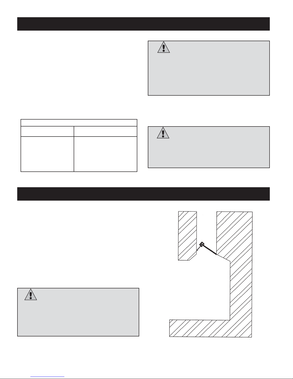
INSTALLING - DAMPER STOP
A damper stop is provided with vented log set. The
damper stop must be installed as shown in the diagram, damper stop is for minimum flue opening.
If the clamp does not fit or provide the minimum permanent flue opening as per charts, have the damper
cut or drilled to provide minimum permanent opening
or install a permanent stop.
Warning:
Installation of vented gas logs in
the Commonwealth of Massachusetts requires the
vent damper be permanently removed or welded in
the full open position. Vented gas logs can not be
installed in a bedroom or bathroom in the
Commonwealth of Massachusetts
6
Area of Various Standard Round Flues
Diameter (inside) Area (square inches)
5” 20 square inches
6” 29 square inches
7" 39 square inches
8” 51 square inches
Page 7
7
(A) - For Factory Built Fireplaces Free Opening Area of Chimney
Damper For Venting Combustion Products From Decorative Appliances
For Installation In Solid Fuel Burning Fireplaces
Appliance Input Rate (kBTU/hr)
40 50 60 70 80 90
Chimney Minimum Opening** (sq. in.) Max.
Height* (ft) input***
10 22.1 28.3 35.3 44.2 __ __ 77.6
15 17.3 21.2 26.4 32.2 28.5 45.4 98.2
20 14.5 18.1 22.1 26.4 31.2 37.4 114.2
25 12.6 15.9 18.1 22.9 27.3 31.2 121.0
30 11.3 14.5 17.3 20.4 24.6 28.3 130.1
35 10.8 13.2 15.9 18.9 22.1 25.5 141.2
40 10.2 12.6 15.2 18.1 20.4 23.8 158.5
(B) - For Masonry Built Fireplaces Free Opening Area of Chimney
Damper For Venting Combustion Products From Decorative Appliances
For Installation In Solid Fuel Burning Fireplaces
Warning:
Check the fireplace for proper venting,
use a match or smoke pen, if any spillage is noted then
the Damper shall be opened until no spillage occurs. If a
proper draft can not be obtained, contact your dealer for
assistance.
* Height is from hearth to top of chimney and the minimum height is 10 feet.
** Chart shows minimum opening (sq. in.) for the given height and input rate.
*** Column marked “Max. Input” corresponds to the maximum allowable input rate (kBTU/hr) for the given height.
Appliance Input Rate (kBTU/hr)
40 50 60 70 80 90
Chimney Minimum Opening** (sq. in.)
Height* (ft)
6 33.8 41.7 49.2 56.6 64.0 71.4
8 31.2 38.7 45.5 52.4 59.7 66.9
10 28.7 35.2 41.7 48.5 54.3 60.2
15 26.1 32.0 37.7 43.2 48.8 54.1
20 23.7 28.8 34.4 39.8 44.4 49.1
30 21.6 26.5 31.2 35.9 40.3 44.5
* Height is from hearth to top of chimney and the minimum height is 6 feet.
** Chart shows minimum opening (sq. in.) for the given height and input rate.
Page 8

8
INSTALLING – Gas Line
INSTALLING GAS LINE
Early signs of carbon monoxide poisoning resemble the
flu, with headaches, dizziness, and / or nausea. If you
have these signs, the heater may not be working properly. Get fresh air at once! Turn off gas appliance. Have
appliance serviced. Some people (such as pregnant
women, persons with heart or lung disease, persons with
anemia and those at high altitudes) are more affected by
carbon monoxide than others. Make certain you read and
understand all warnings. Place Burner Base / Grate Assembly in center of firebox and connect flexible gas line to
incoming black iron pipe gas line.
Do not connect appliance before pressure testing gas
piping. Damage to gas valve may result and an unsafe
condition may be caused.
Prepare incoming black iron gas line with Teflon tape or
pipe joint compound (check with local codes about the
use of Teflon tape). Compounds used on threaded joints
of gas piping shall be resistant to the action of Liquefied
Petroleum (LP or Propane) and should be applied lightly
to ensure excess sealant does not enter the gas line.
Complete your gas installation by connecting incoming
gas line to regulator. Secure all joints tightly with wrench
but do not over-tighten. If a flexible gas line is used,
take care not to kink connector. The burner pressure is
controlled by the regulator. Check pressure at the
Warning:
Installation and repair should be
done by a qualified service person well trained in
the installation of such appliances. You will also
need a building permit from your local Building
Commissioner before installing this appliance,
otherwise your insurance company may not cover
this appliance.
Warning:
CARBON MONOXIDE
POISONING MAY LEAD TO DEATH!
Warning:
Any changes to this heater or its
controls can be dangerous.
INSTALLING – BURNER
INSTALLING BURNER TO FIREBOX:
1. Position Grate/Burner assembly into solid fuel firebox
with the front burner located directly under the opening
for the best flame appearance. (DO NOT have any of
the burner assembly outside the firebox.)
2. Drill two 3/16” diameter holes as indicated in the diagram, approximately 1 1/2” deep.
3. Anchor the burner assembly to the floor using the 2
screws provided.
For the state of Massachusetts a T-handle gas shut-
off valve must be used on a gas appliance. This Thandle gas shut-off valve must be listed and approved
by the state of Massachusetts. This is in reference to
the state of Massachusetts state code CMR238.
cont’d on page 9
Page 9

99
Warning:
All gas piping and connections
must be tested for leaks after installation is
completed. To test, turn gas valve on, then apply a
soap and water solution to all connections and joints.
If bubbles appear, leak can be detected and
corrected. Never use an open flame for leak
testing. Never operate any appliance if a leak is
detected!
Warning:
Use new black pipe only. Internally
tinned copper tubing can be used in some areas
when permitted by local codes. Only use pipe of
1/2” or greater diameter to allow full gas volume to
heater. Excessive pressure loss will occur if the pipe
is too small.
A manual shutoff valve, union and plugged
1
⁄8” NPT
pressure tap pointer must be installed upstream of
the heater.
A sediment trap must be installed upstream of the
heater to prevent moisture and contaminants from
passing through the pipe to the heater controls and
burners. Failure to do so could prevent the heater
from operating reliably.
INSTALLING – Gas Line Cont.
pressure test point, which is located on the front of the
gas control. Make sure that the pressure tap is completely closed after checking gas pressure. The pressure should be checked with the appliance burning and
the control set on high.
IMPORTANT: Loosen the pipe adapter on the flex tube
before installing to the system piping.
CHECK GAS TYPE: The gas supply must be the
same as stated on the heater’s rating plate. If the gas
supply is different, Do Not Install the heater. Contact
your dealer for the correct model.
Warning:
A qualified gas appliance installer
must connect the fireplace to the gas supply.
Consult all local codes.
Warning:
Any safety screen or guard
removed for servicing an appliance must be
replaced prior to operating the heater.
Page 10

10
LOG INSTALLATION - VLOG18/VGB18
Step 2
Step 4
Step 5
Step 3
Place crossover logs #3 and #4 on top as shown.
Place crossover logs #5 and #6 on tops as shown.
Place silica sand (NG only) or 1/4” small rock
(LP only) inside and in front of burner pan. Place
1” large rock inside, in front, and around the
sides of the pan. Place rock wool in front of the
grate bar. Sprinkle vermiculite over top of lava
rock and rock wool.
Place rear log #1 on the back of the grate & pull
forward toward guide pins. Place front log #2 on
the front of the grate & pull forward.
Step 1
Page 11

1111
LOG INSTALLATION - VLOG18/VSB18
Step 2
Step 4 Step 5
Step 3
Place crossover logs #3 and #4 on top as shown.
Place crossover logs #5 and #6 on tops as shown.
Place silica sand (NG only) or 1/4” small rock (LP
only) inside and in front of burner pan. Place 1” large
rock inside, in front, and around the sides of the pan.
Place rock wool in front of center log support as
shown. Sprinkle vermiculite over top of lava rock and
rock wool.
Place rear log #1 on the rear log supports. Place
front log #2 over top front and center log support.
Step 1
Page 12

1212
LOG INSTALLATION - VLOG24/VGB18
Step 2
Step 4 Step 5
Step 3
Place crossover logs #4 and #5 on top as shown.
Place crossover logs #6, #7 and #8 on top as shown.
Place silica sand (NG only) or 1/4” small rock (LP only)
inside and in front of burner pan. Place 1” large rock inside, in front, and around the sides of the pan. Place
rock wool in front of the grate bar. Sprinkle vermiculite
over top of lava rock and rock wool.
Place rear log #1 on the back of the grate & pull forward toward guide pins. Place front logs #2 and #3 on
the front of the grate & pull forward.
This log set has the option to be reversed from a split look to a bark look or vice versa by turning the front logs and
crossover logs. Rear log #1 is not reversible.
Step 1
Page 13

1313
LOG INSTALLATION - VLOG24/VSB18
Step 2
Step 4 Step 5
Step 3
Place crossover logs #4 and #5 on top as shown.
Place crossover logs #6, #7 and #8 on top as shown.
Place silica sand (NG only) or 1/4” small rock (LP only)
inside and in front of burner pan. Place 1” large rock inside, in front, and around the sides of the pan. Place
rock wool in front of center log support as shown.
Sprinkle vermiculite over top of lava rock and rock
wool.
Place rear log #1 on the rear log support. Place front
logs #2 and #3 on the front and center log support.
This log set has the option to be reversed from a split look to a bark look or vice versa by turning the front logs and
crossover logs. Rear log #1 is not reversible.
Step 1
Page 14

1414
LOG INSTALLATION - VLOG24/VGB24
Step 2
Step 4 Step 5
Step 3
Place crossover logs #4 and #5 on top as shown.
Place crossover logs #6, #7 and #8 on top as shown.
Place silica sand (NG only) or 1/4” small rock (LP only)
inside and in front of burner pan. Place 1” large rock inside, in front, and around the sides of the pan. Place
rock wool inside the middle of the pan and also in front
of the grate bar. Sprinkle vermiculite over top of lava
rock and rock wool.
Place rear log #1 on the back of the grate & pull forward toward guide pins. Place front logs #2 and #3 on
the front of the grate & pull forward.
This log set has the option to be reversed from a split look to a bark look or vice versa by turning the front logs and
crossover logs. Rear log #1 is not reversible.
Step 1
Page 15

1515
LOG INSTALLATION - VLOG24/VSB24
Step 2
Step 4 Step 5
Step 3
Place crossover logs #4 and #5 on top as shown.
Place crossover logs #6, #7 and #8 on top as shown.
Place silica sand (NG only) or 1/4” small rock (LP only)
inside and in front of burner pan. Place 1” large rock inside, in front, and around the sides of the pan. Place
rock wool in front of center log support as shown.
Sprinkle vermiculite over top of lava rock and rock
wool.
Place rear log #1 on rear log supports. Place front logs
#2 and #3 on the front and center log supports as
shown.
This log set has the option to be reversed from a split look to a bark look or vice versa by turning the front logs and
crossover logs. Rear log #1 is not reversible.
Step 1
Page 16

1616
LOG INSTALLATION - VLOG30/VGB24
Step 2
Step 1
Step 4 Step 5
Step 3
Place crossover logs #4 and #5 on top as shown.
Place crossover logs #6, #7 and #8 on top as shown.
Place silica sand (NG only) or 1/4” small rock (LP only)
inside and in front of burner pan. Place 1” large rock inside, in front, and around the sides of the pan. Place
rock wool inside the middle of the pan and in front of
the grate bar.. Sprinkle vermiculite over top of lava rock
and rock wool.
Place rear log #1 on back of grate and pull forward toward guide pins. Place front logs #2 and #3 on the front
of the grate and pull forward.
This log set has the option to be reversed from a split look to a bark look or vice versa by turning the front logs and
crossover logs. Rear log #1 is not reversible.
Page 17

1717
LOG INSTALLATION - VLOG30/VSB24
Step 2
Step 1
Step 4 Step 5
Step 3
Place crossover logs #4 and #5 on top as shown.
Place crossover logs #6, #7 and #8 on top as shown.
Place silica sand (NG only) or 1/4” small rock (LP only)
inside and in front of burner pan. Place 1” large rock inside, in front, and around the sides of the pan. Place
rock wool in front of center log support as shown.
Sprinkle vermiculite over top of lava rock and rock
wool.
Place rear log #1 on rear log support. Place front logs
#2 and #3 on front and center log support as shown.
This log set has the option to be reversed from a split look to a bark look or vice versa by turning the front logs and
crossover logs. Rear log #1 is not reversible.
Page 18

1818
LIGHTING
FIGURE 12 – Millivolt Models
NOTE: Thermostat not to be used on a vented
gas log set.
Warning:
If you do not follow these instructions
exactly, a fire or explosion may result causing property
damage, personal injury or loss of life.
Page 19

19
CLEANING AND SERVICING
CLEANING AND SERVICING OF BURNER AND PILOT
It is recommended to annually inspect and clean the unit to prevent malfunction and / or sooting. This
operation should be performed by your dealer or a qualified technician.
Remove log set, handling carefully by holding gently at each end. (Refer to
Log Placement,
page 10.) Gloves are
recommended to prevent skin irritation from ceramic.
Annual Cleaning / Inspection
• Do not use cleaning fluids to clean logs or any part of
the heater.
• Use a soft bristle brush or a vacuum with brush
attachment.
• Vacuum loose particles and dust from burner ports,
valve and blower compartments.
• Vacuum any accumulation of lint from primary mixing hole. Propane Only.
• Inspect pilot for operation, accumulation of lint at the air inlet holes.
• Verify flame pattern and log placement for proper operation.
• Verify that all ports ignite and cross over smoothly from rear
to front burner.
CLEANING LOGS
Turn gas supply off. Allow logs to cool. Remove logs, handle with care. Use a very soft bristle brush buildup on logs. Do not use any liquid cleaners, this will embed logs with soot.
FIGURE 11 – Standing Pilot
Warning:
Turn off heater and allow to cool
before cleaning. Only a qualified service technician
should service and repair appliance.
Page 20

20
REPLACEMENT PARTS LIST
Item No. Parts No. Description Fits
1a 18LGR-PAN Burner Pan W/Burner VSB18/VGB18
1b 24LGR-PAN Burner Pan W/Burner VSB24/VGB24
2a 18LGR-GRATE Four Bar Grate Assembly VGB18
2b 24LGR-GRATE Five Bar Grate Assembly VGB24
3 24LGR-CVR Valve Cover Assembly (3PCS) All
3a 24LGR-107 Valve Cover Body All
3b 24LGR-108 Valve Cover Top All
3c 24LGR-109 Valve Cover Front All
4a 1000-214 Piezo Igniter All
4b 1000-215 Pal Nut All
5 1000-216 Rocker Switch All
6 24LGR-114 Center Log Support VSB18 / VSB24
7 24LGR-113 Back Log Support VSB18(2pcs) VSB24(3pcs)
8 24LGR-106 Left Log Support VSB18/VSB24
9 24LGR-106R Right Log Support VSB18/VSB24
10 24LGR-110 Left Log Support VGB18/VGB24
11 24LGR-110R Right Log Support VGB18/VGB24
12 24LGR-111 Pilot Bracket All Part of 18LGR-PAN/24LGR-PAN
13 1001-P069SI TC – Electrode Cable & Sparker 915.069 O .075
1001-P165SI TC – Orifice Pilot NG 977.165 #51 (Standard)
1001-P166SI TC – Orifice Pilot NG 977.166 #62 (Larger)
1001-P167SI TC – Orifice Pilot LP 977.167 #30 (Standard)
1001-P168SI TC – Orifice Pilot LP 977.168 #35 (Larger)
1001-P280SI TC Tubing With Fitting 1/8 2.182.280
13a 1001-P746SI TC - Pilot Burner (Assembled) NG 199.746 VSB18N/VGB18N- VSB24N/VGB24N
13b 1001-P745SI TC - Pilot Burner (Assembled) LP 199.745 VSB18LP/VGB18LP VSB24LP/VGB24LP
14a 24LGR-P119DC-N MP119-DC 3/8" x 1/2" Reducing Coupler VSB18N/VGB18N VSB24N/VGB24N
14b 24LGR-P119DC-LP MP119-DC 3/8" x 1/2" Reducing Coupler VSB18LP/VGB18LP VSB24LP/VGB24LP
15a 24LGR-PG0972-29 Burner Orifice Natural Gas VSB18N/VGB18N
15b 24LGR-PG0972-47 Burner Orifice Propane VSB18LP/VGB18LP
15c 24LGR-PG0972-20 Burner Orifice Natural Gas VSB24N/VGB24N
15d 24LGR-PG0972-37 Burner Orifice Propane VSB24LP/VGB24LP
16 24LGR-P40330 Brass Nipple 3/8 Hex with Internal Thread All
17 24LGR-P115C Brass 115-C 3/8 x 90 Degree Street Elbow All
18a 1001-P640SI Valve 820.640 NG HI/LO VSB18N/VGB18N VSB24N/VGB24N
18b 1001-P639SI Valve 820.639 LP HI/LO VSB18LP/VGB18LP VSB24LP/VGB24LP
19 24LGR-P108D MP108-D Cap 1/2” All
20a 24LGR-P113D14 MP113-D14 Nipple 1/2” x 14” – VB18 Part of 18LGR-PAN
20b 24LGR-P113D18 MP113-D14 Nipple 1/2” x 18” – VB24 Part of 24LGR-PAN
ADDITIONAL BURNER COMPONENTS
24LGR-PBC200 Damper Clamp
24LGR-CINS Black Cinders 1/4” (Small) – For Propane Use Only
24LGR-CINL Black Embers 1”
24LGR-EMBER Ember Insulation
24LGR-SAND Silica Sand – For Natural Gas Use Only
24LGR-VERM Vermiculite
Accessories
Z1RC Remote Control – ON/Off
RMCBN Remote Control for Natural Gas – On/Off, Hi/Lo Flame Adjustment
RMCBP Remote Control for Propane – On/Off, Hi/Lo Flame Adjustment
Page 21

21
BASIC ONE YEAR WARRANTY
During the first year after installation, we will provide a replacement for any component part of your unit found to be defective in materials
or workmanship, including labour costs. Repair work requires prior approval by Kingsman, labour costs are based on a predetermined rate schedule and any repair work must be done through an authorized Kingsman dealer.
LIMITED WARRANTY
The burner is warrantied for three years against materials or workmanship during the period the product is owned by the original owner. The
part to be replaced must be returned to our distributor in exchange for the replacement part. Any labor, material, freight and/or handling charges
associated with any repair or replacement pursuant to this Limited Warranty will not be covered by this warranty.
GENERAL TERMS
In lieu of providing a replacement part, we may, at our option, provide the distributor's component purchase price from us or a credit equal
to the distributors component purchase price from us toward the purchase of any new unit which we distribute. If a credit is given
in lieu of a replacement part, the rating plate from the unit being replaced must be submitted on a warranty claim, and the unit being
replaced must be made available to our distributor for disposition.
In establishing the date of installation for any purpose, including determination of the starting date for the term of this Limited Warranty, reasonable proof of the original installation date must be presented*, otherwise the effective date will be based upon the date of manufacture plus
thirty (30) days.
We will not be responsible for and you, the user, will pay for: (a) damages caused by accident, abuse, negligence, misuse, riot, fire, flood,
or Acts of God (b) damages caused by operating the unit where there is a corrosive atmosphere containing chlorine, fluorine, or any other
damaging chemicals (other than in a normal residential environment) (c) damages caused by any unauthorized alteration or repair
of the unit affecting its stability or performance (d) damages caused by improper matching or application of the unit or the unit's components
(e) damages caused by failing to provide proper maintenance and service to the unit (f) any expenses incurred for erecting, disconnecting
or dismantling the unit (g) parts or supplies used in connection with service or maintenance (h) damage repairs, inoperation or inefficiency resulting from faulty installation or application (i) electricity or fuel costs or any increase in electricity or fuel cost whatsoever including
additional or unusual use of supplemental electric heat.
We shall not be liable for any incidental, consequential, or special damages or expenses in connection with any use or failure of this unit.
We have not made and do not make any representation or warranty of fitness for a particular use or purpose, and there is no implied condition
of fitness for a particular use or purpose. We make no express warranties except as stated in this Limited Warranty. No one is authorized to change
this Limited Warranty or to create for us any other obligation or liability in connections with this unit. Any implied
warranties shall last for one year after the original installation. Some states and provinces do not allow the exclusion or limitation of incidental
or consequential damages or do not allow limitations on how long an implied warranty or condition lasts, so the above limitations or exclusions
may not apply to you. The provisions of this limited warranty are in additions to and not a modification of or subtraction from any statutory warranties and other rights and remedies provided by law.
Save this certificate. It gives you specific legal rights, and you may also have other rights which may vary from state to state and province to province.
In the event your unit needs servicing, contact your dealer or contractor who installed or serviced your unit. When requesting service,
please have the model and serial number from each unit readily available. If your dealer needs assistance, the distributor is available for support
and we, in turn support the distributor's efforts.
Fill in the installation date and model and serial numbers of the unit in the space provided below and retain this limited warranty for your files.
Model No. Serial No. Date installed
Log Set: (Circle one) VLOG18 VLOG24 VLOG30
Dealer or Contractor Name:
*
To receive advantage of your warranty, you must retain the original records that can establish the installation date of your unit.
LIMITED WARRANTY - VENTED LOG SETS
This Limited Lifetime Warranty applies only while the unit remains at the site of the original
installation and only if the unit is installed inside the continental United States, Alaska, Hawaii,
and Canada. The warranty applies only if the unit is installed and operated in accordance
with the printed instructions and in compliance with applicable installation and building codes
and good trade practices.
The Ultimate in Design, Engineering & Quality
 Loading...