

Kingsman OB36MAP, OB24MAP, OB36MAN, OB24MVN, OB36MVN User Manual
...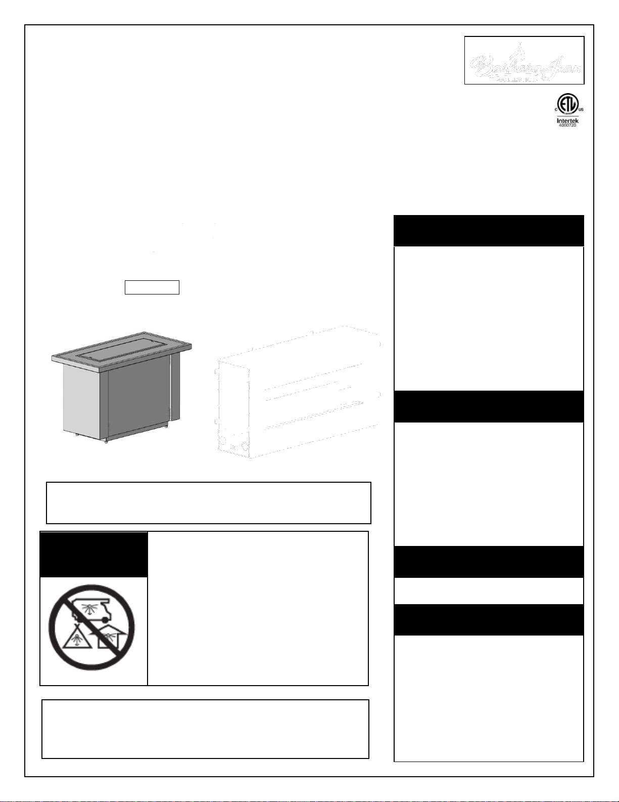
OUTDOOR LINEAR FIRE PIT MANUAL
⚠ DANGER
If you smell gas:
1. Shut off gas to the
appliance.
2. Extinguish any open flame.
3. If odor continues, keep
away from the appliance
and immediately call your
gas supplier or fire
department.
⚠ WARNING
Do not store or use gasoline
or other flammable vapors and
liquids in the vicinity of this or
any other appliance.
An LP-cylinder not connected
for use shall not be stored in
the vicinity of this or any other
appliance.
⚠ WARNING
For Outdoor Use Only.
⚠ WARNING
Improper installation,
adjustment, alteration, service
or maintenance can cause
injury or property damage.
Read the installation,
operating and maintenance
instructions thoroughly before
installing or servicing this
equipment.
⚠ DANGER
CARBON MONOXIDE HAZARD
This appliance can produce carbon
monoxide which has no odor.
Using it in an enclosed space can
kill you.
Never use this appliance in an
enclosed space such as a camper,
tent, car or home.
Kingsman Fireplaces 2340 Logan Ave., W innipeg, Mb Canada Ph: 204-632-1962 Printed in Canada P/N 24LFP-MAN April 4, 2017
INSTALLER: Leave this manual with the appliance.
CONSUMER: Retain this manual for future reference.
This appliance is designed as an “attended appliance”. Adults
must be present when the unit is operating. DO NOT leave this
unit burning when unattended. If this product is left burning
unattended it may cause damage or serious injury.
OLTN / OLTW
OUTDOOR FIRE TABLE
OFP S1 / S2
OUTDOOR FIREPLACE
OB
OUTDOOR BURNER
OFS
OUTDOOR FIRE STAND
VALVE
OUTDOOR BURNERS: OB24MAN, OB24MAP, OB24MVN, OB24MVP,
OB36MAN, OB36MAP, OB36MVN, OB36MVP,
OB48MAN, OB48MAP, OB48MVN, OB48MVP,
OB72MVN, OB72MVP, OB96MVN, OB96MVP
-CERTIFIED FOR USA & CANADA- ANSI Z21.97-2014 • CSA 2.41-2014 OUTDOOR DECORATIVE GAS APPLIANCES
NOTE: LP MANUAL (MAP) VALVE SYSTEMS ARE SHIPPED WITH AN ACCOMPANYING ORIFICE FOR NG CONVERSION.
ALL MILLIVOLT VALVE SYSTEMS ARE SHIPPED AS NG SYSTEMS (MVN) AND REQUIRE A CONVERSION KIT FOR LP CONVERSION.
OUTDOOR FIRE STANDS (c/w Burner): OFS24MAN, OFS24MAP, OFS36MAN, OFS36MAP, OFS48MAN, OFS48MAP
OUTDOOR FIRE TABLES (Burner Required): OLTN24, OLTW24, OLTN36, OLTW36, OLTN48, OLTW48
OUTDOOR FIREPLACES (Burner Required): OFP4336S1, OFP4336S2, OFP5548S1, OFP5548S2, OFP7972S1, OFP7972S2

Warnings, Installations and Operations
WARNING
FOR SAFE INSTALLATION AND OPERATION OF YOUR GAS FIREPLACE PLEASE NOTE THE FOLLOWING:
1. when an appliance is for connection to a fixed piping system, the installation must conform with local codes or,
in the absence of local codes, with the National Fuel Gas Code, ANSI Z223.1 • NFPA 54; National Fuel Gas
Code; Natural Gas and Propane Installation Code, CSA B149.1; or Propane Storage and Handling Code, CSA
B149.2, as applicable.
2. This appliance, when installed, must be electrically grounded in accordance with local codes or, in the absence
of local codes, with the National Electrical Code, ANSI/NFPA 70; or the Canadian Electrical Code, CSA C22.1,
if applicable.
3. THIS UNIT IS NOT FOR USE WITH SOLID FUEL.
4. Always keep the appliance clear and free from combustible materials, gasoline, and other flammable vapors
and liquids.
5. Inspect the fuel supply connection (including the hose for LP models) before each use of the appliance. See
Lighting Instructions for removal of Access Panel.
6. If it is evident there is excessive abrasion or wear, or the hose is damaged, it must be replaced prior to the
appliance being put into operation. Locate the hose out of pathways where people may trip over it or in areas
where the hose may be subject to accidental damage
7. Locate the hose out of pathways where people may trip over it or in areas where the hose may be subject to
accidental damage.
8. Children and adults should be alerted to the hazards of the high surface temperatures of this appliance and
should stay away to avoid burns or ignition of clothing.
9. Young children should be carefully supervised when they are in the area of the appliance.
10. Clothing or other flammable material should not be placed on or near the appliance. This appliance should not
be used as a drying rack for clothing.
11. Any safety screen or guard removed for servicing an appliance must be replaced prior to operating the
appliance.
12. Installation and repair should be done by a qualified service person. The appliance should be inspected before
use and at least annually by a professional service person. More frequent cleaning may be required due to
excessive lint from carpeting, et cetera. It is imperative that control compartments, burners and circulating air
passageways of the appliance be kept clean.
13. Do not use this appliance if any part has been under water. Immediately call a qualified service technician to
inspect the unit and to replace any part of the control system and any gas control which has been underwater.
2
This gas appliance must be installed by a qualified installer in accordance with local building codes, or in the absence of
local codes, with the current CAN/CSA-B149.1 or .2 Installation Code (in Canada) or the current National Fuel Gas Code
Z223.1- NFPA 54 when installed in the United States.
This appliance, when installed, must be electrically connected and grounded in accordance with local codes, or in the
absence of local codes, with the current CSA C22.1 Canadian Electrical Code or with the National Electrical Code;
ANSI/NFPA 70 when installed in the United States.
In the Commonwealth of Massachusetts, the installer or service
agent shall be a plumber or gas fitter licensed by the
Commonwealth of Massachusetts.
For the State of Massachusetts, flexible connectors shall not
exceed 36 inches in length.
For the state of Massachusetts a T-handle gas shut-off valve
must be used on a gas appliance.
Table of Contents
INTRODUCTION
Warnings, Installations and Operations……….........
2
Table of Contents………………………………..........
3
Pre-installation Questions and Answers……...........
4
Important Information About Outdoor
Fireplaces………………………………………...........
4
Locating Your Appliance / Outdoor Spaces…..........
5
Clearance Specifications……………………….........
6
Outdoor Burners Basic Models and
Applications………………………………………........
7
24 / 36 / 48 / 72 / 96 OUTDOOR BURNERS
Burner Systems for Custom Applications, OB /
OFS / OLTN / LTW / OFP Models……....................
8
Clearance to Combustibles for Outdoor Burners,
Outdoor Fire Stands, Outdoor Fire
Tables......................................................................
8
Dimensions - OB24 / OB36 / OB48 / OB72 / OB96
Outdoor Burners.......................................................
9
OB Burners – Unpacking and Setup – Manual
Valve Systems.........................................................
10
OB Burners – Unpacking and Setup – Millivolt
Valve Systems.........................................................
11
CUSTOM ENCLOSURES
Custom Enclosures-OB24 / 36 / 48 / 72 / 96............
12
Custom Enclosures – Optional LED Lighting...........
13
Enclosures for LP (Propane) Gas Supply
Systems...................................................................
14
OUTDOOR FIRE STANDS
Outdoor Fire Stands (OFS) Dimensions - OFS24 /
OFS36 / OFS48.......................................................
15
Outdoor Fire Stands (OFS) Unpacking and Setup...
16
OUTDOOR FIRE TABLES
Outdoor Fire Tables (OLTN / OLTW) Dimensions –
OLTN24 / OLTW24..................................................
17
Outdoor Fire Tables (OLTN / OLTW) Dimensions –
OLTN36 / OLTW36..................................................
18
Outdoor Fire Tables (OLTN / OLTW) Dimensions –
OLTN48 / OLTW48..................................................
19
Outdoor Fire Tables – Assembly..............................
20
Outdoor Fire Tables– Burner Installation.................
21
Outdoor Fire Tables – Optional LED Lighting..........
22
Outdoor Fire Tables – 20lb Cylinder Installation......
23
OUTDOOR FIREPLACES
Outdoor Fireplaces (OFP) OFP4336S1 &
OFP4336S2 Dimensions..........................................
24
Outdoor Fireplaces (OFP) OFP5548S1 &
OFP5548S2 Dimensions..........................................
25
Outdoor Fireplaces (OFP) OFP7972S1 &
OFP7972S2 Dimensions..........................................
26
Outdoor Fireplaces (OFP) – Handling Unit..............
27
Adjustable Support Guide -Hearth Flush With
Fireplace Opening....................................................
28
Outdoor Fireplace (OFP) Optional Framing (S1 &
S2)............................................................................
29
Outdoor Fireplace (OFP) Clearances and Mantels..
30
Surround Installation OFP43SS / OFP55SS /
OFP79SS.................................................................
31
Weather Cover Installation OFP43WC / OFP55WC
/ OFP79WC..............................................................
32
Outdoor Fireplace (OFP) Wind Guard Glass...........
33
About Stainless Steel Parts And Accessories..........
33
Outdoor Fireplace (OFP) Optional LED Lighting......
34
Outdoor Fireplace (OFP) Burner Removal &
Installation................................................................
35
ACCESSORIES AND OPTIONS
Glass Media for Outdoor Burners............................
36
Optional Media Accessories.....................................
36-37
Optional Wind Guards..............................................
38
MAINTENANCE
Burner System Maintenance....................................
39
General Maintenance Instructions...........................
40
BURNER LIGHTING / GAS INSTALLATION
Manual Lighting Instructions....................................
41
Millivolt Lighting Instructions....................................
42
Gas Line Installation.................................................
43
LP Cylinder Requirements / LP Conversion Kits......
44
Gas Conversion - Manual Systems..........................
45
Gas Conversion Part A – Millivolt Systems..............
46
Gas Conversion Part B – Top Convertible Pilot.......
47
Gas Conversion Part C – Valve Modulator..............
48
Optional Electronic Spark Assist..............................
49
Troubleshooting the Gas Control System................
50
PARTS LISTS
Plumbing Parts.........................................................
51
Outdoor Burners- Parts List......................................
52-53
Limited Warranty......................................................
54
3

Pre-installation Questions and Answers
Important Information About Outdoor Fireplaces
-Operating Instructions-
1. Be sure to read and understand all the
instructions in this manual before
operation of appliance.
2. Ensure all wiring is correct and properly
enclosed to prevent possible shock.
3. Check for gas leaks.
4. If brick or porcelain liners are used,
ensure they are installed.
5. Verify that the pilot can be seen when
lighting the appliance. If not, the log or
rock placement is incorrect.
6. If the unit is turned off, you must wait a
minimum of 60 seconds before relighting it.
4
About curing of the paint
Your stove or fireplace has been painted with the highest quality silicone
stove paint. This paint dries quickly in 15-20 minutes when first applied at
the factory. However, due to the high temperature silicone components,
the paint will cure when heat is applied to the appliance as it is first used.
The following information applies to the curing process to get the paint
fully hard and durable.
Fire the appliance four successive times for 10 minutes each firing and a
5 minute cool down between each. Be aware during log and firebox paint
curing that a white deposit may be developing on the inside of the glass
doors. It is important to remove this white deposit from the glass doors
using a fireplace glass cleaner.
Babies, small children, pregnant women and pets should leave
the area during the cure phase.
Ventilate well, open doors and windows.
Do not touch during curing.
Why does my fireplace or stove give off odour?
It is normal for your fireplace to give off some odor at first. This is due to the curing of the paint, adhesives, silicones and
any undetected oil from the manufacturing process as well as the finishing materials used with the installations (e.g.
marble, tile and the adhesives used to adhere this product to the walls can react with heat and cause odours).
It is recommended that you burn your gas fireplace or stove for a minimum of four hours at a time with the fan off (if a fan
is present) after the curing of the paint has been completed. These odours can last upward to 40 hours of burn time; keep
burning at a minimum of four hours per use until odours dissipate.
Noise coming from the fireplace?
Noise is caused by the expansion and contraction of metal as the appliance heats up and cools down. This is normal and
is similar to the sounds produced by a furnace or heating duct. This noise does not affect the operation or longevity of
your fireplace.
Note to the Installer:
Be sure appliance is working properly and its operation (including remote control operation, if included) is fully explained
to and understood by the customer.
Before you build in this appliance:
Do not insulate around the appliance. Heat buildup could lead to component failure.
Pay attention to all clearances to combustibles and specifications stated in this manual.
Drainage- If this appliance is installed in a location where it will be exposed to water and moisture, drainage is an
important consideration.
Inadequate drainage will cause rust, which is not covered by the warranty.
Information about outdoor fireplaces
Outdoor fire burning appliances may not function properly at all times regardless of the circumstances.
Wind can greatly affect flame performance. If used in windy conditions a wind guard is recommended.
Outdoor units require adequate ventilation in order to burn properly.
Restricted access to air is not only dangerous for persons near the appliance, but the appliance also will not
function correctly.
This appliance consumes air, burns fuel, and emits heat and exhaust gases.
Only approved media and accessories listed in this manual should be used with this appliance.
Locating Your Appliance
Note: Ventilation and air flow comes from openings in the walls and ceiling. Open floor space around the appliance
must not be considered ventilation and air flow space.
This unit requires combustion air and will produce exhaust gases. Install in an open-air situation with natural
ventilation and without stagnant areas.
Avoid installing in tight spaces and corners.
Be aware of combustibles (i.e. furniture) near appliance. Clearance is Minimum 36”.
By definition, an outdoor space is not enclosed. Any area in which these appliances are used shall comply with
the structures shown below.
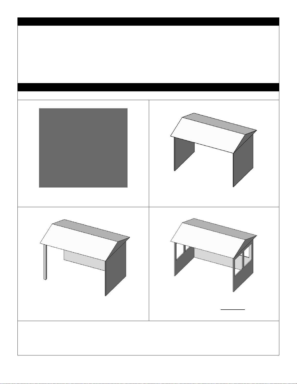
Locating Your Appliance – Outdoor Spaces
This appliance may be installed within the following structures:
1.
Walls on all sides (Minimum area of 96 square feet), but
with no overhead cover and at least one permanent
opening (doorway) at ground level.
2.
Within a partial enclosure that includes an overhead cover
and no more than two side walls.
3.
These side walls may be parallel, as in a breezeway, or at
right angles to each other.
4.
Within a partial enclosure that includes an overhead cover
and three side walls, as long as 30 percent or more of the
horizontal periphery of the enclosure is permanently open.
All models can be installed safely in a screened porch area within the following guidelines:
Minimum porch area is 96sq. feet with one side fully open.
A minimum of two (2) walls can be screened, but must be open to outside ventilation, with a minimum screen area of 64
sq. feet, and a minimum side wall height of 78” inches.
5
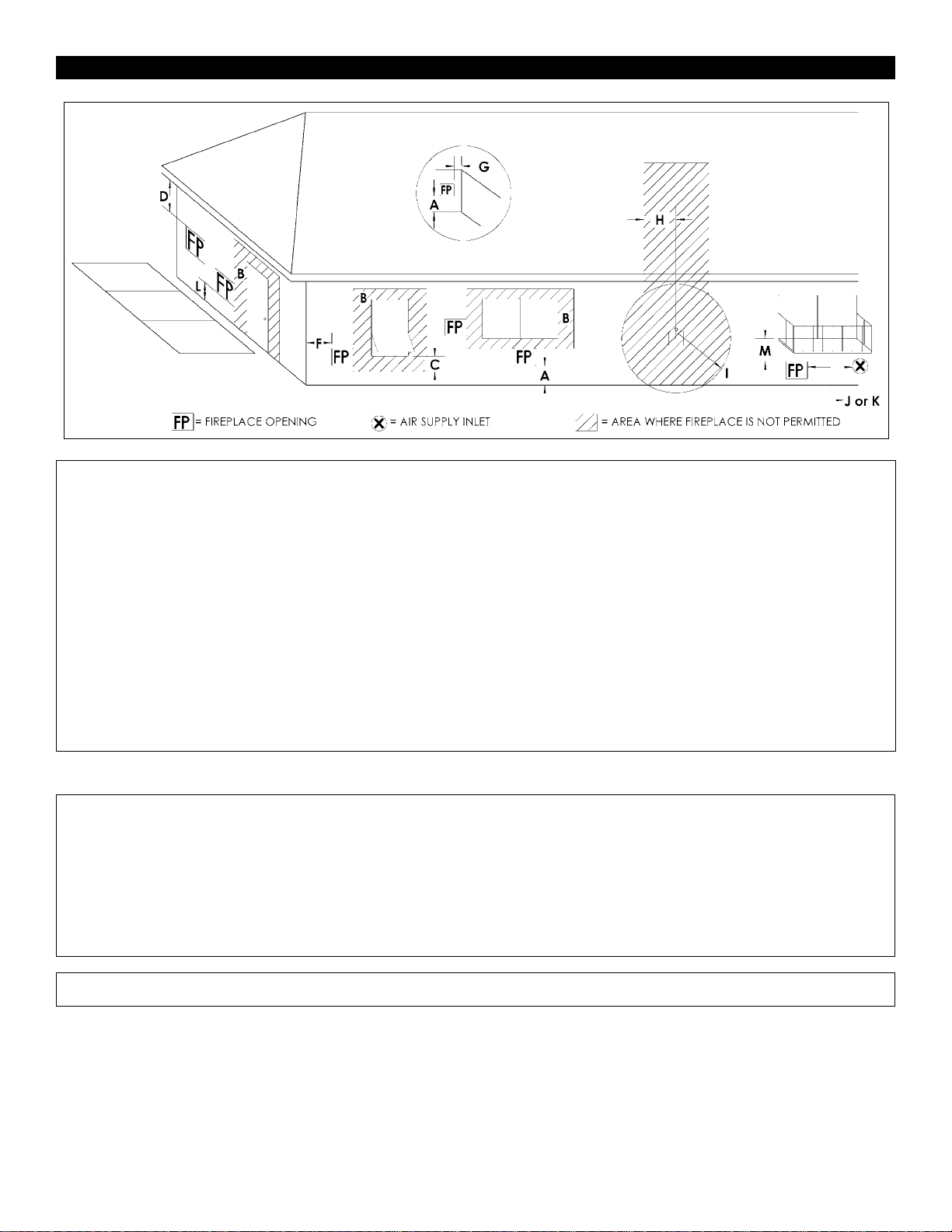
Clearance Specifications
A =
2in………….
Clearances above grade, veranda, porch,
deck or balcony.
I =
3ft (USA)……..
6ft (Canada)
Clearance to service regulator
vent outlet and electric service.
B =
12in…………
36in…………
Clearances to window or door that may be
opened, or to permanently closed window.
Vinyl windows or siding.
J =
9in (USA)…….
12in (Canada)
Clearance to non-mechanical air
Supply inlet to building or the
combustion air inlet to any other
appliance.
C =
12in…………
Clearance below an operable window.
K =
3ft (USA)…….
6ft (Canada)
Clearance to a mechanical air
supply inlet
D =
47in…………
60in…………
Vertical clearance to unventilated soffit or
to or to ventilated soffit located above the
fireplace.
Vinyl clad soffits.
L*=
54in………......
(See note 1)
Clearance above paved sidewalk
or a paved driveway located on
public property.
G =
3-1/2in…….
48in………..
Clearance to inside corner.
Vinyl windows or siding.
M**=
47in…………..
Clearance under veranda, porch,
deck, balcony or overhang.
H =
3ft. (Canada)
Not to be installed above a gas
meter/regulator assembly within 3ft
horizontally from the center line of the
regulator.
Not allowed….
Vinyl.
* A fireplace shall not open directly above a sidewalk or paved
driveway which is located between two single family
dwellings and services both swellings.
**Only permitted if veranda, porch, deck or balcony is fully
open on a minimum of 2 sides beneath the floor, or if the
screened porch guidelines are followed.
Note 1: Local codes or regulations may require different
clearances.
This appliance can be installed safely in a screened porch area
within the following guidelines:
Minimum porch area is 96sq. feet with one side fully open.
A minimum of two (2) walls can be screened, but must be open to
outside ventilation, with a minimum screen area of 64 sq. feet,
and a minimum side wall height of 78” inches.
Note: There may be some odor and small amounts of soot associated with burning the fireplace in a screened porch. Ensuring good
cross draft ventilation and routine maintenance of the fireplace will maximize comfort and cleanliness.
6
NOTE: Diagrams & Illustrations not to scale.
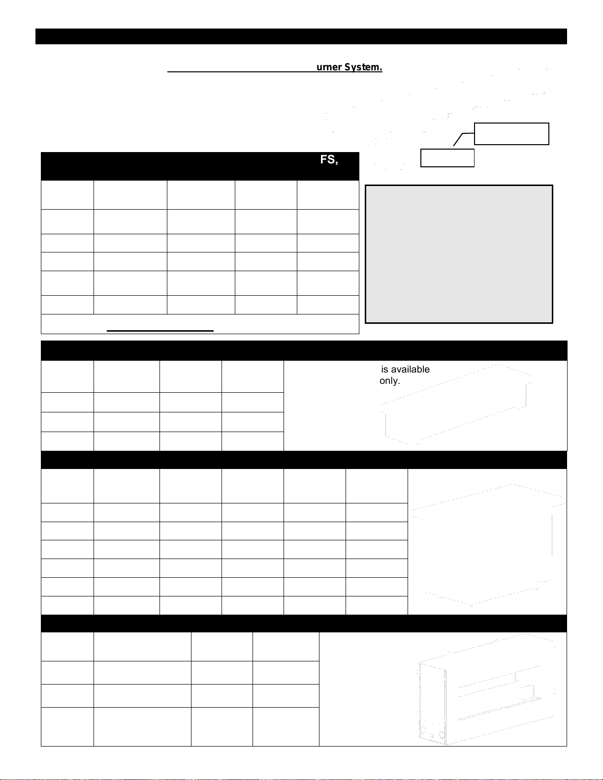
Outdoor Burners Basic Models and Applications
The Outdoor Burners (OB24, OB36, OB48, OB72, and OB96) are the basic component of the Barbara Jean
Series. These burners are a Complete Certified and Listed Burner System.
They consist of: -Burner
-Valve Control (Manual or Millivolt)
-Label
These burners can be placed into Custom Enclosures
which meet the specifications stated in the manual.
Burners for Custom Applications and Optional OFS,
OFT, and OFP Installations
LISTED
BURNER
MAP
Manual-LP
MAN
Manual-NG
MVP
Millivolt-LP
MVN
Millivolt-NG
OB24-
✔ c/w NG Orifice
✔
Conversion Kit
Required
✔
OB36-
✔ c/w NG Orifice
✔
Conversion Kit
Required
✔
OB48-
✔ c/w NG Orifice
✔
Conversion Kit
Required
✔
OB72-
N/A
N/A
Conversion Kit
Required
✔
OB96-
N/A
N/A
Conversion Kit
Required
✔
The following Approved Accessories can also be ordered:
Outdoor Fire Stand (OFS) Approved Accessory (Burner is Included)
LISTED
BURNER
OFS
Fire Stand
MAP
Manual-LP
MAN
Manual-NG
Outdoor Fire Stand is available
with a Manual Valve only.
OB24-
OFS24-
✔
✔
OB36-
OFS36-
✔
✔
OB48-
OFS48-
✔
✔
Outdoor Fire Tables (OLTN / OLTW) Approved Accessory (Burner is ordered separately)
LISTED
BURNER
OFT
Outdoor
Fire Table
MAP
Manual-LP
MAN
Manual-NG
MVP
Millivolt-LP
MVN
Millivolt-NG
Outdoor Fire Table
OB24-
OLTN24
✔
✔
Conversion Kit
Required
✔
OB24-
OLTW24
✔
✔
Conversion Kit
Required
✔
OB36-
OLTN36
✔
✔
Conversion Kit
Required
✔
OB36-
OLTW36
✔
✔
Conversion Kit
Required
✔
OB48-
OLTN48
✔
✔
Conversion Kit
Required
✔
OB48-
OLTW48
✔
✔
Conversion Kit
Required
✔
Outdoor Fireplace (OFP) Approved Accessory (Burner is included)
LISTED
BURNER
OFP
Outdoor Fireplace
MVP
Millivolt-LP
MVN
Millivolt-NG
Outdoor Fireplace
OB36-
OFP4336
S1 or S2
Conversion
Kit Required
✔
OB48-
OFP5548
S1 or S2
Conversion
Kit Required
✔
OB72-
OFP7972
S1 or S2
Conversion
Kit Required
✔
Label is attached
to Valve
VALVE
Burner systems may be connected
together in series (i.e. OB36MAP &
OB48MAP). See Custom Enclosures
section.
ALL LP MANUAL (MAP) VALVE SYSTEMS
ARE SHIPPED WITH AN ACCOMPANYING
ORIFICE FOR NG CONVERSION.
ALL MILLIVOLT VALVE SYSTEMS ARE
SHIPPED AS NG SYSTEMS (MVN) AND
REQUIRE A CONVERSION KIT FOR LP
CONVERSION.
7
-Burners-
Burner Systems for Custom Applications, OB / OFS / OLTN / OLTW / OFP Models
Burner
System c/w
Valve
Valve
System
Stocked Burner
Conversion Kit shown
Burner (OB) Dimensions
for Custom Applications
(Add 1/8” per side for
tolerance)
Outdoor
Fire Stand
(OFS)
Outdoor Fire
Table
(OLTN or OLTW )
Outdoor
Fireplace
(OFP)
OB24MAP
Dante
Manual
LP Burner
(c/w NG Orifice)
7-1/2” wide x 26” long
x 2” tall
OFS24MAP
OLTN24
OLTW24
N/A
OB24MAN
Dante
Manual
NG Burner
For LP order
24OB-CKLP5 or
24OB-CKLP10
7-1/2” wide x 26” long
x 2” tall
OFS24MAN
OLTN24
OLTW24
N/A
OB24MVN
SIT
Millivolt
NG Burner
For LP order 24OB-
CKLP
7-1/2” wide x 26” long
x 2” tall
N/A
OLTN24
OLTW24
N/A
OB36MAP
Dante
Manual
LP Burner
(c/w NG Orifice)
7-1/2” wide x 38” long
x 2” tall
OFS36MAP
OLTN36
OLTW36
N/A
OB36MAN
Dante
Manual
NG Burner
For LP order
36-48OB-CKLP5 or
36-48OB-CKLP10
7-1/2” wide x 38” long
x 2” tall
OFS36MAN
OLTN36
OLTW36
N/A
OB36MVN
SIT
Millivolt
NG Burner
For LP order
36OBCKLP
7-1/2” wide x 38” long
x 2” tall
N/A
OLTN36
OLTW36
OFP4336S1
OFP4336S2
OB48MAP
Dante
Manual
LP Burner
(c/w NG Orifice)
7-1/2” wide x 50” long
x 2” tall
OFS48MAP
OLTN48
OLTW48
N/A
OB48MAN
Dante
Manual
NG Burner
For LP order
36-48OB-CKLP5 or
36-48OB-CKLP10
7-1/2” wide x 50” long
x 2” tall
OFS48MAN
OLTN48
OLTW48
N/A
OB48MVN
SIT
Millivolt
NG Burner
For LP order
48OB-CKLP
7-1/2” wide x 50” long
x 2” tall
N/A
OLTN48
OLTW48
OFP5548S1
OFP5548S2
OB72MVN
SIT
Millivolt
NG Burner
For LP order
72OB-CKLP
7-1/2” wide x 74” long
x 2” tall
N/A
N/A
OFP7972S1
OFP7972S2
OB96MVN
SIT
Millivolt
NG Burner
For LP order
96OB-CKLP
7-1/2” wide x 98” long
x 2” tall
N/A
N/A
N/A
Burner systems may be connected together in series (i.e. OB36MAP & OB48MAP). See Custom Enclosures section.
LP MANUAL (MAP) VALVE SYSTEMS ARE SHIPPED WITH ACCOMPANYING ORIFICE FOR NG CONVERSION.
MILLIVOLT SYSTEMS ARE SHIPPED AS NG SYSTEMS (MVN) AND REQUIRE A CONVERSION KIT FOR LP CONVERSION.
Locating Your Appliance –Minimum Clearances to Combustibles
Outdoor Burners (OB24 / 36 / 48 / 72 / 96)
Outdoor Fire Stands (OFS24 / 36 / 48)
Outdoor Fire Tables (OLTN / OLTW24 / 36 / 48)
Clearance
Dimension
Measured From:
A: Side wall
24”
Side of Burner Tray
B: End wall
12”
End of Burner Tray
C: Ceiling
49-1/2”
Top of Burner Tray
D: Floor
8”
Top of Burner Tray
A
C
D
WARNING
-RISK OF FIRE-
All minimum clearances
must be adhered to.
CEILING
8
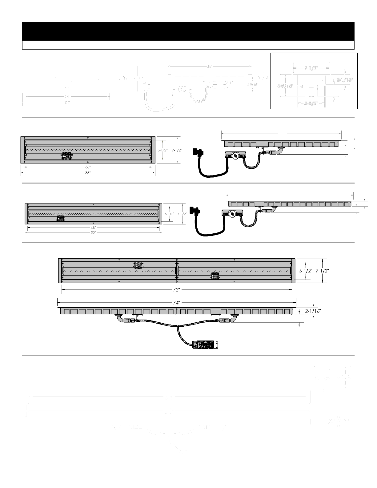
Certified Burners with Label
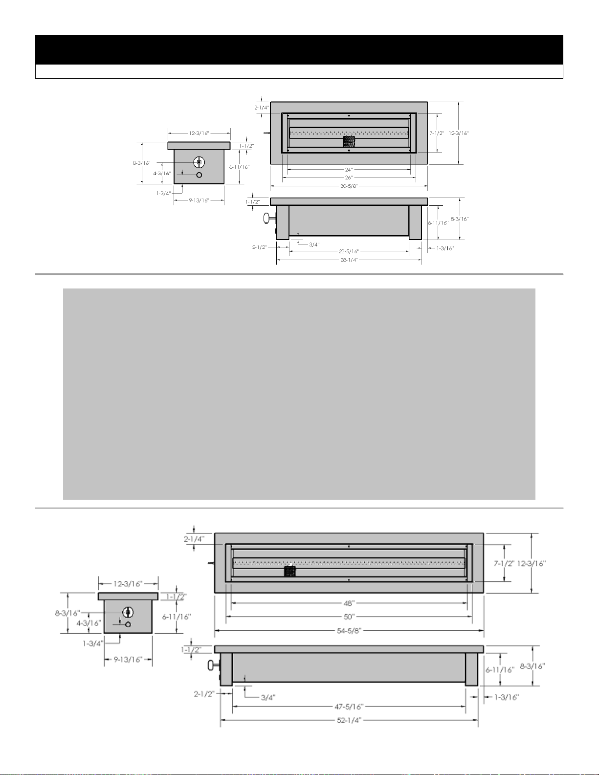
Dimensions OB24 / OB36 / OB48 / OB72 / OB96 (Outdoor Burners)
END VIEW- ALL BURNERS
2-1/16”
2-5/16”
38”
2-5/16”
2-1/16”
50”
2-5/16”
2-5/16”
2-5/16”
9
OB24 BURNER
OB36 BURNER
OB48 BURNER
OB72 BURNER
OB96 BURNER
OB Burners – Unpacking and Setup – Manual Valve Systems
.
STEP 1: Insert Burner Orifice into mixing sleeve and attach Orifice
Retainer Bracket with [2] 1/2” DT Screws. Then insert Electrode Mount
Plate and Sparker into Burner and install with [2] 1/2” DT Screws.
STEP 2: Install Burner with attached Valve
System into structure.
For Outdoor Fire Tables (OFT) refer to
OFT Burner Installation Instructions.
For Outdoor Fireplaces (OFP) refer to OFP
Burner Installation Instructions.
Refer to Custom Enclosures Section for
Custom Enclosures.
NOTE: Filler Strips must be installed
before media is placed into burner.
Parts List: OB24 / OB36 / OB48 MAP/MAN
[1] Burner, c/w [1] Pilot Shield, [2] Ends, [3] Filler Strips
[1] Manual Valve System (c/w Regulator and 5ft Hose for LP
Systems)
[1] Push Button Igniter c/w wire and Sparker
[1] Valve Key
[1] Key Way Installation Tool
[1] Brass Orifice for NG Conversion (LP Systems)
[1] Tank Retainer (LP Systems)
[1] Hardware Bag: [8] 1/2” DT Screws, [4] #6 Black Screws, [2]
#10 Woodscrews
[3] Filler Strips (See Below)
Orifice Retainer
Bracket
Electrode Mount Plate
and Sparker
24OB – 23-9/16”
36OB – 35-9/16”
48OB – 47-9/16”
24OB – 10-5/8”
36OB – 10-5/8”
48OB – 10-5/8”
24OB – 10-5/8”
36OB – 22-5/8”
48OB – 34-5/8”
FILLER STRIPS:
Long Flange Up
Short Flange Down
Qty [4] 1/2” DT Screws
to attach Valve
NG Conversion Orifices
(Included with MAP Burners)
OB24MAP - #40
OB36MAP - #31
OB48MAP - #30
Air Shutter = 1/16”- NG
Air Shutter = Full Open- LP
10
OB Burners – Unpacking and Setup – Millivolt Valve Systems
STEP 1 (For OB72 & OB96 only):
Connect Burners using [2] 10-24 x
1/2” bolts. Set Cover Clip over joined
burner ends.
STEP 2: Insert Orifice(s)
into mixing sleeve(s) and
install bracket(s) with [4]
1/2” DT Screws. Then
insert Pilot Assembly into
one Burner and attach with
[2] 1/2” DT Screws.
Attach Pilot Opening Cover
in the other Burner with [2]
1/2”DT Screws.
Air Shutter = 1/16”- NG
Air Shutter = Full Open- LP
STEP 3: Install Burner with attached Valve System into structure.
For Outdoor Fire Tables (OFT) refer to OFT Burner Installation Instructions page.
For Outdoor Fireplaces (OFP) refer to OFP Burner Installation Instructions page.
For Custom Enclosures refer to Custom Enclosures Section.
NOTE: Filler Strips must be installed before media is placed into burner.
Parts List: OB72 / OB96MVN
[2] Burners, c/w [2] Pilot Shields, [2] Ends, [6] Filler Strips
[1] Millivolt Valve System (c/w [2] Orifice Assemblies and [1] Pilot
Assembly)
[1] Piezo Button Igniter c/w wire and Sparker
[1] On/Off Rocker Switch (installed on valve)
[1] Pilot Opening Cover
[1] Hardware Bag: [12] 1/2” DT Screws, [8] #6 Black Screws, [2]
10-24 x 1/2” Bolts c/w Star Nuts
[6] Filler Strips
[1] Cover Clip
24OB – 23-9/16”
36OB – 35-9/16” (x 2 for OB72)
48OB – 47-9/16” (x 2 for OB96)
24OB – 10-5/8”
36OB – 10-5/8” (x 2 for OB72)
48OB – 10-5/8” (x 2 for OB96)
24OB – 10-5/8”
36OB – 22-5/8” (x 2 for OB72)
48OB – 34-5/8” (x 2 for OB96)
Connect Electrode
Wire to Piezo.
Connect On/Off
Switch to TP and
TH Terminals.
Connect Electrode Wire to
Piezo.
Connect On/Off Switch to
TP and TH Terminals.
Install Pilot Assembly and
Orifice Bracket [4 Dt Screws].
Cover Clip
Pilot Assembly is
installed from
bottom of Burner
Tray – but can be
serviced from the
Top.
Parts List: OB24 / OB36 / OB48MVN
[1] Burner, c/w [1] Pilot Shield, [2] Ends, [3] Filler Strips
[1] Millivolt Valve System (c/w Orifice Assembly and Pilot Assembly)
[1] Piezo Button Igniter c/w wire and Sparker
[1] On/Off Rocker Switch (Installed on valve)
[1] Hardware Bag: [8] 1/2” DT Screws, [4] #6 Black Screws
[3] Filler Strips (See Below)
Orifice
Retainer
Bracket
Pilot Opening
Cover
FILLER STRIPS:
[Qty 4] 1/2”
DT Screws
to attach
valve to
appliance
Long Flange Up
Short Flange
Down
[Qty 2] 1/2”
DT Screws
[Qty 2] 1/2”
DT Screws
11
-Custom Enclosures-
OB24 / 36 / 48 / 72 / 96 (Must be non-combustible)
Multiple burners can be connected together in series. ENCLOSURES MUST BE NON-COMBUSTIBLE. Enclosures
3” MIN
3” MIN
5-3/4”
Required Openings for
Stock Burners
OB24 – 5-3/4” x 24-1/2”
OB36 – 5-3/4” x 36-1/2”
OB48 – 5-3/4” x 48-1/2”
OB72 – 5-3/4” x 72-1/2”
OB96 – 5-3/4” x 96-1/2”
Burners may be connected
together in any combination.
When connecting additional
burners, add desired lengths
(24”, 36”, 48”, 72”, 96”) plus
Required Opening for total
opening (e.g. 24” + 72-1/2” +
24” = 120-1/2”).
NOTE: Flame height will be
noticeably higher on OB48
burners. This can be manually
adjusted.
Remove ends when
connecting burners.
END VIEW
ALL BURNERS
Maximum height of
media is 1” above tray.
LED Light Strips must be
at least 1-5/8” below and
2-5/8” away from Burner
Tray.
LED
Light
Strip
LED
Light
Strip
8” MIN
8” MIN
8” MIN
Burner Tray must
be supported.
REFER TO Enclosures for LP
(Propane) Gas Supply
Systems
NOTE: All Gas Controls and
connections must be readily
removable, supported, or accessible.
12
shown are suggestions only. Refer to Clearance to Combustibles section of manual.
NOTE: all manual valve systems are shipped as LP systems (MAP) with accompanying orifice for NG conversion.
All millivolt valve systems are shipped as NG systems (MVN) and require a conversion kit for LP conversion.
NOTE: For propane installations see Enclosures for LP (Propane) Gas Supply Systems.
Optional LED Lighting – Custom Enclosures
Please follow the current ANSI/NFPA 70 National Electrical Code in the USA and CAN/CSA C22.1 Canadian
National Electrical Code in Canada.
⚠ WARNING
Electrical Grounding Instructions
This appliance is equipped with a three prong (grounding)
plug for your protection against shock hazard and should be
plugged directly into a properly grounded three-prong
receptacle. Do not cut or remove the grounding prong from
this.
The fireplace receptacle must be connected to an
external GFI protected outlet installed near the fireplace.
Before Servicing
1. Ensure all power supply is shut off.
2. Label all wires prior to disconnecting when servicing
control. Wiring errors can cause improper and
dangerous operation.
SIDE VIEW
CUSTOM
ENCLOSURE
-Junction Box-
Must be connected to
an external GFI outlet
JUNCTION
BOX
LED
CONTROL
BOX
LED LIGHT
STRIP
LED LIGHT
STRIP
13
NOTE: If appliance is directly connected to an electrical supply, it must be anchored using anchor points provided in
bottom of appliance. Use cord and wire restraints provided also.
Enclosures for LP (Propane) Gas Supply Systems
LP cylinder with retention
device attached.
Combustible
Combustible
14
If you build an enclosure for an LP gas cylinder you must
follow these specifications. You must also follow local
codes.
An enclosure for an LP-gas cylinder shall be ventilated by
openings at both the upper and lower levels of the
enclosure. This shall be accompanied by one of the
following:
a. One side of the enclosure shall be completely open; or
b. For an enclosure having four sides, a top, and a bottom:
1. At least two ventilation openings shall be provided in the
sidewalls of the enclosure, located within 5 in (217 mm) of
the top of the enclosure, equally sized, spaced at a
minimum of 90 degrees (1.57 rad), and unobstructed. The
opening(s) shall have a total free area of not less than
1square inch per pound (14.2 cm2Ckg) of stored fuel
capacity.
2. Ventilation opening(s) shall be provided at floor level of
the enclosure and shall have a total free area of not less
than 1/2 square inches per pound (7.1 cm2Ckg) of stored
fuel capacity. If ventilation openings at floor level are in a
sidewall, there shall be at least two openings. The bottom
of the openings shall be 1 in (25.4 mm) or less from the
floor level and the upper edge no more than 5 in (127
mm) above the floor level. The openings shall be equally
sized, spaced at a minimum of 90 degrees (1.57 rad),
and unobstructed.
3. Every opening shall have minimum dimensions so as to
permit the entrance of a 1/8 in (3.2 mm) diameter rod.
4. Ventilation openings in sidewalls shall not communicate
directly with other enclosures of the appliance.
The cylinder valve shall be readily accessible for hand
operation. A door on the enclosure to gain access to the
cylinder valves is acceptable, provided it is non-locking and
can be opened without the use of tools. Designs using a
cover to gain access to the cylinder and cylinder valve shall
be provided with handles or equivalent at a minimum of 180
degrees apart to facilitate lifting of the cover.
The enclosure for the LP-gas cylinder shall isolate the
cylinder from the burner compartment to provide:
a. Shielding from radiation;
b. A flame barrier; and
c. Protection from foreign material.
There shall be a minimum clearance of 2 in (50.8 mm)
between the floor of the non-disposable LP-gas cylinder
enclosure and the ground.
The design of the fireplace shall be such that:
a. A non-disposable LP-gas cylinder can be connected,
disconnected, and the connections inspected and tested
outside the cylinder enclosure; and
b. Those connections which could be disturbed when
installing the cylinder in the enclosure can be leak tested
inside the enclosure.
Be certain to mount or set the LP-gas cylinder on a flat
stable surface and retain it to prevent it from tipping.
Purge the gas supply line of any trapped air prior to the
first firing of the unit.
WARNING: During the initial purging and subsequent
lightings, NEVER allow gas valve to remain in "OPEN"
position without first placing a burning match on the top
of the burner.
Test fire the unit after referring to the SAFETY
INFORMATION and LIGHTING INSTRUCTIONS.
If
LP-Gas outdoor fire
pits
are used
continuously after a
couple
of
hours,
you
could
see the
possibility of the
decreasing
this
happens,
the
control valve
the tank
wait a
valve
couple
flame
in size. If
turn off
and
and
of
hours
before lighting again
or switch
tanks. The
tank is
to the
being taken
propane
propane
freezing
volume
up due
of gas
out of the
tank.
Fire Stands – Approved Accessory
OFS Series Dimensions (Outdoor Fire Stand)
OFS24MAP / OFS24MAN
15
OFS36MAP / OFS36MAN
OFS48MAP / OFS48MAN
OFS Outdoor Fire Stands – Unpacking and Setup
Parts List: OFS24 / OFS36 / OFS48 – MAP/MAN
[1] OFS Outdoor Fire Stand c/w Burner, Valve System and 10ft LP
Hose & Regulator (Installed)
[3ea] Filler Strips
[1] Push Button Igniter (AAA Battery not included) c/w Wire and
Sparker (Installed)
[1] Valve Key
[1] Key Way Installation Tool
[1] Brass Orifice for NG Gas Conversion (LP Systems)
[1] Tank Retainer, [2ea] Wood Screws (LP Systems)
OFS24 Shown – Ready for Media Placement.
See Media Section of Manual for Options.
END VIEW – Outdoor Fire Stand
FILLER STRIPS:
24OB – 23-9/16”
36OB – 35-9/16”
48OB – 47-9/16”
ALL UNITS – 10-5/8”
24OB – 10-5/8”
36OB – 22-5/8”
48OB – 34-5/8”
OFP Bottom View
(MAP System Shown)
INCLUDED WITH MAP (PROPANE)
BURNER SYSTEMS ONLY
Long Flange at Top
Short Flange at Bottom
BURNER END VIEW
Valve Control
Push Button Igniter – Unscrew and insert AAA
Battery here.
16
Fire Tables –Approved Accessory
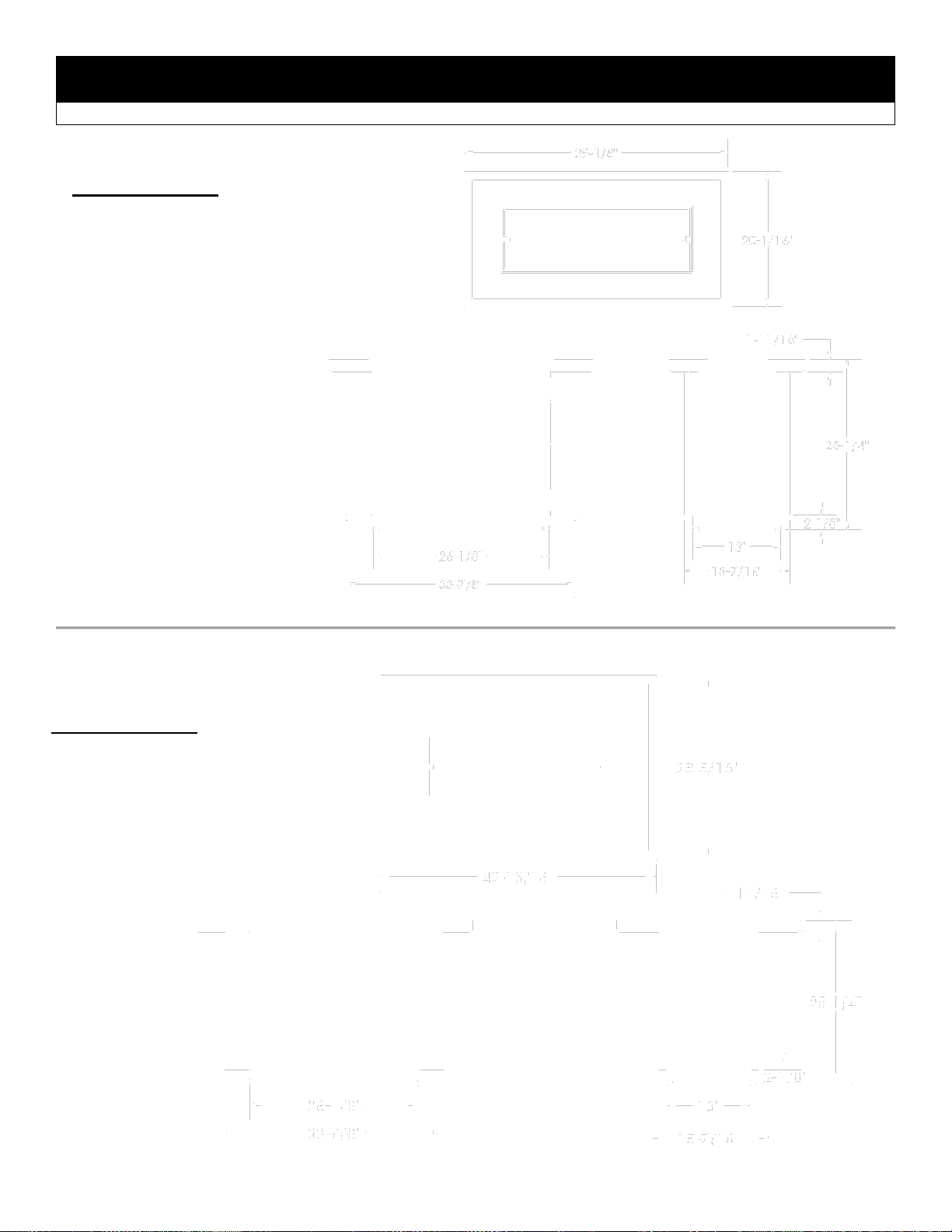
OLTN24 and OLTW24 Dimensions (Outdoor Fire Table)
OLTN24
BURNER OPTIONS:
OB24MAP (c/w #40 Orifice for NG)
OB24MAN (Order 24OB-CKLP5 for LP)
OB24MVN (Order 24OB-CKLP for LP)
OLTW24
BURNER OPTIONS:
OB24MAP (c/w #40 Orifice for NG)
OB24MAN (Order 24OB-CKLP5 for LP)
OB24MVN (Order 24OB-CKLP for LP)
17
 Loading...