

Page 1
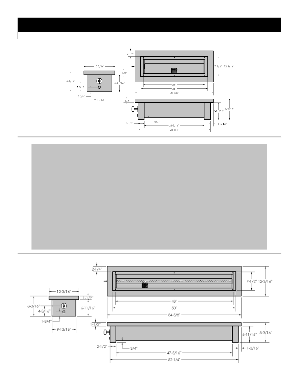
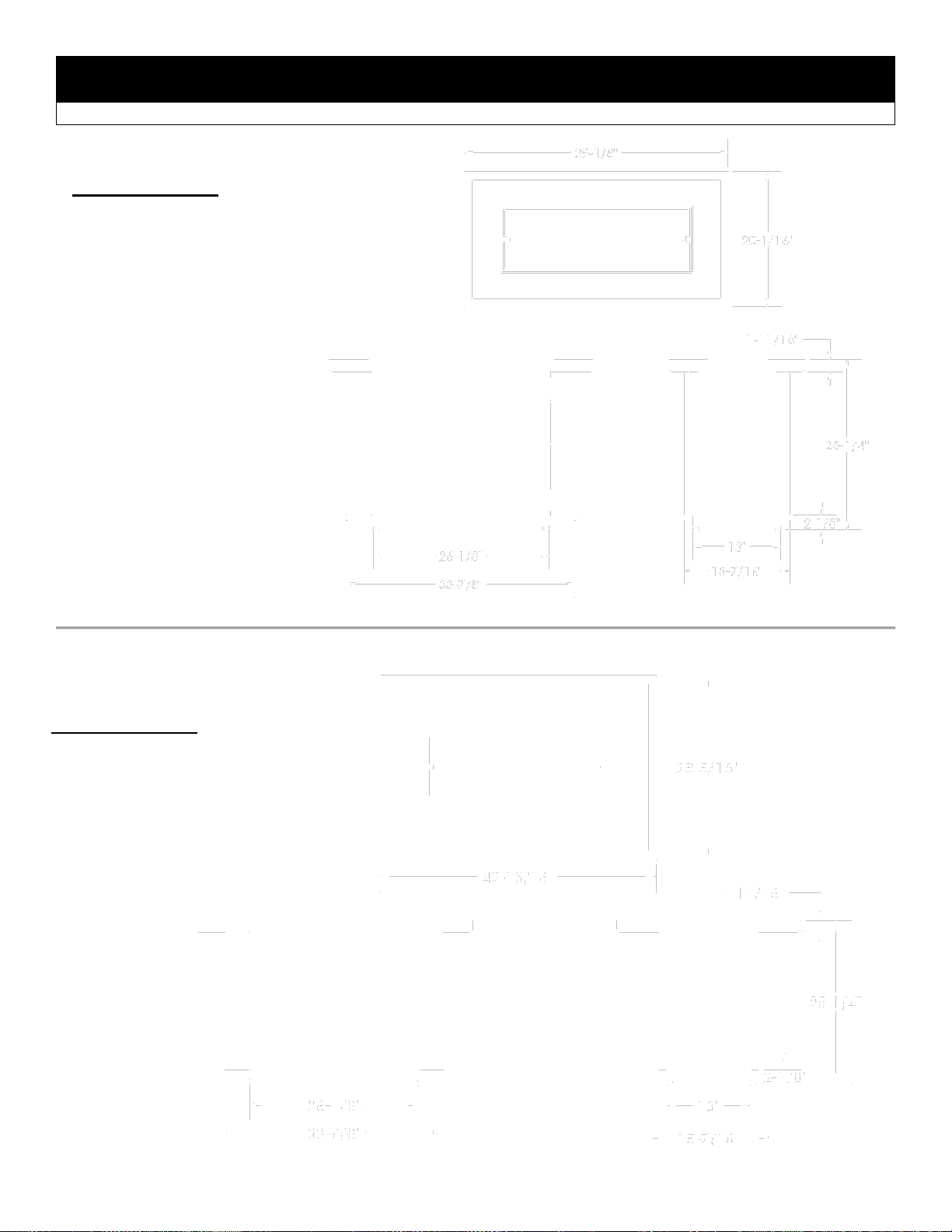
OUTDOOR LINEAR FIRE PIT MANUAL
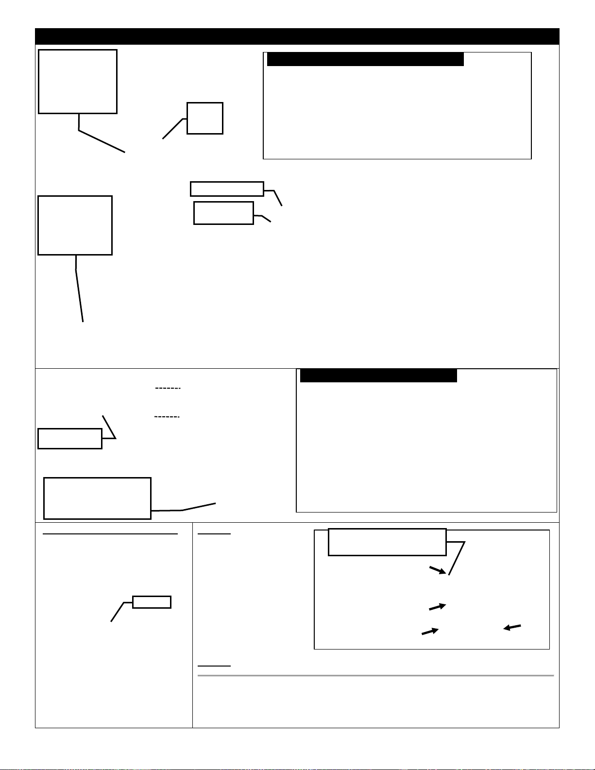
⚠ DANGER
If you smell gas:
1. Shut off gas to the
appliance.
2. Extinguish any open flame.
3. If odor continues, keep
away from the appliance
and immediately call your
gas supplier or fire
department.
⚠ WARNING
Do not store or use gasoline
or other flammable vapors and
liquids in the vicinity of this or
any other appliance.
An LP-cylinder not connected
for use shall not be stored in
the vicinity of this or any other
appliance.
⚠ WARNING
For Outdoor Use Only.
⚠ WARNING
Improper installation,
adjustment, alteration, service
or maintenance can cause
injury or property damage.
Read the installation,
operating and maintenance
instructions thoroughly before
installing or servicing this
equipment.
⚠ DANGER
CARBON MONOXIDE HAZARD
This appliance can produce carbon
monoxide which has no odor.
Using it in an enclosed space can
kill you.
Never use this appliance in an
enclosed space such as a camper,
tent, car or home.
Kingsman Fireplaces 2340 Logan Ave., W innipeg, Mb Canada Ph: 204-632-1962 Printed in Canada P/N 24LFP-MAN April 4, 2017
INSTALLER: Leave this manual with the appliance.
CONSUMER: Retain this manual for future reference.
This appliance is designed as an “attended appliance”. Adults
must be present when the unit is operating. DO NOT leave this
unit burning when unattended. If this product is left burning
unattended it may cause damage or serious injury.
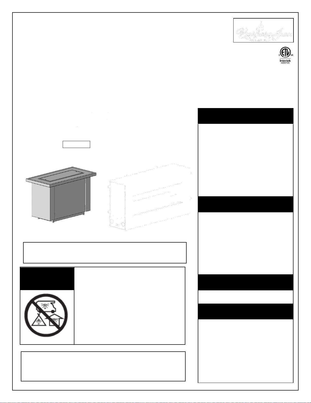
OLTN / OLTW
OUTDOOR FIRE TABLE
OFP S1 / S2
OUTDOOR FIREPLACE
OB
OUTDOOR BURNER
OFS
OUTDOOR FIRE STAND
VALVE
OUTDOOR BURNERS: OB24MAN, OB24MAP, OB24MVN, OB24MVP,
OB36MAN, OB36MAP, OB36MVN, OB36MVP,
OB48MAN, OB48MAP, OB48MVN, OB48MVP,
OB72MVN, OB72MVP, OB96MVN, OB96MVP
-CERTIFIED FOR USA & CANADA- ANSI Z21.97-2014 • CSA 2.41-2014 OUTDOOR DECORATIVE GAS APPLIANCES
NOTE: LP MANUAL (MAP) VALVE SYSTEMS ARE SHIPPED WITH AN ACCOMPANYING ORIFICE FOR NG CONVERSION.
ALL MILLIVOLT VALVE SYSTEMS ARE SHIPPED AS NG SYSTEMS (MVN) AND REQUIRE A CONVERSION KIT FOR LP CONVERSION.
OUTDOOR FIRE STANDS (c/w Burner): OFS24MAN, OFS24MAP, OFS36MAN, OFS36MAP, OFS48MAN, OFS48MAP
OUTDOOR FIRE TABLES (Burner Required): OLTN24, OLTW24, OLTN36, OLTW36, OLTN48, OLTW48
OUTDOOR FIREPLACES (Burner Required): OFP4336S1, OFP4336S2, OFP5548S1, OFP5548S2, OFP7972S1, OFP7972S2
Page 2

Warnings, Installations and Operations
WARNING
FOR SAFE INSTALLATION AND OPERATION OF YOUR GAS FIREPLACE PLEASE NOTE THE FOLLOWING:
1. when an appliance is for connection to a fixed piping system, the installation must conform with local codes or,
in the absence of local codes, with the National Fuel Gas Code, ANSI Z223.1 • NFPA 54; National Fuel Gas
Code; Natural Gas and Propane Installation Code, CSA B149.1; or Propane Storage and Handling Code, CSA
B149.2, as applicable.
2. This appliance, when installed, must be electrically grounded in accordance with local codes or, in the absence
of local codes, with the National Electrical Code, ANSI/NFPA 70; or the Canadian Electrical Code, CSA C22.1,
if applicable.
3. THIS UNIT IS NOT FOR USE WITH SOLID FUEL.
4. Always keep the appliance clear and free from combustible materials, gasoline, and other flammable vapors
and liquids.
5. Inspect the fuel supply connection (including the hose for LP models) before each use of the appliance. See
Lighting Instructions for removal of Access Panel.
6. If it is evident there is excessive abrasion or wear, or the hose is damaged, it must be replaced prior to the
appliance being put into operation. Locate the hose out of pathways where people may trip over it or in areas
where the hose may be subject to accidental damage
7. Locate the hose out of pathways where people may trip over it or in areas where the hose may be subject to
accidental damage.
8. Children and adults should be alerted to the hazards of the high surface temperatures of this appliance and
should stay away to avoid burns or ignition of clothing.
9. Young children should be carefully supervised when they are in the area of the appliance.
10. Clothing or other flammable material should not be placed on or near the appliance. This appliance should not
be used as a drying rack for clothing.
11. Any safety screen or guard removed for servicing an appliance must be replaced prior to operating the
appliance.
12. Installation and repair should be done by a qualified service person. The appliance should be inspected before
use and at least annually by a professional service person. More frequent cleaning may be required due to
excessive lint from carpeting, et cetera. It is imperative that control compartments, burners and circulating air
passageways of the appliance be kept clean.
13. Do not use this appliance if any part has been under water. Immediately call a qualified service technician to
inspect the unit and to replace any part of the control system and any gas control which has been underwater.
2
This gas appliance must be installed by a qualified installer in accordance with local building codes, or in the absence of
local codes, with the current CAN/CSA-B149.1 or .2 Installation Code (in Canada) or the current National Fuel Gas Code
Z223.1- NFPA 54 when installed in the United States.
This appliance, when installed, must be electrically connected and grounded in accordance with local codes, or in the
absence of local codes, with the current CSA C22.1 Canadian Electrical Code or with the National Electrical Code;
ANSI/NFPA 70 when installed in the United States.
In the Commonwealth of Massachusetts, the installer or service
agent shall be a plumber or gas fitter licensed by the
Commonwealth of Massachusetts.
For the State of Massachusetts, flexible connectors shall not
exceed 36 inches in length.
For the state of Massachusetts a T-handle gas shut-off valve
must be used on a gas appliance.
Page 3
Table of Contents
INTRODUCTION
Warnings, Installations and Operations……….........
2
Table of Contents………………………………..........
3
Pre-installation Questions and Answers……...........
4
Important Information About Outdoor
Fireplaces………………………………………...........
4
Locating Your Appliance / Outdoor Spaces…..........
5
Clearance Specifications……………………….........
6
Outdoor Burners Basic Models and
Applications………………………………………........
7
24 / 36 / 48 / 72 / 96 OUTDOOR BURNERS
Burner Systems for Custom Applications, OB /
OFS / OLTN / LTW / OFP Models……....................
8
Clearance to Combustibles for Outdoor Burners,
Outdoor Fire Stands, Outdoor Fire
Tables......................................................................
8
Dimensions - OB24 / OB36 / OB48 / OB72 / OB96
Outdoor Burners.......................................................
9
OB Burners – Unpacking and Setup – Manual
Valve Systems.........................................................
10
OB Burners – Unpacking and Setup – Millivolt
Valve Systems.........................................................
11
CUSTOM ENCLOSURES
Custom Enclosures-OB24 / 36 / 48 / 72 / 96............
12
Custom Enclosures – Optional LED Lighting...........
13
Enclosures for LP (Propane) Gas Supply
Systems...................................................................
14
OUTDOOR FIRE STANDS
Outdoor Fire Stands (OFS) Dimensions - OFS24 /
OFS36 / OFS48.......................................................
15
Outdoor Fire Stands (OFS) Unpacking and Setup...
16
OUTDOOR FIRE TABLES
Outdoor Fire Tables (OLTN / OLTW) Dimensions –
OLTN24 / OLTW24..................................................
17
Outdoor Fire Tables (OLTN / OLTW) Dimensions –
OLTN36 / OLTW36..................................................
18
Outdoor Fire Tables (OLTN / OLTW) Dimensions –
OLTN48 / OLTW48..................................................
19
Outdoor Fire Tables – Assembly..............................
20
Outdoor Fire Tables– Burner Installation.................
21
Outdoor Fire Tables – Optional LED Lighting..........
22
Outdoor Fire Tables – 20lb Cylinder Installation......
23
OUTDOOR FIREPLACES
Outdoor Fireplaces (OFP) OFP4336S1 &
OFP4336S2 Dimensions..........................................
24
Outdoor Fireplaces (OFP) OFP5548S1 &
OFP5548S2 Dimensions..........................................
25
Outdoor Fireplaces (OFP) OFP7972S1 &
OFP7972S2 Dimensions..........................................
26
Outdoor Fireplaces (OFP) – Handling Unit..............
27
Adjustable Support Guide -Hearth Flush With
Fireplace Opening....................................................
28
Outdoor Fireplace (OFP) Optional Framing (S1 &
S2)............................................................................
29
Outdoor Fireplace (OFP) Clearances and Mantels..
30
Surround Installation OFP43SS / OFP55SS /
OFP79SS.................................................................
31
Weather Cover Installation OFP43WC / OFP55WC
/ OFP79WC..............................................................
32
Outdoor Fireplace (OFP) Wind Guard Glass...........
33
About Stainless Steel Parts And Accessories..........
33
Outdoor Fireplace (OFP) Optional LED Lighting......
34
Outdoor Fireplace (OFP) Burner Removal &
Installation................................................................
35
ACCESSORIES AND OPTIONS
Glass Media for Outdoor Burners............................
36
Optional Media Accessories.....................................
36-37
Optional Wind Guards..............................................
38
MAINTENANCE
Burner System Maintenance....................................
39
General Maintenance Instructions...........................
40
BURNER LIGHTING / GAS INSTALLATION
Manual Lighting Instructions....................................
41
Millivolt Lighting Instructions....................................
42
Gas Line Installation.................................................
43
LP Cylinder Requirements / LP Conversion Kits......
44
Gas Conversion - Manual Systems..........................
45
Gas Conversion Part A – Millivolt Systems..............
46
Gas Conversion Part B – Top Convertible Pilot.......
47
Gas Conversion Part C – Valve Modulator..............
48
Optional Electronic Spark Assist..............................
49
Troubleshooting the Gas Control System................
50
PARTS LISTS
Plumbing Parts.........................................................
51
Outdoor Burners- Parts List......................................
52-53
Limited Warranty......................................................
54
3
Page 4

Pre-installation Questions and Answers
Important Information About Outdoor Fireplaces
-Operating Instructions-
1. Be sure to read and understand all the
instructions in this manual before
operation of appliance.
2. Ensure all wiring is correct and properly
enclosed to prevent possible shock.
3. Check for gas leaks.
4. If brick or porcelain liners are used,
ensure they are installed.
5. Verify that the pilot can be seen when
lighting the appliance. If not, the log or
rock placement is incorrect.
6. If the unit is turned off, you must wait a
minimum of 60 seconds before relighting it.
4
About curing of the paint
Your stove or fireplace has been painted with the highest quality silicone
stove paint. This paint dries quickly in 15-20 minutes when first applied at
the factory. However, due to the high temperature silicone components,
the paint will cure when heat is applied to the appliance as it is first used.
The following information applies to the curing process to get the paint
fully hard and durable.
Fire the appliance four successive times for 10 minutes each firing and a
5 minute cool down between each. Be aware during log and firebox paint
curing that a white deposit may be developing on the inside of the glass
doors. It is important to remove this white deposit from the glass doors
using a fireplace glass cleaner.
Babies, small children, pregnant women and pets should leave
the area during the cure phase.
Ventilate well, open doors and windows.
Do not touch during curing.
Why does my fireplace or stove give off odour?
It is normal for your fireplace to give off some odor at first. This is due to the curing of the paint, adhesives, silicones and
any undetected oil from the manufacturing process as well as the finishing materials used with the installations (e.g.
marble, tile and the adhesives used to adhere this product to the walls can react with heat and cause odours).
It is recommended that you burn your gas fireplace or stove for a minimum of four hours at a time with the fan off (if a fan
is present) after the curing of the paint has been completed. These odours can last upward to 40 hours of burn time; keep
burning at a minimum of four hours per use until odours dissipate.
Noise coming from the fireplace?
Noise is caused by the expansion and contraction of metal as the appliance heats up and cools down. This is normal and
is similar to the sounds produced by a furnace or heating duct. This noise does not affect the operation or longevity of
your fireplace.
Note to the Installer:
Be sure appliance is working properly and its operation (including remote control operation, if included) is fully explained
to and understood by the customer.
Before you build in this appliance:
Do not insulate around the appliance. Heat buildup could lead to component failure.
Pay attention to all clearances to combustibles and specifications stated in this manual.
Drainage- If this appliance is installed in a location where it will be exposed to water and moisture, drainage is an
important consideration.
Inadequate drainage will cause rust, which is not covered by the warranty.
Information about outdoor fireplaces
Outdoor fire burning appliances may not function properly at all times regardless of the circumstances.
Wind can greatly affect flame performance. If used in windy conditions a wind guard is recommended.
Outdoor units require adequate ventilation in order to burn properly.
Restricted access to air is not only dangerous for persons near the appliance, but the appliance also will not
function correctly.
This appliance consumes air, burns fuel, and emits heat and exhaust gases.
Only approved media and accessories listed in this manual should be used with this appliance.
Page 5
Locating Your Appliance
Note: Ventilation and air flow comes from openings in the walls and ceiling. Open floor space around the appliance
must not be considered ventilation and air flow space.
This unit requires combustion air and will produce exhaust gases. Install in an open-air situation with natural
ventilation and without stagnant areas.
Avoid installing in tight spaces and corners.
Be aware of combustibles (i.e. furniture) near appliance. Clearance is Minimum 36”.
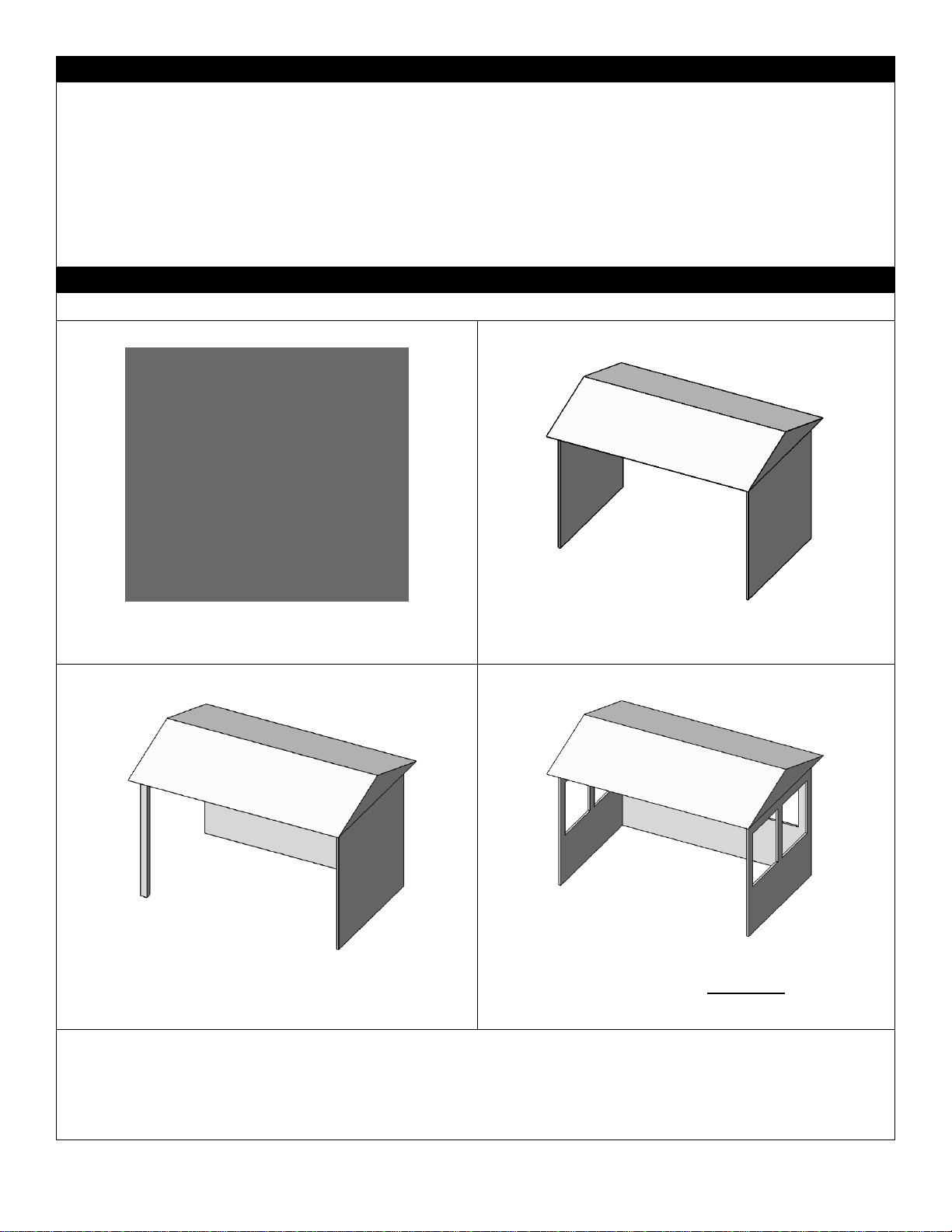
By definition, an outdoor space is not enclosed. Any area in which these appliances are used shall comply with
the structures shown below.
Locating Your Appliance – Outdoor Spaces
This appliance may be installed within the following structures:
1.
Walls on all sides (Minimum area of 96 square feet), but
with no overhead cover and at least one permanent
opening (doorway) at ground level.
2.
Within a partial enclosure that includes an overhead cover
and no more than two side walls.
3.
These side walls may be parallel, as in a breezeway, or at
right angles to each other.
4.
Within a partial enclosure that includes an overhead cover
and three side walls, as long as 30 percent or more of the
horizontal periphery of the enclosure is permanently open.
All models can be installed safely in a screened porch area within the following guidelines:
Minimum porch area is 96sq. feet with one side fully open.
A minimum of two (2) walls can be screened, but must be open to outside ventilation, with a minimum screen area of 64
sq. feet, and a minimum side wall height of 78” inches.
5
Page 6
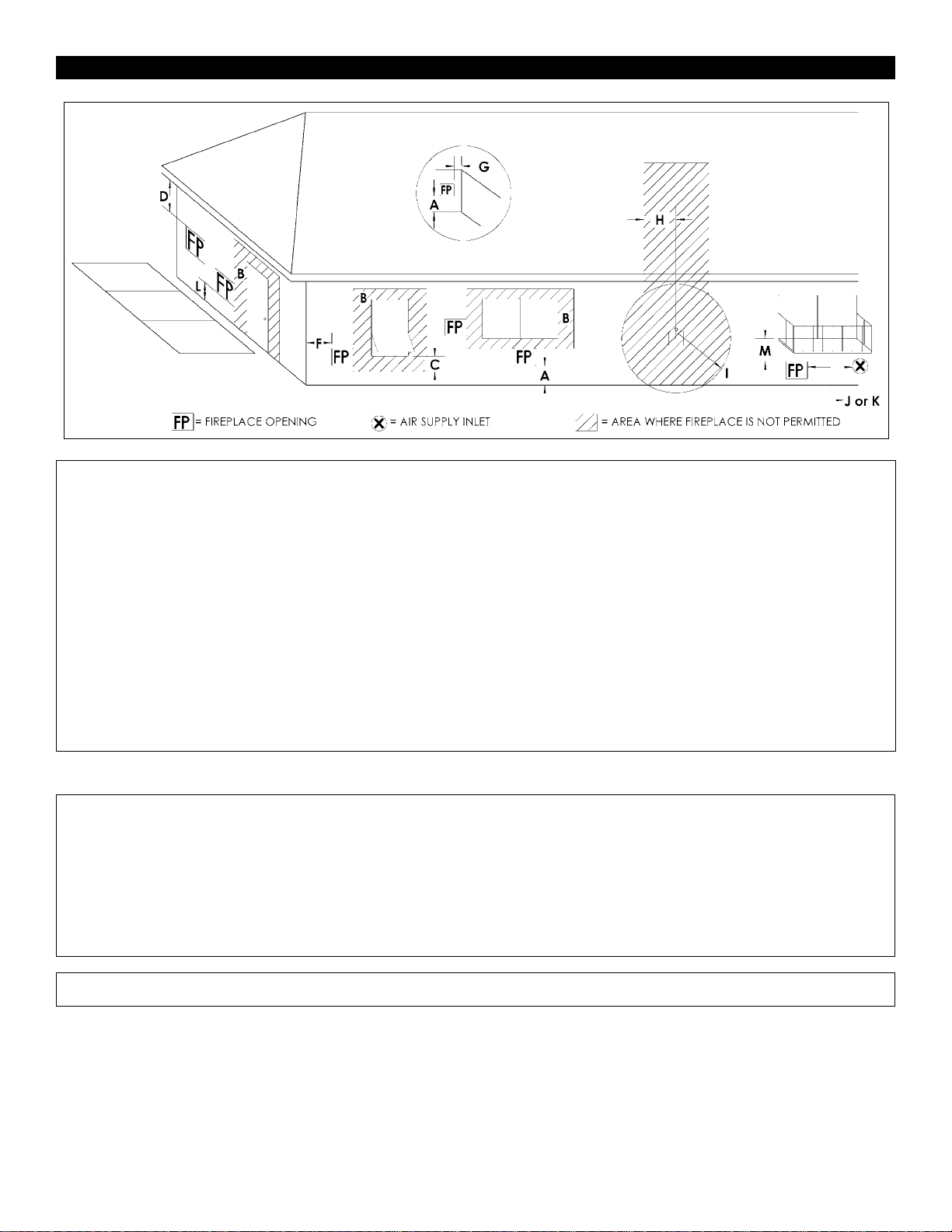
Clearance Specifications
A =
2in………….
Clearances above grade, veranda, porch,
deck or balcony.
I =
3ft (USA)……..
6ft (Canada)
Clearance to service regulator
vent outlet and electric service.
B =
12in…………
36in…………
Clearances to window or door that may be
opened, or to permanently closed window.
Vinyl windows or siding.
J =
9in (USA)…….
12in (Canada)
Clearance to non-mechanical air
Supply inlet to building or the
combustion air inlet to any other
appliance.
C =
12in…………
Clearance below an operable window.
K =
3ft (USA)…….
6ft (Canada)
Clearance to a mechanical air
supply inlet
D =
47in…………
60in…………
Vertical clearance to unventilated soffit or
to or to ventilated soffit located above the
fireplace.
Vinyl clad soffits.
L*=
54in………......
(See note 1)
Clearance above paved sidewalk
or a paved driveway located on
public property.
G =
3-1/2in…….
48in………..
Clearance to inside corner.
Vinyl windows or siding.
M**=
47in…………..
Clearance under veranda, porch,
deck, balcony or overhang.
H =
3ft. (Canada)
Not to be installed above a gas
meter/regulator assembly within 3ft
horizontally from the center line of the
regulator.
Not allowed….
Vinyl.
* A fireplace shall not open directly above a sidewalk or paved
driveway which is located between two single family
dwellings and services both swellings.
**Only permitted if veranda, porch, deck or balcony is fully
open on a minimum of 2 sides beneath the floor, or if the
screened porch guidelines are followed.
Note 1: Local codes or regulations may require different
clearances.
This appliance can be installed safely in a screened porch area
within the following guidelines:
Minimum porch area is 96sq. feet with one side fully open.
A minimum of two (2) walls can be screened, but must be open to
outside ventilation, with a minimum screen area of 64 sq. feet,
and a minimum side wall height of 78” inches.
Note: There may be some odor and small amounts of soot associated with burning the fireplace in a screened porch. Ensuring good
cross draft ventilation and routine maintenance of the fireplace will maximize comfort and cleanliness.
6
NOTE: Diagrams & Illustrations not to scale.
Page 7
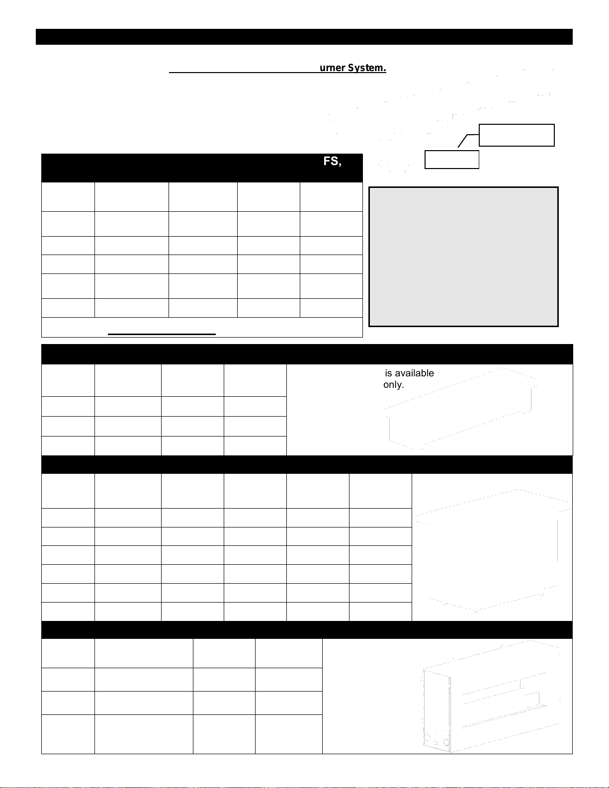
Outdoor Burners Basic Models and Applications
The Outdoor Burners (OB24, OB36, OB48, OB72, and OB96) are the basic component of the Barbara Jean
Series. These burners are a Complete Certified and Listed Burner System.
They consist of: -Burner
-Valve Control (Manual or Millivolt)
-Label
These burners can be placed into Custom Enclosures
which meet the specifications stated in the manual.
Burners for Custom Applications and Optional OFS,
OFT, and OFP Installations
LISTED
BURNER
MAP
Manual-LP
MAN
Manual-NG
MVP
Millivolt-LP
MVN
Millivolt-NG
OB24-
✔ c/w NG Orifice
✔
Conversion Kit
Required
✔
OB36-
✔ c/w NG Orifice
✔
Conversion Kit
Required
✔
OB48-
✔ c/w NG Orifice
✔
Conversion Kit
Required
✔
OB72-
N/A
N/A
Conversion Kit
Required
✔
OB96-
N/A
N/A
Conversion Kit
Required
✔
The following Approved Accessories can also be ordered:
Outdoor Fire Stand (OFS) Approved Accessory (Burner is Included)
LISTED
BURNER
OFS
Fire Stand
MAP
Manual-LP
MAN
Manual-NG
Outdoor Fire Stand is available
with a Manual Valve only.
OB24-
OFS24-
✔
✔
OB36-
OFS36-
✔
✔
OB48-
OFS48-
✔
✔
Outdoor Fire Tables (OLTN / OLTW) Approved Accessory (Burner is ordered separately)
LISTED
BURNER
OFT
Outdoor
Fire Table
MAP
Manual-LP
MAN
Manual-NG
MVP
Millivolt-LP
MVN
Millivolt-NG
Outdoor Fire Table
OB24-
OLTN24
✔
✔
Conversion Kit
Required
✔
OB24-
OLTW24
✔
✔
Conversion Kit
Required
✔
OB36-
OLTN36
✔
✔
Conversion Kit
Required
✔
OB36-
OLTW36
✔
✔
Conversion Kit
Required
✔
OB48-
OLTN48
✔
✔
Conversion Kit
Required
✔
OB48-
OLTW48
✔
✔
Conversion Kit
Required
✔
Outdoor Fireplace (OFP) Approved Accessory (Burner is included)
LISTED
BURNER
OFP
Outdoor Fireplace
MVP
Millivolt-LP
MVN
Millivolt-NG
Outdoor Fireplace
OB36-
OFP4336
S1 or S2
Conversion
Kit Required
✔
OB48-
OFP5548
S1 or S2
Conversion
Kit Required
✔
OB72-
OFP7972
S1 or S2
Conversion
Kit Required
✔
Label is attached
to Valve
VALVE
Burner systems may be connected
together in series (i.e. OB36MAP &
OB48MAP). See Custom Enclosures
section.
ALL LP MANUAL (MAP) VALVE SYSTEMS
ARE SHIPPED WITH AN ACCOMPANYING
ORIFICE FOR NG CONVERSION.
ALL MILLIVOLT VALVE SYSTEMS ARE
SHIPPED AS NG SYSTEMS (MVN) AND
REQUIRE A CONVERSION KIT FOR LP
CONVERSION.
7
Page 8
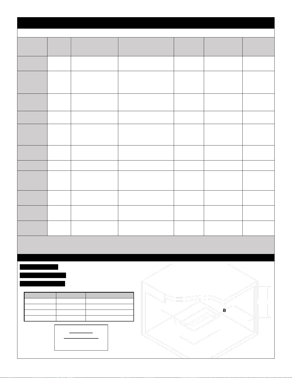
-Burners-
Burner Systems for Custom Applications, OB / OFS / OLTN / OLTW / OFP Models
Burner
System c/w
Valve
Valve
System
Stocked Burner
Conversion Kit shown
Burner (OB) Dimensions
for Custom Applications
(Add 1/8” per side for
tolerance)
Outdoor
Fire Stand
(OFS)
Outdoor Fire
Table
(OLTN or OLTW )
Outdoor
Fireplace
(OFP)
OB24MAP
Dante
Manual
LP Burner
(c/w NG Orifice)
7-1/2” wide x 26” long
x 2” tall
OFS24MAP
OLTN24
OLTW24
N/A
OB24MAN
Dante
Manual
NG Burner
For LP order
24OB-CKLP5 or
24OB-CKLP10
7-1/2” wide x 26” long
x 2” tall
OFS24MAN
OLTN24
OLTW24
N/A
OB24MVN
SIT
Millivolt
NG Burner
For LP order 24OB-
CKLP
7-1/2” wide x 26” long
x 2” tall
N/A
OLTN24
OLTW24
N/A
OB36MAP
Dante
Manual
LP Burner
(c/w NG Orifice)
7-1/2” wide x 38” long
x 2” tall
OFS36MAP
OLTN36
OLTW36
N/A
OB36MAN
Dante
Manual
NG Burner
For LP order
36-48OB-CKLP5 or
36-48OB-CKLP10
7-1/2” wide x 38” long
x 2” tall
OFS36MAN
OLTN36
OLTW36
N/A
OB36MVN
SIT
Millivolt
NG Burner
For LP order
36OBCKLP
7-1/2” wide x 38” long
x 2” tall
N/A
OLTN36
OLTW36
OFP4336S1
OFP4336S2
OB48MAP
Dante
Manual
LP Burner
(c/w NG Orifice)
7-1/2” wide x 50” long
x 2” tall
OFS48MAP
OLTN48
OLTW48
N/A
OB48MAN
Dante
Manual
NG Burner
For LP order
36-48OB-CKLP5 or
36-48OB-CKLP10
7-1/2” wide x 50” long
x 2” tall
OFS48MAN
OLTN48
OLTW48
N/A
OB48MVN
SIT
Millivolt
NG Burner
For LP order
48OB-CKLP
7-1/2” wide x 50” long
x 2” tall
N/A
OLTN48
OLTW48
OFP5548S1
OFP5548S2
OB72MVN
SIT
Millivolt
NG Burner
For LP order
72OB-CKLP
7-1/2” wide x 74” long
x 2” tall
N/A
N/A
OFP7972S1
OFP7972S2
OB96MVN
SIT
Millivolt
NG Burner
For LP order
96OB-CKLP
7-1/2” wide x 98” long
x 2” tall
N/A
N/A
N/A
Burner systems may be connected together in series (i.e. OB36MAP & OB48MAP). See Custom Enclosures section.
LP MANUAL (MAP) VALVE SYSTEMS ARE SHIPPED WITH ACCOMPANYING ORIFICE FOR NG CONVERSION.
MILLIVOLT SYSTEMS ARE SHIPPED AS NG SYSTEMS (MVN) AND REQUIRE A CONVERSION KIT FOR LP CONVERSION.
Locating Your Appliance –Minimum Clearances to Combustibles
Outdoor Burners (OB24 / 36 / 48 / 72 / 96)
Outdoor Fire Stands (OFS24 / 36 / 48)
Outdoor Fire Tables (OLTN / OLTW24 / 36 / 48)
Clearance
Dimension
Measured From:
A: Side wall
24”
Side of Burner Tray
B: End wall
12”
End of Burner Tray
C: Ceiling
49-1/2”
Top of Burner Tray
D: Floor
8”
Top of Burner Tray
A
C
D
WARNING
-RISK OF FIRE-
All minimum clearances
must be adhered to.
CEILING
8
Page 9
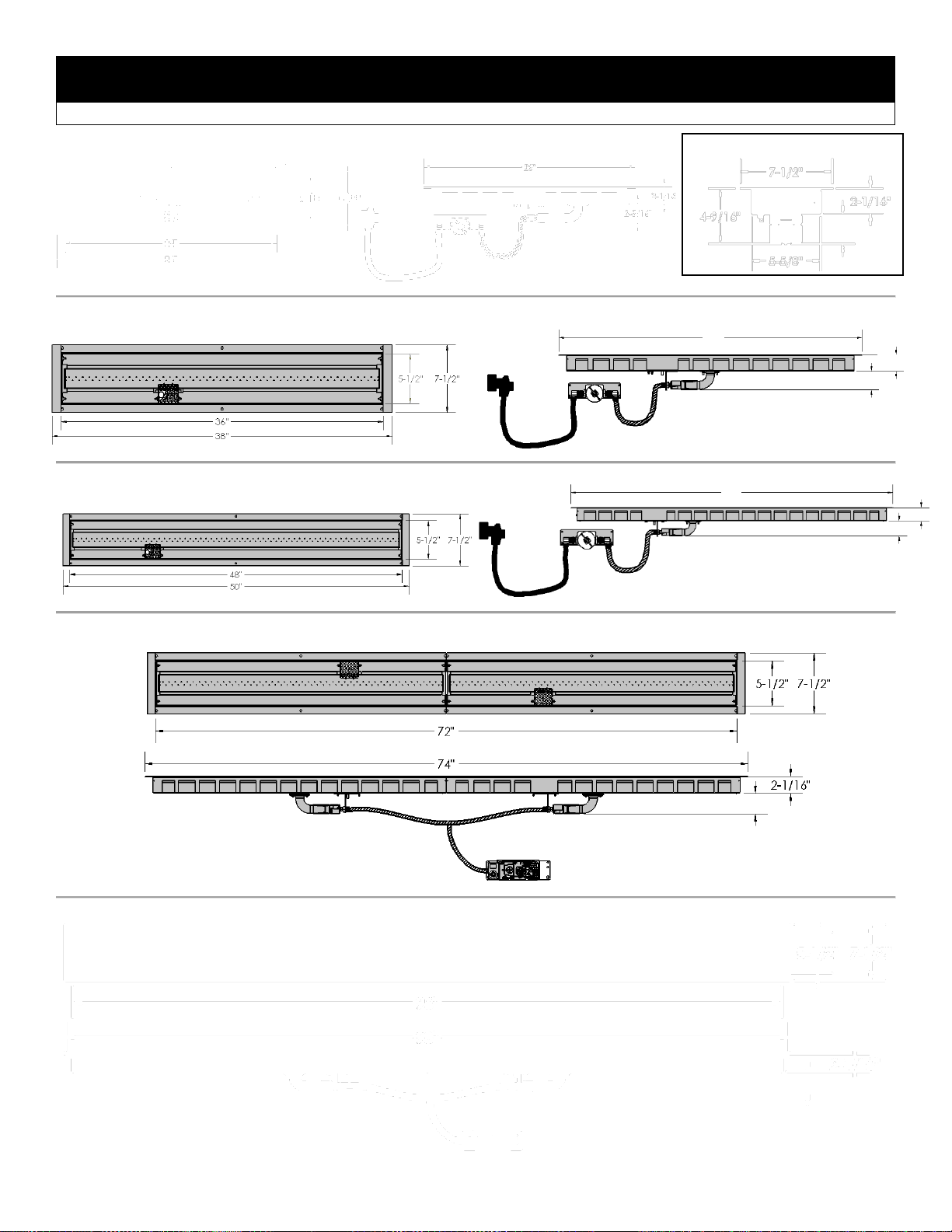
Certified Burners with Label
Dimensions OB24 / OB36 / OB48 / OB72 / OB96 (Outdoor Burners)
END VIEW- ALL BURNERS
2-1/16”
2-5/16”
38”
2-5/16”
2-1/16”
50”
2-5/16”
2-5/16”
2-5/16”
9
OB24 BURNER
OB36 BURNER
OB48 BURNER
OB72 BURNER
OB96 BURNER
Page 10
OB Burners – Unpacking and Setup – Manual Valve Systems
.
STEP 1: Insert Burner Orifice into mixing sleeve and attach Orifice
Retainer Bracket with [2] 1/2” DT Screws. Then insert Electrode Mount
Plate and Sparker into Burner and install with [2] 1/2” DT Screws.
STEP 2: Install Burner with attached Valve
System into structure.
For Outdoor Fire Tables (OFT) refer to
OFT Burner Installation Instructions.
For Outdoor Fireplaces (OFP) refer to OFP
Burner Installation Instructions.
Refer to Custom Enclosures Section for
Custom Enclosures.
NOTE: Filler Strips must be installed
before media is placed into burner.
Parts List: OB24 / OB36 / OB48 MAP/MAN
[1] Burner, c/w [1] Pilot Shield, [2] Ends, [3] Filler Strips
[1] Manual Valve System (c/w Regulator and 5ft Hose for LP
Systems)
[1] Push Button Igniter c/w wire and Sparker
[1] Valve Key
[1] Key Way Installation Tool
[1] Brass Orifice for NG Conversion (LP Systems)
[1] Tank Retainer (LP Systems)
[1] Hardware Bag: [8] 1/2” DT Screws, [4] #6 Black Screws, [2]
#10 Woodscrews
[3] Filler Strips (See Below)
Orifice Retainer
Bracket
Electrode Mount Plate
and Sparker
24OB – 23-9/16”
36OB – 35-9/16”
48OB – 47-9/16”
24OB – 10-5/8”
36OB – 10-5/8”
48OB – 10-5/8”
24OB – 10-5/8”
36OB – 22-5/8”
48OB – 34-5/8”
FILLER STRIPS:
Long Flange Up
Short Flange Down
Qty [4] 1/2” DT Screws
to attach Valve
NG Conversion Orifices
(Included with MAP Burners)
OB24MAP - #40
OB36MAP - #31
OB48MAP - #30
Air Shutter = 1/16”- NG
Air Shutter = Full Open- LP
10
Page 11
OB Burners – Unpacking and Setup – Millivolt Valve Systems
STEP 1 (For OB72 & OB96 only):
Connect Burners using [2] 10-24 x
1/2” bolts. Set Cover Clip over joined
burner ends.
STEP 2: Insert Orifice(s)
into mixing sleeve(s) and
install bracket(s) with [4]
1/2” DT Screws. Then
insert Pilot Assembly into
one Burner and attach with
[2] 1/2” DT Screws.
Attach Pilot Opening Cover
in the other Burner with [2]
1/2”DT Screws.
Air Shutter = 1/16”- NG
Air Shutter = Full Open- LP
STEP 3: Install Burner with attached Valve System into structure.
For Outdoor Fire Tables (OFT) refer to OFT Burner Installation Instructions page.
For Outdoor Fireplaces (OFP) refer to OFP Burner Installation Instructions page.
For Custom Enclosures refer to Custom Enclosures Section.
NOTE: Filler Strips must be installed before media is placed into burner.
Parts List: OB72 / OB96MVN
[2] Burners, c/w [2] Pilot Shields, [2] Ends, [6] Filler Strips
[1] Millivolt Valve System (c/w [2] Orifice Assemblies and [1] Pilot
Assembly)
[1] Piezo Button Igniter c/w wire and Sparker
[1] On/Off Rocker Switch (installed on valve)
[1] Pilot Opening Cover
[1] Hardware Bag: [12] 1/2” DT Screws, [8] #6 Black Screws, [2]
10-24 x 1/2” Bolts c/w Star Nuts
[6] Filler Strips
[1] Cover Clip
24OB – 23-9/16”
36OB – 35-9/16” (x 2 for OB72)
48OB – 47-9/16” (x 2 for OB96)
24OB – 10-5/8”
36OB – 10-5/8” (x 2 for OB72)
48OB – 10-5/8” (x 2 for OB96)
24OB – 10-5/8”
36OB – 22-5/8” (x 2 for OB72)
48OB – 34-5/8” (x 2 for OB96)
Connect Electrode
Wire to Piezo.
Connect On/Off
Switch to TP and
TH Terminals.
Connect Electrode Wire to
Piezo.
Connect On/Off Switch to
TP and TH Terminals.
Install Pilot Assembly and
Orifice Bracket [4 Dt Screws].
Cover Clip
Pilot Assembly is
installed from
bottom of Burner
Tray – but can be
serviced from the
Top.
Parts List: OB24 / OB36 / OB48MVN
[1] Burner, c/w [1] Pilot Shield, [2] Ends, [3] Filler Strips
[1] Millivolt Valve System (c/w Orifice Assembly and Pilot Assembly)
[1] Piezo Button Igniter c/w wire and Sparker
[1] On/Off Rocker Switch (Installed on valve)
[1] Hardware Bag: [8] 1/2” DT Screws, [4] #6 Black Screws
[3] Filler Strips (See Below)
Orifice
Retainer
Bracket
Pilot Opening
Cover
FILLER STRIPS:
[Qty 4] 1/2”
DT Screws
to attach
valve to
appliance
Long Flange Up
Short Flange
Down
[Qty 2] 1/2”
DT Screws
[Qty 2] 1/2”
DT Screws
11
Page 12
-Custom Enclosures-
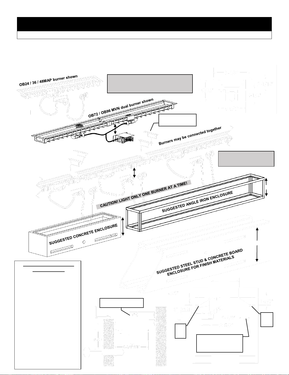
OB24 / 36 / 48 / 72 / 96 (Must be non-combustible)
Multiple burners can be connected together in series. ENCLOSURES MUST BE NON-COMBUSTIBLE. Enclosures
3” MIN
3” MIN
5-3/4”
Required Openings for
Stock Burners
OB24 – 5-3/4” x 24-1/2”
OB36 – 5-3/4” x 36-1/2”
OB48 – 5-3/4” x 48-1/2”
OB72 – 5-3/4” x 72-1/2”
OB96 – 5-3/4” x 96-1/2”
Burners may be connected
together in any combination.
When connecting additional
burners, add desired lengths
(24”, 36”, 48”, 72”, 96”) plus
Required Opening for total
opening (e.g. 24” + 72-1/2” +
24” = 120-1/2”).
NOTE: Flame height will be
noticeably higher on OB48
burners. This can be manually
adjusted.
Remove ends when
connecting burners.
END VIEW
ALL BURNERS
Maximum height of
media is 1” above tray.
LED Light Strips must be
at least 1-5/8” below and
2-5/8” away from Burner
Tray.
LED
Light
Strip
LED
Light
Strip
8” MIN
8” MIN
8” MIN
Burner Tray must
be supported.
REFER TO Enclosures for LP
(Propane) Gas Supply
Systems
NOTE: All Gas Controls and
connections must be readily
removable, supported, or accessible.
12
shown are suggestions only. Refer to Clearance to Combustibles section of manual.
NOTE: all manual valve systems are shipped as LP systems (MAP) with accompanying orifice for NG conversion.
All millivolt valve systems are shipped as NG systems (MVN) and require a conversion kit for LP conversion.
NOTE: For propane installations see Enclosures for LP (Propane) Gas Supply Systems.
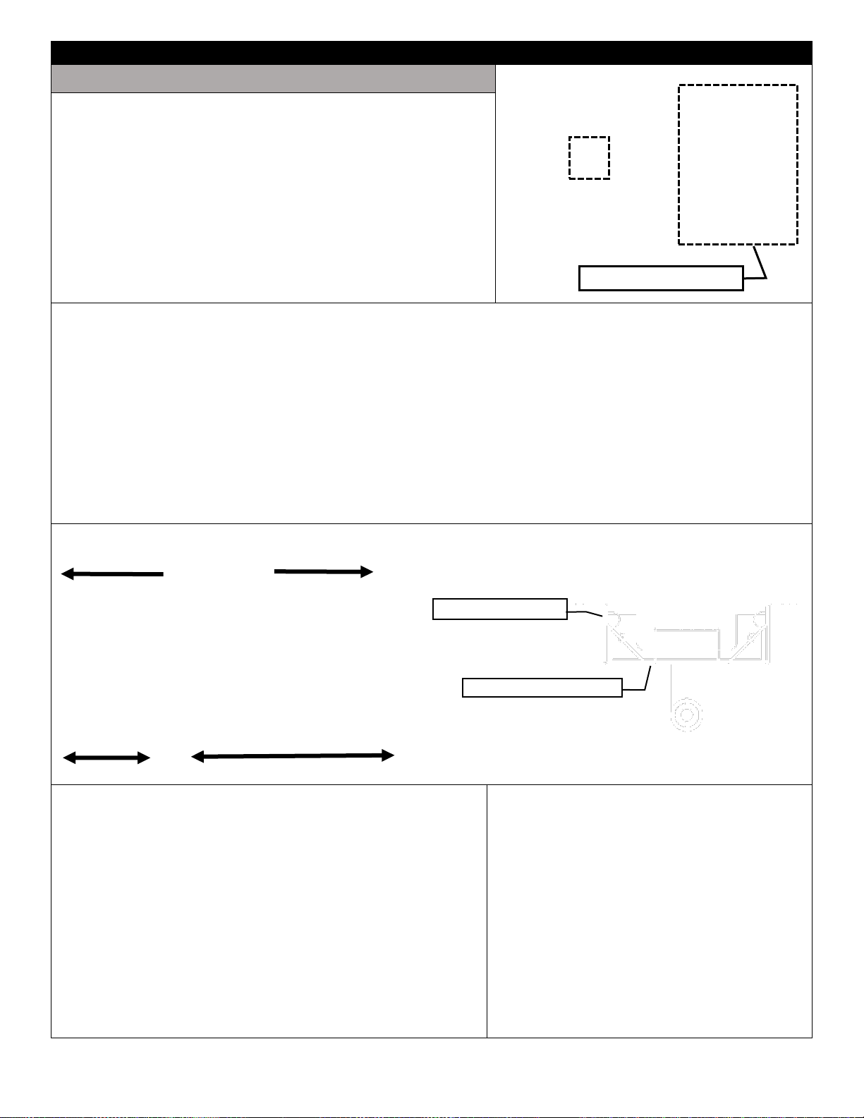
Page 13
Optional LED Lighting – Custom Enclosures
Please follow the current ANSI/NFPA 70 National Electrical Code in the USA and CAN/CSA C22.1 Canadian
National Electrical Code in Canada.
⚠ WARNING
Electrical Grounding Instructions
This appliance is equipped with a three prong (grounding)
plug for your protection against shock hazard and should be
plugged directly into a properly grounded three-prong
receptacle. Do not cut or remove the grounding prong from
this.
The fireplace receptacle must be connected to an
external GFI protected outlet installed near the fireplace.
Before Servicing
1. Ensure all power supply is shut off.
2. Label all wires prior to disconnecting when servicing
control. Wiring errors can cause improper and
dangerous operation.
SIDE VIEW
CUSTOM
ENCLOSURE
-Junction Box-
Must be connected to
an external GFI outlet
JUNCTION
BOX
LED
CONTROL
BOX
LED LIGHT
STRIP
LED LIGHT
STRIP
13
NOTE: If appliance is directly connected to an electrical supply, it must be anchored using anchor points provided in
bottom of appliance. Use cord and wire restraints provided also.
Page 14
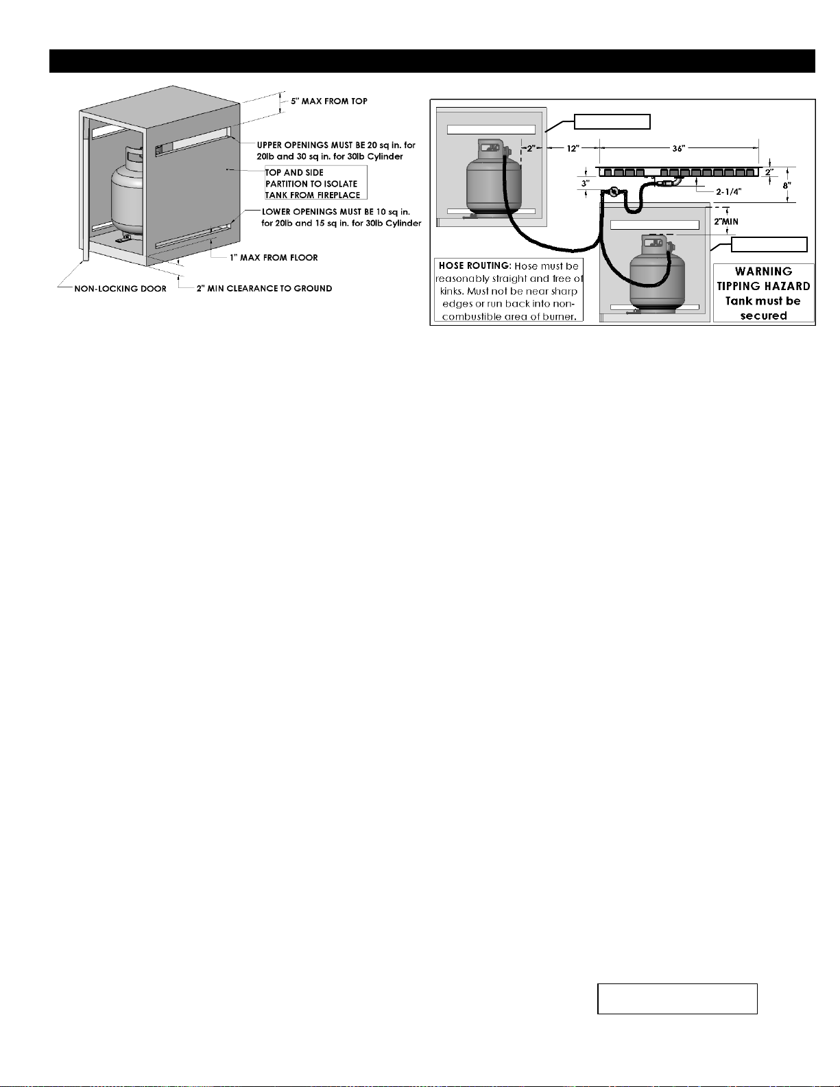
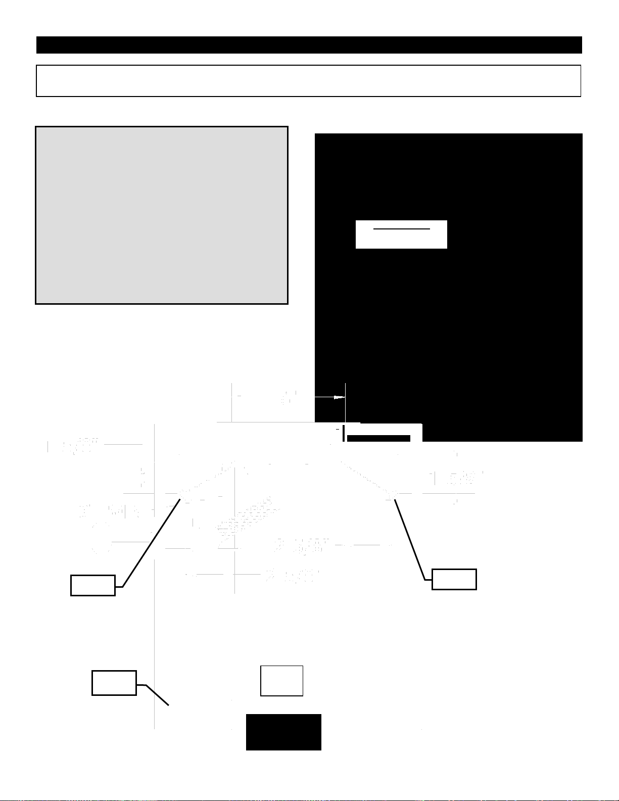
Enclosures for LP (Propane) Gas Supply Systems
LP cylinder with retention
device attached.
Combustible
Combustible
14
If you build an enclosure for an LP gas cylinder you must
follow these specifications. You must also follow local
codes.
An enclosure for an LP-gas cylinder shall be ventilated by
openings at both the upper and lower levels of the
enclosure. This shall be accompanied by one of the
following:
a. One side of the enclosure shall be completely open; or
b. For an enclosure having four sides, a top, and a bottom:
1. At least two ventilation openings shall be provided in the
sidewalls of the enclosure, located within 5 in (217 mm) of
the top of the enclosure, equally sized, spaced at a
minimum of 90 degrees (1.57 rad), and unobstructed. The
opening(s) shall have a total free area of not less than
1square inch per pound (14.2 cm2Ckg) of stored fuel
capacity.
2. Ventilation opening(s) shall be provided at floor level of
the enclosure and shall have a total free area of not less
than 1/2 square inches per pound (7.1 cm2Ckg) of stored
fuel capacity. If ventilation openings at floor level are in a
sidewall, there shall be at least two openings. The bottom
of the openings shall be 1 in (25.4 mm) or less from the
floor level and the upper edge no more than 5 in (127
mm) above the floor level. The openings shall be equally
sized, spaced at a minimum of 90 degrees (1.57 rad),
and unobstructed.
3. Every opening shall have minimum dimensions so as to
permit the entrance of a 1/8 in (3.2 mm) diameter rod.
4. Ventilation openings in sidewalls shall not communicate
directly with other enclosures of the appliance.
The cylinder valve shall be readily accessible for hand
operation. A door on the enclosure to gain access to the
cylinder valves is acceptable, provided it is non-locking and
can be opened without the use of tools. Designs using a
cover to gain access to the cylinder and cylinder valve shall
be provided with handles or equivalent at a minimum of 180
degrees apart to facilitate lifting of the cover.
The enclosure for the LP-gas cylinder shall isolate the
cylinder from the burner compartment to provide:
a. Shielding from radiation;
b. A flame barrier; and
c. Protection from foreign material.
There shall be a minimum clearance of 2 in (50.8 mm)
between the floor of the non-disposable LP-gas cylinder
enclosure and the ground.
The design of the fireplace shall be such that:
a. A non-disposable LP-gas cylinder can be connected,
disconnected, and the connections inspected and tested
outside the cylinder enclosure; and
b. Those connections which could be disturbed when
installing the cylinder in the enclosure can be leak tested
inside the enclosure.
Be certain to mount or set the LP-gas cylinder on a flat
stable surface and retain it to prevent it from tipping.
Purge the gas supply line of any trapped air prior to the
first firing of the unit.
WARNING: During the initial purging and subsequent
lightings, NEVER allow gas valve to remain in "OPEN"
position without first placing a burning match on the top
of the burner.
Test fire the unit after referring to the SAFETY
INFORMATION and LIGHTING INSTRUCTIONS.
If
LP-Gas outdoor fire
pits
are used
continuously after a
couple
of
hours,
you
could
see the
possibility of the
decreasing
this
happens,
the
control valve
the tank
wait a
valve
couple
flame
in size. If
turn off
and
and
of
hours
before lighting again
or switch
tanks. The
tank is
to the
being taken
propane
propane
freezing
volume
up due
of gas
out of the
tank.
Page 15
Fire Stands – Approved Accessory
OFS Series Dimensions (Outdoor Fire Stand)
OFS24MAP / OFS24MAN
15
OFS36MAP / OFS36MAN
OFS48MAP / OFS48MAN
Page 16
OFS Outdoor Fire Stands – Unpacking and Setup
Parts List: OFS24 / OFS36 / OFS48 – MAP/MAN
[1] OFS Outdoor Fire Stand c/w Burner, Valve System and 10ft LP
Hose & Regulator (Installed)
[3ea] Filler Strips
[1] Push Button Igniter (AAA Battery not included) c/w Wire and
Sparker (Installed)
[1] Valve Key
[1] Key Way Installation Tool
[1] Brass Orifice for NG Gas Conversion (LP Systems)
[1] Tank Retainer, [2ea] Wood Screws (LP Systems)
OFS24 Shown – Ready for Media Placement.
See Media Section of Manual for Options.
END VIEW – Outdoor Fire Stand
FILLER STRIPS:
24OB – 23-9/16”
36OB – 35-9/16”
48OB – 47-9/16”
ALL UNITS – 10-5/8”
24OB – 10-5/8”
36OB – 22-5/8”
48OB – 34-5/8”
OFP Bottom View
(MAP System Shown)
INCLUDED WITH MAP (PROPANE)
BURNER SYSTEMS ONLY
Long Flange at Top
Short Flange at Bottom
BURNER END VIEW
Valve Control
Push Button Igniter – Unscrew and insert AAA
Battery here.
16
Page 17
Fire Tables –Approved Accessory
OLTN24 and OLTW24 Dimensions (Outdoor Fire Table)
OLTN24
BURNER OPTIONS:
OB24MAP (c/w #40 Orifice for NG)
OB24MAN (Order 24OB-CKLP5 for LP)
OB24MVN (Order 24OB-CKLP for LP)
OLTW24
BURNER OPTIONS:
OB24MAP (c/w #40 Orifice for NG)
OB24MAN (Order 24OB-CKLP5 for LP)
OB24MVN (Order 24OB-CKLP for LP)
17
Page 18

Fire Tables –Approved Accessory
OLTN36 and OLTW36 Dimensions (Outdoor Fire Table)
OLTN36
BURNER OPTIONS:
OB36MAP (c/w #31 Orifice for NG)
OB36MAN (Order 36-48OB-CKLP5 for LP)
OB36MVN (Order 36OB-CKLP for LP)
OLTW36
BURNER OPTIONS:
OB36MAP (c/w #31 Orifice for NG)
OB36MAN (Order 36-48OB-CKLP5 for LP)
OB36MVN (Order 36OB-CKLP for LP)
18
Page 19

Fire Tables –Approved Accessory
OLTN48 and OLTW48 Dimensions (Outdoor Fire Table)
OLTN48
BURNER OPTIONS:
OB48MAP (c/w #30 Orifice for NG)
OB48MAN (Order 36-48OB-CKLP5 for LP)
OB48MVN (Order 48OB-CKLP for LP)
OLTW48
BURNER OPTIONS:
OB48MAP (c/w #30 Orifice for NG)
OB48MAN (Order 36-48OB-CKLP5 for LP)
OB48MVN (Order 48OB-CKLP for LP)
19
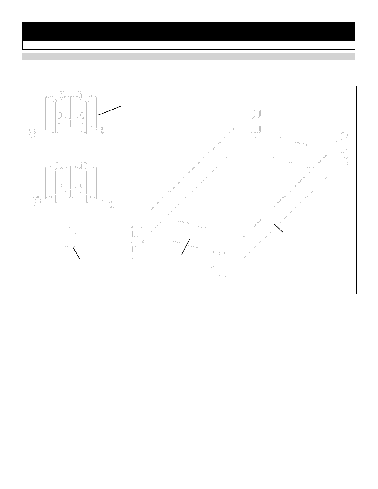
Page 20

Fire Tables -Assembly-
OUTDOOR FIRE TABLES: OLTN24, OLTW24, OLTN36, OLTW36, OLTN48, OLTW48
Tools Required: 1/4” Hex Driver c/w 4” Extension or 1/4” Hex Screwdriver
NOTE: Two people are required to lift this assembly.
Step One: Lay Table Top upside down on a flat non-
abrasive surface.
Step Two: Form Tank Shield into shape and attach to
one end of Table Top with [4] DT Screws. NOTE: There
will be two Tank Shields for 36” and 48” models.
Step Three:
Carefully
place Table
Body onto
Table Top
and attach
with [4 or 6]
bolts.
NOTE: Tank
Brace &
Tank Shield
must be on
the same
side as the
Tank Mount Hole.
Step Four: Install Tank
Brace with Washer and
Thumbscrew.
Carefully lift and place
Fire Table upright.
Install Doors using [2]
DT Screws each.
NOTE: Doors may be
installed on either left
or right side.
Burner Lid
Tank Shield
Table Top
Table Top
Table Body
Tank
Mount
Hole
Tank
Guard
Table Top
Outer Trim Ring
Table Top
Table Body
Tank Shield
Door
Door
Parts List:
BOX 1:
[1ea.] Burner Lid
[1ea.] Outer Trim Ring
[1ea.] Table Top
[1ea.] Tank Shield, [2ea.] for 36” & 48”
BOX 2:
[1 ea.] Table Body
[2 ea.] Door
[1 ea.] Tank Brace
Hardware:
[8 ea.] DT Screws, [12ea.] for 36” & 48”
[4 ea.] Bolts 8-32 x 1”, [6ea.] for 36” & 48”
Tank
Brace
Tank Brace
Tank
Shield
20
Page 21

OLTN and OLTW Burner Installation
Place Burner and Valve assembly into opening in table top. Attach Valve Mount Bracket on valve to Mount Plate on
OB Burner and Valve Assembly
Valve Mount Bracket
Valve Mount Plate
DT Screw
DT Screw
DT Screw
DT Screw
#6 Black Screws
#6 Black Screws
Push Button Igniter
Location
Valve Key storage
on inside of door
ON/OFF Switch
Location
Electronic Spark
Module
4 DT Screws
to attach
Valve to
Appliance
See Electronic Spark Assist Page
Piezo
Igniter
On/Off
Switch
21
table.
MANUAL VALVE SETUP OPTIONAL ELECTRONIC SPARK ASSIST
Page 22

Optional LED Lighting - OLTN / OLTW Outdoor Fire Tables
Please follow the current ANSI/NFPA 70 National Electrical Code in the USA and CAN/CSA C22.1 Canadian
National Electrical Code in Canada.
⚠ WARNING
Electrical Grounding Instructions
This appliance is equipped with a three prong (grounding)
plug for your protection against shock hazard and should be
plugged directly into a properly grounded three-prong
receptacle. Do not cut or remove the grounding prong from
this.
The fireplace receptacle must be connected to an
external GFI protected outlet installed near the fireplace.
Before Servicing
1. Ensure all power supply is shut off.
2. Label all wires prior to disconnecting when servicing
control. Wiring errors can cause improper and
dangerous operation.
SIDE VIEW
OLTN / OLTW
JUNCTION
BOX
TOP VIEW
OLTN / OLTW
-Junction Box-
Must be connected to
an external GFI outlet
ANCHOR
POINT
ANCHOR
POINT
LED
CONTROL
BOX
ANCHOR
POINT
ANCHOR
POINT
LED LIGHT
STRIP
LED LIGHT
STRIP
LED
CONTROL
BOX
22
NOTE: If appliance is directly connected to an electrical supply, it must be anchored using anchor points provided in
bottom of appliance. Use cord and wire restraints provided also.
Page 23

20lb Cylinder Installation - Fire Table - Custom Installations
Fire Tables -20LB Cylinder In Unit-
⚠ Only a 20LB LP Cylinder may be used inside the Fire Table Enclosure.
NOTE: Cylinders acceptable for use inside this appliance must be compatible with the retention means shown here.
The LP gas supply cylinder used with LP models
must be constructed and marked in accordance
with the specifications for LP-gas cylinders of the
U.S. Department of Transportation (DOT)
Specifications for LP-Gas Cylinders, or the
Standard for Cylinders, Spheres and Tubes for
Transportation of Dangerous Goods and
Commission, CAN/CSA-B339, as applicable.
The LP gas supply cylinder used with LP models
must be provided with a listed overfilling
prevention device.
The pressure regulator and hose assembly
supplied with LP models (PN# 27FP-900FF) must
be used. Replacement pressure regulators and
hose assemblies must be those specified in this
manual.
Always check for gas leaks with a soap and water
solution. DO NOT USE OPEN FLAME FOR LEAK
TESTING.
When an LP model is not in use, the LP-gas must
be turned off at the supply cylinder.
CUSTOM INSTALLATIONS
TANK RETAINER - Included with all MAP Burners and LP
Conversion Kits
1. Connect foot ring of 20lb
Cylinder to Tank Retainer with
thumbscrew.
2. Fasten Tank Retainer to
mounting surface.
3. Concrete anchor
required for concrete
surface (not supplied).
Foot Ring Drops
into Round Hole
Replace Tank Brace.
Slide over Protective
Collar of 20lb cylinder
and tighten.
Tank Retainer for Custom
Installations.
NOT USED ON FIRE TABLES.
Installation of 20lb Cylinder
into Fire Tables:
Remove Top Clamp.
Connect 20lb cylinder to
regulator.
Place 20lb cylinder into
Fire Table as shown.
Secure 20lb cylinder with
Tank Brace as shown.
Tank Brace
23
Page 24

Outdoor Fireplaces
OFP4336S1 and OFP4336S2 Dimensions (Outdoor Fire Place)
OFP4336S1 (Millivolt/Natural Gas)
Convert to LP with Conversion Kit
36OB-CKLP
OFP4336S2 (Millivolt/Natural Gas)
Convert to LP with Conversion Kit
36OB-CKLP
24
Page 25

Outdoor Fireplaces
OFP5548S1 and OFP5548S2 Dimensions (Outdoor Fire Place)
OFP5548S1 (Millivolt/Natural Gas)
Convert to LP with Conversion Kit
48OB-CKLP
OFP5548S2 (Millivolt/Natural
Gas) Convert to LP with
Conversion Kit 48OB-CKLP
25
Page 26

Outdoor Fireplaces
OFP7972S1 and OFP7972S2 Dimensions (Outdoor Fire Place)
OFP7972S1
(Millivolt/Natural
Gas) Convert to LP
with Conversion Kit
72OB-CKLP
OFP7972S2
(Millivolt/Natural
Gas) Convert to LP
with Conversion Kit
72OB-CKLP.
26
Page 27

Outdoor Fireplaces – Handling Unit – OFP4336 / OFP5548 / OFP7972
2 x 4
2 x 4
Lift Here
Lift Here
Lift Here
27
⚠ CAUTION: UNIT IS EXTREMELY HEAVY
Ensure that fireplace is properly supported when handling.
Tab cutouts on the faces of the appliance can be used to assist with handling and locating fireplace.
Cutouts are for Hand use or 2 x 4 use.
Lift Tabs are for crane use.
Page 28

OFP4336 / 5548 / 7972 S1 or S2 – Adjustable Support Guide
-Hearth Flush With Fireplace Opening-
Adjustable Support Guides on the sides of the fireplace can be used to assist installation.
NOTE: Support Guide is
NOT load bearing. Bottom
of fireplace MUST be
supported.
Set Support Guides at
desired height and
attach with DT
Screws.
Support Guide
Support Guide
Set to desired height.
Ledge Stone
Base
Support Guide
Support Guide
Base
Bottom of fireplace must be
supported.
28
Page 29

Outdoor Fireplaces
OPTIONAL FRAMING: OFP4336 / OFP5548 / OFP7972 (S1 & S2)
4336 / 5548 / 7972-S1 Single Sided Framing
4336 / 5548 / 7972-S2 See Through Framing
1/2” Plywood
Non-Combustible Facing
1/2” Plywood
Exterior Facing
Fold Nailing Tabs
back onto framing.
Fold Nailing Tabs
back onto
framing.
SIDE
OF
UNIT
RIGHT
SIDE OF
UNIT
Back of Unit
Install Non-combustible Header
Panel.
Fold Standoffs into position and
fasten in place with Screws.
Use Nailing Tabs to fasten Unit to
framing.
Use Nailing Tabs to fasten Unit
to framing.
29
Page 30

Outdoor Fireplaces CLEARANCES: OFP4336 / OFP5548 / OFP7972 (S1 & S2)
The sides and top of the front face of these appliances must be covered with non-combustible materials only.
Sides and Top of Front Faces of OFP4336 / OFP5548 / OFP7972 S1 and
S2 Fireplaces can be covered by Non-combustible materials only (i.e. brick,
stone, tile, concrete board, etc.).
Mantel Dimensions are from front
face or Non-Combustible Facing
Materials covering fireplace.
FLOOR INSTALLATION
ELEVATED INSTALLATION
Clearance
Dimension
Measured From:
A: Side wall
8-1/2”
Side of fireplace opening
B: Ceiling
61”
Bottom of Unit
C: Ceiling
35”
Top of fireplace opening
D: Mantel Height- Bottom
35-1/2”
Bottom of Unit
E: Mantel Height- at 10” Depth
45-1/2”
Bottom of Unit
Combustibles In Front of Unit
36”
Face or Facing of Fireplace
Top, Sides and Back of Appliance
0”
Standoffs
ALCOVE
Alcove Depth- All Units
36”
Face or Facing of Fireplace
Alcove Width- OFP4336S1 & S2
60” = Fireplace Opening (43”) plus Side wall Dim A (8-1/2”) x 2
Alcove Width- OFP5548S1 & S2
72” = Fireplace Opening (55”) plus Side wall Dim A (8-1/2”) x 2
Alcove Width- OFP7972S1 & S2
96” = Fireplace Opening (79”) plus Side wall Dim A (8-1/2”) x 2
A
A B D C E
COMBUSTIBLE
COMBUSTIBLE
WARNING
-RISK OF FIRE-
All minimum clearances
must be adhered to.
ALCOVE
DEPTH
WIDTH
Fireplace
Opening
SIDE VIEW
⚠ WARNING
Combustible Objects on Non-Combustible Mantel
Combustible objects must not be placed on a Non-
combustible Mantel unless the mantel meets the
dimensional requirements for a Combustible Mantel.
Determine whether your mantel conforms to the
requirements of a Combustible Mantel.
COMBUSTIBLE
NON-COMBUSTIBLE
COMBUSTIBLE
NON-COMBUSTIBLE
OFP4336 / OFP5548 / OFP7972 S1 SHOWN
30
Page 31

Surround Installation OFP43SS / OFP55SS / OFP79SS
Parts List:
-Surround Frame [1 pc]
-Side Filler Panels [2 pc] (1LH & 1RH)
-Stainless Steel Screws ([2] for OFP43SS,
[3] for OFP55SS & OFP79SS)
STEP 1: Place bottom of Side Filler into gap at corner of
opening.
STEP 2: Push Side Filler into place. Repeat procedure for
other side.
STEP 3: Hook Surround Frame onto Lower Edge of
fireplace opening.
STEP 4: Push Surround Frame into place and attach with
screws into top lip of opening.
LEFT
RIGHT
TOP
RIGHT
CORNER
HOOK ONTO LOWER EDGE
31
Page 32

Weather Cover Installation OFP43WC / OFP55WC / OFP79WC
PARTS LIST: 1 Weather Cover
-WEATHER COVER CAN BE USED WITH OR WITHOUT SURROUND-
STEP 1: Insert left side of Weather Cover into fireplace
opening.
STEP 2: Insert right side of Weather Cover into fireplace
opening. Slide to the right until gap is closed.
Weather Cover is installed.
16-1/16”
44” for OFP36WC
56” for OFP48WC
80” for OFP72WC
32
Page 33

OFP4336 / OFP5548 / OFP7972 Wind Guard Glass Installation
Wind Guard Glass must be installed for safety and in order for unit to function properly.
Stainless Steel Parts And Accessories
Wind Guard
Glass
Glass Mount
Bracket
33
Step one: Place Wind Guard Glass into Glass Mount Brackets.
Step two: Center Wind Guard Glass in appliance and tighten screws in Glass Mount Brackets. Do NOT over tighten.
NOTE: The protective wrap on stainless steel parts is best removed at room temperature. A hair dryer may be
helpful.
Cleaning Stainless Steel
Stainless steel tends to oxidize or stain in the presence of chlorides and sulfides, particularly in coastal areas and other
harsh environments, such as the warm, highly humid atmosphere around pools and hot tubs. These stains could be
perceived as rust, but can be easily removed or prevented. To provide stain prevention and removal, wash all stainless
steel surfaces every 3-4 weeks or as often as required with fresh water and/or stainless steel cleaner.
Notes on Cleaning Stainless Steel Surfaces: Do not use abrasive cleaners or steel wool on any painted, or stainless
steel parts. Doing so will scratch the finish. Exterior surfaces should be cleaned with warm soapy water. Use a stainless
steel or a non-abrasive cleaner. Always wipe in the direction of the grain.
Over time, stainless steel parts discolor when heated, usually to a golden or brown hue. This discoloration is normal and
does not affect the performance of the appliance.
Page 34

Optional LED Lighting – OFP Outdoor Fireplaces
Please follow the current ANSI/NFPA 70 National Electrical Code in the USA and CAN/CSA C22.1 Canadian
National Electrical Code in Canada.
⚠ WARNING
Electrical Grounding Instructions
This appliance is equipped with a three prong (grounding) plug for
your protection against shock hazard and should be plugged directly
into a properly grounded three-prong receptacle. Do not cut or
remove the grounding prong from this.
The fireplace receptacle must be connected to an external GFI
protected outlet installed near the fireplace.
Before Servicing
1. Ensure all power supply is shut off.
2. Label all wires prior to disconnecting when servicing control.
Wiring errors can cause improper and dangerous operation.
SIDE VIEW
OFP
TOP VIEW
OFP
-Junction Box-
Must be connected to
an external GFI outlet
JUNCTION
BOX
ANCHOR
POINT
ANCHOR
POINT
ANCHOR
POINT
ANCHOR
POINT
LED
CONTROL
BOX
LED LIGHT
STRIP
LED LIGHT
STRIP
LED
CONTROL
BOX
LED LIGHT
STRIP
LED LIGHT
STRIP
34
NOTE: If appliance is directly connected to an electrical supply, it must be anchored using anchor points provided in
bottom of appliance. Use cord and wire restraints provided also.
Page 35

OFP4336 / OFP5548 / OFP7972 -Burner Removal / Installation
⚠ THE FOLLOWING MUST BE PERFORMED BY QUALIFIED INSTALLERS ONLY.
To remove burner:
1. Disconnect gas supply. Caution: only a qualified person should do this.
2. Remove Access Cover.
3. Remove Screws in Burner Tray and Valve Bracket.
TO INSTALL BURNER, REVERSE ABOVE STEPS.
ACCESS
COVER
VALVE LOCATION
Remove
Screws in
Burner Tray
BURNER
AND VALVE
ASSEMBLY
Remove
Screws from
Valve
Bracket
35
Page 36

Glass Media for Outdoor Burners
Choose Glass Media ‐ 5 lbs. per Foot of Burner (i.e.: 24" burner = 10lbs)
Product
Number
Description
Spread glass evenly in burner tray.
Pilot Shield must not be covered, as a delayed ignition
can occur (See photo below).
MQG5ZG
Glass Media ‐ ZIRCON Glacier Ice ‐ 5 lbs.
MQG5A
Glass Media ‐ 1/2" Cobalt Blue ‐ 5 lbs.
MQG5B
Glass Media ‐ 1/2" Black ‐ 5 lbs.
MQG5C
Glass Media ‐ 1/2" Bronze ‐ 5 lbs.
MQG5W
Glass Media ‐ 1/2" White ‐ 5lbs.
Use of any other glass can alter the performance of the unit
and is not covered under warranty.
Discoloration of glass media may occur if placed on the
burner, this is not covered under warranty.
Optional Media Accessories
MQRBD3 – Driftwood Log Set – 5 piece
Place Logs Randomly as shown. Do not cover Pilot.
MQRBD4 – Driftwood Log Set – 3 piece
Place Logs Randomly as shown. Do not cover Pilot.
Pilot Area
Must Not Be
Covered.
Maximum height of glass
media is 1” above burner tray.
SIDE VIEW
36
Page 37

MQROCK2 – Rock Set, Contemporary Collection – Natural
MQROCK3 – Rock Set, Contemporary Collection – MultiColored
MQSTONE – Decorative Stones – 80 Piece Set
MQSTONE10 – Decorative Stones – 10 Piece Set
Place Rocks and Stones randomly. Do not cover Pilot.
Not all Rocks or Stones will be used on all models.
RBCB1 – Canonballs – Assorted Size and colors- 14 pieces
Place Canonballs randomly. Do not cover Pilot. Not all Canonballs will be used on all models.
37
Page 38
Optional Wind Guards
Fire Tables / Fire Stands / Custom Applications
Parts List: [4] Bottom Feet, [8] Corner Brackets c/w neoprene tipped screws, [2] Glass End Panels, [2] Glass Side Panels
Corner Bracket
c/w Neoprene
Screws
Bottom Foot
Glass Side
Panel
Glass End
Panel
38
O24WG – 24” Wind Guard
O36WG – 36” Wind Guard
O48WG – 48” Wind Guard
O72WG – 72” Wind Guard
O96WG - 96” Wind Guard
Wind can greatly affect flame performance. If used in windy conditions a wind guard is recommended.
NOTE: Painted finishes damaged or discolored by heat are not covered under warranty.
Page 39

Burner System Maintenance
It is recommended to annually inspect and clean the Burner System to prevent malfunction and / or sooting. This operation
-CAUTION-
Before servicing the burner system ensure that the gas supply is turned OFF and disconnect all electrical
connections to the appliance. Allow the appliance to cool to room temperature. Note that the pilot assembly
may be hot in an intermittent or standing-pilot system—even if the main burner was never on. Exercise
caution when working within the area.
-ALL WORK SHOULD BE PERFORMED BY A QUALIFIED AND CERTIFIED TECHNICIAN-
Pilot Area Must Not Be Covered.
Pilot Must Maintain This
Relationship With Burner.
*Pilot Shield should be visually inspected monthly
for signs of deterioration due to flame exposure.
Replace if necessary.
39
should be performed by your dealer or a qualified technician.
Monthly Flame Inspection
It is recommended to turn on the unit at least once a month and inspect the flame pattern to ensure there are no problems with
the burner tube (Flame should appear similar to the above picture).
The pilot flame should also be inspected monthly to ensure proper operation.
Page 40

OB24 / OB36 / OB48 General Maintenance Instructions
40
The appliance should be inspected before initial use and inspected and cleaned at least annually by a qualified field service person.
Tampering is DANGEROUS and voids all warranties. Any component that is found to be faulty, must be replaced with an approved
component.
To obtain proper operation, it is imperative that the burner flame characteristics are steady, not lifting or floating. Check the burner
flame patterns with Burner System Maintenance Section.
Periodically remove media and examine the burner. If dirty, clean with a soft brush. Also examine the area around the burner air
shutter. Any dirt or lint in this area should be removed. This will ensure long life and trouble free operation. Replace media (rocks, logs,
glass, etc.) as shown in manual. When the appliance is put back in service, check the burner flame patterns with Burner System
Maintenance Section.
Periodically check the hose connecting the LP-gas cylinder to ensure it is not damaged in any way.
FOR SAFE INSTALLATION AND OPERATION NOTE THE FOLLOWING:
The Burner/Log Assembly has been engineered and permanently adjusted for proper flame control.
Label all wires prior to disconnection when servicing controls. Wiring errors can cause improper and dangerous operation. Verify proper
operation after servicing.
Cylinders must be stored outdoors in a well ventilated area out of the reach of children. Disconnected cylinders must have threaded
valve plugs tightly installed and must not be stored in a building, garage or any other enclosed area.
Storage of this appliance indoors is permissible only if it has been disconnected from its fuel supply (natural gas line or LP gas
cylinder).
The LP gas cylinder supply system must be arranged for vapor withdraws.
The LP gas cylinder used must include a collar to protect the cylinder valve.
When an LP model is not in use, the LP gas must be turned off at the supply cylinder.
The appliance and its individual shut off valve must be disconnected from the gas supply piping system during any pressure testing of
the system at test pressures in excess of ½ psi (3.5 kPa).
The appliance must be isolated from the gas supply piping system by closing its individual manual shutoff valve during any pressure
testing of the gas supply piping system at test pressures equal to or less than ½ psi (3.5 kPa).
CLEANING
It is recommended to annually inspect and clean the unit to prevent malfunction and / or sooting. This operation should be performed by
your dealer or a qualified technician.
Carefully remove media (log set, Rocks, Glass, etc.). Gloves are recommended.
Warning: Turn off Unit and allow to cool before cleaning. Only a qualified service technician should service and repair appliance.
• Do not use cleaning fluids to clean logs.
• Use a soft bristle brush or a vacuum with brush attachment.
• Vacuum loose particles and dust from burner and valve
• Inspect Burner Plate, Pilot, Valve, and Mixing Sleeve for spider webs or other blockages.
• Replace media. Refer to the appropriate page in this manual for proper placement of contents, such as logs.
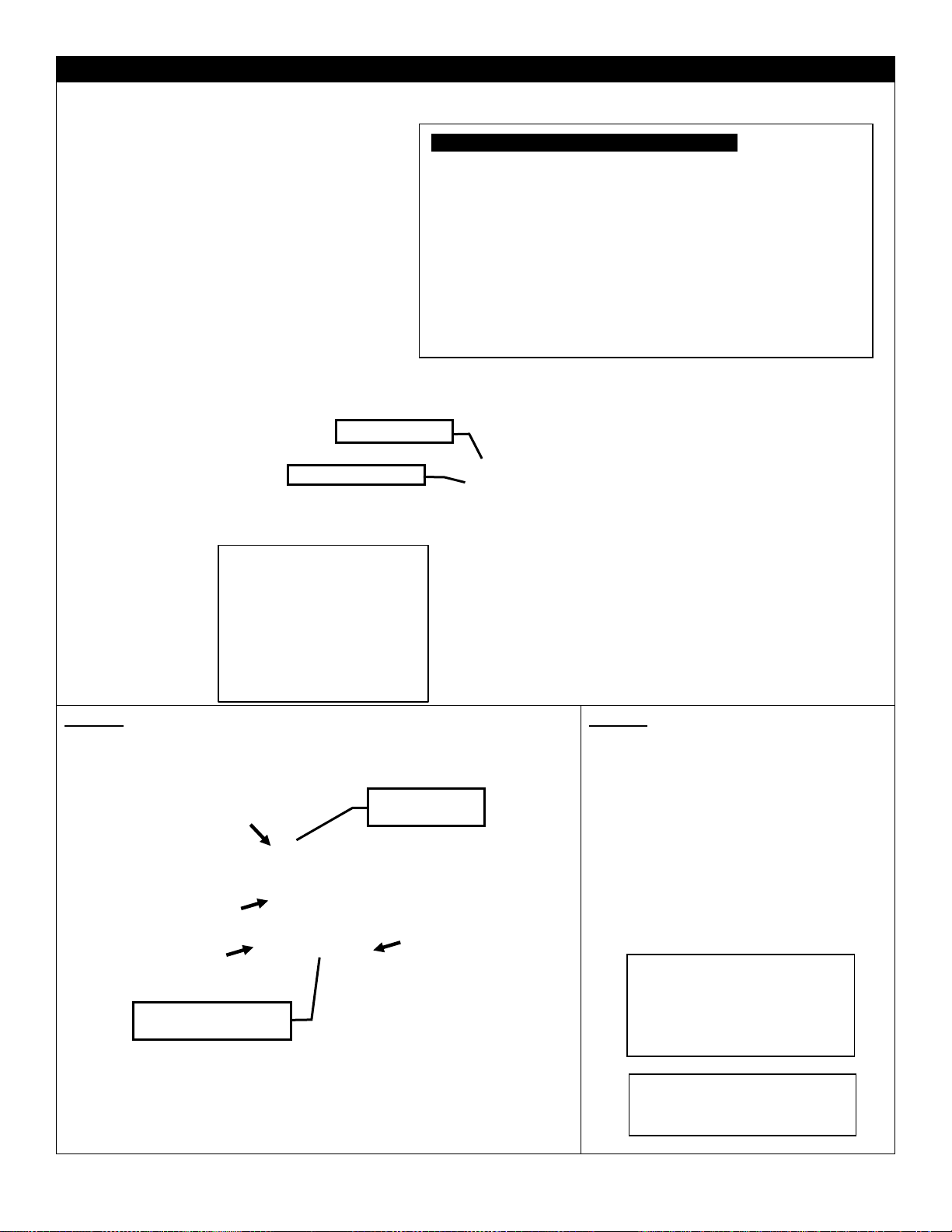
Page 41

Safety Information and Manual Lighting Instructions
FOR YOUR SAFETY READ BEFORE LIGHTING
Manual Lighting Instructions
Push Button Ignition (if equipped)
To Turn Off Gas Appliance
41
⚠WARNING: If you do not follow these instructions exactly, a fire or explosion may result causing property damage,
personal injury or loss of life.
A. This appliance must be lit by hand. When lighting,
follow these instructions exactly.
B. Before LIGHTING, smell all around the appliance
area for gas. Be sure to smell next to the floor,
because some gas is heavier than air and will settle
on the floor.
WHAT TO DO IF YOU SMELL GAS
• Do not try to light any appliance.
• Do not touch any electric switch; do not use any phone in your building.
• Immediately call your gas supplier from a neighbor’s phone. Follow the gas supplier’s instructions.
• If you cannot reach your gas supplier, call the fire department.
C. Use only your hand to turn the gas control knob or
valve. Never use tools. If the valve will not turn by
hand, don’t try to repair it, call a qualified service
technician. Force or attempted repair may result in a
fire or explosion.
D. Do not use this appliance if any part has been
underwater. Immediately call a qualified
technician to inspect the appliance, and to replace
part which has been underwater.
service
any
1. STOP! Read the safety information above.
2. Remove the top cover.
3. Find the manual gas control valve.
4. Place a burning match on top of burner in the
middle where ports are present. DO NOT HOLD
THE MATCH IN HAND. For Natural Gas unit
turn on the on/off valve slowly at the unit. For LP
unit turn the valve on the LP tank
counterclockwise all the way and then turn on
the on/off valve slowly at the unit.
1. STOP! Read the safety information above.
2. Remove the top cover.
3. Find the manual gas control valve and push
button igniter.
4. Push and hold the button on the igniter and
ensure sparking is occurring at the probes inside
the burner tray.
5. Turn ON gas supply and manual key valve.
5. If the burner does not light before the match
goes out, immediately turn the gas to off.
6. Wait at least five (5) minutes to clear out any
gas. If you have unsuccessfully tried to light the
burner, wait longer. Then smell for gas, including
near the floor. If you smell gas, STOP! Follow
“B” in the safety information above. If you don’t
smell gas, repeat step 4.
6. Gas should ignite within 10 seconds or less. If
the burner does not light turn the gas to off.
7. Wait at least five (5) minutes to clear out any
gas. Then smell for gas, including near the floor.
If you smell gas, STOP!
8. If you don’t smell gas, repeat step 4.
1. Turn the on/off valve to the off position at the
unit for natural gas unit. For LP unit, turn the
on/off valve to the off position at the unit and
then turn the valve on the LP tank to the off
position clockwise.
2.
Replace the top cover.
Page 42

Millivolt System, Lighting, and Burner Control
FOR YOUR SAFETY READ BEFORE LIGHTING
BEFORE LIGHTING
A This appliance has a pilot which must be lighted by hand. When
lighting the pilot, follow these instructions exactly.
B Smell all around the appliance area for gas. Be sure to smell next
to the floor because some gas is heavier than air and will settle on
the floor.
WHAT TO DO IF YOU SMELL GAS
Do not try to light an appliance.
Do not touch any electrical switch; do not use any phone in your
building.
Immediately call your gas supplier from a neighbour’s phone. Follow the
gas supplier’s instructions.
If you cannot reach your gas supplier, call the fire department.
C Use only your hand to push or turn the gas control knob. Never use
tools. If the knob will not push in or turn by hand, don’t try to repair it.
Call a qualified technician. Force or attempted repair may result in a fire
or explosion.
D Do not use the appliance if any part has been under water. Immediately
call a qualified service technician to inspect the appliance and to
replace any part of the control system which has been under water.
LIGHTING INSTRUCTIONS
1. Stop! Read the safety information above this label.
2. Set the thermostat to lowest setting.
3. Turn off all electrical power to the appliance.
4. Locate valve under the burner assembly.
5. If the control knob is not already in the off position, i.e. the word
“OFF” in the 9 o’clock position, then push in the gas control knob
slightly and turn clockwise to “OFF”. NOTE: Knob cannot be
turned from “PILOT” to “OFF” unless knob is pushed in slightly. Do
not use force.
6. Wait five [5] minutes to clear out any gas. If you then smell gas.
STOP! Follow “B” in the safety information above on this label. If
you don’t smell gas then go to the next step.
7. Now push in the control knob slightly and turn counter-clockwise
to the “PILOT” position.
8. Push in the control knob all the way and hold it. With the other
hand push in the red igniter button until you hear a click. Now
observe closely the pilot burner located on the rear center-left
hand side of the main burner.
If a flame has appeared then continue to depress the control knob for 20
seconds. If the flame did not appear then continue to depress the red
igniter button every 5 seconds until a flame is established. NOTE: If
after 30 seconds a flame has not yet been established then turn the
control knob back to the off position and repeat steps 5, 6 & 7.
9. Once the pilot has been established hold the control knob in the
depressed position for approximately 25 seconds before releasing. If
the flame goes out then repeat steps 7 and 8.
If the knob does not pop up when released, stop and immediately call
your service technician or gas supplier.
If the pilot will not stay lit after several tries, turn the gas control to
“OFF” and call your service technician.
10. Now turn the control knob to the “ON” position. The burner will not light
unless the wall switch thermostat or remote control is turned “ON” or in
the case of the thermostat there is a call for heat.
11. Close the access door and turn all electrical power back to the
appliance.
12. The pilot must be turned off when the unit is not in use.
TO TURN OFF THE APPLIANCE
1. Set the thermostat to lowest setting.
2. Turn off all electric power to the appliance if service is to be
performed.
3. Open the control access door.
4. Push in the gas control knob slightly and turn clockwise to the “OFF”
position. Do not force.
5. Replace control access panel.
Recommended Maximum Lead Length (Double Wire)
When Using Wall Switch or Thermostat
Wire Size
Max. Length
14ga
100ft [30.4m]
16ga
64ft [19.5m]
18ga
40ft [12.1m]
20ga
25ft [7.6m]
22ga
15ft [4.5m]
CAUTION: DO NOT WIRE 120V POWER TO
MILLIVOLT SWITCHES OR THERMOSTAT.
NOTE: Only one on/off device (manual on/off, remote control, or hard wired thermostat) should be connected to the
appliance at any one time, this is most important when installing an insert or stove as the on/off rocker switch is installed at
the factory.
WARNING: If you do not follow these instructions exactly, a fire or explosion may result causing property
damage, personal injury or loss of life.
To Wall Switch,
Thermostat*, Or
Remote Receiver
*In the U.S.A. Thermostats are not permitted for Vented Gas Fireplaces (ANSI Z21.50b-2009 -Decorative).
42
Page 43

MAP / MAN -MANUAL VALVE (DANTE)
MVN / MVP -MILLIVOLT VALVE
Models →
OB24MAN
OB24MAP
OB36MAN
OB36MAP
OB48MAN
OB48MAP
OB24MVN
OB24MVP
OB36MVN
OB36MVP
OB48MVN
OB48MVP
OB72MVN
OB72MVP
OB96MVN
OB96MVP
Fuel
Natural Gas
Propane
Natural Gas
Propane
Natural Gas
Propane
Natural Gas
Propane
Natural Gas
Propane
Natural Gas
Propane
Natural Gas
Propane
Natural Gas
Propane
Gas Control
Dante Adjustable
Millivolt Adjustable
Max / Min
(Btu)
40,000
40,000
60,000
60,000
63,500
60,000
27,500Lo
40,000Hi
31,500Lo
40,000Hi
39,000Lo
60,000Hi
48,000Lo
60,000Hi
54,000Lo
80,000Hi
61,000Lo
80,000Hi
83,000Lo
120,000Hi
91,000Lo
115,000Hi
110,000Lo
156,000Hi
125,000Lo
157,000Hi
Orifice Size
(0-4500ft)
#40
#50
#31
#43
#30
#43
#31
#49
#25
#43
#14
#37
#19 [2ea]
#43 [2ea]
#10 [2ea]
#37 [2ea]
Air Shutter
1/16” Open
Fully Open
1/16” Open
Fully Open
1/16” Open
Fully Open
1/16” Open
Fully Open
1/16” Open
Fully Open
1/16” Open
Fully Open
1/16” Open
Fully Open
1/16” Open
Fully Open
Gas Inlet Size
Dante, 3/8” NPT
S.I.T. 820 Nova, 3/8” NPT
S.I.T. 820 Nova, 1/2” NPT
Gas Supply
Pressure
Minimum
Normal
Maximum
Minimum
Normal
Maximum
Natural Gas
7” (Unregulated)
7” (Unregulated)
7” (Unregulated)
5.5”
7”
10”
Liquid
Propane
11” Hose Regulator
11” Hose Regulator
11” Hose Regulator
11”
11”
13”
Manifold
Pressure High
N/A
N/A
3.5” w.c. [0.87KPa] NG
10” w.c. [2.61KPa] LP
Manifold
Pressure Low
N/A
N/A
1.6” w.c. [0.40KPa]
6.3” w.c. [1.57KPa]
IMPORTANT: Always check for gas leaks with a soap and water solution. DO NOT USE OPEN FLAME FOR LEAK TESTING.
For the state of Massachusetts a T-handle gas shut-off valve must be used on a gas appliance. This T-handle gas shut-off valve must be listed and approved by the state of Massachusetts.
This is in reference to the state of Massachusetts state code CMR238.
43
1. The gas pipeline can be brought in through either the left side or the bottom of the appliance. A knockout is provided at either location to allow for the gas pipe installation and testing of any gas
2. The gas control inlet is 3/8” NPT. Typical installation layout for rigid pipe is shown at right.
3. When using copper or flex connector, use only approved fittings. Always provide a union so that gas line can be easily
4. When a vertical section of gas pipe is required for the installation, a condensation trap is needed. See CAN/CGA-B149.1 or .2
5. For natural gas, a minimum of 3/8” iron pipe with gas minimum pressure of 4.5” w.c. must be used for supply from the gas
6. Ports are accessible for test gauge connection both on the inlet and outlet of the gas valve.
7. Turn the gas supply ON and check for leaks. DO NOT USE OPEN FLAME FOR THIS PURPOSE. Use an approved leak
8. The appliance and its individual shutoff valve must be disconnected from the gas supply piping system during any pressure
9. The appliance must be isolated from the gas supply piping system by closing its individual shutoff valve during any pressure
Note: The gas line connection may be made of 1/2” rigid pipe, 1/2” copper pipe or an approved flex connector. Since some
municipalities have additional local codes, it is always best to consult your local authorities and the current CAN/CGA - B149.1 or .2
installation code in Canada or the National Fuel Gas code ANSI Z223.1 in the U.S.A.
disconnected for burner or fan servicing. See gas specification for pressure details and ratings.
for code details.
meter. Consult with the local gas utility if any questions arise concerning pipe sizes.
testing solution.
testing of that system at test pressures in excess of 1/2psig [3.5 KPa].
testing of the gas supply piping system at test pressures equal to or less than 1/2psig [3.5 KPa].
This gas appliance should be installed by a qualified installer in accordance with local building codes and with current CAN/CGA - B149.1 or .2 installation codes for Gas Burning appliances and
equipment in Canada and the National Fuel Gas Code ANSI Z223 in the U.S.A.
connection.
Gas Line Installation and Specifications
Page 44

LP Cylinder Requirements
NOTE: Cylinders acceptable for use inside this appliance must be compatible with the retention means shown here.
The LP gas supply cylinder used with LP models must be constructed
and marked in accordance with the specifications for LP-gas cylinders
of the U.S. Department of Transportation (DOT) Specifications for LP-
Gas Cylinders, or the Standard for Cylinders, Spheres and Tubes for
Transportation of Dangerous Goods and Commission, CAN/CSA-
B339, as applicable.
The LP gas supply cylinder used with LP models must be provided
with a listed overfilling prevention device.
The pressure regulator and hose assembly supplied with LP models
(PN# 27FP-900FF or 24OFS-P120) must be used. Replacement
pressure regulators and hose assemblies must be those specified in
this manual.
Always check for gas leaks with a soap and water solution. DO NOT
USE OPEN FLAME FOR LEAK TESTING.
When an LP model is not in use, the LP-gas must be turned off at the
supply cylinder.
At altitudes above 4500ft appliances should be derated 4% every
1000ft. However, check with local gas supplier as fuel supply may
already be adjusted.
Refer to Burner System Maintenance for proper pilot orientation.
Refer to Burner System Maintenance for pilot and main burner
flame appearance.
Refer to Gas Line Installation and Specifications for leak testing
procedures.
Refer to Gas Line Installation and Specifications for manifold
pressures.
Refer to Gas Line Installation and Specifications for gas inlet
pressures.
Refer to Gas Line Installation and Specifications for input rates.
Refer to Lighting Instructions for normal sequence of the ignition
system.
TANK RETAINER - Included
with all MAP Burners and LP
Conversion Kits
1. Connect foot ring of LP Tank to Tank
Retainer with thumbscrew.
2. Fasten Tank retainer to mounting surface
with lag screw.
3. Concrete anchor required for concrete
surface (not supplied).
LP Conversion Kits for Millivolt and Manual Systems
Kit Number
Description
Pilot Orifice
Burner Orifice
Brass (1000-255)
Brass Nipple
Air Shutter
Hi/Lo Regulator
(if applicable)
24OB-CKLP
LP Conversion For
OB24
-Millivolt-
1001-P167SI
#30 (977.167)
#49
1000-253
Closed
Fully Open
1001-P202si
(0.907.202)
36OB-CKLP
LP Conversion
For OB36
-Millivolt-
1001-P167SI
#30 (977.167)
#43
1000-253
Closed
Fully Open
1001-P202si
(0.907.202)
48OB-CKLP
LP Conversion
For OB48
-Millivolt-
1001-P167SI
#30 (977.167)
#37
1000-253
Closed
Fully Open
1001-P202si
(0.907.202)
72OB-CKLP
LP Conversion
For OB72
-Millivolt-
1001-P167SI
#30 (977.167)
#43 [Qty 2]
1000-253
Closed
Fully Open
1001-P202si
(0.907.202)
96OB-CKLP
LP Conversion
For OB96
-Millivolt-
1001-P167SI
#30 (977.167)
#37 [Qty 2]
1000-253
Closed
Fully Open
1001-P202si
(0.907.202)
24OB-CKLP5
c/w 5’ hose
LP Conversion For
OB24
-Dante Manual-
N/A
#50
1000-253
Closed
Fully Open
27FP-900FF
(5ft Hose & Regulator)
24OB-CKLP10
c/w 10’ hose
LP Conversion For
OB24
-Dante Manual-
N/A
#50
1000-253
Closed
Fully Open
24OFS-P210
(10ft Hose & Regulator)
36-48OB-CKLP5
c/w 5’ hose
LP Conversion For
OB36
-Dante Manual-
N/A
#43
1000-253
Closed
Fully Open
27FP-900FF
(5ft Hose & Regulator)
36-48OB-CKLP10
c/w 10’ hose
LP Conversion For
OB36
-Dante Manual-
N/A
#43
1000-253
Closed
Fully Open
24OFS-P210
(10ft Hose & Regulator)
All LP Conversion Kits include a Tank retainer. This Bracket is NOT USED on Outdoor Fire Tables.
Tank retainer
44
Page 45

Gas Conversion – PART A - MANUAL SYSTEMS –
NOTE: CONVERSION SHOULD BE COMPLETED BEFORE BURNER IS INSTALLED.
TO CONVERT MAP SYSTEMS TO MAN:
1. Remove [2] screws from Orifice Retainer Bracket.
2. Remove Burner Orifice from Air Shutter. Using a 1/2” wrench,
disconnect Burner Orifice from brass fitting and replace with
supplied NG Burner Orifice.
3. Set Air Shutter Adjustment to 1/16”.
4. Re-insert new Burner Orifice into Air Shutter.
5. Re-attach Orifice Retainer Bracket to Burner Tray.
6. Disconnect LP Hose and Regulator from Valve Assembly.
TO CONVERT MAN SYSTEMS TO MAP:
1. Remove [2] screws from Orifice Retainer Bracket.
2. Remove Burner Orifice from Air Shutter. Using a 1/2” wrench,
disconnect Burner Orifice from brass fitting and replace with
supplied LP Burner Orifice.
3. Set Air Shutter Adjustment Fully Open.
4. Re-insert new Burner Orifice into Air Shutter.
5. Re-attach Orifice Retainer Bracket to Burner Tray.
6. Connect LP Hose and Regulator to Valve Assembly.
WARNING
This conversion kit shall be installed by a qualified service agency in accordance with the
manufacturer’s instructions and all applicable codes and requirements of the Authority
Having jurisdiction. If the information on in these instructions is not followed exactly, a fire,
explosion or production of carbon monoxide may result causing property damage,
personal injury or loss of life.
The qualified service agency is responsible for the proper installation of this kit. The
installation is not proper and complete until the operation of the converted appliance is
checked as specified in the manufacturer’s instructions supplied with the kit.
Air Shutter Adjustment:
1/16” for Natural Gas
Fully Open for Propane
Burner Orifice
See Chart for Size
Orifice Retainer Bracket
Burner Tray
TANK RETAINER
Included with all MAP Burners and LP
Conversion Kits
NOT USED ON FIRE TABLES.
10ft LP Hose & Regulator
Included in 24OB-CKLP10
5ft LP Hose & Regulator
Included in MAP Systems &
24OB-CKLP5
PN: 27FP-900FF
PN: 24OFS-P120
45
Caution- the gas supply shall be shut off prior to disconnecting the electrical power, before proceeding with the
conversion.
Page 46

Gas Conversion –PART A - MILLIVOLT SYSTEMS -
NOTE: CONVERSION SHOULD BE COMPLETED BEFORE BURNER IS INSTALLED.
TO CONVERT MILLIVOLT GAS SYSTEMS:
1. Remove [2] screws from Orifice Retainer Bracket.
2. Remove Burner Orifice from Air Shutter. Using a
1/2” wrench, disconnect Burner Orifice from brass
fitting and replace with appropriate Burner Orifice.
3. Set Air Shutter Adjustment to Fully Open for LP,
and 1/16” for NG.
4. Re-insert new Burner Orifice into Air Shutter.
5. Re-attach Orifice Retainer Bracket to Burner Tray.
6. Remove Filler Strips and Pilot Shield to access Pilot
Assembly.
7. Install new Pilot Orifice and Hi/Lo Valve Regulator by
following instructions supplied with Conversion Kit (also see
Parts B & C of Conversion Kit Instructions).
WARNING
This conversion kit shall be installed by a qualified service agency in accordance with the
manufacturer’s instructions and all applicable codes and requirements of the Authority
Having jurisdiction. If the information on in these instructions is not followed exactly, a
fire, explosion or production of carbon monoxide may result causing property damage,
personal injury or loss of life.
The qualified service agency is responsible for the proper installation of this kit. The
installation is not proper and complete until the operation of the converted appliance is
checked as specified in the manufacturer’s instructions supplied with the kit.
Pilot Shield
Pilot Assembly
Filler Strip
Burner Orifice
See Chart for Size
Orifice Retainer Bracket
Burner Tray
Filler Strip
TANK RETAINER
Included with all MAP Burners
and LP Conversion Kits
NOT USED ON FIRE TABLES.
Air Shutter Adjustment:
1/16” for Natural Gas
Fully Open for Propane
46
Caution- the gas supply shall be shut off prior to disconnecting the electrical power, before proceeding with the
conversion.
Page 47

Gas Conversion for Top Convertible Pilot (Series 019065X) – PART B
Instructions for converting SIT 190 series pilot burner injection from NG to LPG and from LPG to NG only. This
information should be considered as supplemental to the Appliance Manufacturer’s Instructions.
WARNING: The installation of this conversion kit must only be undertaken by a qualified and certified gas
appliance installer.
1. Shut off the gas supply to the appliance.
2. Allow the pilot burner to cool to room temperature.
WARNING: Touching a hot pilot burner can
result in injury.
3. The pilot hood is held in place by spring pressure.
Remove the hood by pulling it directly up from the
pilot bracket (a).
4. Insert a 5/32” or 4mm Allen wrench into the
hexagonal key-way of the injector (b), and rotate it
counter-clockwise until it is free of the injector
journal (c).
5. Verify that the new injector is proper for the
application. The injector size is stamped on the
side of the injector near the top. LPG injectors have
a groove machined around their circumference
near the top, while NG injectors do not have a
groove (e). Refer to the Appliance Manufacturers
instruction sheet for the proper injector size.
6. Insert the Allen wrench into the end of the injector.
Then, insert into injector journal, and rotate the
injector clockwise until a torque of 9 in-lbs is
achieved.
7. Replace the pilot hood by aligning the tab on the
base of the hood with the slot in the side of the pilot
journal, and push the hood down, directly onto the
pilot bracket (d). The hood must sit squarely on the
bracket for proper operation. Check to insure that
the hood is properly seated onto the pilot bracket.
(a) (b)
(c) (d)
(e)
WARNING: This conversion kit must only be applied as part of a conversion kit supplied by the appliance
Manufacturer for the specific appliance, and type of gas being converted.
INSTALLER NOTICE: These instructions must be left with appliance.
47
Page 48

Gas Conversion for Modulator – PART C
48
Page 49

Optional Electronic Spark Assist MVN / MVP Valve Systems
Battery Igniter
OLTN / OLTW – Top View
OFP – Top View
OLTN / OLTW
Ignition Switch
Ignition Switch
Battery Igniter
Ignition Switch
Battery Igniter
Ignition Switch
Battery Igniter
OFP
49
(Part Number OFP42SA)
A Battery powered module is available to assist in lighting the pilot burner. See below for installation.
Page 50

Outdoor Burners - Troubleshooting the Gas Control System
NOTE: Before troubleshooting the gas control system, be sure external gas shut off is in the “ON” position.
Problem
Possible Causes
Corrective Action
Spark igniter will not
light
Defective or misaligned electrode
at pilot.
Check for spark at electrode and pilot: if no spark and
electrode wire is properly connected, replace igniter.
Defective igniter
(push-button)
Using a match, light pilot, If pilot lights, turn off pilot and
push the red button again. If pilot will not light, check gap
at electrode and pilot- gap should be 1/8” to 1/4” to have
a strong spark.
Pilot will not light
Safety Switch is Depressed.
Clear any obstructions and make sure Lever Arm is not
bent or damaged.
Pilot will not stay lit
after carefully
following lighting
instructions.
Defective Valve Magnet
Turn valve knob “ON”, place wall switch “ON”. Millivolt
meter should read greater than 100mv. If the reading is
okay and the burner does not come on, replace the gas
valve.
Pilot burning, no gas
to burner, Valve
knob “ON”, Wall
Switch “ON”
Wall Switch or wires defective
Check wall switch and wires for proper connections.
Jumper wire across terminals at wall switch. If burner
comes on, replace defective wall switch. If okay, jumper
wire across wall switch wires at valve. If burner comes
on, wires are faulty or connections are bad.
Generator may not be generating
sufficient voltage
Check generator with millivolt meter. Take reading at
generator terminals of gas valve. Should read 325
millivolts minimum while holding valve knob depressed in
pilot position and wall switch “OFF”. Replace faulty
generator if reading is below specified minimum.
Plugged burner orifice
Check burner orifice for stoppage and remove.
Defective automatic valve
operator
Remove all switch wires from gas valve. Install jumper
wires from TPTH and TH terminals of gas valve. Turn
valve “ON”. If main burner does not light, replace valve.
Frequent Pilot
outage problem
Pilot flame may be too low or
blowing (high) causing the pilot
safety to drop out
Clean and/or adjust pilot flame for maximum flame
impingement on generator.
Windy Conditions
-Move appliance to a less windy area if possible
-Use when conditions are less windy
-Install a wind guard
Burners burn with
yellow flame,
accompanied by the
smell of gas.
Possible spider web or other
debris.
Thoroughly clean burner venturi.
50
Page 51

Burners
Outdoor Burners –Plumbing Parts
OB24MAP / OB36MAP / OB48MAP
Part
Description
1.
3632HB-P496C
Brass Elbow, 3/8” Tube to 3/8”NPT
2.
3632HB-P496C-M
Brass Elbow, 3/8” Tube to 3/8”NPT, tapped,
with Manometer Plug (30FPB-P118A) inserted
3.
30FPB-P118A
Brass Manometer Plug, 1/8” NPT
4.
24L-P110DC
Brass Bushing, 1/2” NPT x 3/8”FPT
5.
27FP-CPBVS
90° Ball Valve c/w Key Way Assembly (Dante)
6.
20FP-116
Key Way Installation Tool
7.
27FP-900FF
LP Reg & 5ft Hose (I4T60GRQC)
8.
42MCV-P16FF
3/8” Stainless Steel Flex Connector -16” Long
9.
1000-225
Brass Orifice, NG or LP (Specify size)
10.
27FP-P904FF
3/8” Tube OD x 1/8”MPT
11.
24OB-102
Orifice Retainer Bracket
12.
24OB-105
Ball Valve Bracket
13.
30FPB-KEY
Ball Valve Key
14.
24OB-P152
Push Button Igniter (Battery not included)
15.
24OB-107A
Electrode Wire Assembly (c/w Mount Plate)
16.
24OB-121A
Tank Retainer
Part
Description
1.
1001-P714SI
Pilot Assembly (c/w Mount Plate)
2.
42MCV-P16FF
3/8” Stainless Steel Flex Connector -16” Long
3.
24OB-102
Orifice Retainer Bracket
4.
27FP-P904FF
3/8” Tube OD x 1/8”MPT
5.
1000-225
Brass Orifice, NG or LP (Specify size). Refer to
Chart in Manual
6.
26IDV-P324A
Pilot Tube with Fittings
7.
3632HB-P496C (x2)
Brass Elbow, 3/8” Tube to 3/8”NPT
8.
24OB-109
Valve Bracket
9.
1001-P640si
Millivolt Valve NG –Hi/Lo
10.
1000-214
Piezo Igniter
11.
36HB-115
Piezo Bracket
OB24MVN / OB36MVN / OB48MVN
Part
Description
1.
1000-225
Brass Orifice, NG or LP (Specify size).
Refer to Chart in Manual
2.
27FP-P904FF
3/8” Tube OD x 1/8”MPT
3.
24OB-102
Orifice Retainer Bracket
4.
42MCV-P16FF
3/8” Stainless Steel Flex Connector -16”
Long
5.
24L-P456C
Brass Tee, 3/8” Tube OD x 3/8” MPT
6.
24L-P1212
1/2” Yellow Flex (c/w Connectors) – 12”
Long
7.
1001-P714SI
Pilot Assembly (c/w Mount Plate)
8.
26IDV-P324
Pilot Tube with Fittings
9.
24OB-109
Valve Bracket
10.
1001-P658si
Millivolt Valve, 1/2” Hi Output
11.
1000-214
Piezo Igniter
OB72MVN / OB96MVN
1 2 3 4 5 6 7
8
9
10
119 12134 1 2
3
4
5
6 7 8 9 10
11
12
11
10
9
8 7 6
5
4
3 2 1 1 2
3
4
7
141516
51
Page 52

Barbara Jean Series- Parts List
Listed for Canada and USA
NUMBER
DESCRIPTION
BURNERS c/w Valve
OB24MAP
Linear Burner 24" ‐ Manual Valve Propane* ‐
40,000 BTU
OB24MAN
Linear Burner 24" ‐ Manual Valve Natural Gas ‐
40,000 BTU
OB24MVN
Linear Burner 24" ‐ Millivolt Valve Natural Gas** ‐
40,000 BTU
OB36MAP
Linear Burner 36" ‐ Manual Valve Propane* ‐
60,000 BTU
OB36MAN
Linear Burner 36" ‐ Manual Valve Natural Gas ‐
60,000 BTU
OB36MVN
Linear Burner 36" ‐ Millivolt Valve Natural Gas** ‐
60,000 BTU
OB48MAP
Linear Burner 48" ‐ Manual Valve Propane* ‐
60,000 BTU
OB48MAN
Linear Burner 48" ‐ Manual Valve Natural Gas ‐
63,500 BTU
OB48MVN
Linear Burner 48" ‐ Millivolt Valve Natural Gas** ‐
80,000 BTU
OB72MVN
Linear Burner 72" ‐ Millivolt Valve Natural Gas** ‐
120,000 BTU
OB96MVN
Linear Burner 96" ‐ Millivolt Valve Natural Gas** ‐
156,000 BTU
*LP Manual (MAP) valve systems are shipped with an
accompanying orifice for NG conversion.
**Millivolt valve systems are shipped as NG systems (MVN) and
require a Conversion Kit for LP conversion.
CONVERSION KITS
24OB-CKLP
LP Conversion Kit for OB24-MVN
c/w #49 Burner Orifice, Pilot Orifice, Regulator
36OB-CKLP
LP Conversion Kit for OB36-MVN
c/w #43 Burner Orifice, Pilot Orifice, Regulator
48OB-CKLP
LP Conversion Kit for OB48-MVN
c/w #37 Burner Orifice, Pilot Orifice, Regulator
72OB-CKLP
LP Conversion Kit for OB72-MVN
c/w (Qty 2) #43 Burner Orifices, Pilot Orifice,
Regulator
96OB-CKLP
LP Conversion Kit for OB96-MVN
c/w (Qty 2) #37 Burner Orifices, Pilot Orifice,
Regulator
24OB-CKLP5
LP Conversion Kit for OB24-MAN
c/w #50 Orifice, Tank Retainer Bracket, 5’ Hose &
Regulator
24OB-CKLP10
LP Conversion Kit for OB24-MAN
c/w #50 Orifice, Tank Retainer Bracket, 10’ Hose
& Regulator
36-48OB-CKLP5
LP Conversion Kit for OB36-MAN, OB48MAN
c/w #43 Orifice, Tank Retainer Bracket, 5’
Hose & Regulator
36-48OB-CKLP10
LP Conversion Kit for OB36-MAN, OB48MAN
c/w #43 Orifice, Tank Retainer Bracket, 10’
Hose & Regulator
GLASS MEDIA
5 lbs. per Foot of Burner (i.e.: 24" burner = 10lbs)
MQG5ZG
Glass Media ‐ ZIRCON Glacier Ice ‐ 5 lbs
MQG5A
Glass Media ‐ 1/2" Cobalt Blue ‐ 5 lbs
MQG5B
Glass Media ‐ 1/2" Black ‐ 5 lbs
MQG5C
Glass Media ‐ 1/2" Bronze ‐ 5 lbs
MQG5W
Glass Media ‐ 1/2" White ‐ 5lbs
ROCKS AND LOGS
MQRBD3
Drift Wood ‐ Log Set ‐ 5 pcs.
MQRBD4
Drift Wood ‐ Log Set 3 pcs.
MQROCK2
Rock Set ‐ Contemporary Collection ‐ Natural
MQROCK3
Rock Set ‐ Contemporary Collection ‐ Multi‐
Colored
MQSTONE
Decorative Stones ‐ 80 pc. Set
MQSTONE10
Decorative Stones ‐ 10 pc. Set
RBCB1
Cannonballs ‐ Assorted size and colors x 14
OPTIONAL ACCESSORIES
OFP42SA
Spark Assist ‐ (AA Battery not included)
GFRC
Remote Control Millivolt ‐ On/Off
OBUVM
Universal Valve Bracket Mount (for Custom
Applications)
BURNER REPLACEMENT PARTS
24OB-100A
Replacement Burner – No Valve
36OB-100A
Replacement Burner– No Valve
48OB-100A
Replacement Burner– No Valve
24OB-FSK
Filler Strip Kit (3 Pcs.)
36OB-FSK
Filler Strip Kit (3 Pcs.)
48OB-FSK
Filler Strip Kit (3 Pcs.)
72OB-FSK
Filler Strip Kit (6 Pcs.)
96OB-FSK
Filler Strip Kit (6 Pcs.)
24OB-258
Pilot Shield
OUTDOOR FIRE STANDS
OFS24MAP
Fire Stand with Linear Burner 24" ‐ Manual Valve
Propane ‐ 40,000 BTU
OFS24MAN
Fire Stand with Linear Burner 24" ‐ Manual Valve
Natural Gas ‐ 40,000 BTU
OFS36MAP
Fire Stand with Linear Burner 36" ‐ Manual Valve
Propane ‐ 60,000 BTU
OFS36MAN
Fire Stand with Linear Burner 36" ‐ Manual Valve
Natural Gas ‐ 60,000 BTU
OFS48MAP
Fire Stand with Linear Burner 48" ‐ Manual Valve
Propane ‐ 60,000 BTU
OFS48MAN
Fire Stand with Linear Burner 48" ‐ Manual Valve
Natural Gas ‐ 60,000 BTU
OFS24MAP-BL
Fire Stand with Linear Burner 24" ‐ (as above)
Powder Coat Black Top
OFS24MAN-BL
Fire Stand with Linear Burner 24" ‐ (as above)
Powder Coat Black Top
OFS36MAP-BL
Fire Stand with Linear Burner 36" ‐ (as above)
Powder Coat Black Top
OFS36MAN-BL
Fire Stand with Linear Burner 36" ‐ (as above)
Powder Coat Black Top
OFS48MAP-BL
Fire Stand with Linear Burner 48" ‐ (as above)
Powder Coat Black Top
OFS48MAN-BL
Fire Stand with Linear Burner 48" ‐ (as above)
Powder Coat Black Top
52
Page 53

OUTDOOR FIRE TABLES
TABLE BODIES
OLT24BG
Outdoor Fire Table ‐ Body (use 24" Burner) ‐
Black with Gray End Doors
OLT24BB
Outdoor Fire Table ‐ Body (use 24" Burner) ‐
Black with Brown End Doors
OLT36BG
Outdoor Fire Table ‐ Body (use 36" Burner) ‐
Black with Gray End Doors
OLT36BB
Outdoor Fire Table ‐ Body (use 36" Burner) ‐
Black with Brown End Doors
OLT48BG
Outdoor Fire Table ‐ Body (use 48" Burner) ‐
Black with Gray End Doors
OLT48BB
Outdoor Fire Table ‐ Body (use 48" Burner) ‐
Black with Brown End Doors
TABLE TOPS
OLT24TNG
Table Top ‐ Narrow ‐ Black with Grey Trim ‐ 39
1/8" L x 20 1/16" W
OLT24TNB
Table Top ‐ Narrow ‐ Black with Brown Trim ‐ 39
1/8" L x 20 1/16" W
OLT24TWG
Table Top ‐ Wide ‐ Black with Grey Trim ‐ 42
13/16" L x 28 5/16 W
OLT24TWB
Table Top ‐ Wide ‐ Black with Brown Trim ‐ 42
13/16" L x 28 5/16 W
OLT36TNG
Table Top ‐ Narrow ‐ Black with Gray Trim ‐ 51
1/8" L x 20 1/16 W
LT36TNB
Table Top ‐ Narrow ‐ Black with Brown Trim ‐ 51
1/8" L x 20 1/16 W
OLT36TWG
Table Top ‐ Wide ‐ Black with Gray Trim ‐ 54
13/16" L x 28 5/16 W
OLT36TWB
Table Top ‐ Wide ‐ Black with Brown Trim ‐ 54
13/16" L x 28 5/16 W
OLT48TNG
Table Top ‐ Narrow ‐ Black with Gray Trim ‐ 63
1/8" L x 20 1/16 W
OLT48TNB
Table Top ‐ Narrow ‐ Black with Brown Trim ‐ 63
1/8" L x 20 1/16 W
OLT48TWG
Table Top ‐ Wide ‐ Black with Gray Trim ‐ 66
13/16" L x 28 5/16 W
OLT48TWB
Table Top ‐ Wide ‐ Black with Brown Trim ‐ 66
13/16" L x 28 5/16 W
OPTIONAL WIND GUARDS -4 SIDED-
OB24WG
Wind Guard for 24” Burners- c/w Tempered Glass
[4pcs], Corner Brackets [8pcs], and Rubber Feet
[4pcs]
OB36WG
Wind Guard for 36” Burners- c/w Tempered Glass
[4pcs], Corner Brackets [8pcs], and Rubber Feet
[4pcs]
OB48WG
Wind Guard for 48” Burners- c/w Tempered Glass
[4pcs], Corner Brackets [8pcs], and Rubber Feet
[4pcs]
OB72WG
Wind Guard for 72” Burners- c/w Tempered Glass
[4pcs], Corner Brackets [8pcs], and Rubber Feet
[4pcs]
OB96WG
Wind Guard for 96” Burners- c/w Tempered Glass
[4pcs], Corner Brackets [8pcs], and Rubber Feet
[4pcs]
REPLACEMENT GLASS AND BRACKETS
24G-101
Glass Panel- 5-1/2”H x 9-5/8”W
24G-102
Glass Panel- 5-1/2”H x 28-3/16”W
36G-101
Glass Panel- 5-1/2”H x 40-3/16”W
48G-101
Glass Panel- 5-1/2”H x 52-3/16”W
72G-101
Glass Panel- 5-1/2”H x 76-3/16”W
96G-101
Glass Panel- 5-1/2”H x 100-3/16”W
24G-P202
Glass Corner Bracket- c/w neoprene glass mount
screws
24G-P205
Bottom Button- Rubber base for Glass Corner
Bracket (24G-P202)
72G-P202
Glass Mount Bracket- c/w neoprene glass mount
screws. For OFP series fireplaces.
OUTDOOR FIREPLACES
OFP4336S1
Outdoor Linear Fireplace ‐ 36" Burner ‐ Millivolt
Natural Gas ‐ Single Side
OFP4336S2
Outdoor Linear Fireplace ‐ 36" Burner ‐ Millivolt
Natural Gas ‐ See Through
OFP5548S1
Outdoor Linear Fireplace ‐ 48" Burner ‐ Millivolt
Natural Gas ‐ Single Side
OFP5548S2
Outdoor Linear Fireplace ‐ 48" Burner ‐ Millivolt
Natural Gas ‐ See Through
OFP7972S1
Outdoor Linear Fireplace ‐ 72" Burner ‐ Millivolt
Natural Gas ‐ Single Side
OFP7972S2
Outdoor Linear Fireplace ‐ 72" Burner ‐ Millivolt
Natural Gas ‐ See Through
OPTIONAL SURROUNDS
OFP43SS
Stainless Steel Surround for OFP54336S1 (1
required) or OFP4336S2 (2 required)
OFP55SS
Stainless Steel Surround for OFP5548S1 (1
required) or OFP5548S2 (2 required)
OFP79SS
Stainless Steel Surround for OFP7972S1 (1
required) or OFP7972S2 (2 required)
OPTIONAL WEATHER COVERS
OFP43WC
Stainless Steel Weather Cover for OFP54336S1
(1 required) or OFP4336S2 (2 required)
OFP55WC
Stainless Steel Weather Cover for OFP5548S1 (1
required) or OFP5548S2 (2 required)
OFP79WC
Stainless Steel Weather Cover for OFP7972S1 (1
required) or OFP7972S2 (2 required)
OPTIONAL LED LIGHTING
OLK24
24” Light Kit- c/w Control Box, Remote Control,
LED Light Strips [2pcs], Glass Panels [3pcs]
OLK36
36” Light Kit- c/w Control Box, Remote Control,
LED Light Strips [2pcs], Glass Panels [3pcs]
OLK48
48” Light Kit- c/w Control Box, Remote Control,
LED Light Strips [2pcs], Glass Panels [3pcs]
OLK72
72” Light Kit- c/w Control Box, Remote Control,
LED Light Strips [4pcs], Glass Panels [6pcs]
MISCELLANEOUS ITEMS
27FP-900FF
LP Regulator & 5ft Hose (I4T60GRQC)
24OFS-P120
LP Regulator & 10ft Hose (I6C120FS6GRQC)
53
Page 54

LIMITED WARRANTY
54
Save this certificate. It gives you specific legal rights, and you may also have other rights which may vary from one
province or state to another.
In the event your unit needs servicing contact your dealer or contractor who installed or services your unit. When
requesting service, please have the model and serial number from each unit readily available. If your dealer needs
assistance, the distributor is available for support and we, in turn support the distributor's efforts.
Fill in the installation date and model and serial numbers of the unit in the space provided below and retain this limited
warranty for your files.
GENERAL TERMS
This limited warranty applies only while the unit remains at the site of the original installation and only if the unit is installed
inside the continental United States, Alaska, Hawaii and Canada. The warranty applies only if the unit is installed and
operated in accordance with the printed instructions and in compliance with applicable installation, building codes and
good trade practices.
The burner is warranted against defects for five years. All other components such as gas valves, thermocouples, igniters,
lights and media are warranted against defects for one year.
This limited warranty further does not cover any scratches, dents, painted finishes, corrosion or discoloring by heat,
abrasive and chemical cleaners, nor chipping on porcelain powder coated parts.
During the first year after installation, we will provide a replacement for any component part of your unit found to be
defective in materials or workmanship. The part to be replaced must be returned to our distributor in exchange for the
replacement part.
In lieu of providing a replacement part, we may, at our option, provide the distributor's component purchase price from us
or a credit equal to the distributor’s component purchase price from us toward the purchase of any new unit which we
distribute. If a credit is given in lieu of a replacement part, the rating plate from the unit being replace must be submitted
on a warranty claim and the unit being replaced must be made available to our distributor for disposition.
In establishing the date of installation for any purpose including determination of the starting date for the term of this
limited warranty, reasonable proof of the original installation date must be presented*, otherwise the effective date will be
based upon the date of manufacture plus thirty (30) days.
Any labor, material, freight and/or handling charges associated with any repair or replacement pursuant to this limited
warranty will be your responsibility. In this warranty the word "installation" means original installation.
We will not be responsible for and you the user will pay for: (a) damages caused by accident, abuse, negligence, misuse,
riot, fire, flood, or Acts of God (b) damages caused by operating the unit where there is a corrosive atmosphere containing
chlorine, fluorine, or any other damaging chemicals (other than in a normal residential environment) (c) damages caused
by any unauthorized alteration or repair of the unit affecting its stability or performance (d) damages caused by improper
matching or application of the unit or the unit's components (e) damages caused by failing to provide proper maintenance
and service to the unit (f) any expenses incurred for erecting disconnecting or dismantling the unit (g) parts or supplies
used in connection with service or maintenance (h) damage repairs, inoperation or inefficiency resulting from faulty
installation or application (i) electricity or fuel costs or any increase in electricity or fuel cost whatsoever including
additional or unusual use of supplemental electric heat.
We shall not be liable for any incidental, consequential, or special damages or expenses in connection with any use or
failure of this unit. We have not made and do not make any representation or warranty of fitness for a particular use or
purpose and there is no implied condition of fitness for a particular use or purpose. We make no express warranties
except as stated in this limited warranty. No one is authorized to change this limited warranty or to create for us any other
obligation or liability in connections with this unit. Any implied warranties shall last for one year after the original
installation. Some states and provinces do not allow the exclusion or limitation of incidental or consequential damages or
do not allow limitations on how long an implied Warranty or condition lasts so the above limitations or exclusions may not
apply to you. The provisions of this limited warranty are in additions to and not a modification of or subtraction from any
statutory warranties and other rights and remedies provided by law.
Model No.:_____________________________________________ Serial No.:_________________________________
Date Installed: ___________________________________________
*You must retain the original records that can establish the installation date of your unit.
 Loading...